

Page 1
Reissued on April 30, 1991
Technical Bulletin No. RTB-003
SUBJECT: Corona Casing Cleaning DATE:April 30,1991
PAGE: 1 of 1
PREPARED BY: M. Kitajima
CHECKED BY:
CLASSIFICATION:
Action Required
Troubleshooting
Retrofit Information
This bulletin gives information on cleaning the corona casing.
CLEANING
Section Action at EM/PM
Casing Clean with water first and with alcohol if
toner still remains.
End Block Clean with a blower brush and then with
alcohol.
EXPLANATION
Revision of service manual
Information only
Other
FROM: Copier Technical Support Section
MODEL: General
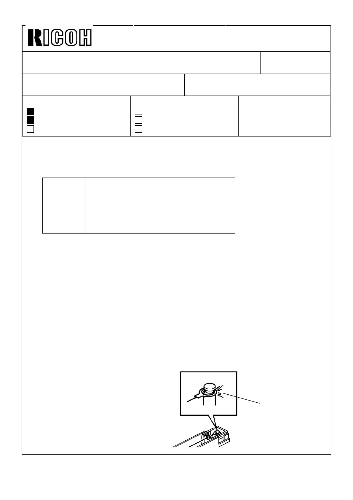
The corona discharge causes ammonium nitrate (NH4NO3) to accumulate on the corona
casing.
NH4NO3 functions as an insulator that reduces the corona discharge to the casing. The
power pack responds by increasing the voltage to the corona wire in order to maintain a
constant current output. (The power pack is a constant current type.)
If toner or some other material accumulates inside the corona end block especially inside
the hook groove [A], it may cause an electrical leak under humid conditions.
NH4NO3 can be easily removed with water but not with alcohol. Toner can be easily
removed with alcohol but not with water.
Therefore, be careful to use the proper cleaning method for each corona unit section.
[A]
Page 2

Technical Bulletin No. RTB-005
REVISED ON APRIL 15, 1991
SUBJECT: Cleaning Solutions DATE: Dec. 30, ’90
PAGE: 1 of 1
PREPARED BY: T. OKAJIMA
CHECKED BY:
CLASSIFICATION:
Action Required
Troubleshooting
Retrofit Information
Based upon the request from the market, three type of cleaning solution have been
registered as service parts. Please order them from the parts center as usual. The details
are as follows:
Revision of service manual
Information only
Other
FROM: International Q.A. Center
MODEL: General
1. EXTERIOR COVER CLEANER (NET. 220 cc)
P/N: A0129530
Purpose: 1) To clean the exterior covers
2) To remove spilt silicone oil from the floor
Procedure: 1) Shake well and spray onto the soiled cover or on the floor.
2) After 10 seconds, wipe cleaner using a soft cloth.
2. DF BELT CLEANER (NET. 180 cc)
P/N: A0129531
Purpose: To clean document feeder belts.
Procedure: 1) Dampen a soft cloth with the cleaner, and wipe the belt.
2) Repeat until the belt is clean.
3. Optics Cleaner (NET. 190 cc)
P/N: A0129532
Purpose: To clean mirrors, lenses, exposure glasses, and paper feed rollers
Procedure: Dampen a soft cloth with the cleaner, and wipe the soiled parts.
CAUTION
Since these three type of cleaning solution are FLAMMABLE, pay attention to the
following caution:
1. Do not spray onto bare skin.
2. Keep away from heat and open flame.
3. Store in a cool place.
4. Keep away from children.
5. Do not dispose of the cleaner by burning it, by applying heat to it, or by any
means that might cause it to ignite.
6 Comply with all local regulations for disposal.
Page 3

Technical Bulletin No. RTB-006
SUBJECT: New Tri-flow Lubricant DATE: Jan 15, 91
PAGE: 1 of 1
PREPARED BY: N. Takai
CHECKED BY:
CLASSIFICATION:
Action Required
Troubleshooting
Retrofit Information
To protect the environment, the tri-flow lubricant (P/No. 52159533) that uses CFC aerosol
propellants has been discontinued. A new tri-flow that uses LPG as the propellant is now
being supplied.
NOTE: CFC (chlorofluorocarbon) gasses are believed to contribute to the depletion of the
earth’s ozone layer.
New Tri-flow: P/No.: 52159539 (Volume: 27 ml)
Revision of service manual
Information only
Other
FROM: Copier Technical Support Section
MODEL: General
Page 4
Technical Bulletin No. RTB-008
SUBJECT: Ground Sheet DATE: Mar 31,’91
PAGE: 1 of 1
PREPARED BY: M. Ninomiya
CHECKED BY:
CLASSIFICATION:
Action Required
Troubleshooting
Retrofit Information
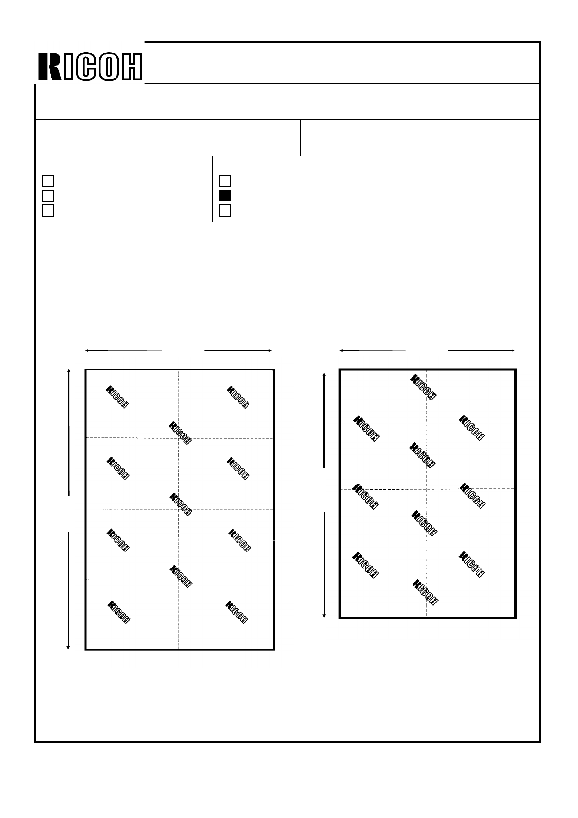
Two different sizes of ground sheets have been registered as service parts.
These sheets help keep the customer’s floor clean by catching any toner, oil, etc, that
may fall to the floor while customer engineer is servicing a copier.
800 mm
Revision of service manual
Information only
Other
FROM: Copier Technical Support Sec.
MODEL: General
650 mm
1200
mm
920
mm
Small(Green) (P/N A0099019)
Large (Gray) (P/N A0099017)
Page 5

Technical Bulletin No. RTB-009
SUBJECT: Service Parts Package Improvement DATE: Mar. 31, ’92
PAGE: 1/1
PREPARED BY: N. Takai
CHECKED BY:
CLASSIFICATION:
Action Required
Troubleshooting
Retrofit Information
The earth is a closed environment with limited resources. People need a good
environment, where they can live safely and comfortably. We, Ricoh as a manufacturer,
believe that protecting the environment and passing on a better environment to posterity is
one of the most important duties of every living being.
In live with the above concept, we are improving not only the machines, but even the
packages for the service parts to help preserve the environment as follows:
Schedule for improvement of service parts packaging
Step 1: Elimination of plastic made from Polyvinyl chloride (PVC) Feb. ’92
Revision of service manual
Information only
Other
Item From (target)
FROM: Copier Technical Support Sec.
MODEL: General
Step 2: Elimination of glueing different materials together Aug. ’92
(i.g. styrofoam and cardboard)
* This is to facilitate segregating the waste by material.
Step 3: Reduction of usage of cardboard(10% less) Sep. ’92
* This is to reduce wasting resources.
This bulletin covers all package changes for service parts related to the preservation of the
environment. We will not inform you of the changes for individual parts packages.
Page 6

RICOH Technical
Bulletin
PAGE: 1/4
Model:
Subject:
From:
Classification:
Some service tools were set up as service parts decades ago for cases where appropriate
field service tools could not be obtained locally. These tools will no longer be available at
the SPC.
This is because all types of service tools are now available across the world. Also, some
tools are no longer needed for servicing recent Ricoh products.
The target service tools are listed on the following pages.
General
Service Tools
QAC Field Information Dept.
Troubleshooting
Mechanical
Paper path
Other ( )
Part information
Electrical
Transmit/receive
Date:
30-Sep-98
Prepared by:
No.:
1
M.Mimura
Action required
Service manual revision
Retrofit information
Page 7

RICOH Technical
Bulletin
PAGE: 2/4
Model:
General
Date:
30-Sep-98
No.:
1
TOOL LIST – 115V (54199 901)
Item Part No. Description Q’ty Item Part No. Description Q’ty
1. 54199600 Tool Case (Aluminum) 1 31. 54199630 Screw Driver Long Shawk “+” 75mm 1
2. 54199601 Tension Gauge 0-2Kg 1 32. 54199631 Voltage Checler-100V 250V 1
3. 54199602 Wrench 1 33. 54199632 Cleaner-Solder Iron 1
4. 54199603 Thickness Gauge 1 34. 54199633 Solder 1
5. 54199604 File 1 set 35. 54199634 NT Cutter 1
6. 54199605 Parts Case 1 36. 54199635 Tester 1
7. 54199606 Oiler 2 pcs. 37. 54199636 Solder Sucker 1
8. 54199607 Bond 1 38. 54199637 Electric Torch-Pen type 1
9. 54199608 Crimping Plier 1 39. 54199638 Retaining Ring Holder-1.5mm 1
10. 54199609 Wire Stripper 1 40. 54199639 Retaining Ring Holder-2.0mm 1
11. 54199610 Magnetic Screw Driver 1 41. 54199640 Retaining Ring Holder-2.5mm 1
12. 54199611 Nipper 1 42. 54199641 Retaining Ring Holder-3.0mm 1
13. 54199612 Cutting Plier-Radio Type 1 43. 54199642 Retaining Ring Holer-4.0mm 1
14. 54199613 Cutting Plier 1 44. 54199643 Retaining Ring Holder-5.0mm 1
15. 54199614 Plier 1 45. 54199644 Retaining Ring Holder-6.0mm 1
16. 54199615 Tweezers 1 46. 54199645 Retaining Ring Holder-7.1mm 1
17. 54199616 Allen Erench-1.5mm 1 47. 54199646 Retaining Ring Holder-8.1mm 1
18. 54199617 Allen Wrench-2.0mm 1 48. 54199647 Scale-150mm 1
19. 54199618 Allen Wrench-2.5mm 1 49. 54199648 Crescent Wrench 1 set
20. 54199619 Allen Wrench-3.1mm 1 50. 54199649 Insulating Tape-Black 1
21. 54199620 Allen Wrench-4.0mm 1 51. 54199650 Insulating Tape-Red 1
22. 54199621 Allen Wrench-5.0mm 1 52. 54199651 Double Coated Tape 1
23. 54199622 Allen Wrench-6.0mm 1 53. 54199652 Silicon Cloth 1
24. 54199623 Allen Wrench-8.0mm 1 54. 54199653 Spring Hook 1
25. 54199624 Screw Driver ”-“ 120mm 1 55. 54199654 Test Chart-B4 size 1
26. 54199625 Screw Driver “+” 120mm 1 56. 54199655 Test Chart-A3 size 1
27. 54199626 Screw Driver “+” 125mm 1 57. 54199656 Solder Tip 1
28. 54199627 Stubby Screw Driver “-“ 1 58. 54199657 Solder Iron –115V 1
125mm
29. 54199628 Stubby Driver “+” 1 59. 54199706 Clip Ass’y-Large 1
30. 54199629 Screw Driver Long Shawk 1 60. 54199707 Clip Ass’y-Small 1
“-“ 125mm
61. 54086001 Service Mat 1
Page 8

RICOH Technical
Bulletin
PAGE: 3/4
Model:
General
Date:
30-Sep-98
No.:
1
TOOL LIST – 220V (54199 902)
Item Part No. Description Q’ty Item Part No. Description Q’ty
1. 54199600 Tool Case (Aluminum) 1 31. 54199630 Screw Driver Long Shawk “+” 75mm 1
2. 54199601 Tension Gauge 0-2Kg 1 32. 54199631 Voltage Checler-100V 250V 1
3. 54199602 Wrench 1 33. 54199632 Cleaner-Solder Iron 1
4. 54199603 Thickness Gauge 1 34. 54199633 Solder 1
5. 54199604 File 1 set 35. 54199634 NT Cutter 1
6. 54199605 Parts Case 1 36. 54199635 Tester 1
7. 54199606 Oiler 2 pcs. 37. 54199636 Solder Sucker 1
8. 54199607 Bond 1 38. 54199637 Electric Torch-Pen type 1
9. 54199608 Crimping Plier 1 39. 54199638 Retaining Ring Holder-1.5mm 1
10. 54199609 Wire Stripper 1 40. 54199639 Retaining Ring Holder-2.0mm 1
11. 54199610 Magnetic Screw Driver 1 41. 54199640 Retaining Ring Holder-2.5mm 1
12. 54199611 Nipper 1 42. 54199641 Retaining Ring Holder-3.0mm 1
13. 54199612 Cutting Plier-Radio Type 1 43. 54199642 Retaining Ring Holer-4.0mm 1
14. 54199613 Cutting Plier 1 44. 54199643 Retaining Ring Holder-5.0mm 1
15. 54199614 Plier 1 45. 54199644 Retaining Ring Holder-6.0mm 1
16. 54199615 Tweezers 1 46. 54199645 Retaining Ring Holder-7.1mm 1
17. 54199616 Allen Erench-1.5mm 1 47. 54199646 Retaining Ring Holder-8.1mm 1
18. 54199617 Allen Wrench-2.0mm 1 48. 54199647 Scale-150mm 1
19. 54199618 Allen Wrench-2.5mm 1 49. 54199648 Crescent Wrench 1 set
20. 54199619 Allen Wrench-3.1mm 1 50. 54199649 Insulating Tape-Black 1
21. 54199620 Allen Wrench-4.0mm 1 51. 54199650 Insulating Tape-Red 1
22. 54199621 Allen Wrench-5.0mm 1 52. 54199651 Double Coated Tape 1
23. 54199622 Allen Wrench-6.0mm 1 53. 54199652 Silicon Cloth 1
24. 54199623 Allen Wrench-8.0mm 1 54. 54199653 Spring Hook 1
25. 54199624 Screw Driver ”-“ 120mm 1 55. 54199654 Test Chart-B4 size 1
26. 54199625 Screw Driver “+” 120mm 1 56. 54199655 Test Chart-A3 size 1
27. 54199626 Screw Driver “+” 125mm 1 57. 54199656 Solder Tip 1
28. 54199627 Stubby Screw Driver “-“ 1 58. 54199658 Solder Iron –220V 1
125mm
29. 54199628 Stubby Driver “+” 1 59. 54199706 Clip Ass’y-Large 1
30. 54199629 Screw Driver Long Shawk 1 60. 54199707 Clip Ass’y-Small 1
“-“ 125mm
61. 54086001 Service Mat 1
Page 9

RICOH Technical
Bulletin
PAGE: 4/4
Model:
General
Date:
30-Sep-98
No.:
1
TOOL LIST – 240V (54199 903)
Item Part No. Description Q’ty Item Part No. Description Q’ty
1. 54199600 Tool Case (Aluminum) 1 31. 54199630 Screw Driver Long Shawk “+” 75mm 1
2. 54199601 Tension Gauge 0-2Kg 1 32. 54199631 Voltage Checler-100V 250V 1
3. 54199602 Wrench 1 33. 54199632 Cleaner-Solder Iron 1
4. 54199603 Thickness Gauge 1 34. 54199633 Solder 1
5. 54199604 File 1 set 35. 54199634 NT Cutter 1
6. 54199605 Parts Case 1 36. 54199635 Tester 1
7. 54199606 Oiler 2 pcs. 37. 54199636 Solder Sucker 1
8. 54199607 Bond 1 38. 54199637 Electric Torch-Pen type 1
9. 54199608 Crimping Plier 1 39. 54199638 Retaining Ring Holder-1.5mm 1
10. 54199609 Wire Stripper 1 40. 54199639 Retaining Ring Holder-2.0mm 1
11. 54199610 Magnetic Screw Driver 1 41. 54199640 Retaining Ring Holder-2.5mm 1
12. 54199611 Nipper 1 42. 54199641 Retaining Ring Holder-3.0mm 1
13. 54199612 Cutting Plier-Radio Type 1 43. 54199642 Retaining Ring Holer-4.0mm 1
14. 54199613 Cutting Plier 1 44. 54199643 Retaining Ring Holder-5.0mm 1
15. 54199614 Plier 1 45. 54199644 Retaining Ring Holder-6.0mm 1
16. 54199615 Tweezers 1 46. 54199645 Retaining Ring Holder-7.1mm 1
17. 54199616 Allen Erench-1.5mm 1 47. 54199646 Retaining Ring Holder-8.1mm 1
18. 54199617 Allen Wrench-2.0mm 1 48. 54199647 Scale-150mm 1
19. 54199618 Allen Wrench-2.5mm 1 49. 54199648 Crescent Wrench 1 set
20. 54199619 Allen Wrench-3.1mm 1 50. 54199649 Insulating Tape-Black 1
21. 54199620 Allen Wrench-4.0mm 1 51. 54199650 Insulating Tape-Red 1
22. 54199621 Allen Wrench-5.0mm 1 52. 54199651 Double Coated Tape 1
23. 54199622 Allen Wrench-6.0mm 1 53. 54199652 Silicon Cloth 1
24. 54199623 Allen Wrench-8.0mm 1 54. 54199653 Spring Hook 1
25. 54199624 Screw Driver ”-“ 120mm 1 55. 54199654 Test Chart-B4 size 1
26. 54199625 Screw Driver “+” 120mm 1 56. 54199655 Test Chart-A3 size 1
27. 54199626 Screw Driver “+” 125mm 1 57. 54199656 Solder Tip 1
28. 54199627 Stubby Screw Driver “-“ 1 58. 54199659 Solder Iron –240V 1
125mm
29. 54199628 Stubby Driver “+” 1 59. 54199706 Clip Ass’y-Large 1
30. 54199629 Screw Driver Long Shawk 1 60. 54199707 Clip Ass’y-Small 1
“-“ 125mm
61. 54086001 Service Mat 1
Page 10

RICOH Technical
Bulletin
PAGE: 1/1
Model:
Subject:
From:
Classification:
This bulletin is a general service reminder.
Do not do any of the following in the field under any circumstances.
1. Disable safety devices such as thermofuses and thermistors.
2. Use the wrong safety devices such as thermofuses and thermistors.
General
General Service Remarks for Safety
GTSS Field Information Dept.
Troubleshooting
Mechanical
Paper path
Other ( )
CAUTION
Part information
Electrical
Transmit/receive
Date:
31-Dec-98
Prepared by:
M. Mimura
Action required
Service manual revision
Retrofit information
No.:
2
3. Swap different types of fusing units across different models.
If the wrong type of fusing unit is used, the thermofuse may not work properly.
These points all affect product safety.
Please always use the correct parts as shown in the parts catalog for the product.
Page 11
RICOH Technical
Bulletin
PAGE: 1/1
Model:
Subject:
From:
Classification:
The new FCC regulations will be applied to products produced after December 19, 1999.
The following features will be affected by these changes and the firmware changed accordingly.
- Redialing -
Limited to only one time if the machine cannot detect the busy and re-order tones.
- Transmission Deadline function (TRD) -
The maximum number of times for redialing is limited to 14. Therefore, this function will not be
available.
- Affected machines -
Product
Fax
LFO NO 4 NO NO 1 NO
FR6, FR4 NO 4 YES NO 1 NO
Schmidt3 YES 4 YES YES 4 NO
Schmidt1 NO 1 NO NO 1 NO
Kaiser1 No production YES 4 NO *1, *3
Digital PPC
NAD NO 4 YES NO 1 NO
Stinger-C1 NO 1 YES YE 4 NO
Russian-C1 NO 1 NO YES 4 NO *3
GF10B NO 2 NO NO 1 NO *2
Digital Color
Lilac2 No production NO 1 NO *1
Option
S G3 Option NO 4 - NO 1 NO *3, *4
Note:
*1: The change will be applied from the first lot of mass-production.
*2: No memory transmission is available.
*3: When this option is installed, redialing from the main frame is also limited to one time.
*4: TRD is controlled by the main frame.
For details of these changes, please refer to the MB or RTB that will be issued for each model.
Products with FAX function (US version)
For New FCC Regulations
Technical Servers Dept., GTS Division
Troubleshooting
Mechanical
Paper path
Other ( )
Before change After change
Tone
detection
Redialing TRD Tone
Part information
Electrical
Transmit/receive
detection
Date:
30-Nov-99
Prepared by:
Redialing TRD
Action required
Service manual revision
Retrofit information
No.:
Y. Okunishi
Note
RGene003
Page 12

T
echnical
B
ulletin
PAGE: 1/17
Model:
Subject:
From:
Classification:
The new software will be released for the CiG4 unit to provide new functions for ISDN
comunication. This RTB clarifies the new switches and their software version.
Please note that the CiG4 unit is being used in the FX4 and FR4 fax machines, and in the
Adam, NAD, Stinger-C , and Russian-C copiers.
NOTE:
The software versions which enable each switch are listed in the “NOTE” column.
Otherwise, functions are available from the first production of the G4 unit for the above
machines.
Release date:
Version 0B: ’97. November (at the same time as the fax FR4 release)
Version 0F: ’00. March
General
CiG4 Switches and Software Versio n
Technical Services Dept., GTS Division
Troubleshooting
Mechanical
Paper path
Other ( )
Part information
Electrical
Transmit/receive
Date:
31-Jan-00
Prepared by:
No.:
RGene004
K. Misugi
Action required
Service manual revision
Retrofit information
WARNING
Do not adjust a bit switch that is described as "Not used", as this may
cause the machine to malfunction or to operate in a manner that is not
accepted by local regulations.
Important:
In the CiG4 unit, after changing any of the bit switches, turn off the machine, wait for 5
seconds or more, and turn it back on, so that the new settings take effect.
1. G4 Internal Switches
Bit Switch 00
FUNCTION COMMENTS NOTE
Country code
Bit 4 3 2 1 0 Country
0
0 0 0 0 1 Germany (1TR6 mode)
to
0 0 0 1 0 Universal (Europe Euro ISDN)
7
1 0 0 0 1 USA
1 1 0 1 1 Taiwan
Note:
In Germany, use the Universal setting for the Euro ISDN lines.
In Taiwan, use the Taiwan setting for firmware version 0D or later.
Bit switches 01 and 02 are not used. Do not change the settings.
Page 13

T
echnical
B
ulletin
PAGE: 2/17
Model:
Bit Switch 03
1-7
Bit Switch 04
0-2
6-7
General
Amount of protocol dump data
in one protocol dump list
0:
0
3
4
5
Last communication only
1:
Up to the limit of the
memory area for protocol
dumping
Not used Do not change the settings.
Not used Do not change the settings.
Auto data rate change for
transmission
(64 kbps to 56 kbps)
0:
On
1:
Off
Auto data rate change for
reception (64 kbps to 56 kbps)
0:
Off
1:
On
RCBCTR
0:
Not valid
Not used Do not change the settings.
Date:
FUNCTION COMMENTS NOTE
Change this bit to 0 if you want to have a
protocol dump list of the last communication
only.
This bit is only effective for the dump list D +
Bch1.
FUNCTION COMMENTS NOTE
0:
The machine automatically changes the
transmission data rate from 64 kbps to 56
kbps after 3 s if the other end did not accept
the call. This is to cope with 56 kbps
networks in the USA.
Normally, keep this bit at 0.
1:
The machine automatically changes the
reception data after 6 s.
Change this bit to 1 only when there is a
communication error where the other terminal
informs 64 kbps in the SETUP signal
although it is actually 56 kbps.
This bit is used in Germany; set it to 1 for
1:
Valid
German FTZ approval tests.
1:
RCBCTR counts consecutive R:RNR
signals. If the counter reaches the value of
N2, the link is disconnected.
31-Jan-00
No.:
RGene004
Bit Switch 05
0
Not used Do not change the settings.
Logical channel number (LCN)
0:
Not controlled
1
1:
Fixed at 01
Protocol ID check
2
0:
Yes
3-7
Not used Do not change the settings.
FUNCTION COMMENTS NOTE
Keep this bit normally at 0. However, some
networks may require a fixed LCN. In such
cases, this bit should be 1, and you may have
to set a different value for the LCN using G4
Parameter Switch A.
The Protocol ID is in the CR packet.
1:
No
Page 14

T
echnical
B
ulletin
PAGE: 3/17
Model:
Bit Switch 06
2-7
Bit switch 07 and 08 are not used.
Bit Switch 09
2-7
General
FUNCTION COMMENTS NOTE
Inclusion of the DTE address
in the S:CR packet
0:
0
Calling and called DTE
addresses
1
0:
Not used Do not change the settings.
0
Not used Do not change the settings.
New session within the same
call
1
0:
1:
Not used Do not change the settings.
1:
No
Not used
Not accepted
Accepted
Yes
1:
FUNCTION COMMENTS NOTE
Used
Date:
Normally, do not change the setting.
When the CR packet format matches
ISO8208 protocol, some networks may
require this bit to be set at 1.
This bit is only effective if bit 0 of G4
Parameter switch 6 is at 0.
Normally, do not change the setting.
This is only for packet networks. The CR
packet should contain the rx side's DTE
address, but does not have to include the tx
side's; it can include it as an option.
0:
If a new R:CSS is received, the machine
sends back S:RSSN.
1:
If a new R:CSS is received, the machine
sends back S:RSSP. Set this bit to 1 for
German PTT (FTZ) approval tests.
31-Jan-00
No.:
RGene004
Bit switches 0A to 0F are not used. Do not change the settings.
Page 15

T
echnical
B
ulletin
PAGE: 4/17
Model:
Bit Switch 10
4-5
General
0
Not used Do not change the settings.
Layer 1 T3 timer
Bit 2 1 Time
1
0 0 5 s
0 1 29 s
2
1 0 10 s
1 1 Not used
Layer 1 T4 timer
3
0:
Not used
Not used Do not change the settings.
INFO1 signal resend
0: Resend
6
1: No resend
Loop back 4 mode
7
0:
Disabled
Date:
FUNCTION COMMENTS NOTE
This should be kept at 5 s (both bits at 0) for
normal operation.
Set this bit to 1 for French PTT approval
1:
Used
1:
Enabled
tests.
0: Some DSUs may not reply to the INFO1
signal with INFO2, if there is noise in the
INFO1 signal accidentally. Try changing this
bit to 0, to resend INFO1 before the machine
displays “CHECK INTERFACE”.
Normally, keep this bit at 0.
31-Jan-00
No.:
RGene004
Bit Switch 11
FUNCTION COMMENTS NOTE
0
Not used Do not change the settings.
Type of TEI used
0:
Dynamic TEI
1
1:
Static TEI
Static TEI value
2
7
This is normally fixed at 0. However, some
networks such as the Northern Telecom
ISDN may require this bit to be set at 1 (see
below). In this case, you may have to change
the values of bits 2 to 7.
This is used in the USA with the DMS100
(Northern Telecom ISDN) exchanger.
Store the lowest bit of the TEI at bit 7 and the
highest bit of the TEI at bit 2.
Example:
3 and 4 to 1 and bits 2, 5, 6, and 7 to 0.
If the static TEI is 011000, set bits
Bit switch 12 is not used. Do not change the settings.
Page 16

T
echnical
B
ulletin
PAGE: 5/17
Model:
Bit Switch 13
0-1
General
Not used Do not change the settings.
Attachment of calling ID
0:
No
2
Attachment of the Lower Layer
Capabilities
3
0:
No
Attachment of the Higher
Layer Capabilities
4
0:
Yes
Attachment of the channel
5
information element (CONN)
0:
No
Attachment of the Higher
Layer Capabilities for ISDN G3
transmission
0:
Same as the bit 4 setting
6
1:
Not attached
Condition for fallback from G4
to G3
0:
Refer to the CPS code
setting
1:
7
Fallback in response to any
CPS code
Date:
FUNCTION COMMENTS NOTE
Normally, this bit should be at 0, because
1:
1:
1:
1:
Yes
Yes
No
Yes
most networks add the calling ID to the
SETUP signal to the receiver.
However, some networks may require the
machine to add this ID. Only in this case
should this bit be at 1.
This bit determines whether Lower Layer
Capabilities are informed in the [SETUP]
signal.
Keep this bit at 0 in most cases.
This bit determines whether Higher Layer
Capabilities are informed in the [SETUP]
signal or not.
Keep this bit at 0 in most cases.
Keep this bit at 0 in most cases.
This bit determines whether Higher Layer
Capabilities are informed in the [SETUP]
signal for ISDN G3 transmission. This switch
is effective in coping with communication
problems with some types of T/A and PBX
which do not respond to Higher Layer
Capability “G3.”
When this bit is set to 0, the setting depends
on the setting of bit 4.
0:
Fallback occurs when a CPS code is the
same as the CPS code settings specified by
G4 internal switches 17, 18, 1A, 1B, and 1C.
If you wish to enable fallback when any CPS
code is detected, set this bit to “1.”
This switch is effective in coping with fallback
problems where the CPS code does not
match those specified in the ITU-T
recommendation.
31-Jan-00
No.:
RGene004
Ver. 0B
Ver. 0F
NOTE:
CiG4 software version 0F will be released from ’00. March production.
Page 17

T
echnical
B
ulletin
PAGE: 6/17
Model:
Bit Switch 14
1-2
General
ISDN G3 information transfer
capability
0:
3.1 kHz audio
1:
0
3
4
5
6
7
Speech
Not used Do not change the settings.
Channel selection in [SETUP]
in tx mode
Bit 4 3 Setting
0 0 Any channel
0 1 B1 channel
1 0 B2 channel
1 1 Not used
Called ID mapping
0:
Called party number
1:
Keypad facility
Numbering plan for the called
party number
0:
Unknown
1:
E.164
Subaddress coding type
0:
IA5 (NSAP)
1:
BCD (ISO8348)
Date:
FUNCTION COMMENTS NOTE
In tx mode, this determines the information
transfer capability informed in the [SETUP]
message.
In rx mode, this determines the information
transfer capability that the machine can use
to receive a call.
Set this bit to 1 if the ISDN does not support
3.1 kHz audio.
Any channel:
exchanger, the exchanger will select either
B1 or B2.
0:
Called ID is mapped to the called party
number.
1:
Called ID is mapped to the keypad facility.
On the 5ESS network (USA), set it to 1.
E.164:
AXE10 exchanger is fitted with old software,
and in Australia.
Unknown:
This is normally kept at 0. However, some
networks require this bit to be at 1.
This may be used in Sweden if an
When this is informed to the
This is the normal setting.
31-Jan-00
No.:
RGene004
Page 18

T
echnical
B
ulletin
PAGE: 7/17
Model:
Bit Switch 15
1-3
6-7
General
Action when receiving a
[SETUP] signal containing no
called subaddress, if the
0
subaddress was programmed
in the dialed number
0:
A reply is sent
1:
No reply is sent
Not used Do not change the settings
Action when the received
Higher Layer Capabilities is
Tel or Bearer Capabilities is
4
Speech
0:
Do not respond to the call
1:
Respond to the call
Global call reference
0:
Ignored
5
1:
Global call number is used
Not used Do not change the settings.
Date:
FUNCTION COMMENTS NOTE
This bit depends on user requirements. If it is
at 1, communication will be halted if the other
terminal has not input the subaddress.
1:
This switch is effective in coping with
communication problems when the received
Higher Layer Capabilities is Tel or Bearer
Capabilities is Speech for ISDN G3
communication.
Global call reference means 'call reference
value = 0'. This bit determines how to deal
with such an incoming call if received from
the network.
Keep this bit at 1 for Germany 1TR6.
31-Jan-00
No.:
RGene004
Ver. 0B
Page 19

T
echnical
B
ulletin
PAGE: 8/17
Model:
Bit Switch 16
3-4
General
Answer delay time
Bit 1 0 Setting
0 0 No delay
0 1 1.0 s delayed (1TR6)
1 0 0.5 s delayed
1 1 Not used
0
1
Action when receiving a
[SETUP] signal containing
user-specific called party
subaddress
0:
2
5
6
7
Ignores the call
1:
Receives the call
Not used Do not change the settings.
Indicated bearer capabilities
0:
56 kbps
Not used Do not change the settings.
Transfer capabilities (SI)
informed in 1TR6 ISDN G3
transmission
0:
G3 Fax
1:
Analog
Date:
FUNCTION COMMENTS NOTE
For Germany 1TR6, a time delay for
answering calls is required.
In other countries, use this switch as follows:
If the machine is connected to the same bus
from the DSU as a model K200 is connected,
the machine receives most of the calls
because the response time to a call is faster
than the K200.
If the customer wants the K200 to receive
most of the calls, adjust the response time
using these bits.
If the customer does not want one machine to
receive most of the calls, use subaddresses
to identify each terminal.
Normally, the 3rd octet of called party
subaddress information in the [SETUP] signal
is set to NSAP. However, some networks
may add a “user-specific” subaddress to the
[SETUP] signal, and as a result the machine
won't answer the call if a subaddress is
specified.
So, change this bit to 1 to let the machine
receive the call if the machine is connected to
such a network.
1:
64 kbps calling is indicated in the Bearer
1:
64 kbps
Capabilities, but communication is at 56 k.
Use this bit if the machine is connected to a
network which does not accept a 56 kbps
data transfer rate as a bearer capability.
This bit determines the transfer capabilities
informed in the Service Indicator for 1TR6
ISDN G3 transmission. This switch is
effective in coping with communication
problems with some types of T/A and PBX.
31-Jan-00
No.:
RGene004
Page 20

T
echnical
B
ulletin
PAGE: 9/17
Model:
Bit Switch 16
0-6
General
Condition for fallback from G4 to G3
Bits 0 to 6 of bit switch 17 contain a CPS code, and bits 0 to 6 of bit switch 18
contain another CPS code. If a CPS code is received which is the same as
either of these, communication will fall back from ISDN G4 mode to ISDN G3
mode.
The CPS codes must be the same as those specified in table 4-13 of CCITT
recommendation Q.931.
Examples: Bit 6 5 4 3 2 1 0
For the codes in bits 0 to 6 of bit switches 17 and 18 to be recognized, bit 7 of
bit switch 17 must be 1. Also, bit 0 of the Communication Switch 07 must be at
0, or Fallback from G4 to G3 will be disabled.
This bit determines whether fallback from G4 to G3 occurs on receipt of one of
the CPS codes programmed in bit switch 17 or 18, or on receipt of a certain
standard code.
0:
Fallback occurs on receipt of any of the following CPS codes:
7
Universal (Euro ISDN) - #3, #18, #57, #58, # 63, # 65, #79, #88, and #127
Germany 1TR6 mode - #3, #53, #58, and #90
Others - #3, #65, and #88
1:
Fallback from G4 to G3 occurs on receipt any of above CPS codes or one of
the CPS codes programmed in bit switch 17, 18, 1A, 1B, or 1C
Date:
FUNCTION COMMENTS NOTE
1 0 0 0 0 0 1 CPS code 65
1 0 1 1 0 0 0 CPS code 88
31-Jan-00
No.:
RGene004
Bit Switch 18
FUNCTION COMMENTS NOTE
Condition for fallback from G4 to G3
0-6
See the explanation for bits 0 to 6 of bit switch 17
This bit helps to choose the CPS code set for G4 to G3 fallback.
0:
Fallback occurs on receipt of the CPS code set which is specified by the
country code setting.
7
1:
Fallback occurs on receipt of the Universal CPS code set (#3, #18, #57, #58,
# 63, # 65, #79, #88, and #127) even if another country code is programmed.
If bit switch 17 bit 7 is “1”, fallback occurs on receipt of the Universal CPS code
set or one of the CPS codes programmed in bit switches 17, 18, 1A, 1B, or 1C.
G4 to G3 fallback
Bit 0 of Communication Switch 07 must be at 0, or fallback from G4 to G3 will be disabled.
The CPS codes for which fallback occurs are decided as follows.
G4 bit switch 17, bit 7 - If set to “0”, fallback occurs on receipt of a code from a set that
•
depends on the country code. If set to ”1”, fallback occurs for the 5 CPS codes
programmed in bits 0 to 6 of G4 bit switches 17, 18, 1A, 1B, and 1C, in addition to the
country code set.
Page 21

T
echnical
B
ulletin
PAGE: 10/17
Model:
Bit Switch 19
2-7
Bit Switch 1A: CPS Code Used for G4 to G3 Fallback - 3
0-6
Bit Switch 1B: CPS Code Used for G4 to G3 Fallback - 4
0-6
General
FUNCTION COMMENTS NOTE
Permanence of the link
0:
0
1
7
7
Set/released each LAPD
call
1:
Permanent
Channel used in ISDN L2
(64k) mode
0:
B1 1: B2
Not used Do not change the factory settings.
FUNCTION COMMENTS NOTE
Condition for fallback from G4 to G3
See the explanation for bits 0 to 6 of bit switch 17.
Not used Do not change the factory settings.
FUNCTION COMMENTS NOTE
Condition for fallback from G4 to G3
See the explanation for bits 0 to 6 of bit switch 17.
Not used Do not change the factory settings.
Keep this at 1 in the USA. In other areas, this
bit is normally 0, depending on network
requirements.
When making an IDSN L2 back-to-back test,
you can select either the B1 or B2 channel
with this bit switch.
Date:
31-Jan-00
No.:
RGene004
Bit Switch 1C: CPS Code Used for G4 to G3 Fallback - 5
FUNCTION COMMENTS NOTE
Condition for fallback from G4 to G3
0-6
See the explanation for bits 0 to 6 of bit switch 17.
7
Not used Do not change the factory settings.
Bit switches 1D to 1F are not used. Do not change any of the settings.
Page 22

T
echnical
B
ulletin
PAGE: 11/17
Model:
General
2. G4 Parameter Switches
Parameter Switch 00
FUNCTION COMMENTS NOTE
0
Network typ e
Bit 2 1 0 Type
1
x 0 0 Circuit switched
ISDN
2
Other settings: Not used
3-7
Not used Do not change the default settings.
Parameter Switch 01
FUNCTION COMMENTS NOTE
Voice coding
0
0:
µ law
1:
A law
Action when a [SETUP] signal
without HLC is received
0:
1
2-3
4
5
6
7
Respond to the call
1:
Not respond to the call
Not used Do not change the default settings.
Signal attenuation level for G3 fax signals received from an ISDN line.
If an analog signal comes over an digital line, the signal level after decoding by
the TE is theorically the same as the level at the entrance to the digital line.
However, this sometimes causes the received signal level to be too high at the
received end. In this case, adjust the decoded signal's attenuation level using
these switches.
The values in the “Codec” column below show the attenuation level at the G4
interface board. The values in the “Modem” column show the actual attenuation
level at the modem, because the signal is attenuated again on the MFCE by 6dB.
Bit 6 5 4 Codec Modem (Actual attenuation level)
0 0 0 -4.5dB -10.5dB
0 0 1 -2.5dB -8.5dB
0 1 0 -0.5dB -6.5dB
0 1 1 +1.5dB -4.5dB (default sett ing)
1 0 0 +3.5dB -2.5dB
1 0 1 +5.5dB -0.5dB
1 1 0 +7.5dB +1.5dB
1 1 1 +9.5dB +3.5dB
Not used Do not change the default settings.
Date:
Do not change the default setting.
0:
This setting is used in USA.
1:
This setting is used in Europe and Asia.
If there are several TEs on the same bus and
the machine responds to calls for another TE,
the call may be without HLC information.
Identify the type of calling terminal and
change this bit to 1 if the caller is not a fax
machine.
31-Jan-00
No.:
RGene004
Page 23

T
echnical
B
ulletin
PAGE: 12/17
Model:
Parameter Switch 02
2-3
6-7
Parameter Switch 03
1-7
General
FUNCTION COMMENTS NOTE
Data rate (kbps)
0
Bit 1 0 Setting
0 0 64 kbps
1
0 1 56 kbps
Not used Do not change the default settings.
Transmission mode
4
Bit 5 4 Mode
5
0 0 CS
Not used Do not change the default settings.
FUNCTION COMMENTS NOTE
Link modulus
0:
0
Not used Do not change the default settings.
8
1:
128
Date:
Other settings: Not used
Normally, do not change the seting.
Keep this bit at 0 in most cases.
This setting determines whether protocol
frame numbering is done using 3 bits (0 to 7
then start again at 0) or 7 bits (0 to 127 then
start again at 0). Set this bit switch to match
the network's specifications.
31-Jan-00
No.:
RGene004
Parameter Switch 04 is not used. Do not change any of the settings.
Parameter Switch 05
FUNCTION COMMENTS NOTE
Link timer (D-channel layer 2
T1 timer)
0
Bit 3 2 1 0 Value
1
0 0 0 0 0 s
2
0 0 0 1 1 s
3
0 0 1 0 2 s
and so on until
1 0 1 0 10 s
B-channel T3 timer
0:
30s
4
1:
57s
5-7
Not used Do not change the default settings.
Normally, do not change the setting.
The link timer is the maximum allowable time
between sending a protocol frame and
receiving a response frame from the remote
terminal.
1:
This switch is useful when used in
combination with communication switch 07 bit
4. This is to cope with communication
problems where G4 communication fails on
the ISDN B-channel.
Ver. 0F
Page 24

T
echnical
B
ulletin
PAGE: 13/17
Model:
Parameter Switch 06
1-3
5-7
Parameter Switch 07
4-7
General
FUNCTION COMMENTS NOTE
Layer 3 protocol
0:
0
4
0
1
2
3
ISO8208
1:
T.70NULL
Not used Do not change the settings.
Packet modulus
0:
Not used Do not change the settings.
Packet size
Bit 3 2 1 0 Value
0 1 1 1 128
1 0 0 0 256
1 0 0 1 512
1 0 1 0 1024
1 0 1 1 2048
Not used Do not change the settings.
8
1:
128
FUNCTION COMMENTS NOTE
Date:
Set this bit to match the type of layer 3
signalling used by the ISDN.
The dedicated parameters have the same
setting for specific destinations.
Do not change the default setting, unless the
machine is experiencing compatibility
problems.
This value is sent in the CR packet. This
value must match the value stored in the
other terminal, or communication will stop (CI
will be returned). If the other end returns CI,
check the value of the packet window size
with the other party.
Note that this value must be the same as the
value programmed for the transport block
size (G4 Parameter Switch 0B, bits 0 to 3).
Normally, do not change the default setting.
31-Jan-00
No.:
RGene004
Parameter Switch 08
FUNCTION COMMENTS NOTE
Packet window size
0
Bit 3 2 1 0 Value
1
0 0 0 1 1
2
0 0 1 0 2
3
and so on until
1 1 1 1 15
4-7
Not used Do not change the settings.
Parameter Switch 09
FUNCTION COMMENTS NOTE
LCGN
Bit 3 2 1 0 Value
0
0 0 0 0 0
1
0 0 0 1 1
2
0 0 1 0 2
3
and so on until
1 1 1 1 15
4-7
Not used Do not change the settings.
This is the maximum number of
unacknowledged packets that the machine
can send out before having to pause and wait
for an acknowledgement from the other end.
Normally this should be kept at 7.
Keep the value of the LCGN at 0.
Page 25

T
echnical
B
ulletin
PAGE: 14/17
Model:
Parameter Switch 0A
0-7
Parameter Switch 0B
4-7
General
FUNCTION COMMENTS NOTE
LCN
Bit 7 6 5 4 3 2 1 0 Value
0 0 0 0 0 0 0 1 1
0 0 0 0 0 0 1 0 2
0 0 0 0 0 0 1 1 3
and so on until
1 1 1 1 1 1 1 1 255
FUNCTION COMMENTS NOTE
Transport block size
Bit 3 2 1 0 Value
0
0 1 1 1 128
1
1 0 0 0 256
2
1 0 0 1 512
3
1 0 1 0 1024
1 0 1 1 2048
Not used Do not change the settings.
Date:
Keep at the value of the LCN at 1.
This value must match the value set in the
other terminal. Note that this value must be
the same as the value programmed for the
packet size (G4 Parameter Switch 7, bits 0 to
3). Also, the transport block size is limited by
the amount of memory in the remote terminal.
31-Jan-00
No.:
RGene004
Parameter Switch 0C is not used. Do not change any of the settings.
Parameter Switch 0D
FUNCTION COMMENTS NOTE
Back-to-back test mode
Bit 1 0 Setting
0 0 Off
1 0 ISDN L2 test mode
0
(TE mode)
Other settings - Not used
1
2-7
Not used Do not change the settings.
When doing a back-to-back test or doing a
demonstration without a line simulator, use
these bits to set up one of the machines in
TE mode, and the other in NT mode
Please note that this machine can only be set
to TE mode.
After the test, return both bits to 0.
See "Back-to-back Testing" in the
Troubleshooting section of the srrvice manual
for full details.
Page 26

T
echnical
B
ulletin
PAGE: 15/17
Model:
Parameter Switch 0E
2-7
Parameter Switch 0F is not used. Do not change any of the settings.
General
FUNCTION COMMENTS NOTE
Troubleshooing mode - real
time status codes display
0:
0
Saving frames to the protocol
1
dump list
0:
Not used Do not change the settings.
Off
Off
1:
On
1:
On
If this is switched on, the status codes will be
displayed in the lower two lines of the LCD.
These codes are explained in the
Troubleshooting section (G4CCU Status
Codes) of the service manual.
Change this bit back to 0 after testing.
Keep this bit at 1 normally.
Date:
31-Jan-00
No.:
RGene004
Page 27

T
echnical
B
ulletin
PAGE: 16/17
Model:
General
Date:
31-Jan-00
No.:
RGene004
3. DEDICATED TRANSMISSION PARAMETERS
The following G4 communication parameter bytes have been added for each Quick Dial
and Speed Dial.
Switch 07
FUNCTION NOTE
Data rate Bit 3 2 1 0 Setting
0
1
2
3
4-7
Switch 08
0
1
2
3
4-7
0 0 0 0 64 kbps
0 0 0 1 56 kbps
1 1 1 1 As in Parameter Switch 2, bits 0 and 1
Other settings: Not used
Not used. Do not change the settings.
FUNCTION NOTE
Link modulus Bit 3 2 1 0 Setting
0 0 0 0 Modulo 8
0 0 0 1 Modulo 128
1 1 1 1 As in Par ameter Switch 3, bit 0
Other settings: Not used
Not used. Do not change the settings.
Switch 09
Layer 3 pr otocol Bit 3 2 1 0 Setting
0
1
2
3
4-7
Not used. Do not change the settings.
FUNCTION NOTE
0 0 0 0 IS.8208
0 0 0 1 T.70 NULL
1 1 1 1 As in Parameter Switch 6, bit 0
Other settings: Not used
Page 28

T
echnical
B
ulletin
PAGE: 17/17
Model:
General
Date:
31-Jan-00
No.:
RGene004
4. OTHER RELATED SWITCHES
The following switches have been added to the mainframe switches (or fax board switches
for MFPs), in relation to ISDN G4 communication.
Communication Switch 07
FUNCTION COMMENTS NOTE
0:
Fallback from G4 to G3
reflected in programmed
Quick/Speed dials
3
0:
Fallback enabled (Default)
1:
Always start with G4
Fallback from G4 to G3 when
G4 communication fails on the
4
ISDN B-channel
0:
Fallback disabled (Default)
1:
Fallback enabled
If a communication falls back from G4 to
G3, the machine will always start
transmission with G3 from the next
communication.
1:
The machine will always start to transmit
with G4.
1:
Enable this switch only when G4
communication errors occur because the
exchanger connects G4 calls to the PSTN.
This problem only occurs with some types
of exchanger.
See the
following
table
Software versions for each machine
Communication Switch 07
FUNCTION FX4 FR4 Adam NAD
Fallback from G4 to G3
reflected in programmed
3
Quick/Speed dials
0:
Fallback enabled (Default)
1:
Always start with G4
Fallback from G4 to G3 when
G4 communication fails on
4
the ISDN B-channel
0:
Fallback disabled (Default)
1:
Fallback enabled
N/A: Function is not available
N/A
N/A
Availa-
ble
Availa-
ble
Stinger Russian
N/A N/A Available Available
Ver.
1.75
or later
Ver.
5.01 or
later
Available Available
Page 29

!"#$% M
odification Bulletin
PAGE: 1/1
Model:
Modified Article:
From:
Reason for
Modification:
General
Barrierta JEF552
Technical Service Dept., GTS Division
Parts catalog correction
To facilitate assembly
Part standardization
Old part
number
A0289300 Grease Barrierta JFE55/2 1 - 0
New part
Description Q’ty Int Page Index Note
number
A2579300 Grease Barrierta S552R 0 - 1
Date:
23-May-00
Prepared by:
Vendor change
To improve reliability
Other
O/O Refer to the Special
No.:
MGenM001
T. Itoh
To meet standards
( )
Tools section
The vendor of Grease Barrierta has produced a new type that has no scent. A new part
number has been assigned to this new type.
Page 30

odification Bulletin
M
PAGE: 1/1
Model:
Modified Article:
From:
Reason for
Modification:
General
Silicone Oil
Technical Services Dept., GTS Division
Parts catalog correction
To facilitate assembly
Part standardization
Old part
number
54209550 - Silicone Oil 1-0 O/O - -
- A2579100
- A2579550
New part
number
Description Q’ty Int Page Index Note
Silicone Oil Type SS (Ricoh
Brand)
Silicone Oil Type SS (Generic
Brand)
Date:
05-Jun-00
Prepared by:
Vendor change
To improve reliability
Other
0-1 O/O - -
0-1 O/O - -
No.:
MGenM002
H. Matsui
To meet standards
( )
The part number for the silicone oil has been changed. The difference between the two
new parts (A2579100 and A2579550) is the design of the bottle label. The label for
A2579100 contains the "RICOH" brand name and the label for A2579550 contains no
brand name (generic use).
See
Note
See
Note
NOTE
The interchangeability is O/O for all models except for the Cattleya A257/A269. The old
type of silicone oil (54209550) should NOT be used for the Cattleya A257/A269. Please
refer to RTB #RA257001 and MB #MA257001.
Page 31

!"#$% T
Reissued: 24-Jul-00
echnical Bulletin
PAGE: 1/3
Model:
GENERAL
Date:
14-Jul-00
No.:
RGene005a
RTB Correction
The items in bold italics have been corrected or added.
Subject:
From:
Test Chart
Technical Services Dept.k, GTS Division
Classification:
Troubleshooting
Mechanical
Paper path
Other ( )
Part information
Electrical
Transmit/receive
Prepared by:
Action required
Service manual revision
Retrofit information
M. Tsuyuki
The following new test chart has been released for black-and-white copiers. This chart can
be used in place of chart 54209516 (Test Chart - OS - A3 (10pcs/set)) and 52149500 (Test
Char - OS – A4 (10pcs/set)). Its part number and description are shown below.
Part Number Description
A2929500 Test Chart – S5S (10 pcs/set)
54209516 and 52149500 have been discounted and are available until stock runs out.
For your reference, the following pages explain the items in the test chart.
Page 32

!"#$% T
Reissued: 24-Jul-00
echnical Bulletin
PAGE: 2/3
Model:
B
GENERAL
M
G
Date:
A
V
K
N
E
F H
14-Jul-00
J
I
No.:
RGene005a
W
L
M
B
B,C
E,U
D
P
O
R
T
P
S
Q
Page 33

!"#$% T
Reissued: 24-Jul-00
echnical Bulletin
PAGE: 3/3
Model:
A: Leading edge registration (Max. A3/DLT size copier)
B: Side-to-side registration/Skew (Max. A3/DLT size copier)
C: Leading edge registration (Max. A4/LT size copier)
D: Side-to-side registration/Skew (Max. A4/LT size copier)
E: Jitter (Max. A3/DLT size copier)
F: White line(s) in halftone areas (Max. A3/DLT size copier)
G: White line(s) (Max. A3/DLT size copier)
H: Main scan/horizontal magnification (Max. A3/DLT size copier)
I: Sub scan/vertical magnification (Max. A3/DLT size copier)
J: Solid black areas
K: Photo image
L: Scanning bit error (Max. A3/DLT size copier)
N: Letter
GENERAL
Date:
14-Jul-00
No.:
RGene005a
M: Uneven image density (Max. A3/DLT size copier)
O: Jitter (Max. A4/LT size copier)
P: Uneven image density (Max. A4/LT size copier)
Q: White line(s)
R: Sub scan/vertical magnification (Max. A4/LT size copier)
S: Scanning bit error (Max. A4/LT size copier)
T: Main scan/horizontal magnification (Max. A4/LT size copier)
U: White line(s) in halftone areas (Max. A4/LT size copier)
V: ID balance of solid black areas
W: Resolution
Page 34

echnical Bulletin
T
PAGE: 1/1
Model:
Subject:
From:
General
ROM History (Eland 99: Network Interface Board)
Technical Services Dept., GTS Division
Classification:
Troubleshooting
Mechanical
Paper path
Other ( )
Part information
Electrical
Transmit/receive
Date:
13-Mar-01
Prepared by:
No.:
H. Someya
Action required
Service manual revision
Retrofit information
Firmware history for Eland 99 (Network Interface Board).
The software versions listed below can be used for the NIBs of the following models:
Product Name Product Code
for Mainframe
Product Code
for Controller/NIB
Stinger-C1/C1L A250 B307
Russian-C1 A265/A267 B307
Russian-P G038
FresaWIN G024-57/-67 G678-14
PomeloWIN G033 G678-13
Color Controller
RC-200
A258/A259/A260
(Iris/Lilac)
G528
RGene006
File No.
G6785839 (G678Rxxx) Version Check Sum Production
B 001 3.7.5 1st release
C 002 3.7.7 600F February Prod. ‘99
D 003 3.8.6 7DF6 March Prod. ‘99
E 004 3.8.7 00BB April Prod. ‘99
F 005 3.8.8 6339 June Prod. ‘99
G 006 3.9.2 9605 July Prod. ‘99
H 007 3.9.8 5A35 October Prod. ‘99
J 008 4.0.0 6E2A November Prod. ‘99
K 009 4.0.2 FF9C April Prod. 2000
L 010 4.0.6 4B87 October Prod. 2000
M 011 4.0.7 C027 February Prod. 2001
Symptom Corrected (latest ones only)
Classless InterDomain Routing(CIDR) is supported.
DHCP of Solaris 2.6 is supported.
M
M
Page 35

echnical Bulletin
T
PAGE: 1/1
Model:
Subject:
From:
General
ROM History (Ferret 99/00: Network Interface Board)
Technical Services Dept., GTS Division
Classification:
Troubleshooting
Mechanical
Paper path
Other ( )
Part information
Electrical
Transmit/receive
Date:
13-Mar-01
Prepared by:
No.:
H. Someya
Action required
Service manual revision
Retrofit information
Firmware history for Ferret 99/00 (Network Interface Board).
The software versions listed below can be used for the NIBs of the following models:
Product Name Product Code
for Mainframe
Product Code
for Controller/NIB
FresaWIN+ G047/G048 G678-20
Russian-P2 G062
Color Controller
RC-210
B017/B018
(Iris2/Lilac2)
G549
RGene007
Suffix Version Check Sum Production
G6785847
D 4.8.2 4088 1st release
E 5.0.2 77A9 September Prod. 2000
F 5.0.4 C96E October Prod. 2000
G 5.0.7 0AF9 February Prod. 2001
Symptom Corrected
DHCP of Solaris 2.6 is supported.
The spelling of the command "retern" in the UNIX install shell has
been corrected to "return".
Classless InterDomain Routing(CIDR) is supported.
First release for Russian-P2 and Color Controller RC-210
G
F
E
E
Page 36

odification Bulletin
M
PAGE: 1/1
Model:
Modified Article:
From:
Reason for
Modification:
General
Flash Memory Card
Technical Services Dept., GTS Division
Parts catalog correction
To facilitate assembly
Part standardization
Old part
number
A2309351 N8031000 Case – Flash Memory Card O/O 1
A2309352 N8036701 Flash Memory Card O/O 1
New part
number
Description Q’ty Int Page Index Note
Date:
25-Jun-01
Prepared by:
Vendor change
To improve reliability
Other
No.:
MGenM003
M. Matsuda
To meet standards
( )
Refer to SPECIAL
TOOLS section.
Due to a vendor change, the part numbers of Case – Flash Memory Card and Flash
Memory Card have been changed.
 Loading...