

Page 1

DUAL JOB FEEDER
(Machine Code: A376)
Page 2

23 April 1993 SPECIFICATIONS
1. SPECIFICATIONS
Original Feed Mode: Automatic document fee d mod e
Automatic reverse document feed mode
Semi-automatic docume nt fee d mode
Mixed sized mode
Pasted original mode
Preset mode
Combine originals mode
Original Size, Weight and
Table Capacity:
40.7
Paper Weight
Maximum number of
originals to be set
A3 lengthwise ❋❋●●●❍❋
A4 lengthwise ❋❋●●●❍❋
A4 sideways ❋❋●●●❍❋
A5 sideways ❋❋❍❍❍❍❋
B4 lengthwise ❋❋●●●❍❋
B5 lengthwise ❋❋●●●❍❋
A4/A3 version
LT/DLT version
●: Mixed Original mode
❍: ADF mode, ARDF mode, SADF mode
❋: ADF mode, SADF mode
B5sideways ❋❋●●●❍❋
F (8" x 13") lengthwise ❋❋●●●❍❋
11" x 17" lengthwise ❋❋●●●❍❋
8
1/2 x 14" lengthwise ❋❋●●●❍❋
8
1/2 x 11" lengthwise ❋❋●●●❍❋
1/2 x 11" sideways ❋❋●●●❍❋
8
5
1/2" x 81/2" lengthwise ❋❋❍❍❍❍❋
5
1/2" x 81/2" sideways ❋❋❋❋❋❋❋
8" x 13" (F) lengthwise ❋❋●●●❍❋
81/2 x 13" (F4)
lengthwise
8" x 10
Preset mode
ADF mode (1 sided originals mode)
ARDF mode (2 sided original(s) mode)
SADF mode
1/2" lengthwise ❋❋●●●❍❋
8" x 10" lengthwise ❋❋●●●❍❋
8" x 10" sideways ❋❋●●●❍❋
10" x 14" lengthwise ❋❋●●●❍❋
11" x 15" lengthwise ❋❋●●●❍❋
g/m
11 lb 12.5 14 17 22 28 34
50 50 50 50 50 30 25
❋❋●●●❍❋
46.5 52.8 64.0 81.4 104.7 128.0
2
Feeder
Dual Job
1
Page 3

SPECIFICATIONS 23 April 1993
Original Standard Position: Rear left
Original Separation: Fe ed and friction belt
Original Transport: One flat belt
Power Source: DC24V from the copier, 2.0A (ave rage)
Power Consumption: 70W
Dimensions (W x D x H): 680 x 508 x 116mm
(26.8" x 20.0 " x 4.6")
Weight: 13kg (28.7lb)
2
Page 4
1
23 April 1993 COMPONENT LAYOUT
2. COMPONENT LAYOUT
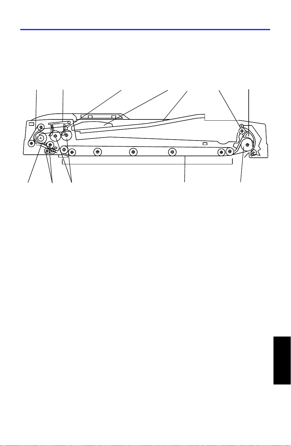
2.1 MECHANICAL COMPONENT LAYOUT
12
1. Friction Belt
2. Original Stopper
11
10
3
4
7. Inverter Pawl
8. Inverter Roller
5
9
6
72
8
3. Press Roller
4. Side Fence
5. Original Table
6. Exit Roller
9. Transport Belt
10. Pick-up Rollers
11. Pull-out Roller
12. Feed Roller
3
Feeder
Dual Job
Page 5

ELECTRICAL COMPONENT DESCRIPTION 23 April 1993
3. ELECTRICAL COMPONENT DESCRIPTION
Refer to the electrical compone nt layou t on the reverse side of the att ach ed
Point to Point for symbols and ind ex numbers.
Symbol Name Function Index
No.
Motors
M1 Feed-in Drives the feed-in system
(pick-up, feed, pull-out rollers,
separation belts)
M2 Belt Drive Drives the transport belt. 2
M3 Feed-out Drives the feed-out and the
inverter system.
Sensors
S1 DF Position Informs the CPU when the DJF
is being closed so that original
size detection sensors can
check the original size.
S2 Feed-out Checks for original misfeeds and
sets original stop timing when in
auto-reverse mode.
S3 Registration–2 Detects the leading edge of the
original to turn off the feed-in
clutch and to change the feed-in,
belt drive motors speed. Also
detects the original length.
1
5
7
8
10
S4 Original Width–3 Detects the original width. 11
S5 Original Width–1 Detects the original width. 12
S6 Original Width–2 Detects the original width. 13
S7 Registration–1 Detects the trailing edge of the
original to change the belt-drive
motor speed. Also, detects the
original length and original jam.
S8 Original Feed Detects if the originals reach the
feed roller or not.
S9 Original Set Detects if the originals are set on
the feed table.
4
14
15
16
Page 6

23 April 1993 ELECTRICAL COMPONENT DESCRIPTION
Symbol Name Function Index
No.
S10 Pulse Count Counts the pulses generated by
the pulse generator disc to
determine the original length.
Solenoids
SOL1 In vert er Energizes to invert th e orig inal
when copying two sided
originals.
SOL2 St oppe r Lifts the original stopper and
lowers the press roller to feed
the set of originals to the feed
roller.
SOL3 Separation Transmits drive to the separation
belts.
PCBs
PCB1 DF Main Board Controls all DJF functions. 3
PCB2 Indicator Panel
Contains operator indicators. 21
Board
19
4
9
18
Switches
SW1 Lift Informs the CPU when the DJF
is lifted and also serves as the
jam reset switch for the DJF.
SW2 Feed Cover Detects if the fe ed cover is
closed.
Clutches
MC1 Feed-in Transmits the feed-in motor
drive to the pick-up and feed
rollers, and to the separation
belts.
6
17
20
Feeder
Dual Job
5
Page 7
BASIC OPERATION 23 April 1993
4. BASIC OPERATION
4.1 ONE-SIDED ORIGINAL FEED
[A]
[A]
[B]
[C]
[D]
When an original is set on the DJF feed table, th e lea din g edge is stopp ed by
the stopper [A], and the feele r [B] activa te s the origin al set senso r. The Insert
Original indicator light goes out an d the DJF informs the copie r’s CPU that
the originals have been set.
When the Start key is pressed, the copier’s CPU sends the feed-in signal to
the DJF. On receipt of this signal, th e sto pp er sole no id [C] activa tes to raise
the stopper to allow the originals to be fed in, and to lower the press rollers
[D] to press the originals against the pick-up rollers as sho wn.
6
Page 8
[B]
23 April 1993 BASIC OPERATION
[A]
[C]
[E]
[D]
[F]
[D]
[F]
[B]
[G]
[E]
The feed-in clutch [A] activat es when the DJF receive the feed-in signal.
200ms after the feed-in clutch act ivate, the feed-in motor feeds all originals to
the feed roller [B].
When the originals reach the fee d rolle r, th e sto pp er sole no id [C]
de-activates to lower the original sto pper [D] and to lift up the origina l press
rollers [E].
When the originals pass through (be twe en the sepa rat ion belt [F] and feed
roller), only the lowest orig ina l is sep ara te d an d fe d on to the exposure glass.
Until then, the feed-in motor rotates slowly (372mm/sec) to ensure prop er
original feeding. When the lea ding edge of the original activates regist rat ion
sensor - 2 [G], the feed-in clutch [A] turns off to reduce the mechanical load
and prevent the next original fro m f eeding. Also, the feed motor rotat es more
quickly (1250mm/sec).
Feeder
Dual Job
7
Page 9
[A]
BASIC OPERATION 23 April 1993
[C][B]
When the leading edge of the original reaches the exposure glass, the
original is transported by the tra nsport belt [A] (belt drive motor turns on 200
ms after the start key is pressed).
When the trailing edge of the orig ina l passes through registration sen sor - 1
[B], the feed-in mot o r tu rns off. When the trailing edge of the original passes
through registratio n sen sor - 2 [C], the belt drive mot or gra du ally de crea ses
its speed to stop the origin al at the proper place on the exposure glass.
200ms after the belt drive motor turns off, the feed -in mot or tu rns on until the
next original activates reg istra tion sensor - 1 [B], the next original waits until
the first original copy jobs comple te . This op era tio n red uces the original feed
in time.
When the scanner reaches the return position, the copier’s CPU sends the
feed-out and feed-in signals to the DJF CPU in order to exchange the original
for the next original.
When the DJF receives the feed -out signal, the belt drive and fe ed -ou t
motors turn on.
When the scanner reaches the return position after scanning the last original,
the copier’s CPU sends only the fe ed-out signal to feed-out the last orig inal.
If the original is smaller than A4 sideways, the origina l just copied is
transported to the rig ht sid e of the expo sure glass then waits until the next
original copying is completed . The n the previous original is delivered . This
operation also reduces the original fe ed-in time .
8
Page 10
23 April 1993 BASIC OPERATION
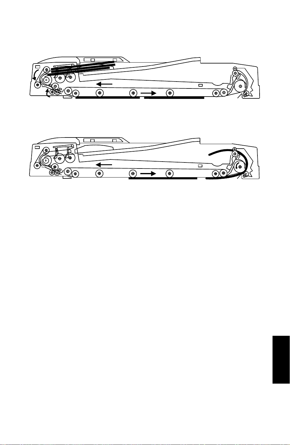
4.2 TWO-SIDED ORIGINAL FEED
[A]
[B]
Unlike one-sided original feed, the back side of the original must be copied
first to keep the originals and copies in the correct order.
During original feed-in, the sequence is the same as fo r one-side d feed ;
however, the belt drive motor con tin ue s rota ting until the original reaches the
inverter section. The DJF CPU also energize the feed-out motor and the
inverter solenoid [A] fo r a short time.
After the inverter mechanism inverts the original (10 pulses after the feed-out
sensor [B] activates), the belt drive mot or reve rses an d th e orig inal is fed
towards the original scale. It is stoppe d at the correct posit ion on the
exposure glass, and the DJF CPU sends th e cop y start signal.
When the scanner reaches the return position, the copier’s CPU sends the
invert original signal to the DJF CPU in order to ma ke a cop y of th e fro nt sid e.
The original is inverted in the same way as for back side copying.
Feeder
Dual Job
9
Page 11
BASIC OPERATION 23 April 1993
4.3 PRESET MODE
[E]
[B]
[D]
[C]
[F]
[A]
Two sets of originals for independen t cop y jobs can be set on the original tray
at the same time.
While the first set of originals [A] remains on the origin al tra y, bo th the origin al
set sensor feeler [B] and origin al fe ed senso r fee ler [C] are actuated. If the
second set of origina ls [D] ha s bee n set (st oppe d by the original stopper [E] )
and the first set of originals [A] are all fe d-in , th e orig ina l set sensor feeler [B]
is still actuated and only the original feed sensor is deactuated. There fo re,
the copier’s CPU recognizes tha t th e first jo b is comple ted.
If the second job is alrea dy pre set, the second set of originals is a ut oma tically
fed to the feed roller [F] in the same manner as the first set of origina ls was.
10
Page 12
[Fig.2]
23 April 1993 BASIC OPERATION
4.4 COMBINE 2 ORIGINALS MODE
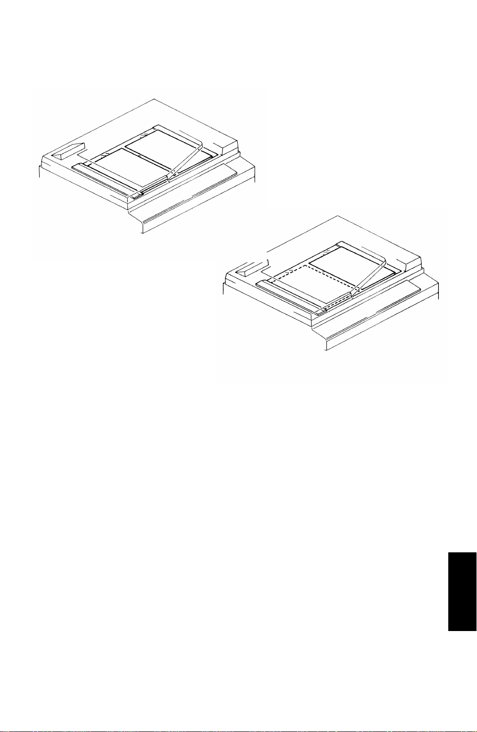
4.4.1 Overview
[Fig.1]
2 originals are fed onto the exposure glass at once in the comb ine 2 origin als
mode as shown in figure 1. This allows copying 2 originals onto one sheet of
paper automatically either in the full size mod e or in the red uction mode. If it
is used together with the dup lex mod e, 4 originals can be copied on a single
sheet of paper automatically.
If odd numbered originals are place d on the origin al ta ble, the first original is
placed on the exposure glass as sho wn in fig ure 2.
Only 1-sided originals can be used, and Auto Pa per Select (APS) and Auto
Reduce/Enlarge mod es cannot be used with this mode.
Feeder
Dual Job
11
Page 13
BASIC OPERATION 23 April 1993
4.4.2 Operation
Figure 1
Figure 2
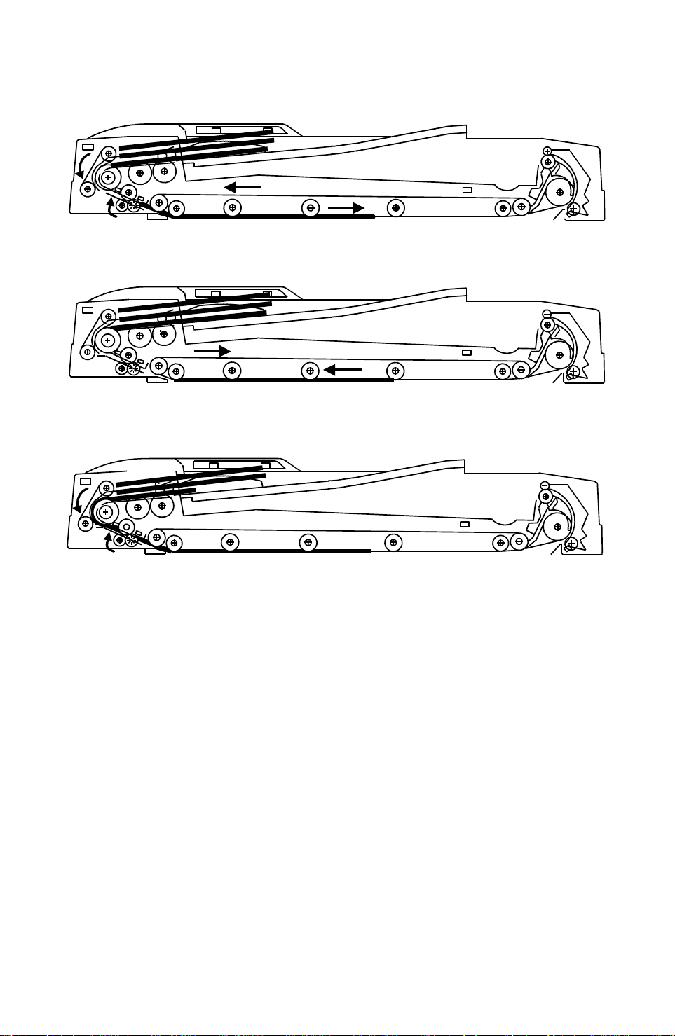
The DF operation in the combine 2 original mode is as follows:
[Figure 1]
The first original is fed in the same manner a s the one -side d orig ina l
mode. When registration sensor-2 det ect s the trailin g edge of the first
original, the feed-in and the belt drive motors sto p once and the feed -in
clutch turns on again to pre pa re for the second original fee d.
[Figure 2]
As soon as the feed-in and the belt drive motor turn off, the belt drive
motor starts rotatin g in reve rse to align the first original against the
original scale. Then the belt drive mo tor t urn s off .
[Figure 3]
50ms after the feed-in motor turns off, the feed -in mot or tu rns on again at
a lower speed (372mm/sec) to feed the secon d orig ina l.
A few pulses (0 ~ 14 pulses: depends on the SP mode adjust men t) after
the registration senso r-2 is a ctiva ted by the leading edge of th e seco nd
original, the feed-in motor and the feed-in clutch turn off.
Figure 3
12
Page 14
23 April 1993 BASIC OPERATION
Figure 4
[Figure 4]
Soon after the feed-in motor turns off, both the feed-in and the belt drive
motors turn on again at the lower speed (372mm/sec).
After registration sen sor-2 detects the trailing edge of the seco nd origin al,
the feed-in and the belt drive motors turn off and gradually th e belt drive
speed reduces to sto p the original at the pro pe r p lace on th e exposure
glass.
[Figure 5]
After the copying of th ese origin als is f inish ed , the belt drive motor and
the feed-out moto r t urn on to fee d ou t th e originals. 50mm before the
trailing edge of the first original de-activates th e feed-ou t sen sor, both the
belt drive and the feed-out motor rotate at the lower speed to improve
original stacking.
48 pulses after, the belt drive motor turns off and 60 pulses after the
feed-out sensor d et ect the trailing edge of the second original, the
feed-out motor turns off.
Figure 5
13
Feeder
Dual Job
Page 15
ORIGINAL SEPARATION 23 April 1993
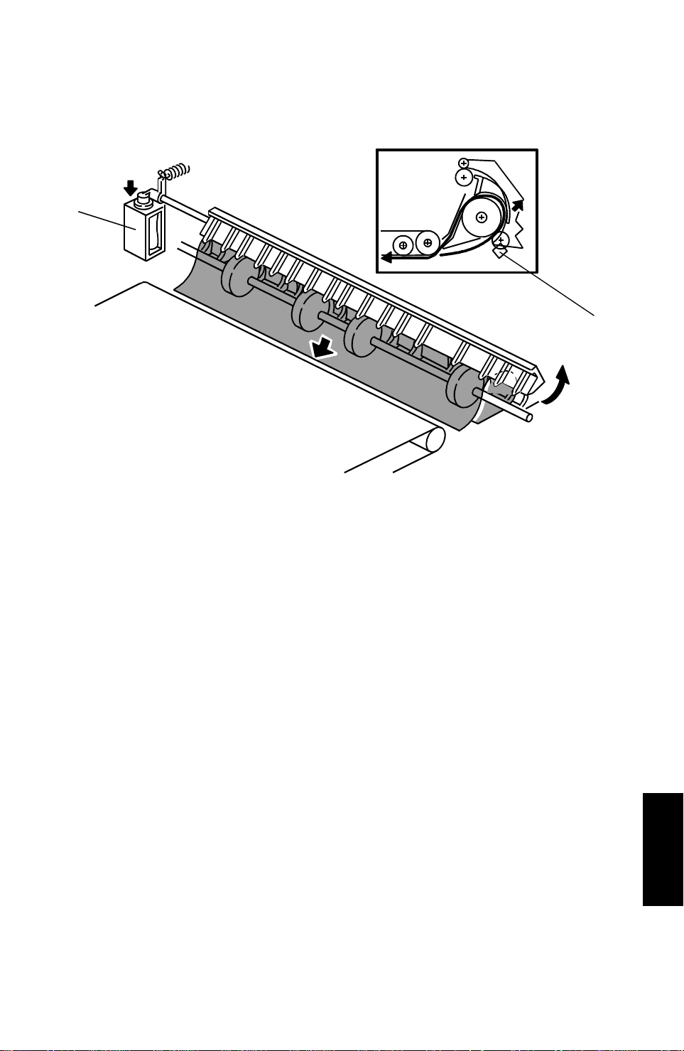
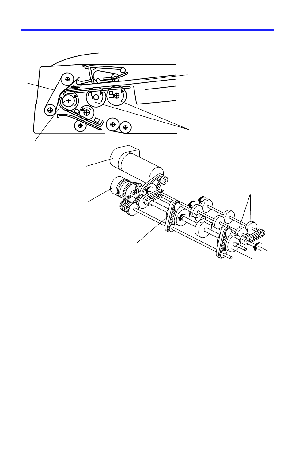
5. ORIGINAL SEPARATION
[E]
[F]
[B]
[C]
[A]
[B]
[D]
[E]
[C]
The drive from the feed-in motor [A] is transmitt ed to the pick-u p rollers [ B]
and the feed roller [C] through the feed-in clutch [D] as shown. The feed roller
and the friction belts [E] are used to feed -in and sep ara te the origin als [F] .
Only the bottom original is fed because the friction belt prevents any other
original from feeding.
Original feed starts when the feed roller starts turning and advances the
bottom original of the stack. The feed roller moves the original past the
separation belt because the driving force of the feed roller is greater than the
resistance of the friction belt . The friction belt prevents multiple fee ds
because the resistance of the frict ion belt is great er th an the frictio n be twe en
original sheets.
14
Page 16

[B]
[C]
23 April 1993 SEPARATION BELT DRIVE MECHANISM
6. SEPARATION BELT DRIVE MECHANISM
[D]
[A]
Normally the separation belt is not driven . Whe n the cop y jo b is comple te d,
the separation solenoid [A] activates for 100ms. to transmit the drive from the
feed-in motor [B] to th e sep aration belts [C] as shown.
By this operation, the part of th e frict ion belt that contacts the feed roller [D]
or the original changes to prevent multiple feeding .
When the pasted original mode is selected, the separa tio n solenoid turns on
to drive the separation belt in the same dire ction as the feed rollers.
This disables the separa tion function to reduce the frictio n be tween the
original surface and the separation belt.
Feeder
Dual Job
15
Page 17

THIN / THICK ORIGINAL MODES 23 April 1993
7. THIN / THICK ORIGINAL MODES
This document feed er ha s two dif ferent ways of stopping orig ina ls a t th e
correct position on the exposu re gla ss. They are called the thin original mode
and the thick original mode. The mode used is dete rmined by using the
copier’s User Tool No.12.
1. Thin Original Mode
The original is stopped at the corre ct po sitio n on the expo sure glass
based on encoder pulse count. The belt drive motor stops shortly after
the original trailing edge passes registration sensor - 2. (Exact timing
depends on registration adju stme nt .)
In the pasted original mode, the DJF automatica lly se lect s this mod e.
2. Thick Original Mode
When thick original mode is selecte d, the belt drive mot or rema ins
energized to carry the original approximately 10 mm pass the left scale.
Then, the belt drive motor pauses and reverses to feed th e orig inal back
against the original scale. This forces th e orig ina l aga inst the left scale
and thus aligns the trailing edge of the original with the scale.
Thick original mode is selected at the factory.
16
Page 18

[E]
[E]
23 April 1993 ORIGINAL SIZE DETECTION
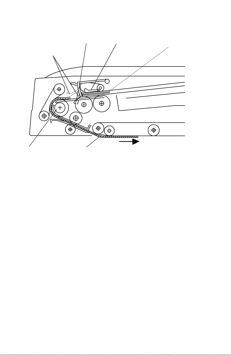
8. ORIGINAL SIZE DETECTION
[F]
The DJF detects original widt h through the on/off combination of the three
original width sensors -1 [A], -2 [B] , -3 [C] , it also detects the original length
through the use of the registration sensors -1 [D], -2 [E] and the pulse count
sensor [F].
[D]
[C]
[G]
[A]
[B]
The DJF CPU counts the pulses between regist rat ion sensor - 2 [E] on timing
and registration senso r - 1 [D] off timing.
Based on this pulse count, the CPU dete rmine the origin al len gt h.
The reason for using two registration sensors are:
1) Registration sensor -2 [E] is used to sto p the pre -fed original to wait until
the previous original is fed out. For p recise cont rol, the origin al sto p
position must be after the pull out rollers [G ]. Therefore, registration
sensor -2 is placed after the pull-out roller.
2) Registration sensor -1[D] checks the trailin g edge of the origina l. This
check is used to place the orig inal on the exposure glass.
Enough distance is required bet ween the sensor and the orig ina l scale.
Therefore, registration sensor -1 is placed 34.9 mm before sensor -2.
The original size is determine d by the combination of the det ect ed origin al
width and the length.
17
Feeder
Dual Job
Page 19

➁
➂
LIFT MECHANISM 23 April 1993
9. LIFT MECHANISM
➀
[A]
[D]
➁
➂
➀
[C]
[B]
When the DJF is opened, the lift springs [A ] pro vide enough force to ensure
that the DJF does not fall onto the expo sure glass. When the DJF is closed,
points "➀", "➁", and "➂" are aligned and no upward force is provided to the
DJF.
The lift switch [B] is actuated when the DJF is closed . The copie r t hen shif ts
to the document feeder mo de. The lift switch also serves as the reset switch
for DJF misfeeds.
When a book or thick (maximum thickness 60 mm) original is copied, the DJF
acts as a cover for the original as sh own in the figu re [C] . The lift switch is
turned off during th is co ndition, so the DJF does not function. The tension of
spring [D] returns the DJF to the norma l condition after copying a thick
original.
18
Page 20

➃
23 April 1993 ORIGINAL MISFEED DETECTION
10. ORIGINAL MISFEED DETECTION
Registration sensor -1 and the feed-o ut sensor are used for misfeed checks
to light the original misfeed ind icat or.
1. One sided original
➀
Registration
Sensor – 1
➂
➁
Feed-out Sensor
Feed-in Motor
Feed-out Motor
➄
Copying
➀: If registration sensor -1 does not activate within 150 pulses after the
feed-in motor starts turning , the CPU dete rmine s that th e origina l will not
arrive (ON check).
➁: If registration sensor -1 does not de-activate within 120 pulses, the CPU
determines that the original is still there (OFF check).
➂: If the current paper size data is 40mm lon ger o r 80mm sho rter than the
previous original size data (this ch eck is disab led in the mixed size
original mode).
➃: If the feed out sensor does no t activate within 125 pulses after the
feed-out motor starts turning , th e CPU determine s tha t the orig ina l will not
arrive (ON check).
➄: If the feed-out senso r doe s not de-activate within 60 pulses after the feed
out motor slows down, the CPU determines that the orig ina l is still there
(OFF check).
19
Feeder
Dual Job
Page 21

⑤
2nd Copying
ORIGINAL MISFEED DETECTION 23 April 1993
2. Two sided original
Registration sensor -1 and the feed-o ut sensor are used for misfeed checks
to light the original misfeed ind icat or.
Registration ON/OFF ch eck is the same as for one-sided originals.
①
②
Feed-out
Sensor
Feed-out
Motor
③
④
Forward
Belt Drive
Motor
Reverse
1st Copying
➀: If the feed-out sensor does not activate within 130 pulses after the
feed-out motor starts turning , th e CPU determine s tha t the orig ina l will not
arrive (ON check).
➁: If the feed-out sensor does not de-activate within 200 pulses, the CPU
determines that the original is still there (OFF check).
➂: If the feed-out sensor does not activate within 130 pulses after the
feed-out motor starts turning , th e CPU determine s tha t the orig ina l will not
arrive (ON check).
➃: If the feed-out sensor does not de-activate within 200 pulses, the CPU
determines that the original is still there(OFF ch eck).
➄: If the feed out sensor does no t activate within 125 pulses after the
feed-out motor starts turning , th e CPU determine s tha t the orig ina l will not
arrive (ON check).
⑥
➅: If the feed-out senso r doe s not de-activate within 60 pulses after the feed
out motor slows down, the CPU determines that the orig ina l is still there
(OFF check).
20
Page 22

11. TIMING CHART
Feed-out
11.1 DJF Timing Chart (1 sided origina l mode)
RXD
TXD
Original Set SN
Stopper SOL
Feed-in MC
Original Feed SN
Registration-1
Registration-2
Feed-Out SN
Separation SOL
Feed-in M (M1)
Feed-in
Original set
200 ms
390 ms
480 ms
200 ms
M1: 10 pls
Size
Pulse Count
Original stop
150 ms
M1: 5 pls
200 ms
Feed-out
Feed-in
No original
Size
Original
stop
M1: 5 pls
Feed-out
Feed-out
Feed amount:
M1: 3.7 mm/pls
Belt Drive M (M2)
Feed-out M (M3)
M2: 2.0 mm/pls
M3: 2.7 mm/pls
Registration-1ON
check (within 150 pls)
M3: 60 pls
Feed-out sensor OFF check (within 60 pls)
Feed-out SN ON check (within 125pls)
Incorrect Original Size check
(If more than 40 mm longer or more than 80 mm shorter than previous original).
Registration-1 OFF check (within 200 pls)
21
M3: 60 pls
Page 23

11.2 DJF TIMING CHART (COMBINE 2 ORIGINALS MODE )
Feed-out
Trailing Edge
RXD
TXD
Original Set SN
Stopper SOL
Feed-in MC
Original Feed SN
Registration-1
Registration-2
Feed-out SN
Separation SOL
Feed-in
Motor (M1)
Original set
Combine: Feed-in
390 ms
480 ms
200 ms
M1:5pls
50 ms
NOTE: 1
0 ~ 14 pls
Combine: Feed-out
Original StopSize
Feed-out
M1: 3 pls
M3: 48 pls
Belt drive
Motor (M2)
Feed-out
Motor (M3)
NOTE: Adjustable (0 ~ 14 pls) by DIP SW102
M3: 60 pls
22
Page 24

23 April 1993 INSTALLATION
12. INSTALLATION
12.1ACCESSORY CHECK
Check the accessories accord ing to the following list:
Description Q’ty
1. Installation procedure.............................................................1
2. Stepped screw........................................................................2
3. Philips screw with flat washer - M5 x 10.................... ............ .2
4. New equipment condition report
(for – 17, – 27 machines only)....................... ............ ............ .1
5. Envelope (for – 17 machine only) ................................. .. .. .....1
23
Feeder
Dual Job
Page 25

INSTALLATION 23 April 1993
12.2INSTALLATION PROCEDURE
[A]
CAUTION: When installing the Dual Job Feeder (DJ F), ma ke sure that
the copier is unplugged.
1. Remove the tape strips and the cushion.
2. If present, remove the senso r [A] from th e copier (1 screw).
NOTE: Sensor [A] is not installed on copie rs ju st out of their box.
Sensor [A] is an accessory of th e platen cover (option).
24
Page 26

[A]
23 April 1993 INSTALLATION
[B]
[B]
[C]
[E]
[D]
[B]
[B]
[F]
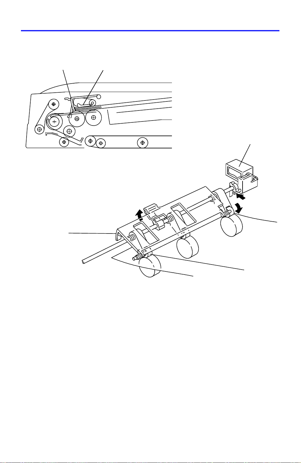
3. Install the cover [A] with the screw supplied as an accessory of th e cop ier.
4. Install two stepped screws [B] to hook the DJF.
NOTE: There is one screw hole available on the left side fo r one of th e
stepped screws. However there are two screw hole s available on
the right where the ste pp ed screw is to be inst alle d. Install the
stepped screw into the inner screw hole [C] as sho wn in th e
illustration.
5. Mount the DJF to the two stepped screws [B] by alignin g the holes in th e
DJF hinge [D] and the stepped screws, then slide the DJF to the front as
shown.
6. Secure the DJF to the copier (2 screws - M 5 x 10).
7. Remove a small cap on the upper rear cover of the copier then connect
the connector [E] an d th e fiber optic cable connector [F].
CAUTION: Locate the fiber optic cable [F] over the electrical cable[E ]
so as not to bend the fiber optic cable[F] while opening
and closing the DJF.
Feeder
Dual Job
25
Page 27

INSTALLATION 23 April 1993
[C]
[D]
[A]
[B]
[F]
[E]
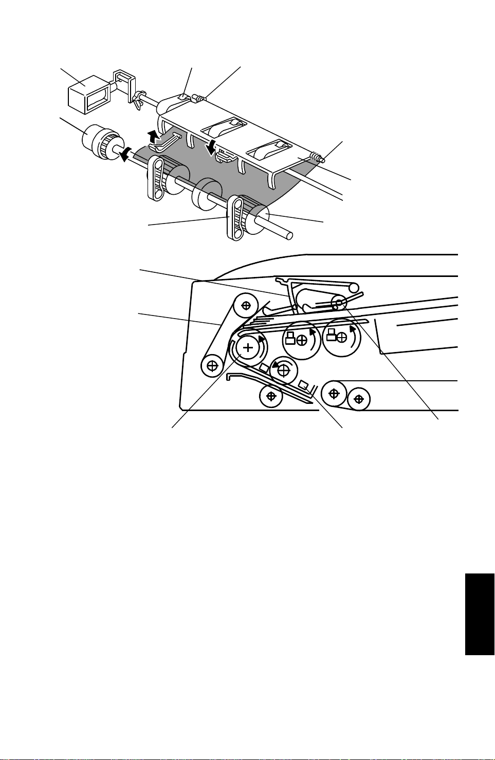
8. Adjust the height of the DJF by usin g th e ad justing dials [A]. Repeat the
following procedure for each adjustment dial.
1) Close the DJF.
2) Confirm whether or not the copier upper cover [B] and all four stoppers
[C and D] are in contact.
3) If not, loosen the lower dial [E ] (rotate counterclockwise) and adjust the
height of the DJF by rotating the upper dial [F].
NOTE: 1. First, adjust the DJF height so that the two fro nt stoppe rs [C ]
contact the upper cove r, then adjust the DJF height so tha t all
four stoppers [C and D] contact the upper cover [B].
2. Rotate the right adjusting dial clockwise to lower th e left fro nt
side of the DJF (black arrow in the illustration).
3. Rotate the left adjusting dial clockwise to lower th e righ t fro nt
side of the DJF.
4. If the height adjustment is not correct, then original skew will
occur.
26
Page 28

23 April 1993 INSTALLATION
[D]
[C]
[A]
[B]
4) Lock the adjusting (upper) dials [A] by fully rotating the lock (lower)
dials [B] clockwise.
NOTE: Mostly, height will be proper when the gap [C] is 2 mm. If the
height adjustment is not comple te d eve n if the gap [C] is smalle r
than 2 mm loosen four truss head screws [D], and tighten.
Then adjust the height again.
9. Plug in the copier and turn on the main switch.
NOTE: The copier automatically recognizes that the DJF has been
installed.
10. Make copies using the DJF a nd conf irm t he copy imag e.
27
Feeder
Dual Job
Page 29

SER VICE T ABLES 23 April 1993
13. SERVICE TABLES
13.1 DIP SWITCHES AND SWITCHE S
0: OFF 1: ON ↓ : P u sh
Modes
Motor ON
(speed Adj.)
MC, SOL
Test
Original
Feed
(Registra-
tion A dj.)
Free run
with original
Free run
Original
Distance
Adj.
(Combine
Originals)
Standard 00000 00 00 0Standard setting
DPS101 DPS102 SW
12341234101102
11011000– –Feed-in motor activates
11010100– –Belt drive motor activates
11010010– –Feed-out motor activates
0 0 1 1 1 0 0 0 0 0 St opper solenoid activat es
001101000 0Separation solenoid activates
001100100 0Feed clutch activates
001100010 0Reverse solenoid activates
01010000↓ 0 Feeds the original (thick mode)
01010001↓ 0 Feeds the original (thin mode)
01010000/10↓Delivers the original
01011000↓ 0 Fe eds t he or iginal (2 sided mode )
010110000↓
01010100↓ 0
010101000↓
10010000↓ 0 Thick / 1 sided original mode
10010001↓ 0 Thin / 1 sided original mode
10011000↓ 0 Thick / 2 sided original mode
10011001↓ 0 Thin / 2 sided original mode
10010100↓ 0 Thick / mixed size original mode
10010101↓ 0 Thin / mixed size original mode
1001001–↓ 0 Combin e 2 origin als mode
1001––––0↓Stops the free run
01100000↓ 0 Starts th e free ru n
011000000↓Stops the free run
00001000– –Shift value +3.5 mm
00000100– –Shift value +7.0 mm
00001100– –Shift value +10.5 mm
00000010– –Shift value +14.0 mm
00001001– –Shift value –3.5 mm
00000101– –Shift value –7.5 mm
00001101– –Shift value –10.5 mm
00000011– –Shift value –14.0 mm
R everses the original / Exits the
original
Feeds the original (pasted
origi nal mode)
Exits the original (paste d original
mode)
Function
28
Page 30

23 April 1993 SERVICE TABLES
13.2 VARIABLE RESISTORS
VR NO. FUNCTION
101 Adjusts the registration in 1 sided original mode
102 Adjusts the registration in 2 sided original mode
103 Adjusts feed-in motor speed
104 Adjusts belt drive motor speed
105 Adjusts feed-out motor speed
13.3 LEDs
LED NO. FUNCTION
101 Monitors the motor speed (too fast)
102 Monitors the motor speed (normal)
103 Monitors the motor speed (too slow)
13.4 FUSEs
FUSE NO. FUNCTION
101 Protects the 5 V line
102 Protects the 12 V line
103 Protects the 24 V line from feed-in motor failure
104 Protects the 24 V line from belt drive motor failure
105 Protects the 24 V line from feed-out motor failure
29
Dual Job Feeder
Page 31

R EPLAC EMENTS AND AD JUSTME NTS 23 April 1993
14. REPLACEMENTS AND ADJUSTMENTS
14.1 TRANSPORT BELT REPLACEMENT
[B]
[A]
[C]
[D]
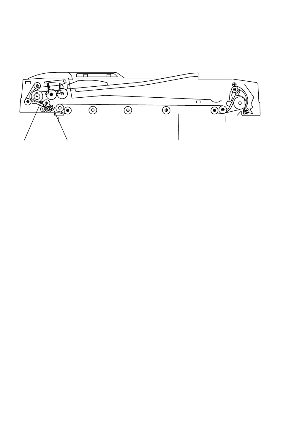
1. Turn off the copier’ s main switch.
2. Fully raise the DJF, then remove the front cover [A] (loosen 4 screws).
3. Remo ve the four screws fixing the transport belt guide assembly [B].
4. Fold the stay [C] as shown.
5. Remove the transport belt [D].
30
Page 32

23 April 1993 REPLACEMENTS AND ADJUSTMENTS
[A]
[B]
[D]
6. Install the new belt to the belt guide assembly [A].
[C]
NOTE: When setting the new belt, set the belt between the belt
guides [B].
7. While opening the original guide [C], install the belt guide assembly to the
DJF (4 screws).
8. Install the front cover [D].
9. Confirm the DJF height. (Refer to step 9 of the installation procedure.)
31
Dual Job Feeder
Page 33

[A]
R EPLAC EMENTS AND AD JUSTME NTS 23 April 1993
14.2 FEED ROLLER REPLA CEMENT
M4 x 8
M4 x 6
[D]
[E]
[F]
[C]
[B]
[H]
[G]
1. Turn off the main switch then open the feed cover [A].
2. Remove the stopper screw [B] then open the original stopper [C].
3. Remove the original table [D] (5 screws).
[H]
[G]
NOTE: When installing the original table, be sure to set t he ho ok [E] in
the hole [F].
4. Befo re removing the original guide [G], measure and remember th e
distance between the original guide and th e rear frame [H] as s hown.
This is to keep the same original side-to-side registration after the
re-installation.
32
Page 34

23 April 1993 REPLACEMENTS AND ADJUSTMENTS
[A]
[C]
[B]
[D]
[D]
[D]
[GOOD]
[NO GOOD]
5. Remove the original guide [A] (3 screws).
6. Slide the feed roller assembly [B] to the front, then remove it as shown.
7. Remove the five snap rings [C], then remove the feed rollers.
8. Install the new feed rollers, then re-assemble the machine.
NOTE: 1. When working around the feed rollers, be careful not to
damage the guide mylars [D], and set the guide mylars
correctly as shown.
2. When installing th e feed roller, be sure that the one way
bearing (silver color) is loc ated in the front side (the roller must
rotate only counter-clockwise when the shaft is fixed).
3. Do not touch the roller surface with oily hands.
4. After this replacement, adjust the side-to-side original
registration if necessary.
Dual Job Feeder
33
Page 35

R EPLAC EMENTS AND AD JUSTME NTS 23 April 1993
14.3 SEPARATION BELT REPLACEMENT
[C]
[B]
[A]
[E]
[D]
1. Turn off the main switch.
2. Fully raise the DJF, then remove the front cover [A] (loosen 4 screws).
3. Remove the screw [B], then remove the feed cover [C].
4. Remove the bracket [D] (1 screw).
5. Remove the four snap rings [E].
34
Page 36

23 April 1993 REPLACEMENTS AND ADJUSTMENTS
[A]
[C]
[D]
[B]
6. Slide the separation belt assembly [A] to the front and remove them.
7. Remove the bushings [B].
8. Remove the pulley [C].
9. Replace the separation b elts [D].
NOTE: Do not touch the separation belt with oily hands.
Dual Job Feeder
35
Page 37

R EPLAC EMENTS AND AD JUSTME NTS 23 April 1993
14.4 FEED-OUT MOTOR (FEED-OUT UNIT) REMOVAL
[B]
[C] [D]
[A]
[B]
[E]
[F]
[E]
[E]
1. Fully raise the DJF then remove the front cover. (Refer to Transport Belt
Replacement.)
2. Remove the right cover [A] (4 screws).
3. Remo ve the two screws [B] fixing the transport belt assembly, then fold
the transport belt stay [C] as shown.
4. Open the original guide [D].
5. Disconnect the four connectors [E].
6. Remove the five screws [ F].
[F]
36
Page 38

[F]
[B]
23 April 1993 REPLACEMENTS AND ADJUSTMENTS
[A]
[G]
[C]
[D]
[H]
[E]
7. Remo ve the feed-out unit [A] as shown.
8. Remove the spring [B].
9. Remove the bracket [C] with the feed-out motor from the feed-out unit (3
screws).
NOTE: When re-installing the bracket, be sure t o set the arm [D] on the
plunger pin [E].
10. Remove the pulley [F] (1 Allen screw [G]).
11. Remove the feed-in motor (4 screws) [H].
Dual Job Feeder
37
Page 39

[D]
[E]
R EPLAC EMENTS AND AD JUSTME NTS 23 April 1993
14.5 INVERTER SOLENOID REMOVAL AND ADJUSTMENT
[B]
OFF
[C]
[A]
ON
OFF
1. Remove the feed-out unit. (Refer to Feed-out Motor Removal.)
2. Remove the inverter solenoid [A] (2 screws).
NOTE: When installing the inverter solenoid, confirm the following:
ON
1) The arm [B] must b e set on the plunger pin [C].
2) Manually pull th e inverter solenoid plunger and confirm that
when the inverter solenoid d oes not activate (OFF), the
inverter guide [D] is insid e the outer inverter guide [E] and
when the inverter s olenoid activates (ON), the inver ter guide
is outside the outer inverter guide, as shown.
38
Page 40

23 April 1993 REPLACEMENTS AND ADJUSTMENTS
14.6 BELT DRIVE MOTOR REPLACEMENT
[A]
[B]
[C]
[D]
1. Remove the DJF from the copier (2 screws, 2 connectors, 2 hooks) and
place it on a stable place.
CAUTION: Before disconnecting the connectors, turn off the main
switch of the copier.
2. Remove the motor cover [A] (4 screws).
3. Remove the DF main control board cover [B] (4 screws).
4. Remove the transport belt. (Refer to the The Transport Belt Replacement.)
5. Remove the right cover [C] (4 screws).
6. Remove the belt guide assembly [ D] (6 screws).
NOTE: After re-installing the belt guide ass embly , confirm the DJF height
(Refer to the procedure 9 of the Installation Procedure.)
39
Dual Job Feeder
Page 41

R EPLAC EMENTS AND AD JUSTME NTS 23 April 1993
[A]
[D]
[C]
[B]
[F]
[E]
7. Remove the left hinge stay [A] ( 4 screws, 3 connectors).
NOTE: When re-installing the hinge stay, be sure not to pinch the
harness.
8. Remove the two connectors [B].
9. Remove the two screws [C] fixing the belt drive motor br acket.
10. While unhooking the pin [D] from the hole on the feed-in motor bracket,
remove the bracket [E] with the belt drive motor [F].
11. Remove the drive pulley (1 Allen screw) then replace the belt drive mo tor
(4 screws).
40
Page 42

23 April 1993 REPLACEMENTS AND ADJUSTMENTS
[C]
[B]
[D]
[A]
12. Re-assemble the machine.
NOTE: 1) Before installing the belt guide assembly [A] to the DJF, set
the timing belt [B] on the drive pulley [C] .
2) Make sure that the timing belt does not touch any harness.
3) Do not bend the anti-static brush [D].
41
Dual Job Feeder
Page 43

R EPLAC EMENTS AND AD JUSTME NTS 23 April 1993
14.7 FEED-IN CLUTCH (FEED-IN UNIT) RE MOVAL
[B]
[A]
[D]
[C]
1. Remove the following parts:
1) Original table [A] (refer to Feed Roller Replacement),
2) Feed cover [B] (refer to Separation Belt Replacement),
3) Left h inge stay [C] (refer to Belt Drive Motor Replacement).
2. Remove the table bracket [D] (2 screws).
42
Page 44

23 April 1993 REPLACEMENTS AND ADJUSTMENTS
[B]
[A]
[D]
[E]
[D]
[C]
[E]
3. Disconnect the connectors [ A].
4. Remove the feed-in unit [B] (4 screws).
5. Replace the feed-in clutch [C] (1 Allen screw).
NOTE: When installing the clutch on the shaft [D], align the sur fa ce of
the clutch stopper [E] and the head of the shaft [D], as shown.
Dual Job Feeder
43
Page 45

R EPLAC EMENTS AND AD JUSTME NTS 23 April 1993
14.8 STOPPER SOLENOID REPLACEMENT
[C]
[D]
[B]
[A]
[C]
[D]
1. Remove the feed-in unit. (Refer to Feed-in Clutch Replacement)
2. Remo ve the bracket [A] with the stopper solenoid (2 screws).
3. Replace the stopper solenoid [B] (2 screws).
NOTE: When installing the stopper solenoid, pay atten tion to the
following points:
1) The spring [C] must be correctly hooked to the stopper [D],
as shown.
2) Manually pull the stopper solenoid plunger to confirm that the
press rollers firmly contacts the pick-up rollers. When the
pick-up r ollers are manually rotated, the press rollers also
rotate. If not, adjust the stopper solenoid position.
44
Page 46

0 ~ 2 mm
23 April 1993 REPLACEMENTS AND ADJUSTMENTS
14.9 VERTICAL REGISTRATION ADJUSTMENT
14.9.1 One Sided Original Mode
[C]
[A]
[B]
1. Remove the small cover at the rear sid e on the upper DJF cover.
2. Turn on DIP-SW No. 101-2, 4 and 102-4.
3. Set a sheet of A4 / 8 1/2" x 11" (53 ~ 80 g/m2 / 14 ~ 22 lb)sideways
paper on the original table.
4. Push SW 101 [A].
5. After the original stop on the exposure glass, gently raise the DJF so that
the original d oes n ot move.
6. Confirm that the ga p be tween the trailing edge of the paper and the
original left scale [B] is within 2 mm.
7. It the gap is larger than 2 mm, adjust the registration by using the copier
SP mode ( SP Adjustment - PAGE 6).
1
NOTE: 1. Before setting the original on the original table again, open and
close the feed unit cover [C].
2. After completing the adjustment, return the DIP switches to the
origin al condition.
Dual Job Feeder
45
Page 47

R EPLAC EMENTS AND AD JUSTME NTS 23 April 1993
14.9.2 Two Sided Original Mode
[A]
[C]
[B]
10 ± 2 mm
1. Remove the copier’s left scale [A] (2 screws).
2. Remove the small cover at the rear sid e on the upper DJF cover then turn
on DIP SW 101-2, 101-4 and 102-1.
3. Set a sheet of A4 / 8 1/2" x 11" (53 ~ 80 g/m2 / 14 ~ 22 lb) sideways
paper on the original table.
4. Push SW 101 [B].
5. After the original stops on the exposure glass, gently raise the DJF so
that the original does not move.
6. Confirm that the gap between the trailin g edge of the paper and the left
edge [C] of the original rear scale is 10 ± 2 mm.
7. It the gap is not within specification, adjust the registration by using the
copier SP mode ( SP Adjustment - PAGE 6).
1
NOTE: 1. Before setting the original on the original table again, open and
close the feed unit cover [C].
2. After completing the adjustment, return the DIP switches to
their original condit ion.
46
Page 48

23 April 1993 REPLACEMENTS AND ADJUSTMENTS
14.9.3 Combine 2 Originals Mode
1. Make a copy in combine 2 originals mode.
2. Adjust the gap between the first original and the second original. It should
be as small as possible. (Do this by changing the DIP SW 102
combination, 3.5mm/step, as shown in the t able)
NOTE: Factory settings are all "0" (OFF).
If DIP SW 102-4 is "0" (OFF), the distance between the 1st and
2nd copies is wider (+ ).
102-4 102-3 102-2 102-1 Shift value
00000
0001+ 3.5 mm
0010+ 7.0 mm
0011+10.5 mm
0100+14.0 mm
1001- 3.5 mm
1010- 7.0 mm
1011-10.5 mm
1100-14.0 mm
47
Dual Job Feeder
Page 49

R EPLAC EMENTS AND AD JUSTME NTS 23 April 1993
14.10 SIDE TO SIDE REGISTRATION ADJUSTMENT
[D]
[A]
[C]
5 ± 2 mm
1. Remove the small cover at the rear sid e on the upper DJF cover.
2. Turn on DIP SW 101-2 and 101-4.
3. Set a sheet of A4 / 8 1/2" x 11" (53 ~ 80 g/m2 / 14 ~ 22 lb) sideways
paper on the original table.
4. Push SW 101 [A].
[B]
5. After the original stops on the exposure glass, gently raise the DJF so
that the original does not move.
6. Confirm if the gap between the rear edge of the paper and the original
rear scale is 5 ± 2 mm.
7. If the gap is not within the specification, adjust the registration by using
copier’s SP mode ( SP Adjustment - PAGE 4).
1
8. It the gap is not within specification by using SP mode, loosen the eight
sc rews fixing the original table [B] and the original guide [C] and shift the
original table and the original guide position accordingly.
NOTE: Before setting the original on the original table again, open and
close the feed unit cover [D].
48
Page 50

VR104
VR105
VR101
DPS102
23 April 1993 REPLACEMENTS AND ADJUSTMENTS
14.11 MOTOR S PEE D ADJUSTMENT
DPS101
VR103
VR102
[A]
[B]
[C]
LED101
LED102
LED103
SW101
SW102
1. Close the DJF and r e move the small cover at the rear side on the upper
DJF cover.
2. Turn on DIP-SW No. 101-1, -2 and -4.
3. Turn on the appropriate DIP switch corresponding to the adjusting motor
to be adjusted (see the table below).
4. Rotate the appropriate VR (see the table below) so that LED102 (green )
[A] lights.
NOTE: If the motor rotat ion speed is too high, LED101 (red) [B] lights
and if too slow, LED 103 (red) [C] lights.
5. Return the DIP switches to their original condition.
Motor DIP SW VR
Feed-in 102-1 103
Belt drive 102-2 104
Feed-o ut 102-3 105
Dual Job Feeder
49
 Loading...