

Page 1

FT6645/6655/6665
SERVICE TRAINING
MANUAL
Page 2

SECTION 1
OVERALL MACHINE
INFORMATION
Page 3

1. SPECIFICATION
Configuration: Console
Copy Process: Dry electrostatic transf er system
Toner Supply Control: Fuzzy Control
Photoconductor: OPC drum
Originals: Sheet/Book
Original Size: Maximum A3/11" x 17"
Original Alignment: Left rear corner
Copy Paper Size: Maximum A3/11" x 17"
Minimum A5/51/2" x 81/2" (Tray)
B5/81/2" x 11" (1.5K LCT)
A6/51/2" x 81/2" (By-pass)
Duplex Copying: Maximum A3/11" x 17"
Minimum A5/51/2" x 81/2" (sideways)
Copy Paper Weight: Paper tray: 52 ~ 128 g/m2, 14 ~ 34 lb
Bypass feed table: 52 ~ 157 g/m2, 14 ~ 42 lb
Duplex copying: 64 ~ 104 g/m2, 17 ~ 24 lb
Reproduction Ratios: 4 Enlargement and 6 Reduction
A4/A3 Version LT/LDG Version
Enlargement 200%
141%
122%
115%
Full Size 100% 100%
Reduction 93%
82%
75%
71%
65%
50%
200%
155%
129%
121%
93%
85%
77%
74%
65%
50%
STM 1-1 FT6645/6655/6665
Page 4

Rev. 7/94
Power Source: 115V, 60Hz, more than 20A (for N.A)
220 ∼ 240V, 50Hz/60Hz, more than 10A ( for EU
and AA)
Power Consumptio n: FT6645(A095) and FT 6655 (A096) copiers
Copier only Full system*
Warm-up 0.90 kVA 0.90 kVA
Stand-by 0.25 kVA 0.25 kVA
Copying 1.20 kVA 1.30 kVA
Maximum 1.45 kVA 1.50 kVA
FT6665 (A097) copier
Copier only Full system*
120 V
machine
Warm-up 1.20 kVA 1.20 kVA 1.25 kVA 1.25 kVA
Stand-by 0.25 kVA 0.22 kVA 0.25 kVA 0.24 kVA
Copying 1.80 kVA 1.70 kVA 1.80 kVA 1.75 kVA
Maximum 1.80 kVA 1.70 kVA 1.80 kVA 1.75 kVA
230 V
machine
120 V
machine
230 V
machine
*Full System:
• Mainframe with dual job feeder, compact
sorter stapler and 3,50 0-sheet large capacity
tray
• Mainframe with dual job feeder, floor type
sorter stapler and 3,50 0-sheet large capacity
tray
• Mainfra me with recir culatin g document
handler, finisher and 3,500-sheet large
capacity tray
FT6645/6655/6665 1-2 STM
Page 5

Noise Emission:
Rev. 7/94
Sound Pressure Leve l:
The meas ure ments are
made according to
ISO7779
Copying (FT6645/6655 copiers) 55 dB (A) 62 dB (A)
Copying (FT6665 copier) 60 dB (A) 64 dB (A)
Copier only Full system*
Full System:
• Mainframe with dual job feeder, compact
sorter stapler and 3,50 0-sheet large capacity
tray
• Mainframe with dual job feeder, floor type
sorter stapler and 3,50 0-sheet large capacity
tray
• Mainfra me with recir culatin g document
handler, finisher and 3,500-sheet large
capacity tray
Dimensions: 690 x 690 x 980 (W x D x H Mainframe only)
1280 x 690 x 1020 (W x D x H Mainframe with
copy tray, platen cover)
Weight: Copier only: (Without the optional platen cover
= Approximately 2 kg)
FT6645 (A095) copier: Approximately (333 lbs)
FT6655 (A096) copier: Approximately (360 lbs)
FT6665 (A097) copier: Approximately (360 lbs)
Zoom: From 50% to 200% in 1% steps
Copying Speed:
A4/LT (sideways) A3/DLT B4/LG
FT6645 copier 45 23 27
FT6655 copier 55 28 35
FT6665 copier 65 33 41
Warm-up Time: Less than 5 minutes (20°C)
First Copy Time:
(A4/81/2" x 11" sideways
3.1 seconds FT6645/6 655 (A095 /A096 copier s)
2.7 seconds FT6665 (A097 copier)
from the 1st feed station)
Copy Number Input: Number keys, 1 to 999 (count up or count down)
Manual Image Density 7 steps
Selection:
STM 1-3 FT6645/6655/6665
Page 6

Rev. 7/94
Automatic Reset: 1 minute standard setting; can also be set from 1
second to 999 seconds or no auto reset.
Copy Paper Capacity: • By-pass feed table: approximately 50 sheets
• Paper tray: approximately 550 sheets
• Tandem tray: approximately 500 sheets/side,
1000 total
• Large capacity tray: approximately 1,500
sheets
• Duplex: 50 sheets
Toner Replenishment: Black Only: Cartridge exchan ge
1,100 g/cartridge, Yield 38,000 copies
(6% originals)
Developer
Replenishment:
Black Only: 1Kg/Bag, 120,000 copies
(6% originals)
Optional Equipment: • Type 610, Platen cover
• DF60, Dual job feeder
• DH400, Recirculating document handler
• ST25, 20 bin sorter stapler (Floor type)
• ST24, 20 bin compact sorter stapler
• SR400, Finisher
• RT31, 3,500-sheet Large capacity tray
• Type B, Receiving Tray
Toner Collection
7,500cc, 120,000 copies (6% origin als)
Bottle Capacity:
FT6645/6655/6665 1-4 STM
Page 7
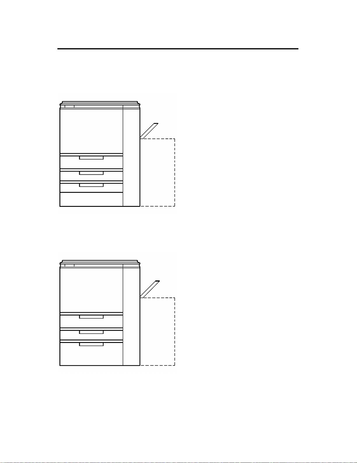
2. MACHINE CONFIGURATION
2.1 COPIER OVERVIEW
There are two types of mainframe.
FT6645 (A095) copier
50
Rev. 7/94
550
550
550
FT6655 (A096) FT6665 (A097) copiers
500 x 2 or 500
550
1,500
(3,500)
50
(3,500)
Three 550-shee t paper trays Optiona l
3,500-sheet larg e capacity t ray
Tandem pape r tray
(including two 500-sheet paper tray)
One 550-sheet paper tray
1,500-sheet built-in large capacity tray
Optional 3,500-sheet large capacity tray
STM 1-5 FT6645/6655/6665
Page 8
Rev. 7/94
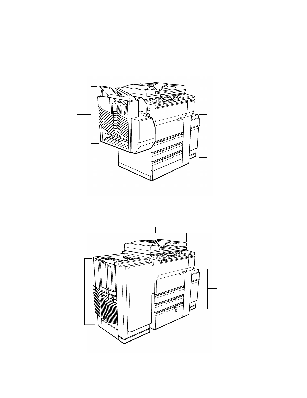
2.2 SYSTEM OVERVIEW
System A
The mainframe FT6645 (A095) with dual job feeder and compact sorter
stapler.
Compact
sorter stapler
ST24 (A374)
Dual job feeder DF60 (A376)
3,500-sheet s
large capacity
tray
RT31 (A38 0)
System B
Mainframe type FT6645/6655/66 65( A0 95/A09 6/A097) with dual job feeder
and floor type sorter stapler. The mainframe in the illustration below is the
FT6655 (A096).
Floor type
sorter stapler
ST25 (A377)
Dual job feeder DF60 (A376)
3,500-sheets
large capacity tray
RT31(A380)
FT6645/6655/6665 1-6 STM
Page 9
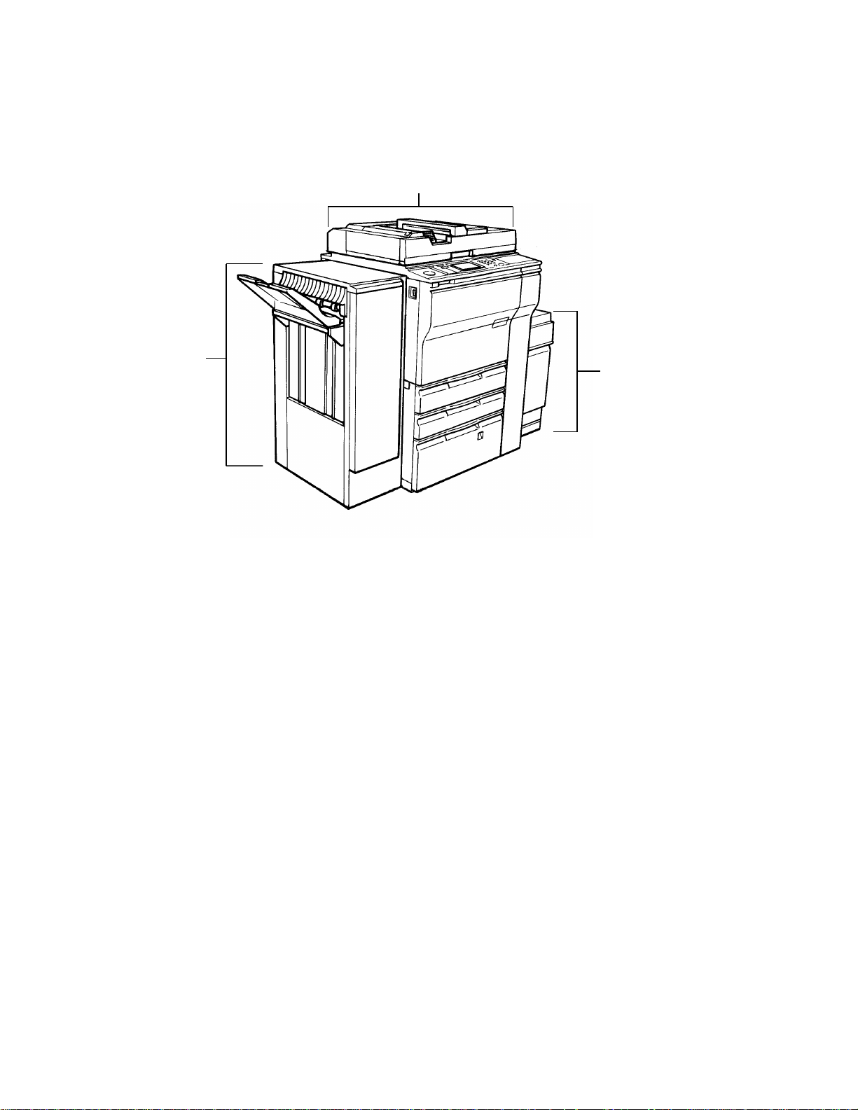
System C
The mainframe FT6665/6665 (A096/A097) with recirculating document
handler and finisher.
Recirculating document handler DH400 (A378)
Finisher
SR400 (A379)
Rev. 10/94
3,500-sheets
large capacity tray
RT31 (A38 0)
NOTE: All references to (A096 copier only) now refers to (A096 and
A097 copiers).
STM 1-7 FT6645/6655/6665
Page 10
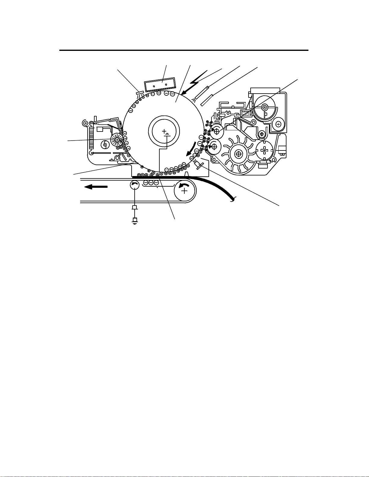
3. COPY PROCESS AROUND THE DRUM
5
4
10
11
12
9
8
3
6
7
1. OPC DRUM
The organic photo conductive (OPC) drum (100 mm diameter) has high
resistance in the dark and low resistance under light.
2. DRUM CHARGE
In the dark, the charge corona unit gives a uniform negative charge to the
OPC drum. The charge remains on the surface of the drum. The amount of
negative charge on the drum is propor tional to the negative grid bias voltage
applied to the grid plate on the charge corona unit.
3. EXPOSURE
An image of the original is reflected to the OPC drum surface via the optics
section. The charge on the drum surface is dissipated in direct proportion to
the intensity of the reflected light, thus prod ucing an electr ical lat ent imag e on
the drum surface.
The amount of charge remaining as a latent image on the drum depends on
the exposure lamp intensity contr olled by the exposure lamp voltage.
4. ERASE
The erase lamp illuminates the areas of the charged drum surface that will
not be used for the copy image. The resistance of drum in the illuminated
areas drops and the charge on those area s dissipa tes.
FT6645/6655/6665 1-8 STM
Page 11

5. DRUM POTENTIAL SENSOR
The drum potential sensor detects the electr ical poten tial o n the drum to
compensate image pro cessing elements.
6. DEVELOPMENT
Positively charged toner is attracted to the negatively charged areas of the
drum, thus developing the laten t image. (The positive triboele ctric char ge of
the toner is caused by friction between the carrier and toner particles.)
The development bias voltage applied to the development roller shafts
controls two things:
1) The "breakaway" level at which toner is attracted to the drum and at
which toner remains on the developm ent rollers.
2) The amount of toner to be attracted to the drum.
The higher the negative development bias voltage is, the less toner is
attracted to the drum surface.
7. PRE-TRANSFER LAMP (PTL)
The PTL illuminates the drum to remove almost all the negative charge fro m
the exposed areas of the drum. This makes imag e transf er easier .
8. IMAGE TRANSFER
Paper is fed to the drum surface at the proper timing so as to align the copy
paper and the developed image on the drum surface. Then, a negative
charge is applied to the reverse side of the copy paper by the transfer belt,
producing an electrical force which pulls the toner particle s from the dru m
surface onto the copy paper. At the same time, the copy paper is electrica lly
attracted to the transfer belt.
9. PAPER SEPARATION
Paper separates from the OPC drum by the electrical attraction between the
paper and the transfer belt. The pick-off pawls help to separate the paper
from the drum.
10. CLEANING
The cleaning brush removes toner remaining on the drum after image
transfer and the cleaning blade scrapes off all the remaining toner.
11. QUENCHING
Light from the quenching lamp electrically neut ralizes the charge potential of
the drum surface.
STM 1-9 FT6645/6655/6665
Page 12
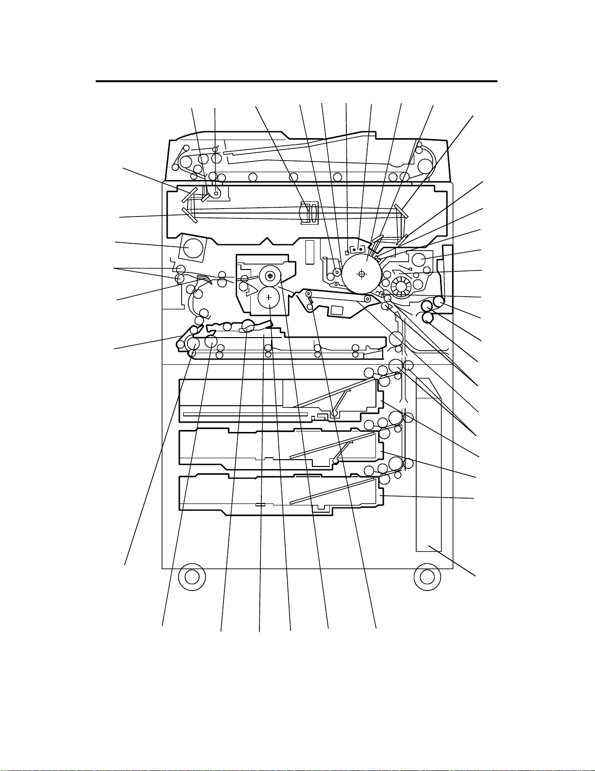
4. MECHANICAL COMPONENT LAYOUT
11
10
29
39
38
37
36
7
3
4
2
1
5
6
9
8
12
13
14
15
16
17
18
19
20
21
35
34
33
32
31
22
23
24
25
26
27
28
30
FT6645/6655/6665 1-10 STM
Page 13

1. 3rd Mirror
2. 2nd Mirror
3. 1st Mirror
4. Exposure Lamp
5. Lens
6. Cleaning Brush
7. Cleaning Blade
8. Quenching Lamp
9. Charge Corona Unit
10. OPC Drum
11. 6th Mirror
12. 4th Mirror
13. 5th Mirror
21. Separation Roller, Bypass
22. Registration Rollers
23. Transfer Belt
24. Vertical Transport Roller s
25. Tandem Tray (A096 copier)
550-sheet Tray (A095 copier)
26. Universal Tray
27. 1500-sheet LCT (A096 copier)
550-sheet Tray (A095 copier)
28. Toner Collection Bottle
29. Transfer Belt Cleaning Blade
30. Hot Roller
31. Pressure Roller
32. Jogger Fences
14. Erase Unit
15. Drum Potential Sensor
16. Toner Hopper
17. Development Unit
18. Pre-Transfer Lamp
19. Pick-up Roller, Bypass
20. Feed Roller, Bypass
33. Duplex Positioning Roller
34. Duplex Pick-up Roller
35. Duplex Feed Roller
36. Separation Belt
37. Junction Gate
38. Exit Rollers
39. Optics Cooling Fan
STM 1-11 FT6645/6655/6665
Page 14
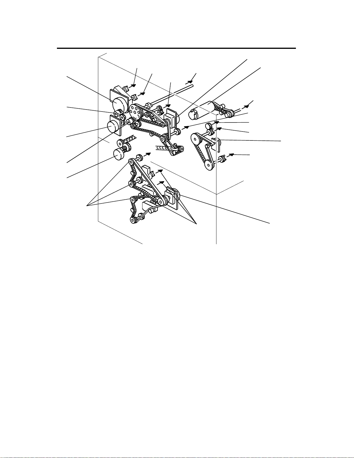
5. DRIVE LAYOUT
2
3
4
5
6
❶
❽
❼
❻
❺
❾
9
10
11
1
❷
❸
8
7
❹
❶ Main Motor
❷ Scanner Drive Motor
❸ Fusing/Duplex Drive Motor
❹ Paper Feed Motor
❺ Toner Collection Motor
❻ Registration Clutch
❼ By-Pass Feed Motor
❽ BY-Pass Feed Clutch
❾ Development Drive Motor
1. OPC Drum
2. Scanner Unit
3. Transfer Belt Unit
4. Paper Exit Unit
5. Fusing Unit
6. Duplex Unit
7. Paper Trays
8. Paper Feed Units
9. Toner Hopper
10. Development Unit
11. Cleaning Unit
FT6645/6655/6665 1-12 STM
Page 15
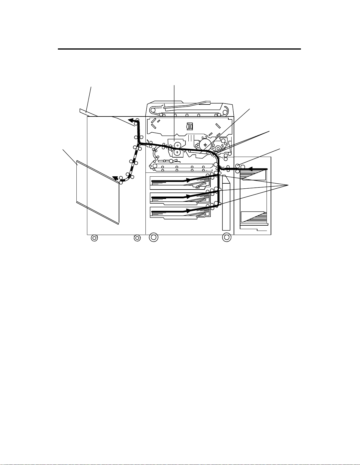
6. PAPER PATH
6.1 STANDARD COPYING
[E]
[F]
[D]
[C]
[B]
[A]
[A]
Paper feed begins from the exterior LCT, by-pass feed table or paper feed
stations in the paper tray unit. The copy paper then follows one of two paths
inside the copier. The path followed depen ds on which mode the opera tor
has selected. For copy processing, all sheets follow the same path s from the
paper feed mechanism [A] thro ugh the reg istra tion rollers [B], transfer belt
[C], and fusing unit [D]. After that, copies are delivered to the sorter bins [E]
or proof tray [F], however , 2 sided copies are diverted for furth er processing.
STM 1-13 FT6645/6655/6665
Page 16
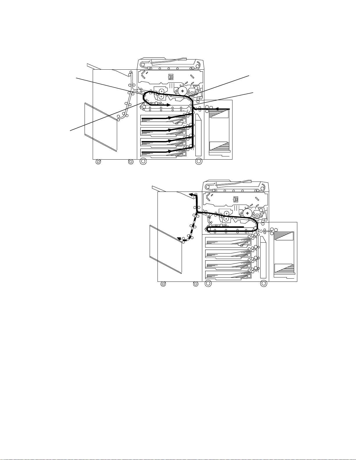
6.2 MULTIPLE 2-SIDED COPYING
a. Front Side
[B]
[A]
[D]
[C]
b. Rear Side
In this mode the junction gate [A] directs sheets exiting the fusing unit to the
duplex tray entrance. After that, all sheets follow the path through the duplex
entrance rollers [B].
After all front side copying is completed, the sheets on the duplex tray are fed
in order from the bottom to the top and follow the path throug h the duplex
feed mechanism and vertical tra nspor t rollers [C] to the registration rolle rs
[D]. After that, these sheets follow the same path as standard copying from
the registration rollers to the sorter.
FT6645/6655/6665 1-14 STM
Page 17

7. ELECTRICAL COMPONENT DESCRIPTION
Refer to the electrical component layout on the reverse side of the Point to
Point for symbols and index numbers.
NOTE: For RT31 description s, see Section 7, page 3
Symbol Name Function Index
No.
Motors
M 1 Scanner Drive Drives the 1st and 2nd scanners
(dc servo).
M 2 Exhaust Fan Rem oves the heat from around
the fusing unit.
M 3 Main Drives the main unit components. 44
M 4 Development Drive Drives the development unit. 45
M 5 By-pass Feed Drives the by-pass feed rollers. 46
M 6 3rd Scanner Drive Drives the 3rd scanner (dc
stepper)
M 7 Toner Bottle Drive Rotates the toner bottle to supply
toner to the toner hopper.
M 8 Charge Wire Cleaner
Drive
M 9 Jogger Drives the jogger fences to
M10 Lens Horizontal Drive Shifts the lens horizontal position. 51
M11 Lens Vertical Drive Shifts the lens vertica l position. 52
Drives the main charge wire
cleaner to clean the charge wire.
square the paper stack in the
duplex tray (dc stepper).
42
43
47
48
49
50
M12 Optic Cooling Fan Removes heat from the optics
unit.
M13 Fusing/Duplex Drive Drives the fusing unit, the duplex
unit, and the paper exit rollers.
M14 Paper Feed Drives all feed and transport
rollers in the paper tray unit.
M15 1st Lift Raises the bottom plate in the 1st
paper tray.
M16 2nd Lift Raises the bottom plate in the
2nd paper tray.
M17 Toner Collection Transports the collected toner to
the toner collection bottle.
STM 1-15 FT6645/6655/6665
53
54
90
91
92
93
Page 18

Rev. 7/94
Symbol Name Function Index
No.
M18 3rd Lift
(A095)
M19 Side Fence Drive
(A096/A097)
Raises the bottom plate in the 3rd
paper tray.
Opens and closes the front and
the rear side fences of the
tandem tray.
M20 Rear Fence Drive
(A096/A097)
Moves the papers stacked in the
left tandem tray to the right
tandem tray.
M21 LCT Motor
(A096/A097)
Lifts and lowers the LCT bottom
plate to bring paper to the feed
position and allow loading of the
paper.
Magnetic Clutches
MC1 Toner Supply Turns the toner supply roller to
supply toner to the development
unit.
MC2 Registration Drives the registration rollers. 58
94
95
96
127
57
MC3 By-pass Feed Starts paper feed from the
by-pass feed table.
MC4 Duplex Transport Drives the duplex transport rollers
to transport the paper to the
vertical transport rollers.
MC5 Duplex Feed Starts paper feed from the duplex
tray to the duplex transport rollers.
MC6 1st Feed Starts paper feed from the 1st
feed tray.
MC7 2nd Feed Starts paper feed from the 2nd
feed tray.
MC8 3rd Feed Starts paper feed from the 3rd
feed tray.
60
64
65
99
101
104
FT6645/6655/6665 1-16 STM
Page 19

Rev. 7/94
Symbol Name Function Index
No.
Switches
SW1 By-pass Table Detects if the by-pass feed table
25
is open or closed.
SW2 Front Door Safety Cuts the DC power line and
29
detects if the front door is open or
not.
SW3 1st Tray Set
Detects if the 1st tray is set or not. 66
(A095)
SW4 2nd Paper Size Determines what size paper is in
67
the 2nd (universal) paper tray.
SW5 Toner Overflow Detects when the toner collection
75
bottle is full.
SW6 Toner Collection
Bottle Set
SW7 Lower Front Door
Safety
SW8 3rd Tray Set
Detects if the toner collection
77
bottle is set or not.
Detects if the front door is open
83
or not.
Detects if the 3rd tray is set or not. 84
(A095)
SW9 Main Provides power to the copier 122
SW10 Tray Down
Lowers the LCT bottom plate. 126
(A096/A097)
Solenoids
SOL 1 Junction Gate Moves the junction gate to direct
copies to the duplex tray or to the
paper exit.
SOL 2 Duplex Positioning Controls the up- down move men t
of the positioning roller.
SOL 3 By-pass Pick-up Controls the up-down movemen t
of the pick-up roller for by-pass
feed.
SOL 4 Guide Plate Opens the guide plate when a
paper misfeed occurs aro und this
area.
SOL 5 Transfer Belt
Positioning
Controls the up-down move ment
of the transfer belt unit.
55
56
61
59
62
STM 1-17 FT6645/6655/6665
Page 20

Symbol Name Function Index
No.
SOL 6 Pressure Arm Presses the paper on the duplex
tray against the duplex feed
rollers.
SOL 7 Tandem Lock Locks the left tandem feed tray
and separates the right and left
tandem trays.
SOL 8 1st Pick-up Controls the up-down move ment
of the pick-up roller in the 1st
feed station.
SOL 9 1st Separation Roller Controls the up-down movement
of the separation roller in the 1st
feed station.
SOL10 2nd Pick-up Controls the up-down movement
of the pick-up roller in the 2nd
feed station.
SOL11 2nd Separation Roller Controls the up-down movemen t
of the separation roller in the 2nd
feed station.
SOL12 3rd Pick-up Controls the up-down move ment
of the pick-up roller in the 3rd
feed station.
63
97
98
100
102
103
105
SOL13 3rd Separation Roller Controls the up-down move ment
of the separation roller in the 3rd
feed station.
Sensors
S 1 Scanner HP Informs the CPU when the 1st
and 2nd scanners are at the
home position.
S 2 Platen Cover
Position–1
Informs the CPU that the platen
cover is in the up or down
position (related to APS/ARE
function).
S 3 Platen Cover
Position–2
Informs the CPU that the platen
cover is in the up or down
position to detect if the original
has been removed or not.
106
1
2
3
FT6645/6655/6665 1-18 STM
Page 21

Rev. 12/93
Symbol Name Function Index
No.
S 4 Lens Vertical HP Informs the CPU that the lens is
at the full-size position.
S 5 Lens Horizontal HP Informs the CPU that the lens is
at the horizontal home position .
S 6 3rd Scanner HP Informs the CPU when the 3rd
scanner is at the home position.
S 7 By-Pass Paper End Informs the CPU that there is no
paper in the by-pass feed table.
S 8 Guide Plate Position Informs the CPU if the
registration guide plate is closed
or not.
S 9 Jogger HP Detects if the duplex jogger
fences are at the home position
or not.
S10 Vertical Transport Detects the leading edge of the
paper to determine the paper
feed timing of the next sheet.
S11 Duplex Exit Dete cts the leading edge of the
paper to determine the duplex
transport clutch on timing .
4
5
6
7
8
9
10
11
S12 Duplex Entrance
Sensor
Detects the leading edge of the
paper to determine the duplex
14
feed clutch off timing.
S13 Duplex Paper End Detects paper in the duplex tray. 13
S14 Duplex Transport Detects the leading edge of the
12
paper to control the jogger motor
and the positioning solenoid on
timing.
S15 Exit Detects misfeeds. 15
S16 Fusing Exit Detects misfeeds. 16
S17 Paper Guide Detects misfeeds. 17
S18 Auto Image Density Senses the background density
20
of the original.
S19 Original Length–2 Detects original length. 21
S20 Original Length–1 Detects original length. 22
S21 Original Width Detects original width. 23
STM 1-19 FT6645/6655/6665
Page 22

Symbol Name Function Index
No.
S22 By-Pass Paper Size Informs the CPU what size paper
26
is in the by-pass feed table.
S23 Toner Density Senses the amount of toner in
27
the black developer.
S24 Registration Detects misfeeds and controls
28
registration clutch off-on timing.
S25 Toner End Detects toner end condition. 30
S26 Auto-Respon se Returns the display from the
34
screen saver.
S27 Drum Potential Detects the drum surface
39
potential.
S28 Image Density Detects the density of the ID
41
sensor pattern on the drum.
S29 1st Paper End Informs the CPU when the 1st
68
cassette runs out of paper.
S30 1st Paper Near End Informs the CPU when the 1st
69
cassette is in near end condition.
S31 1st Paper Feed Controls the 1st paper feed clutch
70
off/on timing and the 1st pick-up
solenoid off timing.
S32 2nd Paper Near End Informs the CPU when the 2nd
cassette is in near end condition.
S33 1st Lift Detects the correct feed height of
the 1st cassette.
S34 2nd Paper End Informs the CPU when the 2nd
cassette runs out of paper.
S35 Toner Collection
Motor
Detects the toner collection motor
operation.
S36 2nd Lift Detects the correct feed height of
the 2nd cassette.
S37 3rd Lift Detects the correct feed height of
the 3rd cassette.
S38 3rd Paper Near End
(A095 copier only)
Informs the CPU when the 3rd
cassette is in near end condition.
S39 3rd Paper End Informs the CPU when the 3rd
cassette runs out of paper.
71
72
73
74
76
78
79
80
FT6645/6655/6665 1-20 STM
Page 23

Rev. 7/94
Symbol Name Function Index
No.
S40 3rd Paper Feed Cont rols the 3rd paper feed
clutch off/on timing and the 3rd
pick-up solenoid off timing.
S41 2nd Paper Feed Controls the 2nd paper feed
clutch off/on timing and the 2nd
pick-up solenoid off timing.
S42 Base Plate Down
(A096/A097)
Detects when the bottom plate is
completely lowered to stop the
1st lift motor.
S43 Side Fence
Positioning
Informs the CPU when the
tandem tray side fences are open.
(A096/A097)
S44 Rear Fence Return
(A096/A097)
Informs the CPU when the
tandem tray rear fence is in the
return position.
S45 Rear Fence HP
(A096/A097)
Informs the CPU when the
tandem tray rear fence is in the
home position.
S46 Left Tandem Paper
End
Informs the CPU when the left
tandem tray runs out of paper.
(A096/A097)
81
82
85
86
87
88
89
S47 LCT Near End
(A096/A097)
S48 Tray Down
(A096/A097)
Detects the paper near end
condition.
Detects when the tray is
completely lowered to stop the
LCT motor.
S49 Tray Paper Set
(A096/A097)
Informs the CPU when the paper
is set on the LCT bottom tray.
PCBs
PCB 1 AC Drive Provides AC power to the
exposure lamp and fusing lamp.
PCB 2 Main Controls all machine functions. 109
PCB 3 Optic Control Controls all optics components. 110
PCB 4 High Voltage Control Controls the output of both power
packs and development bias.
123
124
125
108
111
STM 1-21 FT6645/6655/6665
Page 24

Rev. 7/94
Symbol Name Function Index
No.
PCB 5 Paper Feed Control Controls all components in the
paper bank.
PCB 6 DC Power Supply
Provides DC power. 113
Unit
PCB 7 Guidance Controls the guidance display. 120
PCB 8 Operation Panel Controls the LED matrix, and
monitors the key matrix.
Lamps
L1 Exposure Applies high intensity light to the
original for exposure .
L2 Fusing (2 in A097) Provides heat to the hot roller. 32
L3 Quenching Neutralizes any charge remaining
on the drum surface after
cleaning.
L4 Erase Discharges the drum outside the
image area.
L5 Pre-transfer Reduces the charge on the drum
surface before tra nsfer.
112
121
18
37
38
40
Power Packs
PP1 Transfer Provides high voltage for the
transfer belt and controls the
transfer belt positioning solenoid.
PP2 Charge Provides high voltage for the
charge corona wires, and the grid
plate. Controls QL, PTL, and
charge wire cleaner moto r
functions.
Others
TS1 Optics Thermoswitch Opens the exposure lamp circuit
if the optics unit overheats.
TF1 Fusing Thermofuse Opens the fusing lamp circuit if
the fusing unit overheats.
117
119
19
33
FT6645/6655/6665 1-22 STM
Page 25

Rev. 10/94
Symbol Name Function Index
No.
TH1 Fusing Thermistor Senses the temperatur e of the
24
hot roller.
TH2 Optics Thermistor Monitors the temperature of the
36
optics cavity.
TH3 Drum Thermistor
(Located on the ID
Monitors the temperature of the
OPC drum.
41
Sensor Ass’y)
H1 Transfer
Anti-Condensation
Turns on when the main switch is
off to prevent moisture from
31
forming on the transfer belt.
H2 Optics
Anti-Condensation
Turns on when the main switch is
off to prevent moisture from
35
forming on the optics.
RA1 Main Power Relay Controls main power. 107
CO1 Total Counter Keeps track of the total number
114
of copies made.
NF1 Noise Filter Removes electrical noise. 115
CB1 Circuit Breaker Provides back-up high current
116
protection for the electr ical
components.
LA1 Lightening Arrestor Removes current surges from the
118
AC input lines.
FT6665 (A097) copier only (unique items)
Symbol Name Function Index
No.
Motors
M22 AC Drive Cooling
Fan
Removes heat from around the
AC drive unit.
141
M23 Optic Cooling Fan-2 Removes heat from the optic unit. 142
M24 Duplex Cooling Fan Cools the paper on the duplex
143
tray to reduce the heat around
the drum.
STM 1-23 FT6645/6655/6665
Page 26
Rev. 12/93
8. AC AND DC POWER DISTRIBUTION
The above illustration shows how ac power (120V/220V~240V) from the wall
outlet is supplied to each component.
When the copier is plugged in and the main switch is turned off, ac power is
supplied to the anti-condensation heaters. When the main switch is turned
on, the ac power supply to the anti-condensatio n heater s is cut off and ac
power is supplied to the ac drive board. The ac drive board supplies power to
the exposure and fusing lamps without voltag e step down.
The ac power is also supplied to the dc power supply board via main switch.
The dc power supply board converts the wall outlet ac power into +38, +24,
+12, +5, -12 volt dc.
These dc voltage are supplied to each component via the main control board,
paper feed control board, and high voltage control board.
The dc voltages for all the peripherals are supplie d th rou gh the main contr ol
board.
FT6645/6655/6665 1-24 STM
Page 27

This page intentionally left blank
STM 1-25 FT6645/6655/6665
Page 28
Rev. 7/94
9. FT6665 (A097) COPIER UNIQUE POINTS
The following are the FT6665 (A097) copier’s main unique points compared
with the other machines in the same series FT6645/6655 (A095, A096)
copiers.
The copy speed of FT6665 copier is 65 CPM. To achieve this high copy
speed, the paper transport and copy process speed were increased from 330
mm/sec FT6645/6655 copier to 430 mm/sec.
The paper tray and periphe ral config ura tion of the FT6 665 copier is exactly
the same as the FT6655 copier.
FT6645/6655/6665 1-26 STM
Page 29

Item Unit Description Reason
Rev. 7/94
Drive Motor Main Motor Due to higher paper transport and copy
1
2
3
4
5
Exterior Right Door Printed model name is different
Optics Exposure Lamp Exposure lamp wattage is changed. Refer
6
7
Paper Feed Separation Roller torque
8
9
Duplex Brush Roller Due to higher paper transport speed, roller
10
11
12
Fusing Pressure Springs Due to higher copy speed, the spring
13
14
15
Fans AC Drive Cooling Fan Due to higher lamp power, motor speed,
16
17
Fusing/Duplex Drive Motor
Development Drive Motor
Optics Fan Filter To keep the optics cool in spite of a longer
Optics Control Board ROM on the optics control board is
limiter
Positioning Roller Arm Due to higher copy speed, the arm is
Duplex Paper End Sensor Due to higher copy speed, the pressure
Fusing Lamp Due to higher copy speed, lamp wattage
Pressure Roller
Cleaning Roller
Oil Supply Roller Cleaning
Roller (not illustrated)
Optic Cooling Fan-2
Duplex Cooling Fan
process speed
to STM page 2-31.
exposure lamp on time, a thinner filter is
used.
different due to higher scanner motor
speed.
Due to higher paper feed speed, torque
limit is increased.
diameter is decreased (A095/A096 copier:
40mm, A097 copier: 25mm).
moved more frequently. Therefore, lighter
arm is used.
arm moves more frequently. To ensur e
the paper end detection, the detection
mechanism on the pressure arm is
replaced with reflective photo sensor.
tension is increased to maintain sufficient
fusing ability.
is increased. (120V machine has two
fusing lamps.)
Due to higher copy speed, higher cleaning
ability is required. So, the contact
pressure between the pressure roller and
the cleaning roller was increased. To
facilitate servicing, the cleaning roller can
be replaced. (Cleaning roller unit is
replaced for A095/A096 copiers.)
Due to the higher fusing roller rotation
speed, the oil supply roller tends to collect
foreign material. Thus, a cleaning roller
has been added.
etc. the machine generates more heat.
Therefore, three new fans are added.
STM 1-27 FT6645/6655/6665
Page 30

Rev. 10/94
Item Unit Description Reason
18
19
20
21
Others DC Power Supply Unit
(120V machine only)
DC Harness Connectors for new fans are added.
Paper Guides To ensure the correct paper trans port, the
AC Drive Board Since one fusing lamp was added, the AC
Since fans are added and motor speed is
increased, the DC power supply unit is
improved.
guides are added.
Drive Board was modified. (120V machine
only)
FT6645/6655/6665 1-28 STM
Page 31

SECTION 2
DETAILED SECTION
DESCRIPTIONS
Page 32

1. PROCESS CONTROL
VL Pattern
Toner Supply Control
(Fuzzy Control)
1.1 OVERVIEW
Original Scale
Image Density Control
(Fuzzy Control)
Latent Image Control
Latent image Control
Exposure Control
Charge Control
Temperature Sensor
Paper
D Pattern
V
Lamp Voltage
Grid Voltage
QL
ID Sensor
VL Pattern
ADS Pattern
VD Pattern
Erase Lamp
Drum Potential Sensor
Original
Toner Supply On time
Development. Bias
TD Sensor
Image Density Control
Exposure Glass
Main PCB
This model uses two process control methods. One compensates for
variation in the drum potentia l (latent ima ge contr ol) and the othe r controls
the toner concentration and toner supply amount (image density control).
STM 2-1 FT6645/6655/6665
Page 33

1.1.1 Latent Image Control
Erase
Drum
VR
QL Charge
Vo
Exposure
Black White
Potential
Sensor
VD
VL
The figure shows the changes of the drum potential during the copy process.
Vo: The drum potential just after chargin g the drum .
VD (Dark Potential): The drum potential just after exposing the black
pattern (VD pattern)
VL (Light Potential): The drum potential just after exposing the white
pattern (VL pattern)
VR (Residual Voltage): The drum potential just after exposur e by the
erase lamp.
After long usage following installation or a PM, drum pote ntial will gradua lly
increase due to the following factors:
Dirty optics or exposure lamp deterioration
Dirty charge corona wire, grid plate and corona casing.
Change of the drum sensitivity
In this copier, the change in drum potential is detected by the drum potential
sensor and the following items are controlled to maintain good copy quality.
The grid bias voltage
The exposure lamp voltage
The developme nt bias voltage.
A drum thermistor detects the drum temperature and this data is also used to
control the voltages above. It is impossible to explain simply because it is
controlled by methods developed in our laboratories using an artificial neural
network.
FT6645/6655/6665 2-2 STM
Page 34

1.1.2 Image Density Control
Rev. 12/93
Image density is controlled by the following sensors:
Toner density sensor (TD sensor)
Image density sensor (ID sensor)
Data from the TD sensor is used to keep the toner concent rat ion in the
developer at a constant level. However, the imag e on the OPC drum varies
due to the variation of toner chargeability (influenced by the environment,
humidity) even if the toner concentration is constant. The ID sensor
compensation causes toner concentration to change to keep the image
density on the OPC drum constant.
The following items are controlled to maintain a constant copy image density:
Toner supply clutch on time
Toner supply level data (VREF) of the TD sensor
STM 2-3 FT6645/6655/6665
Page 35

Rev. 4/15/94
1.2 PROCESS CONTROL DATA INITIAL SETTING
The following flow chart shows all the steps that will be performed whenever
the machine is turned on while the hot roller temperature is below 100°C .
This initializes all the process control settings.
Main SW or Timer On (Fusing Tem p. < 100°C)
Charge wire cleaning (if mor e than 5 K copies are made since
last cleaning
Drum Potential Sensor Calibration
①
Drum Conditioning Start (F using Temp. = 180°C)
VSG Adjustment
VR Measurement
VD/VL/VR Correction
TD Sensor Detection
②
ID Sensor Detection/Correction
③
ADS Adjustment
① : See Latent Image Control section (P age 2-5) for details.
② : See Image Density Contr ol section (Page 2-1 2) for details.
③: See Optics section (Page 2-39) for details.
FT6645/6655/6665 2-4 STM
Page 36

1.3 LATENT IMAGE CONTROL
Case
Sensor
1.3.1 Drum Potential Sensor Calibration
Rev. 4/15/94
Output
[A]
Drum
Amp.
[B]
High Voltage
Control Board
Main PCB
The drum potential sensor [A] is located just above the development unit. The
sensor has a detector which detects the strength of the electric field from the
electric potential on the drum. The output of the sensor depend s on the
strength of the electric field.
Since the output of the sensor is affected by environmental conditions, such
as temperature and humidity, the sensor output is calibrated during process
control data initial setting (hot rolle r temp era ture is less than 100°C at main
switch/timer turn on).
The High Voltage Control PCB [B] has two relay contacts. Usually RA602
grounds the drum. However , durin g the initial set ting, the main PCB turns
RA601 on and RA602 off and applies the voltage to the drum shaft.
By measuring the output of the drum poten tial sensor when –100 V and –800
V are applied to the drum, the sensor output is calibrated automatically.
(The machine recognizes the relationship between actual drum potential and
the potential sensor output .) To prevent toner attraction during potential
sensor calibration an equivelent bias voltage (-100V and -800V) is applied to
the development roller s.
STM 2-5 FT6645/6655/6665
Page 37

Rev. 4/15/94
Light
1.3.2 Drum Conditioning
When the fusing temperatu re reaches 180°C, the machine starts the drum
conditioning process. In this mode, the main motor, main charge corona,
erase lamp and development bias are activated for about 30 seconds and
drum sensitivity and residual voltage (VR ) are stabilized, as in continuous
copy runs.
1.3.3 VSG Adjustment
During drum conditioning, the ID sensor checks the bar e drum’s reflectivity
and calibrates the output of the ID sensor to 4 ± 0.2 V.
1.3.4 VR Measurement
Vo
New Drum
Used Drum
Drum
Potential
VD
VL
VR
Dark
Original Density
The solid line in the figure above shows the relationship between the drum
potential and the original density. To get constant copy quality thr oughout the
drum’s life, this relationship must be maintained.
Since this relationship tends to change to the one represented by the dotted
line, compensations are req uired. Factors causing this change are changes
in the optics section, in the charge section and in drum sensitivity.
The residual voltage (VR) cannot be co mpe nsate d even if the exposure lamp
voltage is increased. Therefore, the VR change has to be compensated by
other means.
After the drum conditioning the main control board turns on the erase lamps.
Then the dru m potential is checked by the potential sensor. This measured
drum potential is in fact VR. This VR is used as the standard for the VD and
VL corrections.
NOTE: In the figure above, the residual voltage (VR ) for the new drum is
0V. Actually, there is some residual voltage even on the new
drum.
FT6645/6655/6665 2-6 STM
Page 38

1.3.5 VD Correction
[-V]
VD
Exposure
Glass
VD Pattern
Drum
Potential
VR
VD Compensated
–770
After many copies
New Drum
VR
Dark
Original Density
Light
The drum potential, just after the black patter n (VD Pattern) is exposed (VD:
Dark Potential), tends to lower during drum life due to a decrease in the
drum’s capacity to carry a charge.
To check the actual VD, the first scanner moves to the home position and the
VD pattern (Black) located on the bottom side of the exposure glass bracket
is exposed on the drum.
The main control board measures VD through the drum potential sensor and
adjusts it to a target value by adjusting the grid bias voltage (V GRI D ).
On the other hand, there is a change of the drum residua l voltage (VR), so
that the target VD voltage is compensated as follows:
Target VD Value: VD = VR + (–770)
The adjusted grid bias voltage (VGRID) is kept in memory until the next
process control data initial setting.
STM 2-7 FT6645/6655/6665
Page 39

1.3.6 VL Correction
[-V]
Exposure
Glass
VL Pattern
Drum
Potential
–770
Dark LightOriginal Density
Dirty optics and/or exposure lamp deterio ration decreases the intensit y of the
light that reaches the drum. In additio n to this, the drum sensitivit y also
changes during the drum’s life. These factors change the drum potential just
after white pattern exposu re (V L : Light Potential).
VD
VR
–140
VR
Only VD
Compensated
VD and VL
VL
Compensated
New Drum
VR
To check the actual VL, the first scanner moves under the VL pattern (White)
located underneath the original scale. The pattern is exposed on the drum.
The main control board measures VL through the drum potential sensor and
adjusts it to a target value by adjusting the exposure lamp voltage (VLAMP).
The residual voltage (VR) change also affects VL, so that VL’s target voltage
is compensated as follows:
Target VL Value: VL = VR + (–140)
The adjusted exposure lamp voltage (VLAMP) is stored in memo ry until the
next process control data initial setting.
FT6645/6655/6665 2-8 STM
Page 40

1.3.7 VR Correction
New Drum
Light
[-V]
VD
Drum
VD and VL Compensated
Potential
–770
VR
VR
VL
Development Bia s (VBB)
–140
VR
Dark
Original Density
Potentials (VR, VD, VL) are monitored by the drum potentia l sensor. (T his is
done only when the fusing temperatu re is less than 100°C when the machine
is turned on.)
During the check cycle, the VD and VL patterns are exposed and the drum
potential on the areas of each pattern is checked by the potential sensor.
Compare the curve of the VD and VL compensated drum potential with the
curve of the new drum. They are parallel but the compensat ed poten tial is still
higher (VR) than the new drum potential. To prevent dirty backgrounds due to
increased residual poten tial, develo pment bias (VBB) is applied as follows:
VBB= VR + (–220)
The adjusted development bias (VBB) is stored in memory until the next
process control initial setting.
STM 2-9 FT6645/6655/6665
Page 41

New VL
Rev. 4/15/94
1.3.8 Initial Setting Sequence
The following graph shows the sequence of events during process control
data initial setting.
Scanner
Motor
Exposure
Lamp
Potential
Sensor
Output
forward
reverse
V800
V100
1. Potential
sensor
calibration
VD New VD
VL
VR
New VR
2. VR’, VD’, VL’
potential
detection
Latent Image Control
3. VD, VL
correction
for the purpose
of ADS sensor
correction
4. ID sensor
pattern
potential
detection
1. Potential sensor calibr ation (Fusing Temp < 100° C)
By measuring the output of the drum potential sensor when –100 V and
–800 V are applied to the drum, the sensor output (V100 and V800) is
calibrated automatically (See page 2-5 for details).
2. VR, VD, VL potential detection (Fusing Temp ≥ 180°C)
After about 30 seconds of drum conditio ning, VD and VL patterns are
generated by using the previous grid bias voltage (VGRID) data and
exposure lamp voltage (VLAMP) data to detect the VR, VD, VL data.
The machine calculates the new VGRID and VLA MP data using the
detected VR, VD, VL data.
NOTE: The lens moves as VD & V L are checked. This allows each
pattern to be placed on the drum in alignment with the potential
sensor.
FT6645/6655/6665 2-10 STM
Page 42

3. VD and VL corrections
Using the calculated VGRID and VLAMP data, VR, VD, and VL patterns are
developed again and the new VR, VD, and VL data are detecte d.
If both VD and VL data are within specifications, the new VGRID, VLAMP
and development bias (VBB) are determined based on the new VD, VL,
and VR values.
Specifications:
VD = –770 + VR ± 20 V
VL = –140 + VR ± 20 V
If VD is outside specifications, VGRID is shifted one step (20V/step) . Then the
VD pattern is measured again and VD is detected again. The same is done
for VL and VLAMP.
The above process continues until both VD and VL fall within specifications.
The graph on the previous page shows the example when only VL was
outside specifications at the first VL detection and came within specifications
after one VL correction (VLAMP is changed 0.5V/ste p , VGRID is changed
20V/step).
If V100 or V800 at drum potential sensor calibration is outside specifications or
if VD or VL do not fall within specifications after VGRID or VLA MP are shifted to
the maximum or minimum level, the machine stops VD or VL correction and
uses the previous VGRID and VLAMP values during copying.
In this case, nothing is indicated on the machine but the SC counter is
incremented.
Related SC codes (see FSM troubleshooting section page 6-1 and 6-11):
Code Condition
361 Incomplete drum potential sensor calibration
364 Abnormal VD detection
365 Abnormal VL detection
Development bias is also decided by using VR as follows.
VBB = VR + (–220)
4. ID sensor pattern potentia l detection
This is performed to determin e ID Sensor Bias Voltage. The details ar e
explained in the development control section (see page 2-16).
STM 2-11 FT6645/6655/6665
Page 43

1.4 IMAGE DENSITY CONTROL
VD (12 V)
GND
Sensor
Output
1.4.1 Toner Density Sensor
A: VOUT (Gain data) is high.
OUT is within the specification.
B: V
OUT (Gain data) is low.
5
C
4
Sensor
Output
3
(V)
REF
V
2
1
0
Developer consists of carrier par ticles (iro n) and toner particles (resin and
carbon). Inside the development unit, developer passes through a magnetic
field created by coils inside the toner density sensor. When the toner
concentration changes, the voltage output by the sensor changes accordingly.
C: V
A
B
VOUT = VIN x
New Developer
1234
Toner Weight %
= 12 x
VIN
Main PCB
VOUT
AGC
Gain
256
Gain
256
TD
Sensor
<Toner Density Sensor Initial Setting>
When new developer with the standard toner concentration (2.0% by weight,
20 g of toner in 1000 g of develope r) is installed, developer initial setting must
1
be performed by using SP mode (
SP Adjustment – PAGE 1).
During this setting, the output voltage (VOUT) from the auto gain control
circuit (AGC) on the main control board PCB varies to change the sensor
output voltage from the tone r density (T D) sensor . This is done by changing
the gain data, see below.
VOUT = VIN x
Gain Data
256
= 12 x
Gain Data
256
If the gain data is high, VOUT becomes high, and the sensor
output voltage becomes high. As a result, the sensor
characteristic becomes as illustrated by curve A. If the data is
low, VOUT becomes low, and the sensor output voltage becom es
low. As a result, the sensor characteristic shif ts as illustrated by
curve C.
FT6645/6655/6665 2-12 STM
Page 44

By selecting the proper gain data, the sensor output is set within the targeted
control level (VREF, VREF = 2.5 ± 0.1 V). Now, the sensor characteristic is
illustrated by curve B and the TD sensor initial setting is completed .
The selected gain data is stored in memory, and V OUT from the auto gain
control circuit stays constant during the toner sensor detection cycle.
<Toner Supply Criteria>
Every copy cycle, toner density in the developer is detected. The sensor
output voltage (VTD) during the detection cycle is compared with the toner
supply level voltage (VREF).
VTD ≥ VREF: Add more toner
5
VTD < VREF: Add little toner
4
Sensor
TD
Output
(V)
3
V
VREF
2
1
0
12345
Toner Weight %
STM 2-13 FT6645/6655/6665
Page 45

<Toner Supply Clutch on Time>
To stabilize toner concentra tion, toner supply amount (to ner supp ly clutch on
time) is controlled by referring to VREF and VTD.
The toner supply amount is calculated at every copy. The toner supply
amount is determined by using the following factors.
① VREF – VTD
② VREF – VTD’(VTD’ = VTD of the previous copy cycle)
VTD’
Previous Copy Last Copy Next Copy
VREF
By referring to these factors, the machine recognizes the difference between
the current toner concen tration (VTD) and the target toner concentration
(VREF). The machine also understands how much toner concentration has
changed and predicts how much the toner supply amount will probably
change.
By changing the toner supply amoun t precisely, toner concentra tion (image
density) is kept at a constant level.
Since the toner supply clutch on time updating is under fuzzy control, the
relation among VTD, VTD’, VREF cannot be expressed by a simple algebra ic
formula.
<VREF Correction>
VTD
The image on the OPC drum changes due to variation of toner chargeability
(influenced by the environm ent) even if the toner concentration is constant.
The image density sensor (ID sensor) directly checks the image on the OPC
drum and shifts VREF data (under fuzzy control) to keep the image on the
OPC drum constant, as explained in the next section.
NOTE: 1. Toner end condition is detected by the toner end sensor (see the
development section for details).
2. The toner supply clutch turns on at the intervals between each
copy process while image development is not being performe d.
FT6645/6655/6665 2-14 STM
Page 46

1.4.2 Image Density Sensor Detection
VSG
Detection
3rd Series of
Copies (17
copies)
[B]
[C]
[A]
Drum
Bias
V
LED
ON
SG
4 V
LED
V
ON
SP
VSG and VSP are checked by the ID sensor [A]. The ID sensor is located
underneath the dru m cleaning section.
There is no ID sensor pattern in the optics. A pattern image is made on the
OPC drum by the charge corona unit [B] and the erase lamp [C].
VSG is the ID sensor output when checking the erased drum surface.
VSP is the ID sensor output when checking the ID sensor pattern image.
To compensate for any variatio n in light intensity from the sensor LED, the
reflectivity of both the erased drum surface and the pattern on the drum are
checked.
VSP Detection
12345678 910111213 1415 29
V
SG
Detection
1st Series of
Copies (8
copies)
2nd Series
of Copies (5
SG
copies)
V
Detection
SP Detection
V
VSP Detection
31
30
SG
V
Detection
VSG is detected every time the machine starts copying.
During VSG detectio n, t he develop men t sleeve rollers do not rotate and no
development bias is applied.
VSP is detected after copying is completed if 10 or more copies have been
made since VSP was last detected. Since the transfer belt must be released
when checking VSP, a VSP check cannot be done during contin uous copying .
STM 2-15 FT6645/6655/6665
Page 47

1.4.2.a ID Sensor Bias
–700 V
21
4
3
Bias
While developing the ID sensor pattern, ID sensor bias is applied. ID sensor
bias is determined during proce ss control data initial setting as follo ws:
1. Apply charge while grid voltage is –700 V to create the ID sensor patte rn.
2. Check the drum potential (VP) of the ID sensor pattern.
3. Adjust the ID sensor bias (VIDB) so that it satisfies the following formula.
VIDB = VP – (–300) (V)
= VP + 300 (V)
4. Change the bias to the calculated VIDB and detect VSP. VSG (detected
during V SG adjustment sequence in the process control data initial
setting) and VSP are used to determine VREF data at process control data
initial setting. VIDB is not changed until the next process contro l data
initial setting is done.
<VREF correction timing>
After the series of copies is completed in the case that 10 or more copies
have been made, VREF is updated by referring to the previous VREF (VREF’),
VSG, VSP and the current TD sensor output (VTD).
Since this VREF data updating is under fuzzy control, the relationship among
VREF, VREF’, VSG, VSP and VTD cannot be expressed by a simple algebraic
formula.
VREF is updated not only in the case above, but also during developer initial
setting and during process control data initial setting.
FT6645/6655/6665 2-16 STM
Page 48

Rev. 4/15/94
1.4.3 Sensor Abnormal Conditions
a. ID sensor (VSG,VSP) abnormal
Whenever VSG falls under 2.5 V or VSP rises over 2.5 V, the CPU fixes the
VREF data and toner concentration is controlled only by using TD sensor
output. This is the detect mode of toner supply.
VSG and VSP are still detected as usual during abnormal conditions and if
output returns to normal levels (VSG ≥ 2.5 V, VSP ≤ 2.5 V), the CPU returns
the toner concentration control to normal mode.
b. TD sensor (VTD) abnormal
Whenever VTD rises over 4.0 V or VTD falls under 0.5 V, the CPU shifts the
toner supply to the fixed supply mode. In this condition, the CPU never stops
the toner supply. The fixed toner supply amo unt can be changed in four steps
(4%, 7%, 11%, 14%) by using SP mode. The default fixed toner supply
amount is 4%.
VTD is still detected as usual during the abnormal condition and if its output
returns to a normal level, the CPU returns the toner concentration control to
normal mode.
c. Drum Potential Sensor abnormal
Whenever V100 rises over 0.7 V or V100 falls under 0.1 V or whenever V800
rises over 4.2 V or V800 falls under 2.7 V, the CPU also shifts the toner
supply to the fixed supply mode, as for a TD sensor (VTD) abnormal
condition.
For following SC codes, no code is indicated on the op panel but the SC
counter is incremented .
Related SC codes. (See FSM troubleshooting section pages 6-1 and 6-8 thru
6-11):
Code Condition
351 Abnormal VSG Detection (VSG > 4.2 V)
352 Incomplete TD Sensor Initial Setting
353 Abnormal VSP Detection (VSP > 2.5 V)
354 Abnormal VSG Detection (VSG ≤ 2.5 V)
355 Abnormal VTD Detection (VTD > 4 V)
356 Abnormal VTD Detection (VTD < 0.5 V)
357 Abnormal VSP Detection (VSP/VSG ≥ 25%)
358 Abnormal VSP/VSG Detection (VSP/VSG < 2.5%)
361 Incomplete Drum Potential Sensor Calibration
STM 2-17 FT6645/6655/6665
Page 49

2. DRUM UNIT
2
2.1 OVERVIEW
12
11
10
13
9
14
7/8
15
16
6
1
3
4
5
The drum unit consists of the components as shown in the above illustrat ion.
An organic photoconductor drum (diameter: 100 mm) is used for this model.
1. OPC Drum
2. OPC Drum Protective Shutter
3. Erase Lamp
4. Drum Potential Sensor
5. Pre-transfer Lamp
6. Pick-off Pawl
7. Image Density Sensor
8. Drum Thermistor
9. Cleaning Brush
10. Toner Collection Coil
11. Cleaning Blade
12. Ozone Filter
13. Cleaning Filter
14. Charge Power Pack
15. Quenching Lamp
16. Main Charge Corona Unit
FT6645/6655/6665 2-18 STM
Page 50

2.2 OPC DRUM CHARACTERISTICS
An OPC has the characteristics of:
1. Being able to accept a high negative electrical charge in the dark. (The
electrical resistance of a photoconductor is high in the absence of light.)
2. Dissipating the electrica l charge when expose d to light. (Exp osur e to light
greatly increases the condu ctivity of a photocond uctor .)
3. Dissipating an amount of charge in direct proportion to the intensity of the
light. That is, where stronger light is directed to the photoconductor
surface, a smaller voltage remain s on the OPC.
4. Being less sensitive to changes in temperature (when compared to
selenium F type drums) .
5. Being less sensitive to changes in rest time (light fatigue). This makes it
unnecessary to compensate development bias voltage for variations in
rest time.
STM 2-19 FT6645/6655/6665
Page 51

Rev. 9/94
2.3 DRUM CHARGE
2.3.1 Overview
[A]
This copier uses a double corona wire scorotron system for drum charge.
Two corona wires are require d to give sufficient negat ive charge on the dru m
surface because of a rather high drum speed (330 mm/sec.) A095/A096 and
(430mm/sec.) A097. The stainless steel grid plate makes the corona charge
uniform and controls the amo unt of negat ive charge on the drum surface by
applying the negative grid bias voltage.
The charge power pack [A] gives a constant corona current to the corona
wires (-1100 µA) and also supplies the bias voltage to the grid plate. The grid
bias is automatically controlled to maintain proper image density according to
changes of the OPC drum potential due to dirt build up on the grid plate and
charge corona casing.
FT6645/6655/6665 2-20 STM
Page 52

2.3.2 Air Flow Around the Drum
[B]
[A]
The exhaust fan [A] located above the fusing unit provides an air flow to the
charge corona unit to prevent uneven built-up of negative ions that can cause
an uneven charge of the drum surface as shown.
An ozone filter [B] absorbs the ozone (O3) around the drum.
The exhaust fan rotates slowly during stand -by and rot ates quickly during
copying to keep the temperatur e inside t he machin e constant .
STM 2-21 FT6645/6655/6665
Page 53

2.3.3 Charge Wire Cleaning Mechanism
[A]
[C]
[A]
[C]
[B]
The flow of air around the charge corona wire may deposit toner particles on
the corona wires. These particles may interfere with charging and cause low
density bands on copies.
The wire cleaner pads [A] automatically clean the wires to preve nt such a
problem.
The wire cleaner is driven by a dc motor [B]. Normally the wire cleaner [C] is
located at the front end position (hom e position). After 5000 or more copies
are made and fusing temper atur e is less than 100°C after the main switch is
turned on, the wire cleaner moto r turn s on to bring the wire cleaner to the
rear end and then back to the home position.
When the wire cleaner moves from the rear to the home position (black ar row
in the illustration), the wire cleaner pads clean the wires.
There are no home position and ret urn position sensors. The CPU monitors
the input voltage (5 V) to the wire cleaner DC motor. When the wire cleaner
reaches the end, it is stopped and the motor is locked. At this time, input
voltage decreases slightly (to about 4 V) and the CPU causes the motor to
rotate in reverse.
FT6645/6655/6665 2-22 STM
Page 54

2.4 ERASE
SE
LE
2.4.1 Overview
EL
LOES
LC
LE: Lead edge erase margin 3.5 ± 2.5 mm
SE: Side erase margin total of both sides 3 mm or less
Lo: Original width
Lc: Charged width of drum
EL: Lead edge erase
Es: Side erase
The erase lamp unit consists of a line of 123 LEDs extending across the full
width of the dru m, the width of each being about 2.5 mm. In editing mode, th e
appropriate LED’s turn on according to the customer’s designation.
STM 2-23 FT6645/6655/6665
Page 55

2.4.2 Lead Edge and Trail Edge Erase
The entire line of LEDs turns on when the main motor turns o n. They stay on
until the erase margin slightly overlaps the lead edge of the original image on
the drum (lead edge erase margin). It prevents the shadow of the original
lead edge from appearin g on the copy paper. This lead erase margin is also
necessary for the lead edge of the copy paper to separate from the hot roller.
The width of the lead edge erase margin can be adjusted by SP mode
1
( SP Adjustment mode: PAGE 3).
When the scanner reaches the return position, the charge corona, the grid
bias, and the exposure lamp turn off. However , the ch arg ed area on the drum
surface is a little longer than the actual original length in order to have the
entire latent image of the original.
The entire line of LEDs turn on when the trail edge of the latent image has
passed under the erase lamp unit. This pre vents developing unnecessary
parts of the drum surface, red ucing toner consumption and drum cleaning
load.
The LEDs stay on to erase the lead edge of the latent image in the next copy
cycle. After the final copy, the erase lamps turn off at the same time as the
main motor.
2.4.3 Side Erase
Based on the combination of copy paper size and the reproduction ratio data,
the LEDs turn on in blocks. This prevents the shadow of the original side
edge and unexposed front and rea r sides of the drum surf ace in reductio n
mode from being developed. This reduces toner consumption and drum
cleaning load.
In the DJF mode, the horizontal original standard position on the exposure
glass is 5 mm away from the rear scale.
In the RDH mode, the horizontal center of the original is aligned with the
center of the exposure glass.
In the platen cover mode, the horizontal original standard position on the
exposure glass is the left rear scale edge.
To erase the shadow made by the edge of the rear scale in platen cover
mode, one more LED at the front side turns on. This is in addition to the
LED’s on in DJF and RDH modes.
FT6645/6655/6665 2-24 STM
Page 56

2.5 CLEANING
[C]
2.5.1 Overview
[D]
[A]
[B]
4 mm
This copier uses the counter blade system for drum cleaning.
The blade [A] is angled against drum rotation. This counter blade system has
the following advantages:
• Less wearing of the cleaning blade edge.
• High cleaning efficiency.
Due to the high efficiency of this cleaning system, a pre-cleaning coro na and
cleaning bias system are not used for this copier.
The cleaning brush [B] is used to support the cleaning blade.
The brush collects toner from the drum surface and the cleaning blade
scapes off any remaining toner and dro ps it into the cleaning brush. Toner on
the cleaning brush is scraped off by the mylar [C] and falls to the toner
collection coil [D]. Toner is transporte d to the toner collectio n bottle by the
toner collection coil.
To remove the accumulate d toner at the edge of the cleaning blade, the drum
turns in reverse for about 4 mm at the end of every copy job. The
accumulated toner is then removed by the cleaning brush.
STM 2-25 FT6645/6655/6665
Page 57

2.5.2 Drive Mechanism
[C]
[E]
[B]
[D]
The drive force from the main mot or is transm itted to the cleanin g unit drive
gear via the timing belt [A] and the cleaning unit coupling [B]. The cleaning
unit drive gear [C] then transmits the for ce to the front side t hro ugh the
cleaning brush [D]. The force at the front side is used for the toner collection
coil gear [E].
[A]
FT6645/6655/6665 2-26 STM
Page 58

2.5.3 Cleaning Blade Pressure Mechanism and Side-to-Side Movement
[C]
[A]
[D]
[B]
The spring [A] always pushes the cleaning blade against the OPC drum. The
cleaning blade pressure can be manually released by pushing up the release
lever [B]. To prevent cleaning blade deformation during the transportatio n,
the release lever is locked in the pressure release (upper) position.
The pin [C] at the rear end of the cleaning blade holder touches the cam gear
[D] which gives a side-to-side movement to the blade. This movement helps
to disperse accumulated toner to prevent early blade edge deterioration.
STM 2-27 FT6645/6655/6665
Page 59

Rev. 12/93
[A]
[C]
2.5.4 Toner Collection Mechanism
[H]
[B]
[E]
[D]
[G]
[F]
Toner collected by the cleaning unit is transpor ted to the toner collection
bottle [A] through the toner collectio n tubes. Thr ee helical coils are used for
toner transport.
One coil [B] is driven by the main motor via drive belts, the second [H] is
driven by the cleaning brush and the third coil [C] is driven by an independent
toner collection drive motor [D].
The actuator disk [E] on the toner collection drive moto r monitors the proper
rotation of the toner collection coil [C] to prevent the coil from being damaged
by toner clogged in the collection tube. The main PCB monitors the sensor
output and increases the motor speed if the sensor monitors that the toner
collection motor rotates at a speed lower than normal. Also, the CPU will
display an SC 342 if no signal changes (ON → OFF) are detected for more
than 2.55 seconds while the toner collection motor is turning.
When the toner collection bottle [A] becomes full, the tone r pressu re in the
bottle increases and presses the gear [F] against the toner overflow switch
[G]. After the toner overflow switch is activated, finishing of the copy job, or
up to 100 continuous copies, is allowed, then copying is prohibited and the
service call "full toner collection bottle" indication is displayed on the LCD.
This condition can be cleared by de-actuating the toner overflow switch while
de-actuating then actuating the toner collection bottle switch (item [D] on next
page).
FT6645/6655/6665 2-28 STM
Page 60

Rev. 10/94
[B]
[C]
[A]
[D]
2.5.5 Pick-off mechanism
The pick-off pawls are always in contact with the drum surface with weak
spring pressure. They move side to side during the copy cycle. This
movement is made via a shaft [A] and an eccentric cam [B].
2.5.6 Pre-Transfer Lamp (PTL)
After the latent image is developed but before the image is transfer red to the
copy paper, the drum surface is illuminated by the pre-transfer lamp [C]. This
illumination reduces the nega tive poten tial on the drum surface. This
prevents toner part icles from being re-a ttracted to the negatively charged
drum during the paper separation process. It also makes transfer and paper
separation easier.
The Pre-Transfer lamp consists of a line of LEDs extending across the full
width of the drum.
Red illuminating LEDs are used to reduce ultra violet light which would cause
light fatique on the OPC drum.
2.5.7 Toner Collection Bottle Set Detection
The toner collection bottle set switch [D] prohibits machine operation by
indicating SC343 while the toner collection bottle is not set.
STM 2-29 FT6645/6655/6665
Page 61

Rev. 10/94
2.6 QUENCHING
[A]
In preparation for the next copy cycle, light from the quenching lamp (QL) [A]
neutralizes any negative charge remaining on the drum.
The quenching lamp consists of a line of 16 LEDs extending across the full
width of the drum.
Red illuminating LEDs are used for QL to reduce ultra violet light which would
cause light fatigue on the OPC drum.
FT6645/6655/6665 2-30 STM
Page 62

Rev. 7/94
[D]
3. OPTICS
3.1 OVERVIEW
[A]
[B]
[E]
The optics unit reflects an image of the original on the exposure glass onto
the OPC drum. This forms a latent electrical image of the original.
[C]
To increase the copy speed from 55cpm to 65 cpm, not only the paper
transport speed but also the copy process speed (scanner motor speed
A095/A096: 330mm/sec., A097: 430mm/sec.) is increased. To compensate
for this, stronger exposure light is required. Therefore, the wattage of the
exposure lamp is changed.
On these models a halogen lamp is used for the exposure lamp [A].
(A095/A096: 85V, 200 W; A097: 85V, 225W). The lamp surface is frosted to
ensure even exposure.
Six mirrors are used to make the optics unit smaller and obtain the wide
reproduction ratio range (50 ~ 200%).
The lens [B] is driven by two stepping motors for (1) vertical direction (parallel
to the paper feed direction) and (2) horizontal direction movements.
To correct focal length change in reduct ion a nd enlar gem ent mod es, t he third
scanner unit [C] (4th and 5th mirror s) positio n is changed by a stepping motor .
The toner shielding filter [D] is green (a green filter partly absorbs red light)
to improve red original duplication.
The optic anti-condensation heater [E] (located on the optic base plate) turns
on when the main switch is turned off to prevent the moisture from forming on
the optics.
STM 2-31 FT6645/6655/6665
Page 63

[C]
Rev. 7/94
3.2 SCANNER DRIVE
[A]
[D]
[B]
[E]
A dc servo motor is used as the scanner drive motor [A]. Scanner drive
speed is 330 mm/sec. (A095/A096 copiers) and 430mm/sec. (A097 copier)
during forward scannin g, and 1950 mm /sec. when the scanne r returns to
home.
The scanner drive motor drives the first [B] and second scanners [C] using
two scanner drive wires via the timing belt [D] and the scanner drive shaft [E].
The second scanner moves at one half the speed of the first scanner.
The scanner drive wire is not directly wound around the pulley on the
scanner drive motor.
FT6645/6655/6665 2-32 STM
Page 64

3.3 VERTICAL LENS DRIVE
[A]
Rev. 4/15/94
[B]
HP (100%)
ReduceEnlarge
(Enlarge → HP)
(Reduce → HP)
(Enlarge → Enlarge)
(Reduce → Reduce)
(Enlarge → Reduce)
(Reduce → Enlarge)
steps30 30 30 30
The lens vertical drive motor [A] changes the lens vertical position in
accordance with the selected repr oduct ion ratio .
A stepping motor (approx. 0.095 mm/step) and drive belt are used to drive
the lens. The maximum lens vertical shift distance is 290 mm (from the
position at 50% to the position at 200%).
The lens vertical home position sensor [B] detects the lens vertica l position
for full size mode. The optic control PCB keeps track of the lens position
based on the number of pulses sent to the lens vertical drive motor .
STM 2-33 FT6645/6655/6665
Page 65

3.4 HORIZONTAL LENS DRIVE
[A]
Enlarge
HP
40
40
steps
Reduce
40
The original horizontal position on the exposure glass varies depending on
the mode (such as platen, DJF and RDH modes) for easy original handling.
However, the center is the standard position for paper feed.
Therefore, the lens horizontal position has to be changed according to paper
size, reproduction ratio, original feed modes and the edit modes (centering,
margin adjust, etc.).
A stepping motor (approx. 0.07 mm/step) is used to drive the lens through the
lens drive belt.
The lens horizontal home position sensor [A] is used to detect the lens
horizontal position for A4/LT sideways, in full size and platen mode.
The other positions are determined by counting the number of motor drive
pulses.
Since this model has a horizontal lens drive mechanism, side-to-side
registration adjust men t for each feed statio n can be done easily by using SP
mode ( SP Adjustment mode: PAGE 4).
1
FT6645/6655/6665 2-34 STM
Page 66

3.5 HORIZONTAL LENS POSITIONING
3.5.1 For Original Position
Platen
DJF
5
100%
[A]
[C]
143.5
RDH
(Center)
Horizontal
2.5
Lens Position
Copy Paper
[B]
There are three stand ard original positio ns for the platen , DJF and RDH
modes.
In platen mode, the original is aligned with both the rear [A] and the left [B]
original scales (rear left corner [C] is the standard position).
In RDH mode, the original position is the center of the left scale [B].
In DJF mode, the original position is 5 mm to front of the platen mode original
position to maintain the original tra nspor t path (5 mm from the rea r sca le).
The above figure shows the lens horizontal positions for each original mode
when identical size paper is used.
3.5.2 For Paper Size
Original Rear Edge
100%
Lens Position
Horizontal
Copy Paper
To keep high paper feed perfor mance, the center is assigned as the paper
feed standard position. Therefore, the lens horizontal position is changed
according to the paper size.
The figure shows the lens horizontal position for each paper size in full size
mode.
STM 2-35 FT6645/6655/6665
Page 67

Copy Paper
50%
Rev. 4/15/94
3.5.3 For Reproduction Ratio
Original Rear Edge
100% 50%
Original
200%
100%
200%
3rd Scanner Position
When the reproduction ratio is changed, the vert ical position of the lens is
changed. At the same time, the total focal length has to be changed to adjust
the image focusing. For this focal length change, the vertical position of the
3rd scanner is also adjusted. The maximum 3rd mirror shift distance is 50
mm (from the position at 100% to the position at 50, 200%).
The figure shows the lens horizontal position for 50, 100 and 200%.
FT6645/6655/6665 2-36 STM
Page 68

3.6 3RD SCANNER DRIVE
[B]
[A]
(Initialize)
(Reduce/Enlarge → HP)
(Reduce/Enlarge → Reduce/Enlarge)
(Reduce/Enlarge → Reduce/Enlarge)
(Reduce/Enlarge →Enlarge/Reduce)
40 steps 40 steps
To compensate the focus for repr oduction and lens position changes, the 3rd
scanner (4th and 5th mirrors) position is changed.
A stepping motor [A] (approx. 0.095 mm/step) is used for the 3rd scanner
drive.
The 3rd scanner home position sensor [B] is used to detect the unit position
for full size mode. The optic control PCB keeps track of the unit positio n
based on the number of motor drive pulses.
STM 2-37 FT6645/6655/6665
Page 69

3.7 OPTICS CONTROL CIRCUIT
Optic Thermisto r
Scanner Drive
Horizontal Lens
Drive
Vertical Lens
Drive
3rd Scanner
Drive
Optic Cooling
Fan
Main
Control
Board
Main
CPU
Sensors
Data
Bus
Optics Control Board
Optics Control
CPU
E
M
M
M
M
Encoder
M
Exposure Lamp
AC Drive
Board
The optic control board communicates with the main board through a data
bus. The optics control board monitors all th e sensor signals, encoder output,
thermistor outp ut and controls all motors in the optics.
At the programmed time, the main CPU sends a scanner start signal to the
optics control CPU.
The CPU generates a pulse-width modulation (PWM) signal. The PWM
signal goes to a driver circuit, which sends drive pulses to the scanner drive
motor.
An encoder in the scanner drive motor generates pulse signals.
A speed/direction control circuit monitors the scanner speed and the direction
of the signals, and uses this data to regulate the motor speed.
The home position sensor monitors the position of the scanner. When the
main switch is turned on, the main CPU confirms the position of the scanner
by moving the scanner out of the home position and back again. This data is
sent to the optics control CPU.
The optics thermistor senses the temperature of the optics cavity and
controls the on/off operation of the optics fan.
FT6645/6655/6665 2-38 STM
Page 70

3.8 AUTOMATIC IMAGE DENSITY CONTROL SYSTEM (ADS)
[B]
[A]
In ADS mode the original background density is sensed by the ADS sensor
[A] and the main CPU determines an appropriate development bias voltage
for the original to prevent dirty backgrounds from appearing on copies.
The ADS sensor board is mounted on the rear side of the optics side plate.
The sensor board is covered by the sensor housing cover which has a small
hole to direct the reflected light from the original to the ADS sensor.
The ADS sensor standard voltage is adjusted to 2.7 V when process control
data initial setting is performed. The exposure lamp turns on with ID level 4 at
the home position and the light reflected by the ADS pattern [B] (white
painted) reaches the ADS sensor . The main CPU adjust s the ADS gain data
automatically to make the output 2.7 V. This gain data is stored in the RAM
board.
STM 2-39 FT6645/6655/6665
Page 71

Rev. 12/93
90 mm
20 mm
AB
[V]
9.7
A =
M
(mm)
M = 1.0 (m = 50 ~ 100)
m
M =
B =
(m = 101 ~ 200)
100
8.25
x 100 (mm)
m
m: reproduction ratio
(50 ~ 200)
ADS
Sensor
Output
ADS
Original
Voltage
Peak hold
In the full size mo de, the CPU samples the ADS sensor output when the
scanner scans the original from 9.7 mm to 18 mm [B] from the left scale
edge. The CPU takes the maximum ADS sensor output during this sampling
period and compares it with the stor ed ADS refe ren ce voltage to deter mine
the proper developm ent bias voltage. (See developm ent bias control section
for additional details.)
The sampling length of ADS sensor output for the original differs depending
on the reproduction rat io because the scanner speed is different.
FT6645/6655/6665 2-40 STM
Page 72

Darker
2
1
Rev. 4/15/94
3.9 MANUAL IMAGE DENSITY CONTROL
When the image density is set manually, the voltage applied to the exposure
lamp changes as shown in the table below.
Dev. Bias
Voltage VBM
(negative)
Exposure
Lamp Voltage
V
VBB –60
V
LAMP +4.5
V
LAMP +3.0
VLAMP +0 .5
LAMP –1.5
V
LAMP –3.5
V
V
LAMP –5.5
BB –90
VBB
LAMP
V
Lighter
64
7
5
3
VLAMP: Exposure lamp voltage at ID level 4.
This value is determined at process control data initial setting.
VBB: Development bias (negative) voltage at ID level 4.
This value is determined at process control data initial setting.
Manual ID
Position
STM 2-41 FT6645/6655/6665
Page 73

3.10 UNEVEN LIGHT INTENSITY CORRECTION
[D]
original
Shading plate
[D]
[D]
exposure
intensity
illumination
distribution
[A] [B] [C]
[A] [B] [C]
The entire exposure lamp surface is fr osted to ensure even exposur e.
To compensate for reduced light at the edge of the lens, a shading plate is
placed in front of the lens. The shading plate is fixed to the lens unit.
The shading plate compensat es the light intensity when the lens horizo ntal
position is shifted ([A] to [C]).
Also three shading mylars [D] intercept any d iffuse d reflect ed light from
outside the light path.
FT6645/6655/6665 2-42 STM
Page 74

3.11 ORIGINAL SIZE DETECTION IN PLATEN MODE
[E]
[B]
[D]
[C]
[A]
There are three reflective sensors (APS sensors) in the optics cavity for the
original size detection. Original width Sensor [A] is used for sensing the
original width and Original Length Sensor-1 [B] and Original Length Sensor-2
[C] sense the original length.
Inside each APS sensor, there is an LED [D] and three photoelectric devices
[E]. The light generated by the LED is broken up in three beams and each
beam scans a different point of the exposure glass. If the original or platen
cover is present over the scanning point, the beam is reflected and each
reflected beam exposes a photoelectric device and activates it.
While the main switch is on, these sensors are active and the original size
data is always sent to the main CPU. However, the main CPU checks the
data only when the platen cover is opened.
STM 2-43 FT6645/6655/6665
Page 75

Rev. 4/15/94
[A]
Width Sensor Length Sensor 2 Length Sensor 1
9 8 7 6* 5 4* X2* 3 2 1 X1*
11 x 17 O O O 1 O 1 O O O O O
1/2 x 14 1OO1O1OOO1O
8
8
1/2 x 11 1OO1O1O111O
11 x 8
1/2 OOO1O1O111O
1/2 x 81/2 1111O1O111O
5
8
1/2 x 51/2 1OO111O111O
NOTE: -1: Active -0: Inactive
*Sensors #4 and #6 are not used for LT/DLT version machines.
Their values are always 1.
Sensors #X2 and X1 are not used for LT/DLT version m achin es.
Their values are always ø.
The check is done when the platen position sensor [A] turns on. This is when
the platen is positioned about 15 cm above the exposure glass. At this time,
only the sensor(s) located underneath the original receive the reflected light
and are on. Other sensor(s) are off. Through the on/off data of the nine
(seven for LT/DLT version machine) sensors, the main CPU can recognize
the original size.
In case the copy is made with the platen open, the main CPU decides the
original size only through the data when the Print key is pressed.
This original size detection method eliminates the necessity for a pre-scan
and increases the machine’s produ ctivity.
FT6645/6655/6665 2-44 STM
Page 76

4. DEVELOPMENT
4.1 OVERVIEW
[C]
[D]
[A]
This copier uses a double roller (diamet er 20 mm each) development (DRD)
system. This system differs from single roller development systems in that (1)
it develops the image in a narrower area, (2) it develops the image twice, and
(3) the relative speed of each development roller against the drum is
reduced. Also, finer toner (Approx. 9 µm) and developer (Approx. 70 µm) are
used. Both the DRD system and new supplies improve the image quality,
especially of thin horizontal lines, the trailing edge s of the half-tone areas,
and black cross points.
[B]
The paddle roller [A] picks up developer in its paddles and transpor ts it to the
upper development roller [B]. Internal permanent magnets in the
development rollers attract the developer to the development roller sleeve.
The upper development roller carries the developer past the doctor blade [C].
The doctor blade trims the developer to the desired thickness and creates
backspill to the cross mixing mechanism.
The development rolle rs continues to turn, carrying the developer to the OPC
drum [D]. When the developer brush contacts the drum surfa ce, t he
negatively charged areas of the drum surface attract and hold the positively
charged toner. In this way, the latent image is developed.
The development rolle r is given a negative bias to prevent the toner form
being attracted to the non-image areas on the drum surface that may have a
slight residual negative charge .
After turning another 100 degrees, the developer is returned to the paddle
roller [A].
STM 2-45 FT6645/6655/6665
Page 77

4.2 DRIVE MECHANISM
[C]
[D]
[A]
[B]
[E]
The gears of the development unit are driven by the development drive gear
[A] when the development motor [B] (dc servomotor) turns.
The gears of the toner hopper are driven by the toner supply roller drive gear
[C] when the toner supply clutch [D] activates.
The above gears are helical gears. Helical gears are more quiet than nor mal
gears. The teeth of the development drive gear are chamfered so that they
smoothly engage with the development roller gear [E] when the unit is
installed.
FT6645/6655/6665 2-46 STM
Page 78

4.3 CROSSMIXING
[D]
[C]
[A]
[A]
[B]
[B]
[C]
[E]
[F]
[E]
[F]
[D]
This copier uses a standard cross-mixing mechanism to keep the toner and
developer evenly mixed. It also helps agitate the developer to prevent
developer clumps from forming and helps create the triboelectric charge.
The developer on the turning development rollers [A] is split into two parts by
the doctor blade [B]. The part that stays on the deve lopm ent rolle rs form s the
magnetic brush and develops the laten t image on t he drum. The par t th at is
trimmed off by the doctor blade goes to the backspill plate [C].
As the developer slides down the backspill plate to the agitator [D], the mixing
vanes [E] move it slightly toward the rear of the unit. Part of the developer
falls into the auger inlet and is transported to the front of the unit by the auger
[F].
The agitator moves the developer slightly to the front as it turns, so the
developer stays level in the development unit.
STM 2-47 FT6645/6655/6665
Page 79

4.4 DEVELOPMENT BIAS
4.4.1 Overview
[A]
[B]
[C]
The high voltage control board [A] applies the negative development bias to
the lower sleeve roller through the recepta cle [B] and the lower sleeve roller
shaft [C]. Then the bias is applied to the upper sleeve roller through the rear
sleeve roller holder made of conduct ive resin.
The development bias prevents toner from being attracted to the background
area of the non-image area on the OPC drum where there is residual voltage.
Also, the development bias is used to adjust image density according to the
conditions the customer selected.
FT6645/6655/6665 2-48 STM
Page 80

4.4.2 Bias Control In Copy Cycle
VL
Light
The bias output is determined by five factors.
The total bias is described as;
ADS Mode: VB = VBB + VBU + VBMG + VBA
Manua l ID Mode: VB = VBB + VBU + VBMG+ VBM
VB: Total bias
VBB: Base bias
VBA: ADS Compensation
VBU: User Tool mode ID Selection Compensation
VBMG: Magnificat ion Compe nsatio n
VBM: Manual ID Selection Compensation
1) Base Bias (VBB)
[V]
VD
BB
V
Drum
Potential
VR
Dark
Original Density
As explained in the process control section, the base bias for develo pme nt is
determined by the residual volta ge (VR ) measured in process control data
initial setting.
VBB = VR + (–220)
2) ADS Compensation (V BA)
VBA
(negative)
–300
1.02 V
0
122.7
1 2 2.3
Dark V
ADS (V) Light
According to the original background density, the bias is compensated. The
compensation value is determ ined with the voltage measur ed by the ADS
sensor (ADS sensor output: VADS) as follows:
VBA = 234 x (VADS –2.3)
NOTE: VBA has a limited range from 0 V to –300 V.
STM 2-49 FT6645/6655/6665
Page 81

Darker
2
1
Rev. 4/15/94
3) Manual ID Select ion Posit ion Comp en sation (VBM)
According to the manual ID selection position, the bias is compensated as
follows:
BB –90
VBB
LAMP
V
Lighter
Dev. Bias
Voltage VBM
(negative)
Exposure
Lamp Voltage
V
VBB –60
V
LAMP +4.5
V
LAMP +3.0
VLAMP +0 .5
LAMP –1.5
V
LAMP –3.5
V
V
LAMP –5.5
64
7
5
3
Manual ID
Position
VLAMP: Exposure lamp voltage at ID level 4. This value is determined at
process control data initial setting.
4) User Tool Mode ID Selection Compensation (VBU)
In the User Tool mode, the image density level can be selected from five
steps. The VBU is determined by the User Tool ID position setting as follows:
VBU
(negative)
Lighter Darker
–60
–30
54321
0
+30
+60
FT6645/6655/6665 2-50 STM
User Tool
ID Position
Page 82

5) Magnific ati on Comp ens ati on (VBMG)
142%
VBMG is determined by the selected reproduction ratio as follows:
–100
Dev. Bias
Voltage
(negative)
–60
–40
–30
–20
50%
62%
81%
116%
115%80%61%
122%
123%
141% 160%
161%
4.4.3 Bias Control Out of Copy Cycle
To hold the toner on the sleeve rollers while the developme nt sleeve roller s
are rotating without imag e developm ent , a consta nt –300 V bias is applied.
STM 2-51 FT6645/6655/6665
Page 83

4.4.4 ID Sensor Pattern Bias
1
–700 V
2
3
4
Bias
While developing the ID sensor pattern, ID sensor bias is applied. ID sensor
bias is determined during proce ss control data initial setting as follo ws:
1. Apply charge while grid voltage is -700V to create t he ID sensor patte rn.
2. Check the drum potential (VP) of the ID sensor pattern.
3. Adjust the ID sensor bias (VIDB) so that it satisfies the following formula.
VIDB = VP – (–300)
= VP + 300 (V)
4. Change the bias to the calculated VIDB and detect VSP. VSG (detected
during V SG adjustment sequence in the process control data initial
setting) and VSP are used to determine VREF data at process control data
initial setting. VIDB is not changed until the next process contro l data
initial setting is done.
FT6645/6655/6665 2-52 STM
Page 84

4.5 TONER SUPPLY
[E]
[F]
4.5.1 Toner Supply Mechanism
[A]
[B]
[F]
When the toner supply clutch [A] turns on, the agitat or [B] moves the toner
from front to rear and sends the tone r to the toner supply roller.
The toner supply magnetic clutch [A] located in the development motor
assembly [C] applies the rotation from the development motor to the toner
supply roller gear [D], which drives the agitator gear [E]. Toner is caught in
the grooves on the toner supply roller [F]. Then, as the grooves tu rn past the
opening, the toner falls into the developm ent unit.
[B]
[C]
[D]
STM 2-53 FT6645/6655/6665
Page 85

4.5.1a Toner Density Detection
Developer consists of carrier par ticles (iro n) and toner particles (resin and
carbon). Toner concentration is measured by the toner density sensor. Inside
the developer unit, developer passes through a magnetic field created by
coils inside the toner density sensor (A). When the toner concentration falls,
the voltage output by the toner density sensor changes accordingly and the
toner supply clutch is activated.
New developer has a standard toner concen tration of 2% by weight, 20g of
toner within the 1000g of developer. When new developer is installed,
developer initial setting must be perfor med.
[A]
FT6645/6655/6665 2-54 STM
Page 86

4.5.2 Toner End Detection
[A]
The toner end sensor [A] detects if sufficient toner rema ins in the toner
hopper. The toner end sensor monitors the toner end condition each time the
toner supply clutch turns on. When there is little toner inside the toner hopper
and toner pressure on the toner end sensor becomes low, the toner end
sensor outputs a pulse signal for each copy cycle (one detection pulse per
copy).
The toner near end indication is displayed on the LCD after receiving the
pulse signal 150 times (If no pulse signal is output twice continually, the pulse
count is canceled).
Fifty copies are allowed after entering toner near end condition. After fifty
copies are made in the toner near end condition, the machine enters the
toner end condition and copying is prohibited.
When the main switch is turned off and on, or the front door is opene d and
closed, the machine drives the toner supply mech anism and monitors the
toner end sensor output. If the toner end sensor does not output the pulse
signal twice continually, the toner end condition is canceled.
STM 2-55 FT6645/6655/6665
Page 87

Rev. 4/15/94
4.5.3 Toner Supply Control
By using an SP mode ( Adjustment mode: PAGE 7), the following 3 kinds
1
of toner supply controls can be selected.
• Auto Process Control Mode
• De tect Mod e
• Fixed Mod e
1) Auto Process Control Mode
Originals have various image proportions and image densities. For the
best toner supply control, it is necessary to link the amount of toner
supplied on each copy cycle to the amount of toner consumed for each
copy.
Fuzzy control is used in this model to provide this kind of toner supply
control.
Fuzzy Control 1
According to data of the TD sensor, the CPU checks the following at
every copy cycle:
1. The results of toner supply control (TD sensor output) in the
previous copy cycle.
2. How quickly the toner density is changing.
Then the CPU decides the most suitable toner supply amount (toner
supply clutch on time) for the next copy cycle by using fuzzy logic.
FT6645/6655/6665 2-56 STM
Page 88

Fuzzy Control 2
The image on the OPC drum changes due to variations in toner
chargeability (influenced by the environment) even if toner
concentration is constant.
The ID sensor directly checks the image on the OPC drum and shifts
the VREF data under fuzzy control to keep the image on the OPC drum
constant.
NOTE: The toner supply amount is changed at every copy cycle.
The target toner density sensor outp ut is upda ted unde r the
following conditions:
1. During toner density sensor initial settin g
2. During process control data initial settin g
3. After the copy job is completed when 10 or more copies have
been made since the last update. (VSP check)
(Refer to section 2.1.4 "Image Density Control" for details.)
2) Detect Mode
In this mode, only the TD sensor is used to control the toner
concentration (VREF data is fixed). The machine performs only fuzzy
control 1.
In ID sensor abnormal condition, the machine automatically enter this
mode.
Rev. 4/15/94
3) Fixed Mode
In this mode, a fixed amount of toner is supplied every copy cycle as
1
determined (4%, 7%, 11%, 14%) by SP mode
( Adjustment mode:
PAGE 7). There is no overtoning detection mechanism.
In TD sensor abnormal condition or Drum Potential sensor abnormal
condition the machine automatically enters this mode.
STM 2-57 FT6645/6655/6665
Page 89

4.5.4 Bottle Drive Mechanism
[C]
[D]
[E]
[A]
[B]
For easy access, the toner bottle is just inside the front cover. The bottle is
positioned horizonta lly.
The bottle drive mechanism transports toner from the bottle to the toner
hopper [A]. A worm gear [B] on the bottle drive moto r drives this mecha nism.
The toner bottle has a spiral groove [C] that helps move the toner to the toner
hopper.
To prevent toner from scattering when the toner bottle is re move d from the
holder, toner shutter [D] which covers the hole [E] is installed on the toner
bottle.
When the toner is set on the holder and the lever is lowered, the toner shutter
[D] opens to supply toner to the toner hopper.
The bottle drive motor turns on for 0.7 seconds when the toner end sensor
turns on twice continually.
FT6645/6655/6665 2-58 STM
Page 90

5. IMAGE TRANSFER
5.1 PRE-TRANSFER LAMP
[A]
The pre-tran sfer lamp [A] located in the drum unit is used to prevent
incomplete toner transfer.
After the latent image is developed but before the image is transfer red to the
copy paper, the drum surface is illuminated by the pre-transfer lamp. This
illumination reduces the nega tive potential on the drum surface char ged by
the main charge corona and partially discharged by the exposure. This
makes image transfer easier.
The pre-transfer lamp is turned on and off by the charge power pack at the
same time as when the main motor turns on and off.
STM 2-59 FT6645/6655/6665
Page 91

5.2 IMAGE TRANSFER AND PAPER SEPARATION
OVERVIEW
[E]
[A]
[D]
[B]
[F]
[C]
This model uses a unique transfer belt unit instead of the transfer and
separation corona unit. The transfer belt unit consists of the following parts:
[A] Transfer belt
A belt (length: 321 mm) with high electrical resistance which holds a high
negative electrical pote ntial and attr acts the toner on the OPC drum onto
the paper. Also the electrical potential attracts the paper itself and helps
paper separation from the OPC drum.
[B] Transfer bias roller
Applies transfer voltage to the transfer belt.
[C] Transfer belt lift lever (driven by a solenoid)
Lifts the transfer belt to contact the transfer belt with the OPC drum.
[D] Transfer power pack
Generates the consta nt transfer current.
[E] Transfer belt cleaning blade
Removes toner attach ed on the transf er belt to p reve nt the rear side of
the paper from being stained.
[F] Discharge plate
Helps paper separation from the transfer belt by discharging the
remaining nega tive charg e on the transfer belt.
FT6645/6655/6665 2-60 STM
Page 92

5.3 IMAGE TRANSFER AND PAPER SEPARATION
[A]
–1.3 K~ –1.8KV
MECHANISM
The registration rollers [A] start
feeding the paper [B] to the gap
between the OPC drum [C] and
the transfer belt [D] in proper
timing.
Immediately when the leading
edge of the paper reaches the gap
between the transfer belt and
the OPC drum, the transfer belt
lift lever [E] raises the transfer
belt to contact the OPC drum.
The lift lever is driven by a
solenoid
[D]
[C]
[A]
[B]
Then a negative transfer bias
–1.5 K ~ –2.0 KV is
applied to the transfer bias roller
[F] and attracts the positively
charged toner [G] from the OPC
drum. It also attracts the
paper and separates the paper
from the OPC drum.
[E]
–800 V
[F]
[G]
–1.5 K ~ 2.0 KV
STM 2-61 FT6645/6655/6665
Page 93

Rev. 4/15/94
[B]
After the image transfer is
completed, the charge on the
transfer belt holds the paper to
the transfer belt.
After separating the paper from
the transfer belt, the tran sfer belt
is discharged to ground by the
discharge plate [A].
The transfer power pack [B] inside
the transfer belt unit monitors
the current fed back from the
discharge plate to adjust the
transfer curre nt. This way,
the current stays constant even if
the paper, environm ental
conditions, and the transfer belt
surface resistance are changed.
[A]
[B]
[A]
FT6645/6655/6665 2-62 STM
Page 94

5.4 TRANSFER BELT UNIT LIFT MECHANISM
[E]
[C]
[E]
[A]
[F]
[D]
[B]
The transfer belt lift solenoid [A] located inside the tra nsfer belt unit turns on
to raise the transfer belt to contact the OPC drum at the appropriate timing.
The front lever [B] and the rear lever [C] are connected to the solenoid by
links [D] and push up the stays [E] when the solenoid turns on.
The support spring [F] helps the soleno id to raise the transf er belt.
The solenoid turns off after the copy job is finished.
The transfer belt must be released from the OPC drum for the following
reasons:
1. To prevent the ID sensor patt ern on the OPC drum from being rubbed by
the transfer belt becau se the transfer belt is located between the
development unit and the ID sensor.
2. To decrease the load to the tran sfer belt cleaning b lade. It is better to
have toner from non-image areas removed by the drum’s cleaning
system than by the transfer belt’s cleanin g system (for example Vd , VL,
and ID patterns ).
3. To prevent chang e of OPC drum characte ristics by the influence of
additives inside the rubber belt.
STM 2-63 FT6645/6655/6665
Page 95

5.5 PAPER TRANSPORTATION AND BELT DRIVE
[E]
[E]
MECHANISM
[C]
[A]
[F]
[B]
[F]
[D]
[D]
The transfer belt is driven by the main drive motor [A] through belt and gears.
Since the transfer belt electr ically attr acts the paper [B], the transpo rt fan is
not required.
The charge on the transfer belt is discharged by the discharge plate to
reduce paper attra ction and paper is separated by the paper st iffne ss above
the transfer belt drive roller [C] where the transfer belt is turning.
The tapered parts [D] at both sides of the roller [E] help keep the transfer belt
[F] at the center position.
FT6645/6655/6665 2-64 STM
Page 96

5.6 TRANSFER BELT CLEANING MECHANISM
[D]
[A]
[B]
[C]
Some toner may adhere t o transf er belt when pape r jams occur, or when the
by-pass feed table side fences are set in the wrong position causing the
erase lamp to miss some toner . The adher ed tone r must be rem oved to
prevent the rear side of the copy paper from being stained .
The cleaning blade [A] scrapes off any toner remaining on the transfer belt.
A counter blade system is used for the transfer belt clea ning. The surface of
the transfer belt is coated to make it smooth and so prevent the cleanin g
blade from being flipped by the transfer belt.
The lever [B] on the front end of the cleaning blade releases the cleaning
blade when the transfer belt unit is lowered and the lever is pushed by the
transfer belt unit support prop. (The transfer belt unit is lowered when the
lever [C] is turned anti-clockwise)
When the cleaning blade is released, the edge of the cleaning blade rub s the
seal so that the seal [D] removes the toner or paper dust on the cleaning
blade edge.
STM 2-65 FT6645/6655/6665
Page 97

5.7 TONER COLLECTION MECHANISM
[B]
[A]
Rev. 4/15/94
Through idle gears [A], transfer belt drive is transmitted to the toner collection
coil [B]. The toner collection coil transports the collecte d toner to the toner
collection bottle. See page 2-28 for details.
FT6645/6655/6665 2-66 STM
Page 98

6. PAPER FEED
Rev. 7/94
6.1 OVERVIEW
[A]
[B]
[A]
[B]
[C]
This model has three drawer tra y paper feed stations.
The following table shows the configuration of each feed station of the A095,
A096 and A097 copiers.
Feed station FT6645 (A095 copier) FT6655/6665 (A096/A097) copiers
1st 550 sheets tray 500 + 500 sheets tandem feed tray
2nd 550 sheets universal tray 550 sheets universal tray
3rd 550 sheets tray 1500 sheets built-in LCT
Paper can also be fed using the by-pass feed table which has an
independent feed mechanism. The by-pass feed table can hold 50 sheets of
paper.
All feed stations use an FRR feed system. Rotation of the pick-up roller [A]
drives the top sheets of paper from each tray to the feed [B] and the
separation [C] rollers. The feed and separation rollers then take over paper
drive. If more than one sheet is fed by the pick-up roller, the separation rollers
rotates in the opposite direction and prevents all but the top sheet from
passing through to the registration rollers.
STM 2-67 FT6645/6655/6665
Page 99

6.2 FRR FEED SYSTEM
[A]
[B]
[C]
This copier uses an FRR paper feed system using thr ee roller s.
6.2.1 Pick-up Roller
The pick-up roller [A] is not in contact with the paper stack before it starts
feeding paper. Shortly after the Start key is pressed, the pick-up roller drops
down and feeds the top sheet between the feed [B] and the separ atio n roller s
[C]. At almost the same time that the paper’s leading edge arrives at the feed
roller, the pick-up roller lifts off the paper stack so that it does not interfere
with the operation of the feed and separation rollers. The feed and separation
rollers then take over the paper feed process.
6.2.2 Feed and Separati o n Rollers
There is a one-way bearing inside the feed roller so it can turn only in one
direction. The separa tion rolle r is driven in the opposite direction to the feed
roller. The separation roller, however, is driven through a slip clutch (torque
limiter clutch) which allows it to turn in either direction depending on the
friction between the rollers. The separation roller solenoid keeps the
separation roller in contact with the feed roller.
FT6645/6655/6665 2-68 STM
Page 100

F2
F2
F1
[B]
[A]
F2
F3
F1
F3 F1
[B]
F1
[A]
The direction in which the separation roller [A] turns depends on the frictional
forces acting on it. The slip clutch applies a constant clockwise force (F1).
When there is a single sheet of paper being driven between the rollers, the
force of friction between the feed rolle r [B] and the paper (F 2) is greate r than
F1. So, the separation roller turns counterclockwise.
If two or more sheets are fed between the rollers, the forward force on the
second sheet (F 3), becomes less than F1 because the friction between the
two sheets is small. So, the separation roller starts tu rning clockwise and
drives the second sheet back to the tray.
STM 2-69 FT6645/6655/6665
 Loading...