

Page 1

SECTION 1
OVERALL MACHINE
INFORMATION
Page 2

23 April 1993 SPECIFICATIONS
1. SPECIFICATIONS
Configuration: Console
Copy Process: Dry electrostatic transfer system
Toner Supply Control: Fuzzy Control
Photoconducto r: OPC drum
Originals: Sheet/Book
Original Size: Maximum A3/11" x 17"
Original Alignment: Left rear corner
Copy Paper Size: Maximum A3/11" x 17"
Minimum A5/51/2" x 81/2" (Tray)
B5/81/2" x 11" (1.5K LCT)
A6/51/2" x 81/2" (By-pass)
Duplex Copying: Maximum A3/11" x 17"
Minimum A5/51/2" x 81/2" (sideways)
Copy Paper Weight: Paper tray: 52 ~ 128 g/m2, 14 ~ 34 lb
Bypass feed table: 52 ~ 157 g/m2, 14 ~ 42 lb
Duplex copying: 64 ~ 104 g/m2, 17 ~ 24 lb
Overall
Information
Reproduction Ratios: 4 Enlargement and 6 Red uction
A4/A3 Version LT/LDG Version
Enlargement 200%
141%
122%
115%
Full Size 100% 100%
Reduction 93%
82%
75%
71%
65%
50%
200%
155%
129%
121%
93%
85%
77%
74%
65%
50%
1-1
Page 3

SPECIFICATIONS 23 April 1993
Power Source: 115V, 60Hz, more than 20A (for N.A)
220 ~ 240V, 50Hz/60Hz, more than 10A (f or EU
and AA)
Power Consumption: A095 and A096 copiers
Copier only Full system*
Warm-up 0.9 kVA 0.9 kVA
Stand-by 0.25 kVA 0.25 kVA
Copying 1.2 kVA 1.3 kVA
Maximum 1.45 kVA 1.5 kVA
*Full System:
• Mainframe with dual job feeder, compact
sorter stapler and 3,500-she et la rge capa city
tray
• Mainframe with dual job feeder, floor type
sorter stapler and 3,500-she et la rge capa city
tray
Noise Emission:
sound pressure level:
The measurements are
made according
to ISO7779
• Mainframe with recirculating document
handler, finisher and 3,500-sh ee t larg e
capacity tray
Copier only Full system*
Copying 55 dB (A) 61 dB (A)
Full System:
• Mainframe with dual job feeder, compact
sorter stapler and 3,500-she et la rge capa city
tray
• Mainframe with dual job feeder, floor type
sorter stapler and 3,500-she et la rge capa city
tray
• Mainframe with recirculating document
handler, finisher and 3,500-sh ee t larg e
capacity tray
1-2
Page 4

23 April 1993 SPECIFICATIONS
Dimensions: 690 x 690 x 980 (W x D x H Mainframe only)
1280 x 690 x 1020 (W x D x H Mainframe with
copy tray, platen cove r )
Weight: Copier only:(Without the optional platen cover
= Approximately 2 kg)
A095 copier: Approximately 151 kg
A096 copier: Approximately 163 kg
Zoom: From 50% to 200% in 1% steps
Copying Speed:
A4/LT (sideways) A3/DLT B4/LG
A095 copier 45 23 27
A096 copier 55 28 35
Warm-up Time: Less than 5 minutes (20°C)
First Copy Time: 3.1 seconds (A4/81/2" x 11" sideways from the
1st feed station)
Copy Number Input: Numbe r keys, 1 to 999 (count up or count down)
Manual Image Density
7 steps
Selection:
Overall
Information
Automatic Reset: 1 minute standard se tt ing; can also be set from 1
second to 999 secon ds or no auto reset.
Copy Paper Capacity: • By-pass feed table: ap pro ximat ely 50 shee ts
• Paper tray: approximately 550 sheets
• Tandem tray: approximately 500 sheets
• Large capacity tray: approximately 1500
sheets
1-3
Page 5

SPECIFICATIONS 23 April 1993
Toner Replenishment: 1,100 g/cartridge
Optional Equipment: • Platen cover
• Dual job feeder
• Recirculating document handler
• 20 bin sorter stapler (Floor type)
• 20 bin compact sorter stapler
• Finisher
• 3500-sheet Large capacity tray
• Receiving Tray
1-4
Page 6
23 April 1993 MACHINE CONFIGURATION
2. MACHINE CONFIGURATION
2.1 COPIER OVERVIEW
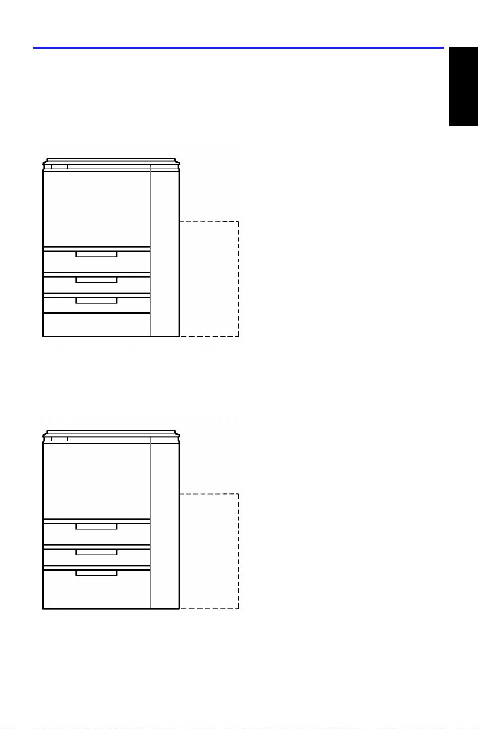
There are two types of mainfra me.
A095 copier
Three 550-sheet paper trays
Optional 3,500-sheet large capacity tray
Overall
Information
550
550
550
A096 copier
500 x 2 or 500
550
(3,500)
Tandem paper tray
(including two 500-sheet paper tray)
One 550-sheet paper t ray
1,500-sheet built-in large capa city tra y
Optional 3,500-sheet large capacity tray
(3,500)
1,500
1-5
Page 7
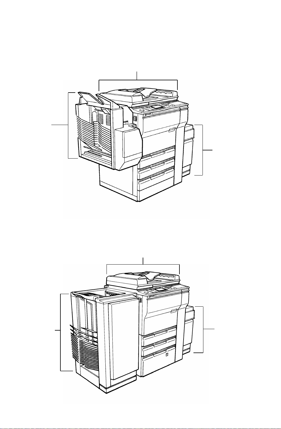
3,500-sheets
large capacity
tray (A380)
3,500-sheets
large capacity
tray (A380)
MACHINE CONFIGURATION 23 April 1993
2.2 SYSTEM OVERVI E W
System A
(The mainframe (A095) with du al job fee der and compa ct sorter stapler)
Dual job feeder (A376)
Compact
sorter stapler
(A374)
System B
(Mainframe type (A095/A096) with dual job feeder and floor type sorter
stapler. The mainframe in the illustrat ion belo w is the A096.)
Dual job feeder (A376)
Floor type
sorter stapler
(A377)
1-6
Page 8
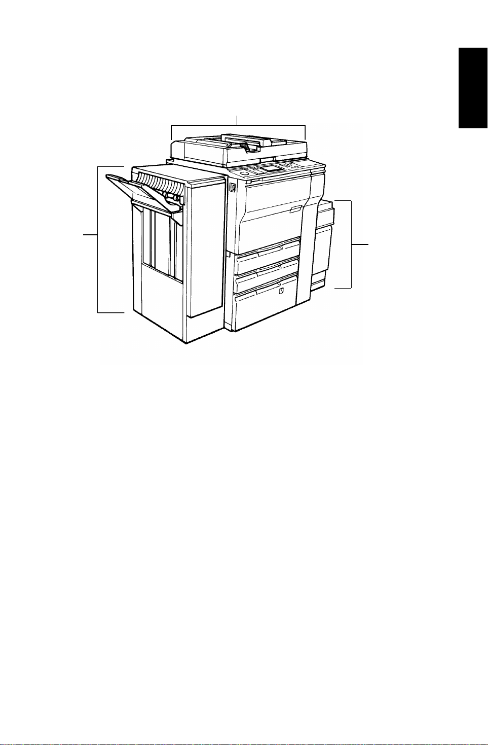
3,500-sheets
large capacity
tray (A380)
23 April 1993 MACHINE CONFIGURATION
System C
(The mainframe (A096) with recircu lating document handler and fin isher)
Finisher
(A379)
Recirculating document hand ler (A3 78 )
Overall
Information
1-7
Page 9
3
COPY PROCESS AROUND THE DRUM 23 April 1993
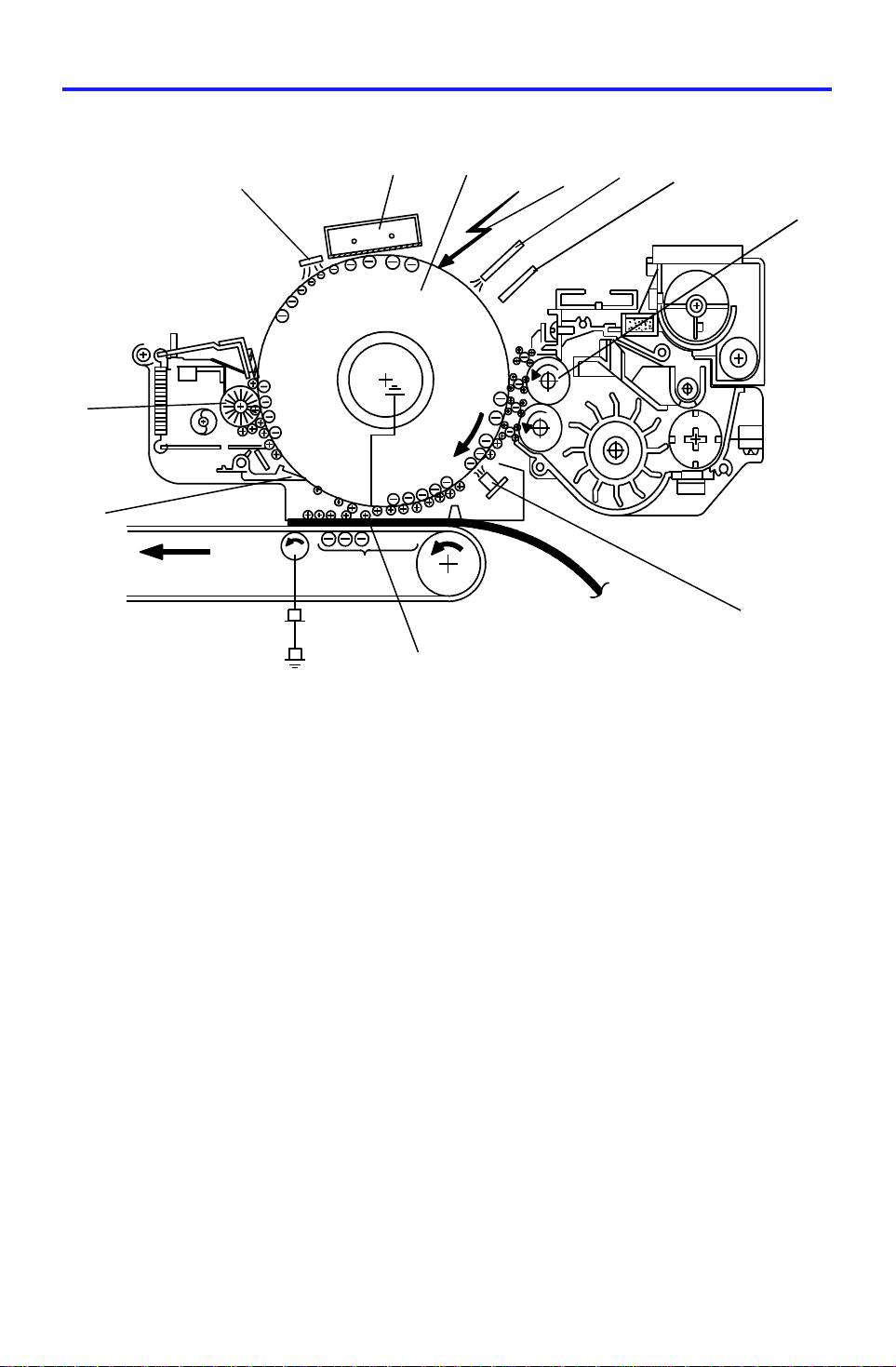
3. COPY PROCESS AROUND THE DRUM
10
11
12
9
8
4
5
6
7
1. OPC DRUM
The organic photo conductive (OPC) drum (10 0 mm diame te r) has hig h
resistance in the dark and low resistance under light.
2. DRUM CHARGE
In the dark, the charge corona unit gives a uniform negative ch arg e to the
OPC drum. The charge remains on the surfa ce of the drum. The amo unt of
negative charge on the drum is propo rtio na l to the ne gative grid bias voltage
applied to the grid plat e on the charg e coro na unit .
3. EXPOSURE
An image of the original is reflected to the OPC drum surfa ce via th e optics
section. The charge on the drum su rfa ce is dissipated in direct proportion to
the intensity of the reflected light, thus producing an electrical late nt ima ge on
the drum surface.
The amount of charge remainin g as a laten t imag e on the drum depe nds on
the exposure lamp intensity controlled by the exposure lamp voltage.
4. ERASE
The erase lamp illuminates the areas of th e cha rge d dru m su rfa ce th at will
not be used for the copy image. The resistance of drum in the illuminated
areas drops and the charge on those areas dissipates.
1-8
Page 10

23 April 1993 COPY PROCESS AROUND THE DRUM
5. DRUM POTENTIAL SENSOR
The drum potential sensor detects the electric potential on the drum to
compensate image processing elements.
6. DEVELOPMENT
Positively charged toner is attra cte d to the negat ively charged areas of the
drum, thus developing the latent ima ge. (The posit ive trib oe lect ric charg e of
the toner is caused by friction between the carrier and toner particle s.)
The development bias volt ag e ap plied to the developmen t rolle r shaft
controls two things:
1) The threshold level if tone r is attracted to the drum or toner remain s on
the development ro ller.
2) The amount of toner to be attracted to the drum.
The higher the negative develo pme nt bias volt ag e is, th e less toner is
attracted to the dru m surface.
7. PRE-TRANSFER LAMP (PTL)
The PTL illuminates the drum to remove almost all the negative charge from
the exposed areas of the dru m. This makes image transfer easier.
8. IMAGE TRANSFER
Paper is fed to the drum surface at the prop er timing so as to align the copy
paper and the develope d image on the drum surface. Then, a neg at ive
charge is applied to the reverse side of the copy paper by th e transfer belt,
producing an electrical force which pulls the toner particles from the drum
surface onto the copy paper. At the same time, the copy paper is electrically
attracted to the tra nsf er be lt.
Overall
Information
9. PAPER SEPARATION
Paper separates from the OP C drum by th e ele ctrica l att raction between the
paper and the transfer belt. The pick-o ff pawls help to separate the paper
from the drum.
10. CLEANING
The cleaning brush remo ves toner remaining on the dru m after image
transfer and the clean ing blade scrapes off all the rema ining toner.
11. QUENCHING
Light from the quenching lamp electrically neutralizes the charge pot ential of
the drum surface.
1-9
Page 11
11
29
30
8
MECHANICAL COMPONENT LAYOUT 23 April 1993
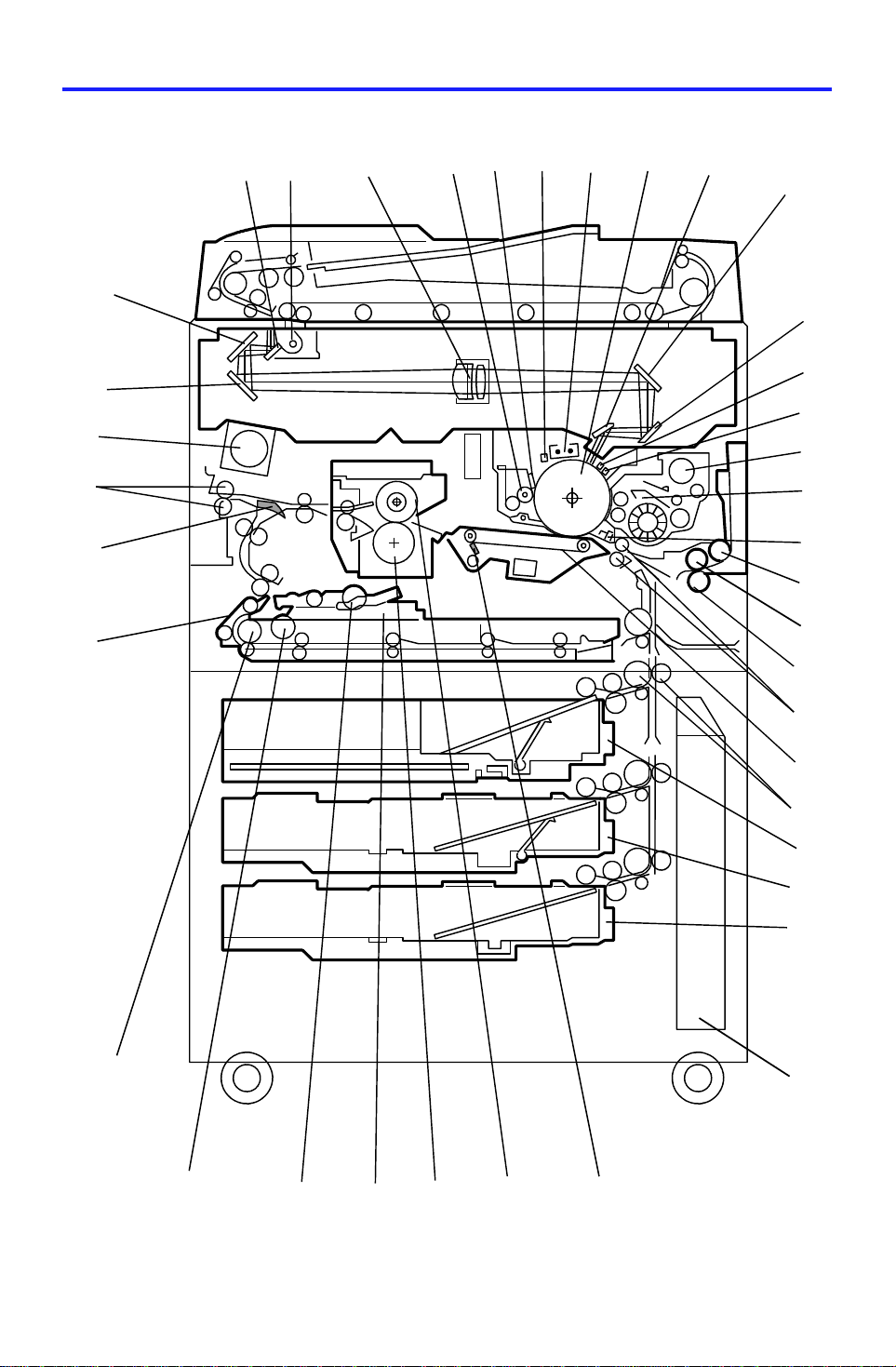
4. MECHANICAL COMPONENT LAYOUT
1
39
38
37
36
7
3
4
2
5
6
10
9
12
13
14
15
16
17
18
19
20
21
35
34
33
32
22
23
24
25
26
27
28
31
1-10
Page 12

23 April 1993 MECHANICAL COMPONENT LAYOUT
1. 3rd Mirror
2. 2nd Mirror
3. 1st Mirror
4. Exposure Lamp
5. Lens
6. Cleaning Brush
7. Cleaning Blade
8. Quenching Lamp
9. Charge Corona Unit
10. OPC Drum
11. 6th Mirror
12. 4th Mirror
13. 5th Mirror
21. Separation Roller
22. Registration Rollers
23. Transfer Belt
24. Vertical Transport Rollers
25. Tandem Tray (A096 copier)
550-sheet Tray (A095 copier)
26. Universal Tray
27. 1500-sheet LCT (A096 copier)
550-sheet Tray (A095 copier)
28. Toner Collection Bott le
29. Transfer Belt Cleaning Blade
30. Hot Roller
31. Pressure Roller
32. Jogger Fences
Overall
Information
14. Erase Unit
15. Drum Potential Sensor
16. Toner Hopper
17. Development Unit
18. Pre-Transfer Lamp
19. Pick-up Roller
20. Feed Roller
33. Duplex Positioning Roller
34. Duplex Pick-up Roller
35. Duplex Feed Roller
36. Separation Belt
37. Junction Gate
38. Exit Rollers
39. Optics Cooling Fan
1-11
Page 13
1
7
DRIVE LAYOUT 23 April 1993
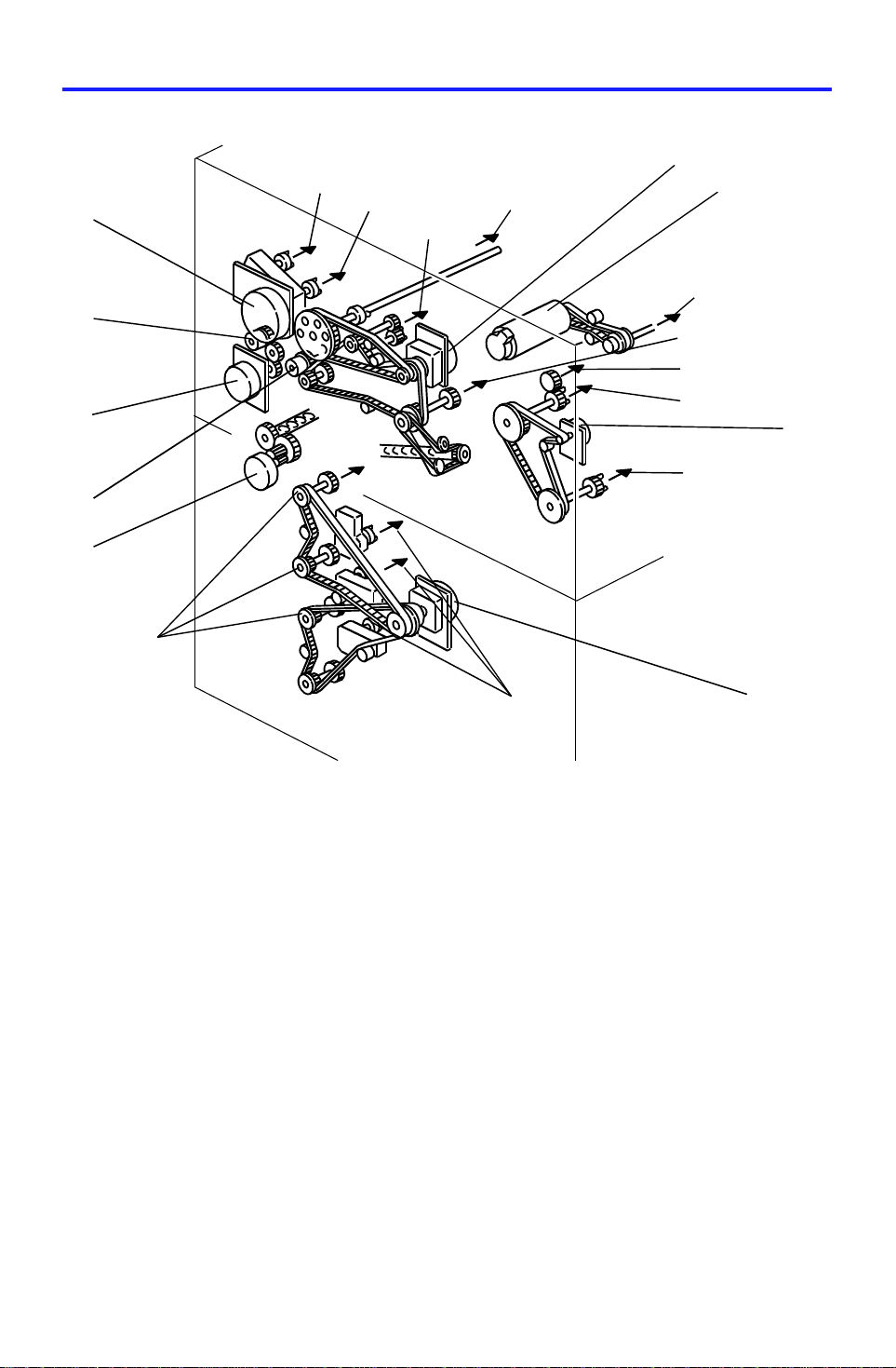
5. DRIVE LAYOUT
❾
❽
❼
❻
❺
❶
9
10
11
❷
2
3
4
5
❸
6
8
❹
❶ Main Motor
❷ Scanner Drive Motor
❸ Fusing/Duplex Drive Motor
❹ Paper Feed Motor
❺ Toner Collection Motor
❻ Registration Clutch
❼ By-Pass Feed Motor
❽ BY-Pass Feed Clutch
❾ Development Drive Motor
1. OPC Drum
2. Scanner Unit
3. Transfer Belt Unit
4. Paper Exit Unit
5. Fusing Unit
6. Duplex Unit
7. Paper Trays
8. Paper Feed Units
9. Toner Hopper
10. Development Unit
11. Cleaning Unit
1-12
Page 14
23 April 1993 PAPER PATH
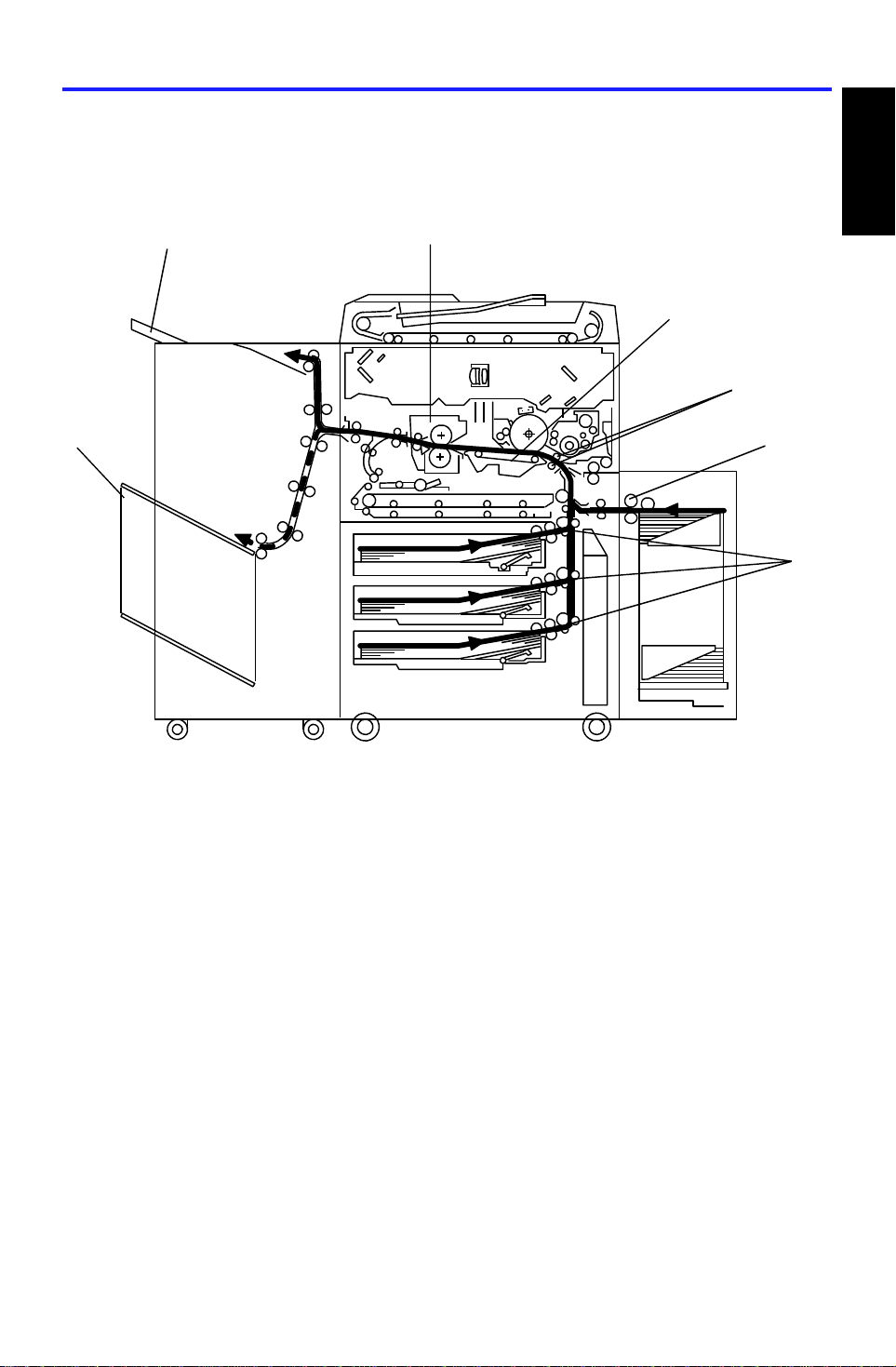
6. PAPER PATH
6.1 STANDARD COPYING
[F]
[D]
[C]
[B]
Overall
Information
[E]
Paper feed begins from the exte rior LCT, by-pa ss fee d ta ble or pap er fe ed
stations in the paper tray unit . The copy pa pe r the n follows on e of two path s
inside the copier. The path fo llowe d depe nd s on which mode the operator
has selected. For copy processing, all sheets follow the same pat hs fro m t he
paper feed mechanism [A] through the registration rollers [B ], transfer belt
[C], and fusing unit [D] . Af ter that, copies are delivere d to the sorter bins [E]
or proof tray [F], however, 2 sided copie s are diverted for further processing.
[A]
[A]
1-13
Page 15
PAPER PATH 23 April 1993
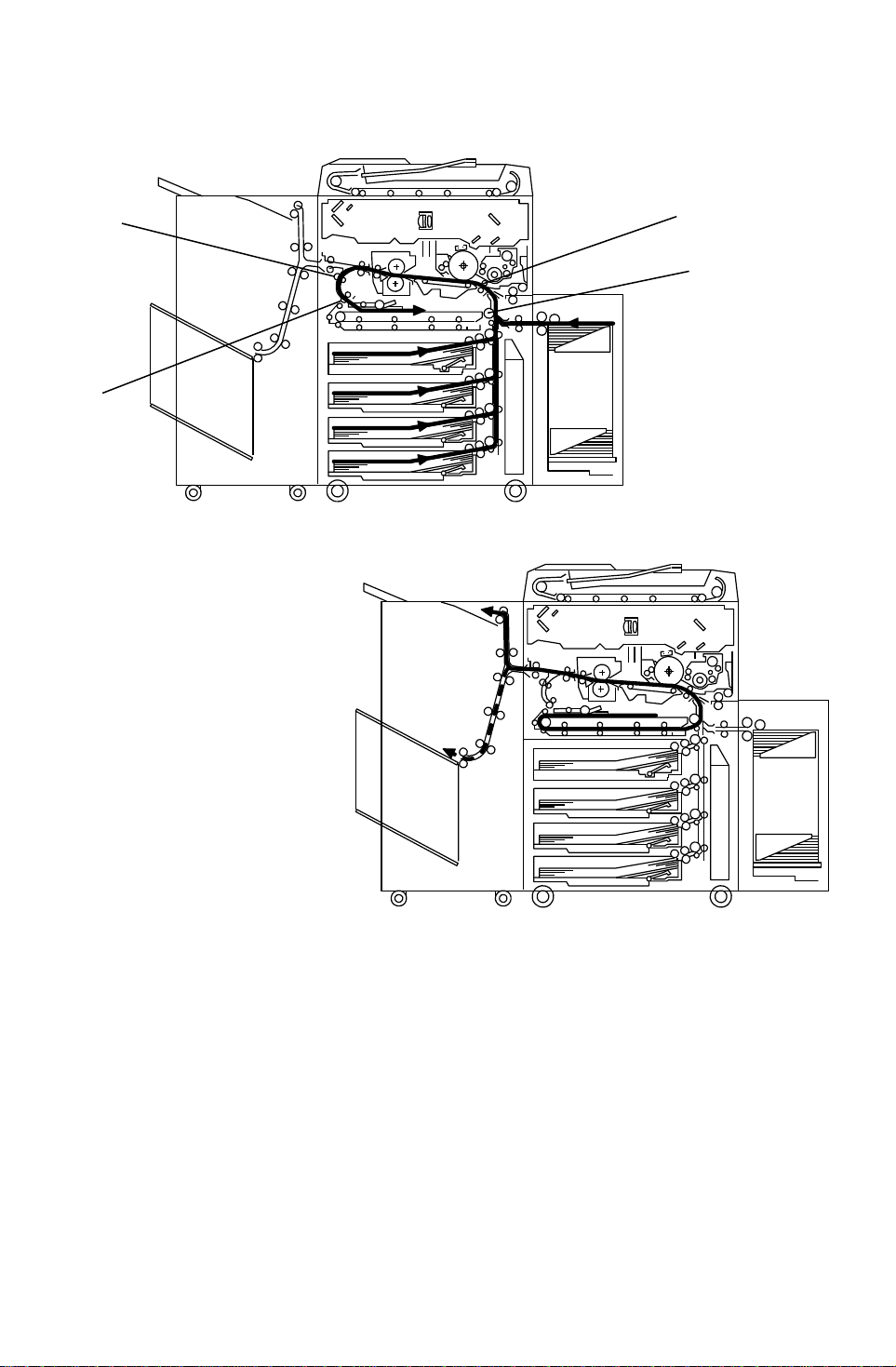
6.2 MULTIPLE 2-SIDED CO PYING
a. Front Side
[B]
[A]
[D]
[C]
b. Rear Side
In this mode the junction gat e [A ] directs sheets exiting th e fu sing unit to the
duplex tray entrance. Aft er that, all sheets follo w the pat h th rou gh the dup lex
entrance rollers [B].
After all front side cop ying is comp let ed , the sheets on the duple x tray are fed
in order from the bottom to the top and follow the path throu gh the duplex
feed mechanism and vertical transport rollers [C] to the registration rollers
[D]. After that , th ese sheets follow the same pat h as sta nd ard copying from
the registration rollers to the sorter.
1-14
Page 16

23 April 1993 ELECTRICAL COMPONENT DESCRIPTION
7. ELECTRICAL COMPONENT DESCRIPTION
Refer to the electrical compone nt layou t on the reverse side of the att ach ed
Point to Point for symbols and ind ex numbers.
Symbol Name Function Index
No.
Motors
Overall
Information
M 1 Scanner Drive Drives the 1st and 2nd scanne rs
(dc servo).
M 2 Exhaust Fan Removes the heat from around
the fusing unit.
M 3 Main Drives the main unit components. 44
M 4 Development Drive Drives the development unit. 45
M 5 By-pass Feed Drives the by-pass feed rollers. 46
M 6 3rd Scanner Drive Drives the 3rd scanner (dc
stepper)
M 7 Toner Bottle Drive Rotates the toner bottle to supply
toner to the toner hopper.
M 8 Charge Wire Cleaner
Drive
M 9 Jogger Drives the jogger fences to
M10 Lens Horizont al Drive Shifts the lens horizontal position. 51
M11 Lens Vertica l Drive Shifts the lens vertical position . 52
Drives the main charge wire
cleaner to clean the charge wire.
square the paper stack in th e
duplex tray (dc stepper).
42
43
47
48
49
50
M12 Optic Cooling Fan Removes heat from the optics
unit.
M13 Fusing/ Duplex Drive Drives the fusing unit, the duplex
unit, and the paper exit rollers.
M14 Paper Feed Drives all feed and transport
rollers in the paper tray unit.
M15 1st Lift Raises the bottom plate in the 1st
paper tray.
M16 2nd Lif t Raises the bottom pla te in the
2nd paper tray.
M17 Toner Colle ction Transport s the collect ed toner to
the toner collection bott le.
1-15
53
54
90
91
92
93
Page 17

ELECTRICAL COMPONENT DESCRIPTION 23 April 1993
Symbol Name Function Index
No.
M18 3rd Lift
(A095 copier only)
M19 Side Fen ce Drive
(A096 copier only)
Raises the bottom plate in the 3rd
paper tray.
Opens and closes the front and
the rear side fences of the
tandem tray.
M20 Rear Fence Drive
(A096 copier only)
Moves the papers stacked in the
left tandem tray to the right
tandem tray.
M21 LCT Motor
(A096 copier only)
Lifts and lowers the LCT bottom
plate to bring paper to the feed
position and allow loading of the
paper.
Magnetic Clutches
MC1 Toner Supply Turns the toner supply roller to
supply toner to the development
unit.
MC2 Registration Drives the registration rollers. 58
94
95
96
127
57
MC3 By-pass Feed Starts paper feed from the
by-pass feed table.
MC4 Duplex Transport Drives the duplex tra nsport rollers
to transport the paper to the
vertical transport rollers.
MC5 Duplex Feed S tarts pa per fee d from the duplex
tray to the duplex transport rollers.
MC6 1st Feed Starts paper fee d from the 1st
feed tray.
MC7 2nd Feed Starts paper feed from the 2nd
feed tray.
MC8 3rd Feed Starts paper feed from the 3rd
feed tray.
60
64
65
99
101
104
1-16
Page 18

23 April 1993 ELECTRICAL COMPONENT DESCRIPTION
Symbol Name Function Index
No.
Switches
SW1 By-pass Table Detects if the by-pass feed tab le
is open or closed.
SW2 Front Door Safety Cuts the ac power line and
detects if the front door is open or
not.
SW3 1st Tray Set
Detects if the 1st tray is set or no t. 66
(A095 copier only)
SW4 2nd Paper Size Determines what size paper is in
the 2nd (universal) paper tray.
SW5 Toner Overflow Detects when the toner collection
bottle is full.
SW6 Toner Collection
Bottle Set
SW7 Lower Front Door
Safety
SW8 3rd Tray Set
Detects if the toner collection
bottle is set or not.
Detects if the front door is open
or not.
Detects if the 3rd tray is set or no t. 84
(A095 copier only)
25
29
67
75
77
83
Overall
Information
SW9 Main Provides power to the copier 122
SW10 Tray Down
Lowers the LCT bottom plate. 126
(A096 copier only)
Solenoids
SOL 1 Junction Gate Moves the junction gate to dire ct
copies to the duplex t ray or to the
paper exit.
SOL 2 Duplex Positioning Controls the up-down move ment
of the positioning roller.
SOL 3 By-pass Pick-up Controls the up-down movemen t
of the pick-up roller for by-pass
feed.
SOL 4 Guide Plate Opens the guide plate when a
paper misfeed occurs around this
area.
SOL 5 Transfer Belt
Positioning
Controls the up-down movement
of the transfer belt un it.
55
56
59
61
62
1-17
Page 19

ELECTRICAL COMPONENT DESCRIPTION 23 April 1993
Symbol Name Function Index
No.
SOL 6 Pressure Arm Presses the paper on the duplex
tray against the duple x fee d
rollers.
SOL 7 Tandem Lock Locks the left tandem feed tray
and separates the righ t an d lef t
tandem trays.
SOL 8 1st Pick-up Controls the up-down movemen t
of the pick-up roller in the 1st
feed station.
SOL 9 1st Separation Roller Controls the up-down movement
of the separation roller in the 1st
feed station.
SOL10 2nd Pick-up Controls the up-do wn movement
of the pick-up roller in the 2nd
feed station.
SOL11 2nd Separat ion Roller Controls the up-down movement
of the separation roller in the 2nd
feed station.
SOL12 3rd Pick-up Controls th e up -do wn movement
of the pick-up roller in the 3rd
feed station.
63
97
98
100
102
103
105
SOL13 3rd Separa tio n Rolle r Controls the up-down move men t
of the separation roller in the 3rd
feed station.
Sensors
S 1 Scanner HP Informs the CPU when the 1st
and 2nd scanners are at the
home position.
S 2 Platen Cover
Position–1
Informs the CPU that the platen
cover is in the up or down
position (related to APS/ARE
function).
S 3 Platen Cover
Position–2
Informs the CPU that the platen
cover is in the up or down
position to detect if th e original
has been removed or not.
106
1
2
3
1-18
Page 20

23 April 1993 ELECTRICAL COMPONENT DESCRIPTION
Symbol Name Function Index
No.
S 4 Lens Vertical HP Informs the CPU that the lens is
at the full-size position.
S 5 Lens Horizontal HP Informs the CPU that the lens is
at the horizontal home position.
S 6 3rd Scanner HP Informs the CPU when the 3rd
scanner is at the home position.
S 7 By-Pass Paper End Informs th e CPU that there is no
paper in the by-pass feed tab le.
S 8 Guide Plate Position I nforms th e CPU if the
registration guid e pla te is closed
or not.
S 9 Jogger HP Detects if the duplex jogg er
fences are at the home position
or not.
S10 Vertical Transport Detects the leading edge of the
paper to determine the paper
feed timing of the next sheet.
S11 Duplex Exit Detects the leading edge of the
paper to determine the duplex
transport clutch on timing .
4
Overall
Information
5
6
7
8
9
10
11
S12 Duplex Entrance
Sensor
Detects the leading edge of the
paper to determine the duplex
12
feed clutch off timing.
S13 Duplex Paper End Detects paper in the duplex tray. 13
S14 Duplex Transport Detects the lea din g ed ge of th e
14
paper to control the jogger motor
and the positioning solenoid on
timing.
S15 Exit Detects misfeeds. 15
S16 Fusing Exit Detects misfeeds. 16
S17 Paper Guide Detects misfeeds. 17
S18 Auto Image Density Senses the ba ckgro un d de nsit y
20
of the original.
S19 Original Length–1 Detects original length. 21
S20 Original Length–2 Detects original length. 22
S21 Original Width Detects original width. 23
1-19
Page 21

ELECTRICAL COMPONENT DESCRIPTION 23 April 1993
Symbol Name Function Index
No.
S22 By-Pass Paper Size Informs the CPU what size pape r
26
is in the by-pass feed table.
S23 Toner Density Senses the amount of toner in th e
27
black developer.
S24 Registration Detects misfeeds and controls
28
registration clutch off-on timing.
S25 Toner End Detects toner end cond itio n. 30
S26 Auto-Response Returns the display fro m the
34
screen saver.
S27 Drum Potential Detects the drum surface
39
potential.
S28 Image Density Detects the density of the ID
41
sensor pattern on the drum.
S29 1st Paper End Informs the CPU when the 1st
68
cassette runs out of paper.
S30 1st Paper Near End Informs the CPU when the 1st
69
cassette is in near end condition.
S31 1st Paper Feed Controls the 1st paper feed clutch
70
off/on timing and the 1st pick-up
solenoid off timing.
S32 2nd Paper Near End Informs the CPU when the 2nd
cassette is in near end condition.
S33 1st Lift Detects the correct fe ed heig ht of
the 1st cassette.
S34 2nd Paper End Informs the CPU when the 2nd
cassette runs out of paper.
S35 Toner Collection
Motor
Detects the toner co llect ion motor
operation.
S36 2nd Lift Detects the correct fe ed heig ht of
the 2nd cassette.
S37 3rd Lift Detects th e correct feed height of
the 3rd cassette.
S38 3rd Paper Near End
(A095 copier only)
Informs the CPU when the 3rd
cassette is in near end condition.
S39 3rd Paper End Informs the CPU when the 3rd
cassette runs out of paper.
71
72
73
74
76
78
79
80
1-20
Page 22

23 April 1993 ELECTRICAL COMPONENT DESCRIPTION
Symbol Name Function Index
No.
S40 3rd Paper Feed Controls the 3rd paper feed
clutch off/on timing and the 3rd
pick-up solenoid off timing.
S41 2nd Paper Feed Controls the 2nd paper feed
clutch off/on timing and the 2nd
pick-up solenoid off timing.
S42 Base Plate Down
(A096 copier only)
Detects when the bottom plate is
completely lowered to stop the
1st lift motor.
S43 Side Fence
Positioning
Informs the CPU when the
tandem tray side fences are open.
(A096 copier only)
S44 Rear Fence Return
(A096 copier only)
Informs the CPU when the
tandem tray rear fence is in the
return position.
S45 Rear Fence HP
(A096 copier only)
Informs the CPU when the
tandem tray rear fence is in the
home position.
S46 Left Tandem Paper
End
Informs the CPU when the left
tandem tray runs out of paper.
(A096 copier only)
81
Overall
Information
82
85
86
87
88
89
S47 LCT Near End
(A096 copier only)
S48 Tray Down
(A096 copier only)
Detects the paper nea r e nd
condition.
Detects when the tra y is
completely lowered to stop the
LCT motor.
S49 Tray Paper Set
(A096 copier only)
Informs the CPU when the paper
is set on the LCT bottom tray.
PCBs
PCB 1 AC Drive Provides AC power to the
exposure lamp and fusing lamp.
PCB 2 Main Controls all machine fun ctio ns. 109
PCB 3 Optic Control Controls all optics components. 110
PCB 4 High Voltage Con tro l Controls the output of both power
packs and development bias.
123
124
125
108
111
1-21
Page 23

ELECTRICAL COMPONENT DESCRIPTION 23 April 1993
Symbol Name Function Index
No.
PCB 5 Paper Feed Cont rol Controls all components in the
paper bank.
PCB 6 DC Power Supply
Provides DC power. 113
Unit
PCB 7 Guidance Controls the guidance displa y. 120
PCB 8 Operation Panel Controls the LED matrix, and
monitors the key matrix.
Lamps
L1 Exposure Applies high intensity light to the
original for exposure.
L2 Fusing Provides heat to the hot roller. 32
L3 Quenching Neutralizes any charge remaining
on the drum surface after
cleaning.
L4 Erase Discharg es th e drum outside the
image area.
L5 Pre-transfer Reduces the charge on the dru m
surface before transfer.
112
121
18
37
38
40
Power Packs
PP1 Transfer Provides high voltage for the
transfer belt and controls the
transfer belt positioning solenoid.
PP2 Charge Provides high voltage for the
charge corona wires, and the grid
plate. Controls QL, PTL, and
charge wire cleaner motor
functions.
Others
TS1 Optics Thermoswitch Opens the exposure lamp circuit
if the optics unit overheats.
TF1 Fusing Thermofuse Opens the fu sing lamp circuit if
the fusing unit overhe at s.
TH1 Fusing Thermistor Senses the temperat ure of the
hot roller.
117
119
19
33
24
1-22
Page 24

23 April 1993 ELECTRICAL COMPONENT DESCRIPTION
Symbol Name Function Index
No.
TH2 Optics Thermistor Monitors the temperature of the
36
optics cavity.
TH3 Drum Thermistor
(Located on the ID
Monitors the tempe rature of the
OPC drum.
41
Sensor Ass’y)
H1 Transfer
Anti-Condensation
Turns on when the main switch is
off to prevent moisture from
31
forming on the transfer belt.
H2 Optics
Anti-Condensation
Turns on when the main switch is
off to prevent moisture from
35
forming on the optics.
RA1 Main Power Relay Controls main power. 107
CO1 Total Counter Keeps track of the total number of
114
copies made.
NF1 Noise Filter Removes electrical noise. 115
CB1 Circuit Breaker Provides back-up high current
116
protection for the electrica l
components.
Overall
Information
LA1 Lightening Arrestor Removes current surg es fro m the
AC input lines.
118
1-23
Page 25

SECTION 2
DETAILED SECTION
DESCRIPTIONS
Page 26
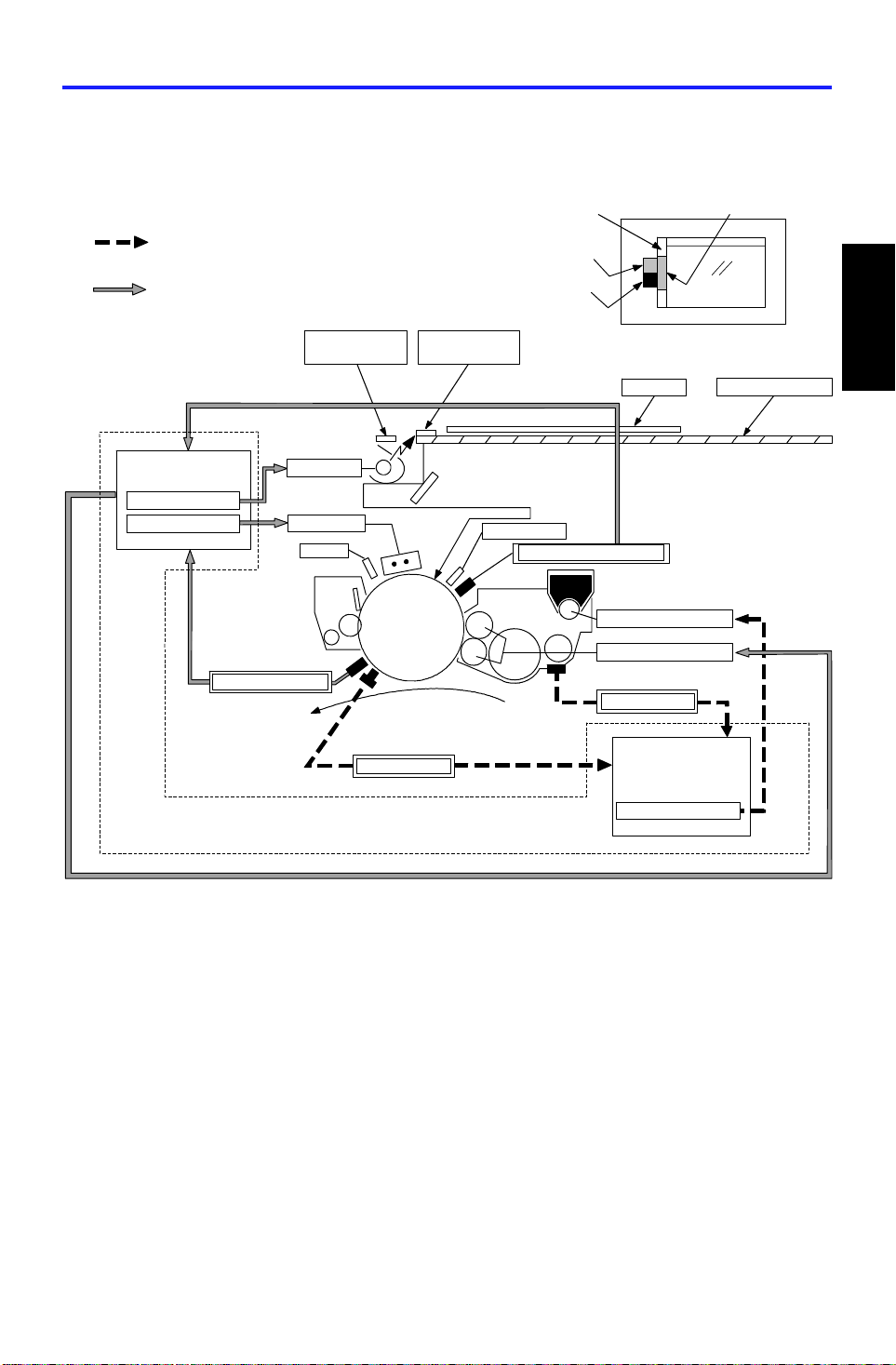
VL Pattern
Original
Toner Supply On time
Development. Bias
TD Sensor
Image Density Control
23 April 1993 PROCESS CONTROL
1. PROCESS CONTROL
1.1 OVERVIEW
Original Scale
Image Density Control
(Fuzzy Control)
Latent Image Control
ADS Pattern
VD Pattern
Latent image Control
Exposure Control
Charge Control
Temperature Sensor
Main PCB
Lamp Voltage
Grid Voltage
Paper
VD Pattern
QL
ID Sensor
VL Pattern
Erase Lamp
Drum Potential Sensor
(Fuzzy Control)
Toner Supply Control
Exposure Glass
Detailed
Descriptions
This model uses two process control methods. One compensates for
variation in the drum potential (latent image control) and the othe r con tro ls
the toner concentratio n an d tone r supply a mou nt (image density control).
2-1
Page 27

Erase
VD
PROCESS CONTROL 23 April 1993
1.1.1 Latent Image Control
QL
Charge
Vo
Exposure
Black White
VL
Potential
Sensor
VR
Drum
The figure shows the changes of the drum pote nt ial du ring the copy process.
Vo: The drum potential just afte r charg ing the drum.
VD (Dark Potential): The drum potential just after exposing the black
pattern (VD pattern)
VL (Light Potential): The drum potential ju st af ter exposing the white
pattern (VL pattern)
VR (Residual Voltage ): The drum potential just after t he expo sure of the
erase lamp.
After long usage following installation or a PM, drum potentia l will gra dually
increase due to the following factors:
Dirty optics or exposure lamp deterioration
Dirty charge corona wire and grid plate
Change of the drum sensitivity
In this copier, th e change in drum potential is detected by the drum potentia l
sensor and the following it ems are cont rolle d to maint ain goo d cop y quality.
The grid bias voltage
The exposure lamp voltage
The development bias voltage.
A drum thermistor detects the drum tempera ture an d this data is also use d to
control the above voltages. It is impossible to explain simply because it is
controlled by methods developed in our laboratories using an artificia l n eural
network.
2-2
Page 28

23 April 1993 PROCESS CONTROL
1.1.2 Image Density Control
Image density is controlled by the following sensors:
Toner density sensor (TD sensor)
Image density sensor (ID sensor)
Data from the TD sensor is used to keep the toner con centration in the
developer at a constant level. However, the image on the OPC drum varies
due to the variation of toner charge ab ility (inf luenced by the environment)
even if the toner concentration is constant. By the ID sensor compensation,
toner concentratio n is change d to keep the ima ge den sity on the OPC dru m
constant.
The following items are contro lled to main ta in a con sta nt copy imag e density:
Toner supply clutch on time
Detailed
Descriptions
Toner supply level data (VREF) of the TD sensor
2-3
Page 29

PROCESS CONTROL 23 April 1993
1.2 PROCESS CONTROL DATA INITI AL SE TTI NG
The following flow chart shows all the steps that will be perf orme d whene ver
the machine is turned on while the hot ro ller te mpe rature is below 100°C.
This initializes all the process control sett ings.
Main SW On (Fusing Temp. < 100°C)
Charge wire cleaning (if more than 5 K copie s are mad e since
last cleaning
Drum Potential Sensor Calibration
①
Drum Conditioning Start (Fusing Temp . = 180° C)
VSG Adjustment
VR Measurement
VD/VL Correction
TD Sensor Detection
②
ID Sensor Detection/Correctio n
③
ADS Adjustment
① : See Latent Image Control section (Page 2-5) for details.
② : See Image Density Control section (Pa ge 2-12 ) for deta ils.
③: See Optics section (Page 2-3 9) for details.
2-4
Page 30
23 April 1993 PROCESS CONTROL
1.3 LATENT IMAGE CONTROL
1.3.1 Drum Potential Sensor Calibra tion
[A]
RA601
-100 V
RA602
-800 V
Drum
[B]
Case
Sensor
Output
Amp.
Detailed
Descriptions
Main PCB
The drum potential se nso r [ A] is located just above the development unit. The
sensor has a detector which dete cts th e stre ngth of the ele ctric field from the
electric potential on the drum. The output of the sensor depends on the
strength of the electric field.
Since the output of the sensor is affected by environmental conditions, such
as temperature and humidity, the sensor outp ut is calibrat ed durin g pro cess
control data initial setting.
The High Voltage Contro l PCB [B] has two relay contacts. Usually RA 602
grounds the drum. However, during the initial setting, th e main PCB tu rns
RA601 on and RA602 off an d ap plie s t he volta ge to th e drum shaft.
By measuring the output of the drum po te ntial sensor when –100 V and –800
V are applied to the drum, the sensor output is calibrated auto mat ically.
(The machine recognize s t he re lat ionship between actua l drum po te ntial and
the potent ial sensor output.)
2-5
Page 31

VR
Light
New Drum
Used Drum
PROCESS CONTROL 23 April 1993
1.3.2 Drum Conditioning
When the fusing tempe r at ure reaches 180°C, the machin e sta rts the drum
conditioning proc ess. In th is mo de , th e main motor, main charge corona ,
erase lamp and developme nt bias are activated for about 30 second s and
drum sensitivity and residual volt age (VR) are stabilized , as in con tin uo us
copy runs.
1.3.3 VSG Adjustment
During drum conditioning , th e ID sen sor checks the bare drum’s reflectivity
and calibrates the output of the ID sensor to 4 ±0.2 V.
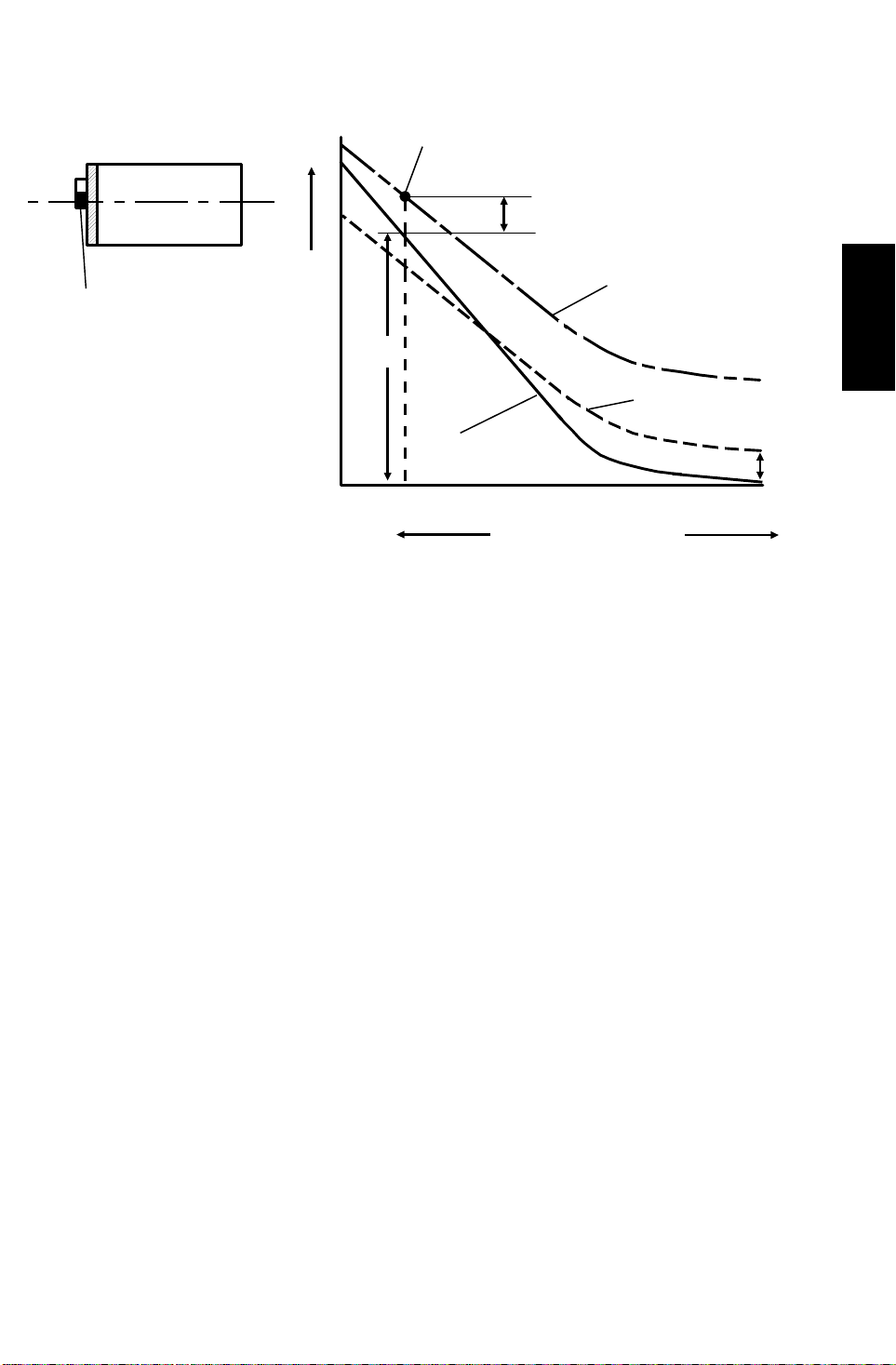
1.3.4 VR Measurement
Drum
Potential
[V]
[–V]
Vo
VD
VL
Original DensityDark
The above figure shows t he relationship between th e dru m pot en tia l a nd the
original density. To get consta nt copy quality, this relation ship must be
maintained.
Since this relationsh ip te nd s to cha ng e to the one represente d by th e do tted
line by various factors, compen sat ions are required.
The residual voltage (VR) cannot be compensated even if the exposure lamp
voltage is increased. Therefore, the VR change has to be compensated by
other means.
The main control board checks th e drum potential just afte r t he erase lamp
exposure by the drum pote nt ial sensor after drum conditioning. This
measured drum potential is in fact VR. This VR is used as the standard for the
VD and VL corrections.
NOTE: In the figu re ab ove, the residual voltage (VR) for the new drum is
0V. Actually, there is some re sidu al voltage even on the new
drum.
2-6
Page 32
Original Density
23 April 1993 PROCESS CONTROL
1.3.5 VD Correction
[-V] VD
Exposure
Glass
VR
VD Pattern
Drum
Potential
VD Compensated
–770
After many copies
New Drum
VR
Dark
Light
The drum potential ju st af ter the black pattern (VD Pattern) is exposed (VD:
Dark Potential) tends to lo wer during drum life due to a decrease in the
drum’s capacity to carry a charge.
To check the actual VD , th e first scanner moves to the home position and the
VD pattern (Black) stuck on the bottom side of the exposure glass bracket is
exposed on the drum.
The main control board measures VD through the drum potential sensor and
adjusts it to a target value by adjusting the grid bias voltage (V G RID).
Detailed
Descriptions
On the other hand, ther e is a chan ge of th e dru m residual voltage (VR), so
that the target VD voltage is compensa te d as follows:
Target VD Value : VD = VR + (–770)
The adjusted grid bias voltage (VGRID) is kept in memory until the next
process control data initial setting.
2-7
Page 33

PROCESS CONTROL 23 April 1993
1.3.6 VL Correction
[-V]
Exposure
Glass
VL Pattern
Drum
Potential
–770
Dark
Dirty optics and/or exposure lamp deteriora tio n decrea ses th e int ensity of the
light that reaches the drum. In addit ion to this, the drum sensitivity also
changes during the drum’s life. These factors change the drum potential ju st
after white pattern exposure (VL : Light Potential).
VD
VR
–140
VR
VL
Original Density
Only VD
Compensated
VD and VL
Compensated
New Drum
VR
Light
To check the actual VL , the first scanner moves under th e VL pattern (White)
stuck underneath th e orig inal scale. The pattern is exposed on the drum.
The main control board measures VL through the drum potential sensor and
adjusts it to a target value by adjusting the exposure lamp voltage (VLAMP).
The residual voltage (VR) change also affe cts V L, so that VL’s target voltage
is compensated as follows:
Target VL Value : V L = VR + (–140)
The adjusted exposure lamp voltage (VLAMP) is stored in memory unt il the
next process control data initial setting.
2-8
Page 34

23 April 1993 PROCESS CONTROL
1.3.7 VR Correction
[-V]
VD
Drum
VD and VL Compensated
Potential
VR
VL
Development Bias (VBB)
New Drum
–770
VR
–140
VR
Dark
Original Density
Light
Potentials (VR, VD, VL) are mon itored by the potential sensor. (This is don e
only when the fusing temp erature is less than 100°C after t he machine is
turned on.)
During the check cycle, the VD and VL patterns are exposed and the drum
potential on th e are a where exposed by each pa tt ern is checked by the
potential sensor.
Compare the curve of the VD and V L compensated drum potential with the
curve of the new drum, they are para llel but the compensated potentia l is still
higher (VR) than the new drum p oten tia l. To prevent dirty backgrounds due to
increased residual po te ntial, development bias (VBB) is applied as follows:
Detailed
Descriptions
VBB= VR + (–220)
2-9
Page 35

New VL
PROCESS CONTROL 23 April 1993
1.3.8 Initial Setting Sequence
The following graph shows the seque nce of eve nt s durin g pro cess con trol
data initial setting.
Scanner
Motor
Exposure
Lamp
Potentia l
Sensor
Output
forward
reverse
V800
V100
1. Potential
sensor
calibration
VD New VD
VL
VR
New VR
2. VR’, VD’, VL’
potential
detection
Latent Image Control
3. VD, VL
correction
for the purpose
of ADS sensor
correction
4. ID sensor
pattern
potential
detection
1. Potential sensor calibration
By measuring the output of the drum po te ntial sensor when –100 V and
–800 V are applied to the dru m , th e sensor output (V 100 and V800) is
calibrated automatically (See page 2-5 for details).
2. VR, VD, VL potential detection
After about 30 seconds of drum conditioning, VD and VL Patterns are
developed by using the previous grid bias voltage (VGRID) data and
exposure lamp voltage (V LAMP) da ta to detect the VR, VD, VL data .
The machine calculate s the new VGRID and VLAMP data using the
detected VR, VD, VL data.
2-10
Page 36

23 April 1993 PROCESS CONTROL
3. VD and VL corrections
Using the calculated VGRID and VLAMP data, VR, VD, and VL patterns are
developed again and the new VR, VD, and VL data are detected.
If both VD and VL data are within specificat ions, the new V GRID, VLAMP
and development bias (VBB) are determined based on the new VD, V L,
and VR values.
Specifications:
VD = –770 + VR ± 20 V
VL = –140 + VR ± 20 V
If VD is outside specifications, VGRID is shifte d on e step. Then the VD pattern
is measured again and VD is detected again.
The same is done for VL and VLAMP.
The above process continues until both V D and VL fall within spe cifica tions.
The graph on the previou s pag e sho ws t he examp le whe n on ly VL was
outside specifications at the first VL detection and it became within
specifications after on e V L corre ction (VLAMP is changed 0.5V/step , VGRID is
changed 20 V/step).
If V100 or V800 at drum potential sensor calibration is outsid e spe cifica tions or
if VD or VL do not fall within specificat ions after VGRID or VLAMP are shifted to
the maximum or minimum level, the machine stops VD or VL correction and
uses the previous V GRID and VLAMP values during copying.
In this case, nothing is in dica ted on the machine but the SC counter is
incremented.
Related SC codes (see troublesh oo tin g section for details):
Code Condition
361 Incomplete drum potential sensor
calibration
364 Abnormal VD detection
Detailed
Descriptions
365 Abnormal VL detection
Development bias is also de cide d by using VR as follows.
VBB = VR + (–220)
4. ID sensor pattern potential detection
This is performed to determine ID Sensor Bias Volt age. The details are
explained in the develo pment control section (se e page 2-16).
2-11
Page 37

VD (12 V)
GND
PROCESS CONTROL 23 April 1993
1.4 IMAGE DENSITY CONTROL
1.4.1 Toner Density Sensor
A: VOUT (Gain data) is high.
OUT is within the specification.
B: V
OUT (Gain data) is low.
C: V
A
B
VOUT = VIN x
New Developer
1234
Toner Weight %
= 12 x
V
IN
Main PCB
VOUT
AGC
Gain
256
Gain
256
TD
Sensor
Sensor
Output
Sensor
Output
(V)
5
C
4
3
REF
V
2
1
0
Developer consists of carrier particles (iron ) and toner particle s (re sin and
carbon). Inside th e de velo pment unit, developer passes through a magnetic
field created by coils inside the ton er de nsit y senso r. When the toner
concentration chan ge s, th e voltage output by the sensor changes accordingly.
<Toner Density Sensor Initia l Setting>
When new developer with th e sta nd ard toner concentratio n (2.0% by weight,
20 g of toner in 1000 g of developer) is installed, developer initial settin g must
be performed by using SP mod e ( SP Adjustment – PAG E 1).
1
During this setting, the outpu t volt ag e (VOUT) from the auto gain control
circuit (AGC) on the main control board PCB varies to cha nge the output
voltage from the toner density (TD) senso r. This is don e by cha ng ing the gain
data, see below.
VOUT = VIN x
Gain Data
256
= 12 x
Gain Data
256
If the data is high, VOUT becomes high, and the sen sor ou tp ut
voltage becomes high. As a result, the sensor characteristic
becomes as illustrated by curve A. If the data is low, VOUT
becomes low, and the sensor ou tput voltage becomes low. As a
result, the sensor characte ristic shifts as illustrated by curve C.
2-12
Page 38

23 April 1993 PROCESS CONTROL
By selecting the proper ga in da ta , the sensor output is set wit hin the targeted
control level (VREF, VREF = 2.5 ± 0.1 V). Now, the sensor characteristic is
illustrated by curve B and the TD sensor initial settin g is comple ted.
The selected gain data is sto red in me mory, and VOUT from the auto gain
control circuit stays consta nt during the toner senso r d et ect ion cycle.
<Toner Supply Criteria>
At every copy cycle, toner density in the deve lop er is det ect ed once . The
sensor output voltag e (VTD) during the detectio n cycle is compared with the
toner supply level voltage (VREF).
5
4
Sensor
V
Output
(V)
3
TD
Detailed
Descriptions
V
2
1
REF
0
12345
Toner Weight %
2-13
Page 39

PROCESS CONTROL 23 April 1993
<Toner Supply Clutch on Time>
To stabilize toner concentrat ion , to ne r supp ly amou nt (t oner supply clutch on
time) is controlled by referring to V REF and VTD.
The toner supply amount is calculated at every copy. The toner supply
amount is determined by using the following factors.
① VREF – VTD
② VREF – VTD’(VTD’ = VTD of the previou s copy cycle)
VTD’
Previous Copy Last Copy Next Copy
VTD
VREF
By referring to these fact ors, the machine recognizes th e difference between
the current toner concentration and the target toner concentration. The
machine also understan ds ho w much toner concentration has changed and
predicts how much the toner supply amount will probably cha nge.
By changing the toner supply amount precisely, toner concentration (image
density) is kept at a constant level.
Since the toner supply clutch on time up dating is under fuzzy control, the
relation among VTD, VTD’, VREF cannot be expressed by a simple algebraic
formula.
<VREF Correction>
The image on the OPC drum changes due to varia tio n of ton er cha rgeability
(influenced by the environment) even if the toner concentration is constant.
The image density sensor (ID sensor) direct ly checks th e image on the OPC
drum and shifts VREF data (under fuzzy control) to keep the image on the
OPC drum constant, as expla ined in the next section.
NOTE: 1. Toner end cond ition is detected by the toner en d sen sor (see the
development sect ion for de tails).
2. The toner supply clutch turns on at the inte rvals be twe en each
copy process while image develop men t is not perf ormed.
2-14
Page 40

3rd Series of
Copies (17
copies)
23 April 1993 PROCESS CONTROL
1.4.2 Image Density Sensor Dete ction
[B]
[C]
[A]
Drum
bias
V
LED
ON
SG
4 V
LED
V
ON
SP
VSG and VSP are checked by the ID senso r [A] . The ID se nso r is located
underneath the drum clea ning section.
There is no ID sensor pattern in th e optics, however, a pattern image is made
on the OPC drum by the charge corona unit [B] and the erase lamp [C].
VSG is the ID sensor output when checkin g th e era sed drum surf ace .
VSP is the ID sensor output when checking the ID sensor pattern image.
To compensate for any variat ion in light inte nsity from the sensor LED, the
reflectivity of both the erased drum surface and the pa tt ern on the drum are
checked.
Detailed
Descriptions
VSP Detection
12345678 9101112
VSG
Detection
1st Series of Copies
(8 copies)
2nd Series
of Copies
V
SG
(5 copies)
Detection
V
SP Detection
13
14 15
SG
V
Detection
V
SP Detection
29
30
VSG is detected eve ry time the machine starts copyin g.
During VSG detection, the development sleeve rollers do not rotate and no
development bias is applie d.
VSP is detected after copying is completed if 10 or mo re cop ies ha ve be en
made since VSP was last detected . Since the transfer belt must be rele ased
when checking VSP, a VSP check cannot be done during continuous copying.
2-15
31
V
SG
Detection
Page 41

PROCESS CONTROL 23 April 1993
① Potential
Sensor Detection
VP
VP
–700 V
①
②
③
② ID Sensor
Bias Level
4.0 V
③ ID Sensor Output
While developing the ID sen sor pa tt ern , ID sensor bias is applied. ID sensor
bias is determined during process control dat a init ial set tin g as follows:
Apply charge while grid voltage is –700 V to creat e th e ID sensor pa tt ern.
–300
VSP
VIDB = VP +300 (V)
Check the drum potentia l (V P) of the latent image created by the charge with
–700 V grid.
Adjust the ID sensor bia s (VIDB) so that it satisfies the following formula.
VIDB = VP – (–300) (V)
= VP + 300 (V)
Change the bias to the calculated VIDB and detect VSP. VSG detecte d du ring
VSG adjustment sequen ce in th e pro cess cont rol data initial setting and V SP
are used to determine VREF data at pro cess con trol data initial setting.
VIDB is not changed until the next process contro l d ata init ial setting is done.
<VREF correction timing>
After the series of cop ies is completed in the case that 10 or mo re cop ies
have been made, VREF is updated by referring to the previous VREF (VREF’),
VSG, VSP and the current TD sensor ou tp ut (VTD).
Since this VREF data updating is under fuzzy control, the relationship among
VREF, VREF’, VSG, VSP and V TD cannot be expressed by a simple algebraic
formula.
VREF is updated not only at the ab ove case. But also during developer initial
setting and during pro cess control data initial setting.
2-16
Page 42

23 April 1993 PROCESS CONTROL
1.4.3 Sensor Abnormal Conditions
a. ID sensor (VSG,VSP) abnormal
Whenever VSG falls under 2.5 V or VSP rises over 2.5 V, the CPU fixes th e
VREF data and toner concent ration is controlled only by using TD se nso r
output.
VSG and VSP are still detected as usual during abnorma l co nditions and if
output returns to normal levels (V SG ≥ 2.5 V, VSP ≤ 2.5 V), the CPU returns
the toner concentratio n con trol to normal mode.
b. TD sensor (VTD) abnormal
Whenever VTD rises over 4.0 V or VTD falls under 0.5 V, the CPU shifts the
toner supply to the fixed supp ly mo de. In this condition, the CPU ne ver stops
the toner supply. The fixe d toner supply amount can be chan ge d in fo ur steps
(4%, 7%, 11%, 14%) by usin g SP mode. The default fixed to ne r su pp ly
amount is 4%.
VTD is still detected as usual durin g th e abnormal condition and if its output
returns to a normal level, the CPU returns the toner conce nt rat ion cont rol to
normal mode.
Detailed
Descriptions
c. Drum Potential Sensor abnormal
Whenever V100 rises over 1. 6 V or V 100 falls under 0.1 V or whenever V800
rises over 5.0 V or V800 falls under 2.7 V, the CPU also shifts the toner
supply to the fixed supply mode, as for a TD sensor (VTD) abnormal
condition.
Related SC codes. (See troub lesh oo tin g section of details.):
Code Condition
351 Abnormal VSG Detection (VSG > 4.2 V)
352 Incomplete TD Sensor Initial Setting
353 Abnormal VSP Detection (VSP > 2.5 V)
354
Abnormal VSG Detection (VSG ≤ 2.5 V)
355 Abnormal VTD Detection (VTD > 4 V)
356 Abnormal VTD Detection (VTD < 0.5 V)
357 Abnormal VSP/VSG Detection (VSP/VSG ≥ 0.25 V)
358 Abnormal VSP/VSG Detection (VSP/VSG < 0.25 V)
361 Incomplete Drum Potential Sensor Calibration
2-17
Page 43

16
DRUM UNIT 23 April 1993
2. DRUM UNIT
2.1 OVERVIEW
12
11
10
13
9
14
7. 8
15
1
2
3
4
5
6
The drum unit consists of the components as shown in the ab ove illustration.
An organic photoconductor drum (dia met er: 100 mm) is used for th is model.
1. OPC Drum
2. OPC Drum Protective Shutter
3. Erase Lamp
4. Drum Potential Sensor
5. Pre-transfer Lamp
6. Pick-off Pawl
7. Image Density Sensor
8. Drum Thermistor
9. Cleaning Brush
10. Toner Collection Coil
11. Cleaning Blade
12. Ozone Filter
13. Cleaning Filter
14. Charge Power Pack
15. Quenching Lamp
16. Main Charge Corona Unit
2-18
Page 44

23 April 1993 DRUM UNIT
2.2 OPC DRUM CHARACTERISTICS
An OPC has the characteristics of:
1. Being able to accept a high negative elect rical charge in the dark. (The
electrical resistance of a photocon ductor is high in the absence of light.)
2. Dissipating the electrical charge when exposed to light. (Exposure to light
greatly increases the conduct ivity of a photo con du cto r.)
3. Dissipating an amount of charge in direct proportion to the inte nsity of the
light. That is, where stronger light is directed to the photoconduct or
surface, a smaller voltage remains on the OPC.
4. Being less sensitive to changes in temperature (wh en compared to
selenium F type drums).
5. Being less sensitive to changes in rest time (light fatigue). This makes it
unnecessary to compensate development bia s voltage for variations in
rest time.
Detailed
Descriptions
2-19
Page 45

DRUM UNIT 23 April 1993
2.3 DRUM CHARGE
2.3.1 Overview
[A]
This copier uses a double corona wire scorotron system for drum charge.
Two corona wires are required to give suff icien t ne ga tive charg e on the drum
surface because of a rather hig h dru m spee d (33 0 mm/se c.). The sta inle ss
steel grid plate makes th e corona charge uniform and controls the amount of
negative charge on the drum surfa ce by ap plyin g th e negative grid bias
voltage.
The charge power pack [A ] gives a constant corona curren t to the corona
wires (1100 µA) and bias voltage to the grid pla te is automat ically con tro lled
to maintain proper image den sity acco rding to the change of the OP C drum
potential due to dirty grid plate and charge corona casing.
2-20
Page 46

23 April 1993 DRUM UNIT
2.3.2 Air Flow Around the Drum
[A]
Detailed
Descriptions
[B]
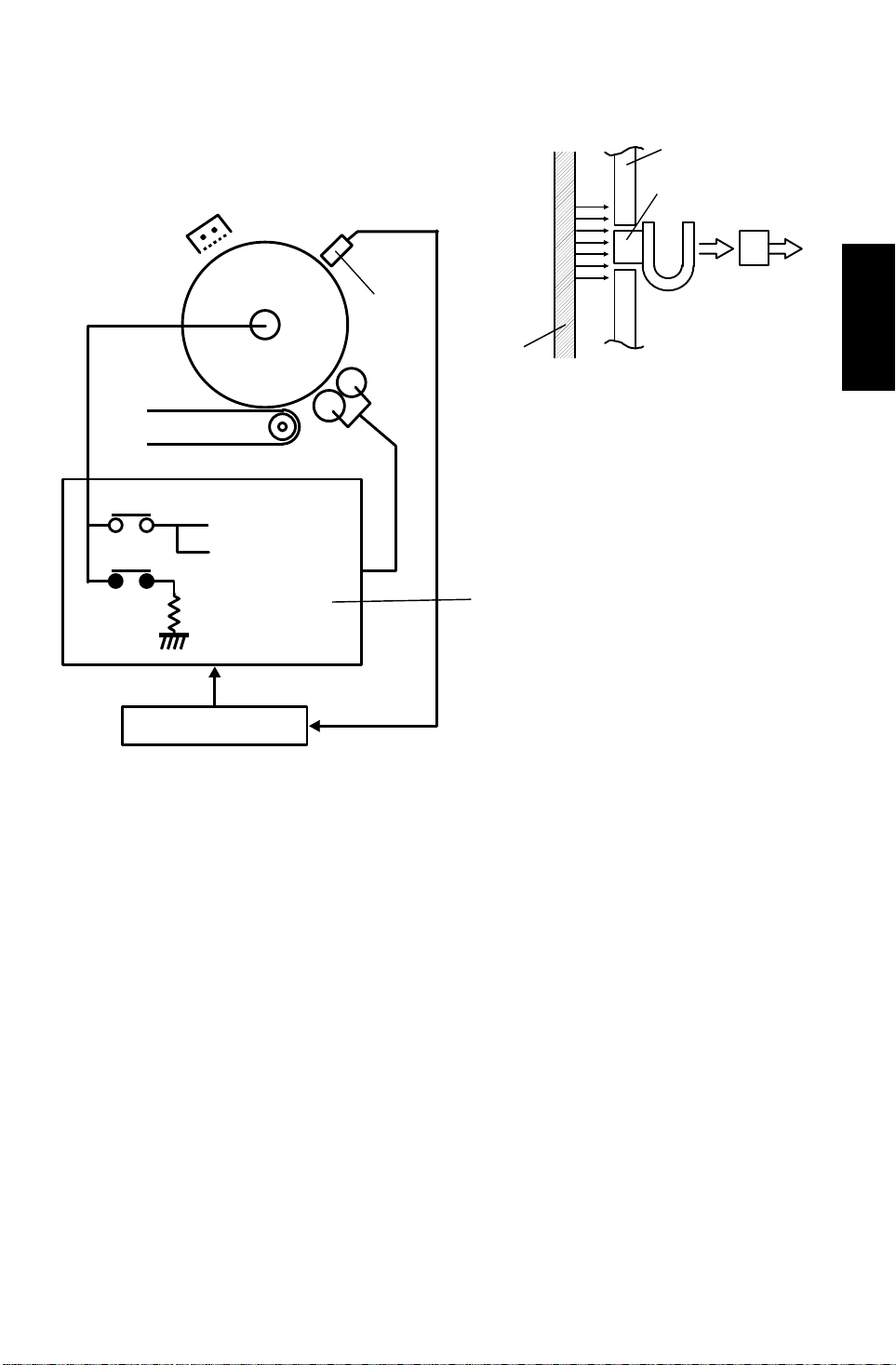
The exhaust fan [A] located above the fusin g un it pro vides an air flow to the
charge corona unit to pre vent uneven built-up of negat ive ions that can cause
an uneven charge of th e drum surface as shown.
An ozone filter [B] abso rbs the ozone (O3 ) around the drum.
The exhaust fan rotates slowly during stan d-b y and rota te s quickly during
copying to keep the temperature inside the machine constant.
2-21
Page 47

DRUM UNIT 23 April 1993
2.3.3 Charge Wire Cleaning Mechanism
[A]
[C]
[A]
[C]
[B]
The flow of air around the charge corona wire may deposit tone r part icles on
the corona wires. These particles may int erfere with charging and cause low
density bands on copies.
The wire cleaner pads [A] automa tica lly clean the wires to pre ven t such a
problem.
The wire cleaner is driven by a dc motor [B]. No rmally th e wire clea ne r [C] is
located at the front end position (home position). After 5000 or more copie s
are made and fusing temperature is less than 100°C after the main switch is
turned on, the wire cleaner motor turns on to bring the wire cleaner to the
rear end and then back to the home position.
When the wire cleaner moves from the rear to the home position (black arrow
in the illustration), the wire clean er pads clean the wires.
There are no home position and retu rn po sitio n sen sors. The CPU monitors
the input voltage (5 V). When the wire clean er rea che s the end, it is stop pe d
and the motor is locked. At this time, in put voltage slightly decreases (to
about 4 V) and the CPU judges to rotate the motor in reverse.
2-22
Page 48

23 April 1993 DRUM UNIT
2.4 ERASE
2.4.1 Overview
EL
LE
SE
Detailed
Descriptions
LOES
LC
LE: Lead edge erase marg in 3.5 ± 2.5 mm
SE: Side era se margin total of both sides 3 mm or less
Lo: Original width
Lc: Charged width of drum
EL: Lead edge erase
Es: Side erase
The erase lamp unit consist s of a line of 12 3 LE Ds extending across the full
width of the drum, the width of each bein g abou t 2. 5 mm. In edit ing mo de, th e
appropriate LED’s turn on acco rdin g to the custo mer’s de sign ation.
2-23
Page 49

DRUM UNIT 23 April 1993
2.4.2 Lead Edge and Trail Edge Erase
The entire line of LEDs turns on when the main mot or tu rns on . The y stay on
until the erase margin slight ly overla ps the lead edge of the original ima ge on
the drum (lead edge erase margin). It preve nts the shadow of the original
lead edge from appearing on the copy paper. This lead erase margin is also
necessary for the lead edge of the copy pape r to sep ara te from th e hot roller.
The width of the lead edg e era se marg in can be adjusted by SP mode
1
( SP Adjustment mode: PAGE 3).
When the scanner reache s the return position, the charg e coro na , the grid
bias, and the exposure la mp tu rn off. However, the charged area on the drum
surface is a little longer than the actu al orig ina l le ngth in order to have the
entire latent image of the original.
The entire line of LEDs turn on when the trail edge of the latent image has
passed under the erase la mp un it. This p reve nts developing unnece ssary
parts of the drum surfa ce, reducing toner consump tio n an d drum cleaning
load.
The LEDs stay on to erase th e lead edge of the laten t image in the next copy
cycle. After the fina l copy, the erase lamps turn off at the same time as the
main motor.
2.4.3 Side Erase
Based on the combinat ion of copy paper size and the reproduction ratio data,
the LEDs turn on in blocks. This prevent s the shad ow of the origin al side
edge and unexposed fro nt and rear sides of the drum surface in reduction
mode from being develop ed . This red uces toner consumption an d dru m
cleaning load.
In the DJF mode, the horizontal original standard position on the exposu re
glass is 5 mm away from the rear scale.
In the RDH mode, the horizontal center of the original is aligned with the
center of the exposure glass.
On the other hand, the horizontal origin al sta nd ard posit ion on the exposure
glass in the platen cove r mode is the rear scale edge.
To erase the shadow made by th e ed ge of th e rea r sca le in pla ten cover
mode, one more LED at the fron t side turns on. This is in addition to th e
LED’s on in DJF and RDH modes.
2-24
Page 50

23 April 1993 DRUM UNIT
2.5 CLEANING
2.5.1 Overview
[A]
[C]
[B]
[D]
Detailed
Descriptions
4 mm
This copier uses the counter blade system for drum cleaning.
The blade [A] is angled against drum rotation. This counter blade system has
the following advantages:
• Less wearing of the cleaning blade edge.
• High cleaning efficiency.
Due to the high efficiency of this cleaning system, the pre-cleaning corona
and cleaning bias are not used for this copier.
The cleaning brush [B ] is used to support the cleanin g bla de .
The brush collects toner from the dru m surface and scraped by the cleaning
blade. Toner on the cleaning brush is scraped off by th e mylar [C] and falls to
the toner collection coil [D]. Ton er is transported to the toner collectio n bottle
by the toner collection coil.
To remove the accumulated toner at the edge of the cleaning blade, the drum
turns in reverse for about 4 mm a t th e en d of every copy job. The
accumulated toner is removed by the cleaning brush by this action.
2-25
Page 51

DRUM UNIT 23 April 1993
2.5.2 Drive Mechanism
[C]
[E]
[A]
[B]
[D]
The drive force from the main motor is transmitted to the cleaning unit drive
gear via the timing belt [A] and the cleaning unit coupling [B]. The cleaning
unit drive gear [C] then transmits the force to th e fro nt side through the
cleaning brush [D]. The force at the front side is used for the toner collection
coil gear [E].
2-26
Page 52

23 April 1993 DRUM UNIT
2.5.3 Cleaning Blade Pressur e Mechanism and Side-to-Side Moveme nt
[C]
[A]
[D]
[B]
The spring [A] always push es the cleaning blade against the OPC drum. The
cleaning blade pressure can be manually released by pushing up the release
lever [B]. To prevent clean ing blade deformation durin g the transportation ,
the release lever is locked in the pre ssure release (upper) position .
The pin [C] at the rear end of the cleaning blade holder touches the cam gear
[D] which gives a side-to-side moveme nt to the blade. This movement helps
to disperse accumulated toner to prevent early blade edge deterioration.
Detailed
Descriptions
2-27
Page 53

[D]
DRUM UNIT 23 April 1993
2.5.4 Toner Collection Mechanism
[B]
[E]
[G]
[F]
[C]
[A]
Toner collected by the cleaning unit is transported to the toner collection
bottle [A] through the tone r collect ion tubes. Three helical coils are use d for
toner transport.
One coil [B] is driven by the main motor via drive belts and the other coil [C]
is driven by an independent toner collection drive motor [D].
The actuator disk [E] on the toner collection drive mot or mon ito rs the proper
rotation of the toner collectio n coil [C] to pre ven t th e coil fro m being damaged
by toner clogged in the colle ction tube. The main PCB monitors the sensor
output and increases t he mo to r sp ee d if th e sensor monitors that the to ne r
collection motor rotates at a speed lower th an norma l. Also , th e CPU will
display an SC 342 if no signal changes (ON → OFF) are detecte d for more
than 2.55 seconds while the toner collection motor is turning.
When the toner collection bottle [A] become full, the toner pressure in the
bottle increases and presses the gear [F] against the toner overflo w swit ch
[G]. After the toner ove rflo w switch is a ctiva te d, the finishing of the copy job,
or up to 100 continuou s copie s, is a llowed, then copying is prohib ite d an d the
service call "full toner collection bottle" indication is displayed on the LCD.
This condition can be cleared by de-a ctuating the toner overflo w switch while
de-actuating then actua tin g the to ner co llect ion bot tle swit ch ([C] in next
page).
2-28
Page 54

23 April 1993 DRUM UNIT
[B]
[C]
[A]
Detailed
Descriptions
2.5.5 Pick-off mechanism
The pick-off pawls are always in contact with the drum surface with weak
spring pressure. They move side to side during the copy cycle. This
movement is made via a shaft [A] and an ecce nt ric ca m [B] .
2.5.6 Toner Collection Bottle Set Detection
The toner collection bottle set switch [C] prohibits machine operation by
indicating SC343 wh ile th e toner collection bottle is not set .
2-29
Page 55

DRUM UNIT 23 April 1993
2.6 QUENCHING
[A]
In preparation for the ne xt cop y cycle , ligh t fro m t he que nch ing la mp (QL ) [A]
neutralizes any charge remaining on the drum.
The quenching lamp consist s o f a line of 16 LEDs extending across the full
width of the drum.
Yellow colored LEDs are used fo r Q L to reduce ultra violet light which would
cause light fatigue on the OPC drum.
2-30
Page 56

[D]
23 April 1993 OPTICS
3. OPTICS
3.1 OVERVIEW
[A]
[C]
[B]
[E]
Detailed
Descriptions
The optics unit reflects an image of the origin al on the expo sure glass onto
the OPC drum. This forms a latent electrical image of the origin al.
On this model a halogen lamp (85 V 23 0 W) is use d fo r t he expo sure la mp
[A]. Lamp surface is frosted to ensure even exposu re.
Six mirrors are used to make the optics unit smaller and obtain the wide
reproduction ratio ran ge (50 ~ 200 %).
The lens [B] is driven by two stepping motors for (1) vertica l direction (parallel
to the paper feed direction) an d (2) horizontal direction movement s.
To correct focal length change in reduction and enlargement modes, the third
scanner unit [C] (4th and 5th mirrors) posit ion is changed by a stepping motor.
The toner shielding filte r [ D] is gree n (a gree n filter partly absorbs red light)
to improve red original duplication.
The optic anti-condensation heate r [ E] (located on the optic base plate) turns
on while main switch is turned off to preve nt the moistu re from forming on the
optics.
2-31
Page 57

OPTICS 23 April 1993
3.2 SCANNER DRIVE
[A]
[C]
[B]
[D]
[E]
A dc servo motor is used as the scanner drive moto r [ A] . Sca nn er drive
speed is 330 mm/sec. during scanning, and 1950 mm/sec. whe n the scanner
goes back.
The scanner drive motor drives the first [B ] and second scanners [C] using
two scanner drive wires via the timing belt [D] and the scanner drive shaft [E].
The second scanner speed is half of the first scan ne r spee d.
The scanner drive wire is not directly wound around the pulley on the
scanner drive motor.
2-32
Page 58

23 April 1993 OPTICS
3.3 VERTICAL LENS DRIVE
[B]
[A]
Detailed
Descriptions
HP (100%)
ReduceEnlarge
(Enlarge → HP)
(Reduce → HP)
(Enlarge → Enlarge)
(Reduce → Reduce)
(Enlarge → Reduce)
(Reduce → Enlarge)
steps30 30 30 30
The lens vertical drive motor [A] changes the lens vertical position in
accordance with the selected re pro du ctio n rat io.
A stepping motor (approx. 0. 09 5 mm/st ep) is use d to drive th e len s thro ug h
the lens drive belt. The maximum lens vertica l shift dista nce is 290 mm (from
the position at 50% to the position at 200%).
The lens vertical home position sensor [B] detects the lens vertical position
for full size mode. The optic control PCB keep s track of the lens po sitio n
based on the number of pulse s sent to the lens vertical drive motor.
2-33
Page 59

OPTICS 23 April 1993
3.4 HORIZONTAL LENS DRIVE
[A]
40
steps
Enlarge
40
HP
Reduce
40
The original horizont al position on the exposure glass varies dependin g on
the mode (such as platen, DJF and RDH modes) for easy original handling .
However, the cente r is th e sta nd ard position for paper feed.
Therefore, the lens ho rizontal position has to be cha ng ed accord ing to paper
size, reproduction ratio, original feed modes an d th e ed it mod es (centering,
margin adjust, etc.).
A stepping motor (ap pro x. 0.07 mm/step) is used to drive the lens through the
lens drive belt.
The lens horizontal ho me position sensor [A] is used to dete ct the lens
horizontal position fo r A4/ LT side ways, in full size an d pla ten mode.
The other positions are determined by counting the number of moto r drive
pulses.
Since this model has a horizontal lens drive mechanism, side-to-side
registration adju stme nt for each feed station can be don e easily b y using SP
mode ( SP Adjustment mode: PAGE 4).
1
2-34
Page 60

23 April 1993 OPTICS
3.5 HORIZONTAL LENS POSITIONI N G
3.5.1 For Original Position
Platen
DJF
5
100%
[A]
[C]
143.5
RDH
(Center)
Horizontal
2.5
Lens Position
Copy Paper
[B]
There are three standard orig ina l positions for the platen, DJF and RDH
modes.
In platen mode, the original is align ed with both the rear [A ] an d the lef t [B]
original scales (rear left corner [C] is the standard position).
In RDH mode, the original position is the cen te r of th e left scale [B].
In DJF mode, the original position is 5 mm to front of the pla te n mod e original
position to maintain th e orig ina l t ran spo rt pa th (5 mm from the rear scale).
The above figure shows the le ns horizontal positions for each original mode
when identical size paper is used.
Detailed
Descriptions
3.5.2 For Paper Size
Original Rear Edge
Horizontal
100%
Lens Position
Copy Paper
To keep high paper feed performance, the center is assigned as the paper
feed standard position . The ref ore, the lens horizontal position is chan ged
according to the paper size.
The figure shows the lens horizont al po sitio n fo r each paper size in fu ll size
mode.
2-35
Page 61

Copy Paper
OPTICS 23 April 1993
3.5.3 For Reproduction Ratio
Original Rear Edge
100% 50%
Original
200%
100%
3rd Scanner Position
50%
200%
When the reproduction ratio is changed, the vertical position of the lens is
changed. At th e same time, the total focal len gt h ha s t o be chan ge d to adjust
the image focusing. For this focal length change , th e ho rizon tal position of the
3rd scanner is also adjusted. The maximu m 3rd mirror shif t distance is 50
mm (from the position at 100% to the position at 50, 200%).
The figure shows the lens horizont al po sitio n fo r 50, 100 and 200%.
2-36
Page 62

23 April 1993 OPTICS
3.6 3RD SCANNER DRIVE
[B]
[A]
(Initialize)
Detailed
Descriptions
(Reduce/Enlarge → HP)
(Reduce/Enlarge → Reduce/Enlarge)
(Reduce/Enlarge → Reduce/Enlarge)
(Reduce/Enlarge →Enlarge/Reduce)
40 steps 40 steps
To compensate the focus for reproduction and lens po sition changes, the 3rd
scanner (4th and 5th mirrors) position is changed.
A stepping motor [A ] (ap prox. 0.095 mm/step) is used fo r the 3rd scan ne r
drive.
The 3rd scanner home positio n sen sor [B] is used to detect the un it po sitio n
for full size mode. The optic control PCB keep s track of the unit posit ion
based on the number of motor drive pulses.
2-37
Page 63

Optic Thermistor
Scanner Drive
Horizontal Lens
Drive
Vertical Lens
Drive
3rd Scanner
Drive
Optic Cooling
Fan
OPTICS 23 April 1993
3.7 OPTICS CONTROL CIRCUIT
Main
Control
Board
Main
CPU
Sensors
Data
Bus
Optics Control Board
Optics Control
CPU
E
M
M
M
M
Encoder
M
Exposure Lamp
AC Drive
Board
The optic control board communicates with the main board through a data
bus. The optics control board mon ito rs all t he sensor signals, encoder output,
thermistor output and controls all motors in the opt ics.
At the programmed time, the main CPU sen ds a scan ne r start signal to the
optics control CPU.
The CPU generates a pulse-width modulation (PWM) signal. The PWM
signal goes to a driver circuit, which sen ds drive pulse s to th e scan ne r drive
motor.
An encoder in the scanner drive mot or ge nerates pulse signals.
A speed/direction contro l circu it mon ito rs t he sca nner speed and the direction
of the signals, and uses th is dat a to re gu lat e the motor speed.
The home position sensor mon itors the position of the scan ne r. Whe n the
main switch is turned on, the main CP U conf irms t he posit ion of the scanner
by moving the scanner out of the home posit ion and back ag ain . This da ta is
sent to the optics control CPU.
2-38
Page 64

23 April 1993 OPTICS
3.8 AUTOMATIC IMAGE DENSITY CONTROL SYSTEM (ADS)
[B]
[A]
Detailed
Descriptions
In ADS mode the original backgroun d densit y is sensed by the ADS sensor
[A] and the main CPU determines an appro pria te deve lopment bias voltage
for the original to preven t dirty backgrounds from appearing on copie s.
The ADS sensor board is moun te d on the rear side of the optics side plate.
The sensor board is covered by the sensor housing cover which has a small
hole to direct the reflected lig ht from th e orig ina l t o the ADS senso r.
The ADS sensor standard voltage is adjusted to 2.7 V when proce ss co nt rol
data initial setting is performed. The exposu re lamp turns on with ID level 4 at
the home position and the light refle cte d by th e ADS patte rn [B ] (white
painted) reache s the ADS sen sor. The main CPU adjusts the ADS gain dat a
automatically to make the out pu t 2. 7 V. This gain data is stored in the RAM
board.
2-39
Page 65

20 mm
OPTICS 23 April 1993
90 mm
9.7
A =
M
(mm)
M = 1.0 (m = 50 ~ 100)
m
M =
AB
B =
(m = 101 ~ 200)
100
8.25
x 100 (mm)
m
m: reproduction ratio
[V]
(50 ~ 200)
ADS
Sensor
Output
ADS
Original
Voltage
Peak hold
For the first scanning of an original in ADS mode, the CPU starts samplin g of
the ADS sensor output while exposing the ADS patte rn at the scann er ho me
position. Then the CPU stores th e maximu m ADS sen sor ou tp ut as a
reference voltage. This me ans tha t eve ry ADS check cycle, the first scanning
for the original, th e ADS re fe rence voltage is renewed by the la te st exposure
light reflected by the ADS pattern.
In the full size mode, th e CPU samp les the ADS sensor output whe n th e
scanner scans the original from 9.7 mm to 18 mm from th e left scale edge.
The CPU takes the maximum ADS sen sor ou tput during the sampling period
and compares it with the ADS refere nce voltage to determine the proper
development bias vo lta ge . (See development bias con tro l se ctio n for details.)
The sampling length of ADS senso r o ut pu t fo r t he original differs dependin g
on the reproduction ratio because the scanner speed is different.
2-40
Page 66

Darker
3
4
23 April 1993 OPTICS
3.9 MANUAL IMAGE DENSITY CONTROL
When the image density is set manually, th e volt ag e ap plie d to the expo sure
lamp changes as shown in the table below.
Dev. Bias
Voltage
(negative)
Exposure
Lamp Voltage
V
VBB –60
LAMP +4.5
V
V
LAMP +3.0
VLAMP +0.5
LAMP –1.5
V
LAMP –3.5
V
BB –90
VBB
V
LAMP
Lighter
Detailed
Descriptions
V
LAMP –5.5
6
7
5
21
VLAMP: Exposure lamp voltage at ID level 4.
This value is determined at process control data initial setting.
VBB: Development bias (negative) voltage at ID level 4.
This value is determined at process control data initial setting.
Manual ID
Position
2-41
Page 67

[D]
OPTICS 23 April 1993
3.10 UNEVEN LIGHT INTENSITY CORRECTION
[D]
original
[D]
exposure
intensity
illumination
Shading plate
[A] [B] [C]
distribution
[A] [B] [C]
The entire exposure lamp surface is frosted to ensu re eve n exposure.
To compensate for red uced light at the edge of the lens, a shading plate is
placed in front of the lens. The shading plate is fixed to th e lens unit.
The shading plate compensates the light intensity when the lens horizontal
position is shifted ([A] to [C]).
Also three shading mylars [D] int ercept any diffused refle cte d light from
outside the light path.
2-42
Page 68

23 April 1993 OPTICS
3.11 ORIGINAL SIZE DETECTION IN PLATEN MODE
[E]
[B]
[D]
[C]
Detailed
Descriptions
[A]
There are three reflective sensors (APS sensors) in the optics cavity for the
original size detection. Origin al widt h Se nso r [ A] is used fo r se nsin g th e
original width and Original Lengt h Sensor-1 [B] and Original Length Sensor-2
[C] sense the origina l leng th.
Inside each APS sensor, there is a n LED [D] an d th ree pho to ele ctric de vices
[E]. The light generated by the LED is broken up in three beams and each
beam scans a different point of the exp osu re gla ss. If the original or platen
cover is present over the scan ning point, the beam is refle cte d an d ea ch
reflected beam expose s a photo ele ctric de vice and act ivates it.
While the main switch is on, these sensors are active and the origin al size
data is always sent to the main CPU. Howeve r, the main CPU checks the
data only when the platen cover is opened.
2-43
Page 69

OPTICS 23 April 1993
[A]
Original Size Length Sensor 1 Length Sensor 2 Width Sensor
A4/A3 version LT/DLT version 1 2 3456789
A3 11 x 7 OOOOOOOOO
B4 10 x 14 XOOOOOOOO
—8
F4 8 x 13 XXOOOOOOX
A4–L 8
B5–L — X X X OOOOXX
A5–L 5
B6–L — X X X X O O X X X
A6–L — X XXXXOXXX
A4–S 11 x 8
B5–S — X X X X OOOOO
A5–S 8
A6–S — X XXXXXXXX
1/2 x 14 X O O – O – O O X
1/2 x 11 XXXOOOOOX
1/2 x 81/2 XXXOOOXXX
1/2 XXXOOOOOO
1/2 x 51/2 XXXXXOOXX
NOTE: –L: Lengthwise
–S: Sideways
Sensors #4 and #6 are not used fo r L T/DL T version machines.
The check is done when the platen position sensor [A] turns on. This is when
the platen is positioned about 15 cm above the expo sure glass. At th is time,
only the sensor(s) locate d unde rneath the original receive the reflected light
and are on. Other sensor(s) are off. Throu gh the on/ of f data of the nin e
(seven for LT/DLT version machine) sensors, the main CPU can reco gn ize
the original size.
In case the copy is made with the platen open, the main CPU decides the
original size only through the da ta when the Print key is pre ssed .
This original size detection method eliminat es the necessit y for a pre -scan
and increases the machine ’s prod uctivity.
2-44
Page 70

23 April 1993 DEVELOPMENT
4. DEVELOPMENT
4.1 OVERVIEW
[C]
[D]
[A]
This copier uses a double roller (diameter 20 mm each ) deve lop men t (DRD)
system. This system differs from single rolle r development systems in that (1)
it develops the image in a narrower area, (2) it develops the image twice, and
(3) the relative speed of each development roller against the drum is
reduced. Also, finer to ne r (App rox. 9 µ m) a nd deve loper (Approx. 70 µm) are
used. Both the DRD system and new sup plie s improve the image quality,
especially of thin horizontal line s, th e tra iling edg es of the half -to ne area s,
and black cross points.
[B]
Detailed
Descriptions
The paddle roller [A] picks up develope r in it s paddles and transports it to the
upper development roller [B ]. Int ern al pe rman en t mag ne ts in th e
development rollers att ract the deve lop er to the deve lop men t roller sleeve.
The upper development roller carries the developer past the doct or bla de [C].
The doctor blade trims th e de velo pe r to the desired thickness and creates
backspill to the cross mixing mechanism.
The development rollers con tin ue s to tu rn, carrying the deve lop er to the OPC
drum [D]. When the develo pe r b rush contacts the drum surface, the
negatively charged areas of the drum surface attract and hold the positively
charged toner. In th is wa y, th e latent image is develop ed .
The development roller is g iven a neg at ive bia s to prevent the toner form
being attracted to the non-imag e are as on the drum surf ace that may have a
slight residual negative charge.
After turning another 100 degrees, th e de velo pe r is ret urn ed to th e pa dd le
roller [A].
2-45
Page 71

DEVELOPMENT 23 April 1993
4.2 DRIVE MECHANISM
[C]
[D]
[E]
[A]
[B]
The gears of the develop ment unit are driven by the deve lop ment drive gear
[A] when the developmen t mot or [B ] (dc servomotor) turns.
The gears of the toner hopper are driven by the toner supply roller drive ge ar
[C] when the toner supply clu tch [D] act ivates.
The above gears are helical gears. Helical gears are more quiet than normal
gears. The teeth of the de velo pment drive gear are chamfered so that they
smoothly engage with th e de velo pment roller gear [E] when the unit is
installed.
2-46
Page 72
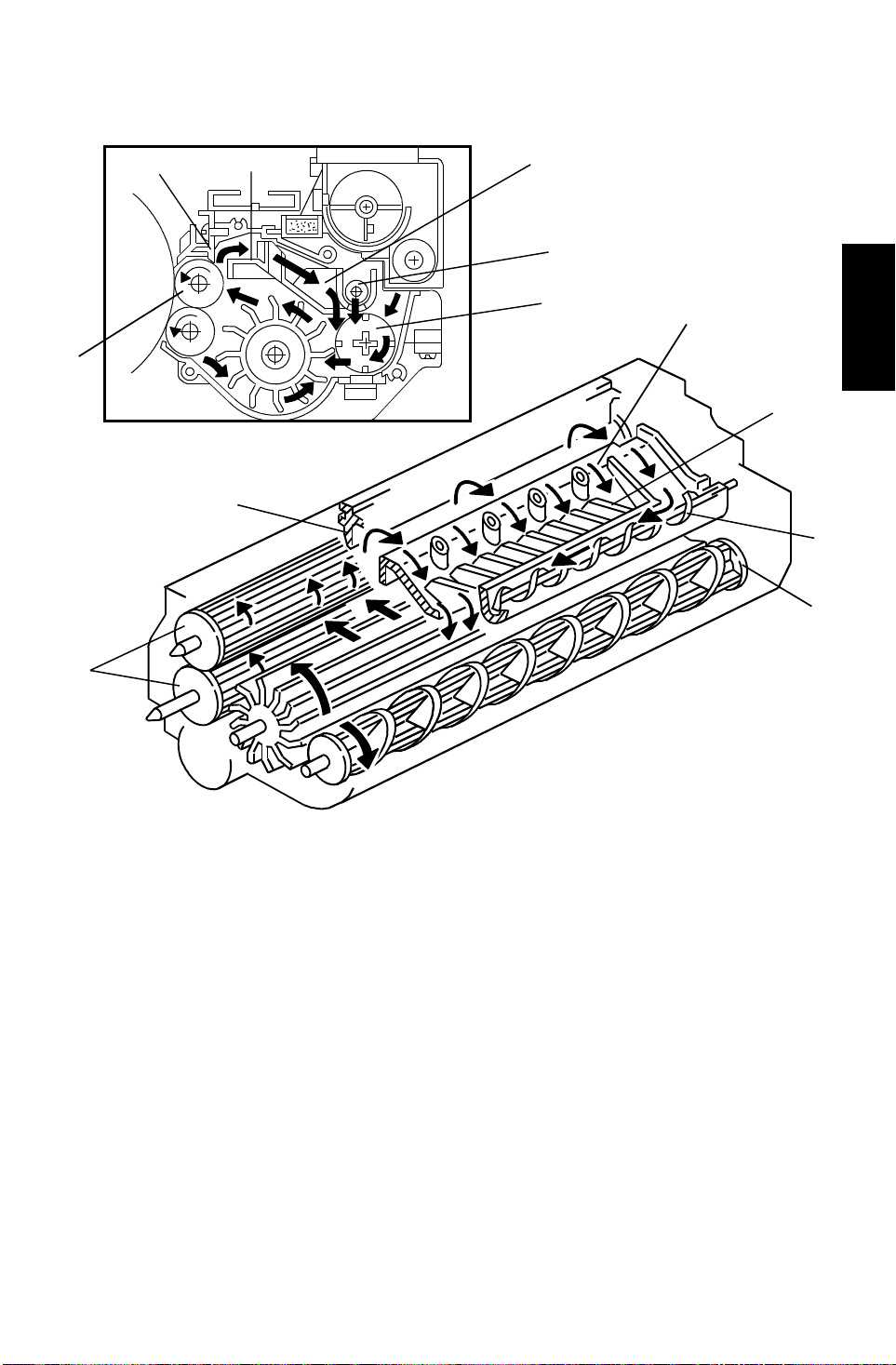
[C]
23 April 1993 DEVELOPMENT
4.3 CROSSMIXING
[A]
[A]
[B]
[B]
[C]
[E]
[F]
[D]
Detailed
Descriptions
[E]
[F]
[D]
This copier uses a standard cross-mixing mechanism to keep the toner and
developer evenly mixed . It also he lps ag ita te the developer to preve nt
developer clumps from forming and help s create the trib oelectric charge.
The developer on the tu rning development rollers [A ] is sp lit int o two parts by
the doctor blade [B]. The part tha t sta ys on th e de velo pme nt rollers forms the
magnetic brush an d develops the latent imag e on the drum. The part that is
trimmed off by the doctor blade goes to the backspill plate [C].
As the developer slides down the backspill plate to the agit ator [D], the mixing
vanes [E] move it slightly to ward the rear of the unit. Part of the deve loper
falls into the auger inlet and is transp ort ed to the fro nt of the unit by th e auge r
[F].
The agitator moves th e de velo pe r slig ht ly t o th e fro nt as it turns, so the
developer stays level in th e de velo pment unit.
2-47
Page 73

DEVELOPMENT 23 April 1993
4.4 DEVELOPMENT BIAS
4.4.1 Overview
[A]
[B]
[C]
The high voltage control Board [A] applie s the neg at ive de velo pment bias to
the lower sleeve roller through the receptacle [B] and the lower sleeve roller
shaft [C]. Then th e bia s is applied to the upper sleeve roller through the rear
sleeve roller holder made of condu ctive resin.
The development bias pre vents toner from being attracted to the background
area of the non-image area on the OPC drum where there is resid ual volta ge .
Also, the developmen t bias is used to adjust image de nsit y according to the
conditions the customer selected.
2-48
Page 74

Light
23 April 1993 DEVELOPMENT
4.4.2 Bias Control In Copy Cycle
The bias output is determined by five fa cto rs.
The total bias is described as;
ADS Mode: VB = VBB + VBU + VBMG + VBA
Manual ID Mode: VB = VBB + VBU + VBMG+ VBM
VB: Total bias
VBB: Base bias
VBA: ADS Compensation
VBU: User Tool mode ID Selection Compensat ion
VBMG: Magnification Compensation
VBM: Manual ID Selection Compensation
Detailed
Descriptions
1) Base Bias (VBB)
[V]
VD
V
BB
Drum
Potential
VL
VR
Dark
Original Density
As explained in the pro cess con trol section, the base bias fo r d eve lopment is
determined by the residual voltage (VR) measured in pro cess con tro l d ata
initial setting.
VBB = VR + (–220)
2) ADS Compensation (VBA)
VBA
(negative)
–300
1.02 V
0
122.7
1 2 2.3
Dark V
ADS (V) Light
According to the original background density, the bias is compensate d. Th e
compensation valu e is determined with the voltage measured by the ADS
sensor (ADS sensor outp ut : VADS) as follows:
VBA = 234 x (VADS –2.3)
NOTE: VBA has a limited range from 0 V to –300 V.
2-49
Page 75

Manual ID Position
2
DEVELOPMENT 23 April 1993
3) Manual ID Selection Position Compensation (VBM)
According to the manua l I D selection position, the bias is compensated as
follows:
Exposure
Lamp Voltage
V
V
V
V
V
V
V
Lighter Darker
LAMP+4.5
LAMP+3.0
LAMP+0.5
LAMP →
LAMP –1.5
LAMP –3.5
LAMP –5.5
BM
V
(negative)
–90
–60
0
7
56341
VLAMP: Exposure lamp voltage at ID level 4. This valu e is d et ermin ed at
process control data initial set tin g.
4) User Tool Mode ID Selection Compensation (VBU)
In the User Tool mode, the imag e de nsit y level can be selected from five
steps. The VBU is determined by the User Tool ID po sitio n setting as follows:
VBU
(negative)
Lighter Darker
–60
–30
54321
0
+30
+60
User Tool
ID Position
2-50
Page 76

142%
23 April 1993 DEVELOPMENT
5) Magnification Compensation (VBMG)
VBMG is determined by th e sele cted reproduction ratio as follows:
–100
Dev. Bias
Voltage
(negative)
–60
–40
–30
–20
50%
62%
81%
116%
115%80%61%
122%
123%
161%
141% 160%
4.4.3 Bias Control Out of Copy Cycle
To hold the toner on the sleeve rollers while the development sleeve rollers
are rotating with out image development, a constant –300 V bias is applied.
Detailed
Descriptions
2-51
Page 77

DEVELOPMENT 23 April 1993
4.4.4 ID Sensor Pattern Bias
–700 V
①
① Potential
Sensor Detection
VP
VP
③
② ID Sensor
Bias Le vel
4.0 V
VSG
③ ID Sensor Output
While developing the ID sen sor pa tt ern , ID sensor bias is applied. ID sensor
bias is determined during process control in itia l sett ing as follo ws:
A charge is applied while grid volta ge is –700 V to crea te the ID senso r
pattern.
–300
VSP
VIDB = VP +300 (V)
②
The drum potential (VP) of the ID sensor pattern is checked.
The ID sensor bias (VIDB) is adjusted so that it satisf ies th e followin g formula :
VIDB = VP – (–300)
= VP + 300 (V)
2-52
Page 78

[E]
[F]
23 April 1993 DEVELOPMENT
4.5 TONER SUPPLY
4.5.1 Toner Supply Mechanism
[A]
[B]
[B]
[F]
[C]
[D]
When the toner supply clut ch [A ] turns on, the agitator [B] moves the tone r
from front to rear and sends the toner to the toner supply roller.
The toner supply clutch [A] lo cat ed inside the deve lop men t motor [C] applies
the rotation from the deve lop men t mot or to the toner supply roller gear [D],
which drives the agitator ge ar [E]. Toner is caught in the grooves on the toner
supply roller [F]. Then, as the groo ves tu rn pa st the opening, the to ne r f alls
into the development unit.
Detailed
Descriptions
2-53
Page 79

DEVELOPMENT 23 April 1993
4.5.2 Toner End Detection
[A]
The toner end sensor [A] detects if sufficient toner remains in the toner
hopper or not. The ton er en d sen sor monitors toner end condition once when
the toner supply clutch turns on . Whe n th ere is little toner inside the toner
hopper and toner pressure on the toner end senso r b eco mes low, the toner
end sensor outputs a pulse signal for each (one detection per one copy).
The toner near end indication is displayed on the LCD after receiving the
pulse signal 150 times (If no pulse signal is out pu t twice cont inu ally, the pulse
count is canceled).
Fifty copies are allowed afte r ent ering toner near end condition. After fifty
copies are made in tone r nea r end cond ition, the machine enters the toner
end condition and copying is prohibited.
When the main switch is turned off and on, or th e fro nt doo r is opened and
closed, the machine drives to ne r supp ly mechanism and monitors the toner
end sensor output. If th e toner end sensor does not out pu t th e pu lse signal
twice continually, the toner end condition is canceled.
2-54
Page 80

23 April 1993 DEVELOPMENT
4.5.3 Toner Supply Control
By using an SP mode ( Adjustment mode: PA GE 7), the following 3 kind s
1
of toner supply controls can be sele cted.
• Auto Process Control Mode
• Detect Mode
• Fixed Mode
1) Auto Process Control Mode
Originals have various image proportio ns and imag e densit ies. For the
best toner supply control, it is necessary to link the amou nt of toner
supplied on each copy cycle to th e amo un t of ton e r con sumed for each
copy.
Fuzzy control is used in this model to pro vide this kind of toner supply
control.
Fuzzy Control 1
According to data of the ID se nso r and TD sen sor, the CPU ch ecks th e
following at every copy cycle:
1. The results of toner sup ply con trol (TD sensor output) in the
previous copy cycle.
Detailed
Descriptions
2. How quickly the toner density is changing.
Then the CPU decides the most suitable toner sup ply amo un t (toner
supply clutch on time) for the next copy cycle by using fuzzy logic.
2-55
Page 81

DEVELOPMENT 23 April 1993
Fuzzy Control 2
The image on the OPC drum changes due to variat ions in toner
chargeability (influence d by the en viron men t) even if toner
concentration is constant.
The ID sensor directly checks the image on the OPC dru m and shift s
the VREF data under fuzzy control to keep the image on the OPC drum
constant.
NOTE: The toner supply amount is changed at every copy cycle.
The target toner density sensor output is updat ed und er th e
following conditions:
1. During toner density sensor initial setting
2. During process control data initial setting
3. After the copy job is completed in case that 10 or more copies
have been made since the last update.
(Refer to section 2.1.4 "Ima ge Densit y Co nt rol" for de ta ils.)
2) Detect Mode
In this mode, only the TD sensor is used to con tro l t he ton er
concentration (VREF data is fixed). The machine pe rfo rms only fuzzy
control 1.
In ID sensor abnormal condition or Drum Pot en tia l se nso r abn orma l
condition, the machine au to matically enter this mode.
3) Fixed Mode
In this mode, a fixed amount of ton er is supp lied every cop y cycle as
1
determined (4%, 7%, 11%, 14%) by SP mode
( Adjustment mode:
PAGE 7). There is no overtoning detect ion mechanism.
In TD sensor abnormal condition, the machine automatically enters this
mode.
2-56
Page 82

23 April 1993 DEVELOPMENT
4.5.4 Bottle Drive Mechanism
[C]
[D]
[E]
[B]
For easy access, the toner bot tle is just inside the fron t cove r. The bot tle is
positioned horizontally.
Detailed
Descriptions
[A]
The bottle drive mechanism tra nsp orts toner from the bottle to the to ner
hopper [A]. A worm gear [B] on the bot tle drive mot or drive s t his mech an ism.
The toner bottle has a spiral groove [C] that helps move the toner to the tone r
hopper.
To prevent toner from sca tt ering when the toner bottle is removed from the
holder, toner shutter [D] which covers the hole [E] is installe d on the ton er
bottle.
When the toner is set on the hold er an d the lever is lowered, the toner shutter
[D] opens to supply toner t o th e to ne r h oppe r .
The bottle drive moto r turns on 0.7 seconds when the ton er en d sensor turns
on twice continually.
2-57
Page 83

IMAGE TRANSFER 23 April 1993
5. IMAGE TRANSFER
5.1 PRE-TRANSFER LAMP
[A]
The pre-transfer lamp [A] locat ed in the drum unit is used to pre vent
incomplete toner t ran sfer.
After the latent image is developed but bef ore the image is transferre d to the
copy paper, the drum surface is illuminated by the pre -tra nsf er lamp. This
illumination reduces the negat ive pote nt ial on the drum surf ace charged by
the main charge corona and partia lly d ischa rge d by th e exp osu re. Th is
makes image transfer easier.
The pre-transfer lamp is turne d on and off by the charg e power pa ck at the
same time as when the main motor turns on and off .
2-58
Page 84

23 April 1993 IMAGE TRANSFER
5.2 IMAGE TRANSFER AND PAPER SEPARATION
OVERVIEW
[E]
[F]
[A]
[D]
[B]
[C]
This model uses a unique transf er belt un it inst ea d of the tran sfer and
separation corona unit. The tra nsf er be lt un it con sists of the following parts:
[A] Transfer belt
A belt (length: 321 mm) with high electrical resistance which holds a high
negative electrical po tential and attracts the toner on the OPC drum onto
the paper. Also the electrical potential att racts the paper itself and helps
paper separation fro m the OPC dru m.
Detailed
Descriptions
[B] Transfer bias roller
Applies transfer voltage to the tran sfe r belt.
[C] Transfer belt lift leve r (driven by a solen oid)
Lifts the transfer belt to contact the tra nsfer belt with the OPC drum.
[D] Transfer power pack
Generates the constant transfer current.
[E] Transfer belt cleanin g bla de
Removes toner atta che d on the transfer belt to prevent the rear side of
the paper from being stained.
[F] Discharge plate
Helps paper separation from th e transfer belt by discharging the
remaining negative cha rge on the transfer belt.
2-59
Page 85

IMAGE TRANSFER 23 April 1993
5.3 IMAGE TRANSFER AND PAPER SEPARATION
MECHANISM
The registration rollers [A] start s
feeding th e pa per [B] to the gap
between the OPC drum [C] and
the transfer belt [D] in proper
timing.
Immediately when th e lea ding
edge of the paper reaches the gap
between the tra nsfer belt and
the OPC drum, the transf er belt
lift lever [E] raises the tra nsf er
belt to contact the
transfer belt and the OPC drum.
The lift lever is driven by a
solenoid
[D]
[C]
[E]
[A]
[A]
[B]
Then a negative transfer bias
–1.5 K ~ –2.0 KV is
applied to the transfer bias ro ller
[F] and attracts the positively
charged toner [G] on the OPC
drum. It also attracts the
paper and separate s the pap er
from the OPC drum.
–800 V
[F]
[G]
–1.3 K~ –1.8KV
–1.5 K ~ 2.0 KV
2-60
Page 86

23 April 1993 IMAGE TRANSFER
After the image tra nsf er is
completed, the charge on the
transfer belt holds the paper to
the transfer belt.
Before separating the paper from
the transfer belt, the transfer belt
is discharged by the discharge
plate [A].
The transfer power pack [B] inside
the transfer belt unit monitors
the current fed back from the
discharge plate to adjust the
transfer current. This way,
the current stays const ant even if
the paper, environmental
conditions, and the transfer belt
surface resistance are change d.
[A]
[A]
[B]
Detailed
Descriptions
[B]
2-61
Page 87

IMAGE TRANSFER 23 April 1993
5.4 TRANSFER BELT UNIT LIFT MECHANISM
[E]
[C]
[E]
[A]
[B]
[F]
[D]
The transfer belt lift solenoid [A] located inside the transfer belt unit turns on
to raise the transfer belt to con ta ct th e OPC d rum at the appropriate timing.
The front lever [B] and the rear lever [C] are connected to the solenoid by
links [D] and push up the stays [E ] whe n the solenoid turns on.
The support spring [F] helps the solenoid to raise the tr an sfer belt.
The solenoid turns off after the copy job is finished.
The transfer belt must be released from t he OPC dru m for th e followin g
reasons:
1. To prevent the ID sensor pattern on the OPC drum from being rubbed by
the transfer belt because the transfer belt is located between the
development unit an d th e ID sensor.
2. To decrease the load to the transfer be lt clea ning blade, it is better to
keep toner on the non-image area (fo r example VD, VL, ID sensor pattern
developed during process control data initial setting) from being
transferred onto th e transfer belt.
3. To prevent change of OPC drum characteristics by the influence of
additives inside the rubber belt.
2-62
Page 88

[E]
23 April 1993 IMAGE TRANSFER
5.5 PAPER TRANSPORTATION AND BELT DRIVE
MECHANISM
[C]
[A]
[E]
[F]
[B]
[F]
[D]
[D]
The transfer belt is driven by the ma in drive moto r [ A] thro ug h belt an d gears.
Since the transfer belt elect rically attracts the paper [B], the transport fan is
not required.
Detailed
Descriptions
The charge on the transfer belt is discharged by the discharge plate to
reduce paper attraction and paper is separated by the paper stiffness above
the transfer belt drive roller [ C] whe re th e tra nsf er be lt is turn ing.
The tapered parts [D] at both sides of the roller [ E] help ke ep the transfer belt
[F] at the center position.
2-63
Page 89

IMAGE TRANSFER 23 April 1993
5.6 TRANSFER BELT CLEANING MECHANISM
[D]
[A]
[B]
[C]
Some toner may adhere to transfer belt when paper jams occur, or whe n the
by-pass feed table side fences are set in the wrong position causing the
erase lamp to miss some toner. The adhe red ton er must be remo ved to
prevent the rear side of th e copy paper from being sta ined.
The cleaning blade [A] scrapes off any toner re main ing on the transfer belt.
A counter blade system is used for the transfer belt cleaning. The surface of
the transfer belt is coa te d to make it smooth and so preve nt the clean ing
blade from being flip pe d by th e transfer belt.
The lever [B] on the fro nt end of the cleaning blade releases the cleaning
blade when the tra nsf er be lt un it is lowered and the lever is pushe d by th e
transfer belt unit support prop. (The transfer belt unit is lowered when the
lever [C] is turned anti-clockwise)
When the cleaning blad e is released, the edge of the cleaning blade rubs the
seal so that the seal [D] remove s t he tone r or pape r d ust on th e cleaning
blade edge .
2-64
Page 90

23 April 1993 IMAGE TRANSFER
5.7 TONER COLLECTION MECHANISM
[B]
[A]
Detailed
Descriptions
Through idle gears [A], transfer belt drive is transmitted to the toner collection
coil [B]. The toner collectio n coil tra nsp ort s t he collected toner to the toner
collection bottle. Se e section 2.2.5 for details.
2-65
Page 91

PAPER FEED 23 April 1993
6. PAPER FEED
6.1 OVERVIEW
[A]
[B]
[A]
[B]
[C]
This model has three drawer tray pa per f eed sta tions.
The following table shows the configuration of each feed stations of the A095
and A096 copiers.
Feed station A095 copier A096 copier
1st 550 sheets tray 500 + 500 sheets tandem feed tray
2nd 550 sheets universal tray 550 sheets universal tray
3rd 550 sheets tray 1500 sheets built-in LCT
Paper can also be fed using the by-pass fee d ta ble which ha s an
independent feed mechanism. The by-pass feed table can hold 50 sheets of
paper.
All feed stations use an FRR feed system. Rotation of the pick-u p roller [ A]
drives the top sheets of paper from each tray to the feed [B] and the
separation [C] rollers. The feed an d separation rollers then take over paper
drive. If more than one sheet is fed by the pick-up roller, the separa tio n rollers
rotates in the opposit e direction and prevents all but the top sheet from
passing through to th e registration rollers.
2-66
Page 92

23 April 1993 PAPER FEED
6.2 FRR FEED SYSTEM
[B]
[A]
Detailed
Descriptions
[C]
This copier uses an FRR paper feed system using thre e rollers.
6.2.1 Pick-up Roller
The pick-up roller [A] is not in contact with the paper sta ck bef ore it starts
feeding paper. Short ly a ft er the Start key is pressed, the pick-up roller drops
down and feeds the top sheet betwee n the feed [B] and the separation rollers
[C]. At almost the same time th at the paper’s leading edge arrives at the feed
roller, the pick-up roller lifts off the paper stack so that it does no t int erf ere
with the operation of the feed and sep ara tio n rolle rs. The feed and separation
rollers then take over the paper feed pro cess.
6.2.2 Feed and Separation Rollers
There is a one-way bearing inside the fee d rolle r so it can tu rn on ly in one
direction. The separat ion roller is driven in the opposite direction to the feed
roller. The separatio n rolle r, ho weve r, is driven through a slip clutch (torqu e
limiter clutch) which allows it to turn in either directio n depe nding on the
friction between the rollers. The sep ara tion roller solenoid keeps the
separation roller in conta ct with the feed rolle r.
2-67
Page 93

F2F3F3
F1
PAPER FEED 23 April 1993
F2
F2
F1
[B]
F1
[B]
F1
[A]
[A]
The direction in which the separat ion roller [A] turns depends on the frictional
forces acting on it. The slip clutch applies a constant clockwise fo rce (F1).
When there is a single sheet of paper being driven between the rollers, the
force of friction betwee n the feed roller [B] and the paper (F2) is greater than
F1. So, the separation rolle r turns counterclockwise.
If two or more sheets are fed betwe en the rollers, the forwa rd fo rce on the
second sheet (F3), be come s le ss tha n F1 because the friction between the
two sheets is small. So, the separation roller sta rts tu rnin g clockwise and
drives the second sheet back t o th e tra y.
2-68
Page 94

[C]
23 April 1993 PAPER FEED
6.3 SLIP CLUTCH MECHANISM
[A]
Detailed
Descriptions
[G]
[D]
[F]
[B]
[E]
The slip clutch [A] consists of the inpu t hub [B ] an d the outp ut hub [C] which
is the case of the clutch as well. The mag ne tic ring [D] and the steel spa cers
[E] are fitted onto the input hub. The ferrite ring [F] is fitted int o the output
hub. Ferrite powder [G] packe d between the magnetic ring and th e fe rrite ring
[F] generates a consta nt torque due to magnetic force. The input hub and the
output hub slip when the rotational force exceeds the constant torque.
This type of slip clutch does not require lubrication.
2-69
Page 95

[J]
[F]
[I]
PAPER FEED 23 April 1993
6.4 FRR FEED DRIVE MECHANISM
[D]
[B]
[K]
[B]
[L]
[D]
[G]
[C]
[A]
[E]
[H]
The rotation of the paper feed mot or [A ] is t ran smitt ed to the gear [B] via the
timing belt [C], and then transmitted to the separation roller via the feed
clutch gear [D], gear [E], gear [F] and gear [G].
If the paper feed station is not select ed , th e sep ara tio n rolle r so len oid [H]
de-activates and the separation roller [I] rotates freely in the reverse direction
of paper f ee ding.
Gear [B] also transmits the drive to the vertical tran spo rt rolle r [ J] via gear [D] ,
idle gear [K] and gear [L ].
2-70
Page 96

[E]
23 April 1993 PAPER FEED
[A]
[F]
[D]
[C]
[B]
[I]
[G]
[H]
When the paper feed station is selected and the start key is pressed, the feed
clutch [A], separa tio n roller solenoid [B], an d th e pick-up solenoid [C] turn on
at once.
When the feed clutch [A] activates to rotate the feed roller [D], the feed roller
and the pick-up roller [E] turn togeth er be cau se th ey are linked by the idle
gear [F].
Detailed
Descriptions
When the separation roller sole no id [B ] tu rns on , th e separation roller [G]
contacts the feed roller [D] then rotates tog ethe r with the feed roller in spit e of
the separation roller’s drive in the opposite dire ctio n due to the torq ue limit er
function in the separatio n rolle r [G] .
When the pick-up solenoid [C] act ivat es, the pick-up roller [E] lowers to make
contact with th e to p sheet of the paper stack and send it to the feed an d
separation rollers.
When the paper feed senso r [ H] de te cts the leading edge of the paper [I], the
pick-up solenoid de-energizes to lift the pick-up roller and the paper f eed
clutch de-energizes at a certain time to wait until it is re ady to feed to the
registration roller.
2-71
Page 97

PAPER FEED 23 April 1993
6.5 SEPARATION ROLLER RELEASE MECHANISM
[B]
[A]
[C]
In this model, the separation roller [A] is normally awa y from th e feed roller
[B]. When the paper feed statio n is select ed , th e sep ara tio n rolle r so len oid [C]
contacts the separation roller to the feed roller as explained in the previou s
two pages.
This contact/relea se mechanism has the followin g three advantages:
1. When the paper feed motor turns on, all separation rollers in each fe ed
stations rotate. If the separat ion roller is away from the feed roller, it
reduces the mechanical loa d to the paper feed moto r and drive
mechanism, and also reduces we ar of the rubb er surf ace of th e
separation roller due to the frictio n between the separation roller and th e
feed roller.
2. After paper feeding is completed, paper sometimes remains in the gap
between the feed roller and the separation roller.
If the feed tray is drawn out in this con dition, it is possible for the
remaining paper to be torn.
When the separation roller is away from the feed rolle r, rema inin g paper
is released from the gap between th e feed and the sepa rat ion rollers.
3. When paper misfeeds occur around this area , the customer can easily
pull out the jammed paper between the fe ed and the sepa rat ion ro llers
because the separation roller is a way fro m the feed rolle r.
2-72
Page 98

[D]
[C]
23 April 1993 PAPER FEED
6.6 PAPER RETURN MECHANISM
[A]
[E]
[C]
[B]
[F]
[C]
3 mm
When the paper feed clutch [A] activates and the feed roller drive shaft [B]
rotates, the leve r [ C] rot at es together with the shaft. However, the lever is
immediately stopped by the stopp er [D] .
Detailed
Descriptions
After all paper is fed and th e pa pe r fee d clut ch turns off, the paper feed motor
still rotates to turn the separa tio n rolle r [E] in the reverse direction. The
separation roller, still contact ing the fee d roller, tu rns the feed roller in th e
reverse direction un til the lever hits the rubber cushion [F].
By this feed roller reverse mechanism, the paper remaining in the gap
between the feed and the separation rollers return s 3mm to the paper f eed
tray.
After that, th e sep aration roller solenoid turns off to move the separat ion ro ller
away from the feed roller. This releases the leading edge of the paper and
drops the paper to the paper feed tray.
This prevents remaining paper from being to rn when the feed tray is drawn
out.
2-73
Page 99
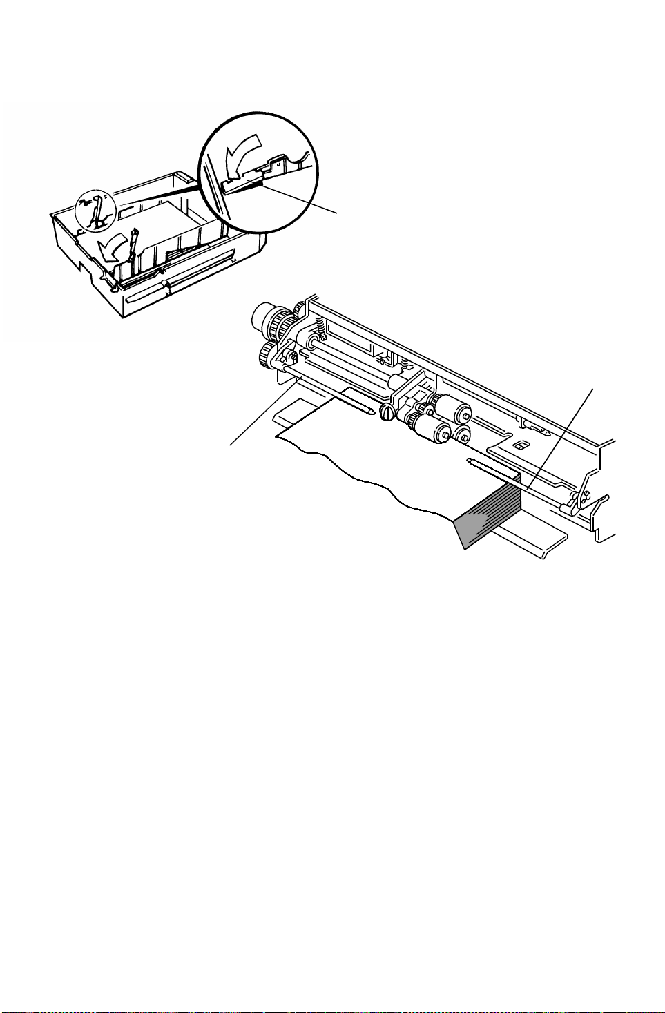
PAPER FEED 23 April 1993
6.7 PAPER SKEW PREVENTION MECHANIS M
[A]
[B]
[B]
In this model, paper corner hold ers [A ] are not used to facilita te pap er loa din g.
Instead of the corner hold ers, both pa per press arms [B] press down both
paper side edges, especially in the case of paper with a face curl. This helps
to keep paper from being guid ed by the tray side fen ces to prevent paper
skew or jam.
2-74
Page 100

[A]
[D]
23 April 1993 PAPER FEED
6.8 PAPER LIFT MECHANISM
[B]
[C]
[F]
[E]
When the tray is set in the machine, the machine detects this condition by
using several detection methods as shown in the table:
Detailed
Descriptions
Feed station A095 copier A096 copier
1st Tray set switch Tray set signal through the connector
2nd Paper size switch Paper size switch
3rd Tray set switch LCT set signal through the connector
When the machine dete cts th at the paper tray is set in the machine, the lift
motor [A] rotates and the coupling gear [ B] on th e tray lift motor engages the
pin [C] of the lift arm shaft [D], then turns the tray lift arm [E] to lift the tray
bottom plate [F].
2-75
 Loading...