

Ricoh FT 5640 Service Manual

IMPORTANT SAFETY NOTICES
PREVENTION OF PHYSICAL INJURY
1. Before disassembling or assembling parts of the copier and peripherals,
make sure that the copier power cord is unplugged.
2. The wall outlet should be near the copier and easily accessible.
3. Note that some components of the copier and the paper tray unit are
supplied with electrical voltage even if the main switch is turned off.
4. If any adjustment or operation check has to be made with exterior
covers off or open while the main switch is turned on, keep hands away
from electrified or mechanically driven components.
5. If the start key is pressed before the copier completes the warm-up
period, keep hands away from the mechanical and the electrical
components as the copier starts making copies as soon as the warm-up
period is completed.
6. The inside and the metal parts of the fusing unit become extremely hot
while the copier is operating. Be careful to avoid touching those
components with your bare hands.
HEALTH SAFETY CONDITIONS
1. Toner and developer are non-toxic, but if you get either of them in your
eyes by accident, it may cause temporary eye discomfort. Try to remove
with eye drops or flush with water as first aid. If unsuccessful, get
medical attention.
OBSERVANCE OF ELECTRICAL SAFETY STANDARDS
1. The copier and its peripherals must be installed and maintained by a
customer service representative who has completed the training course
on those models.
2. The RAM board on the main control board has a lithium battery which
can explode if replaced incorrectly. Replace the battery only with an
identical one. The manufacturer recommends replacing the entire RAM
board. Do not recharge or burn this battery. Used batteries must be
handled in accordance with local regulations.

SAFETY AND ECOLOGICAL NOTES FOR DISPOSAL
1. Do not incinerate the toner bottle or the used toner. Toner dust may
ignite suddenly when exposed to open flame.
2. Dispose of used toner, developer, and organic photoconductor
according to local regulations. (These are non-toxic supplies.)
3. Dispose of replaced parts in accordance with local regulations.
4. When keeping used lithium batteries in order to dispose of them later,
do not put more than 100 batteries per sealed box. Storing larger
numbers or not sealing them apart may lead to chemical reactions and
heat build-up.

A204/A206/A207/A208/A210/A211
COPIER
SERVICE MANUAL
The A204 copier is based on the A153 copier.
The A206 copier is based on the A155 copier.
The A207 copier is based on the A156 copier.
The A208 copier is based on the A157 copier.
The A210 copier is based on the A159 copier.
The A211 copier is based on the A160 copier.
Only the differences from the base copiers are described in the
following pages. Therefore, this documentation should be treated
as an insert version of the base copier’s service manual, although
it has a separate binder. It should always be utilized together with
the base copier’s service manual.

31 March 1997 SPECIFICATIONS
1. SPECIFICATIONS
NOTE:
Only items marked with ✽ are different from A153, A155, A156,
A157, A159, and A160 copiers.
Configuration: Desktop
Copy Process: Dry electrostatic transfer system
Originals: Sheet/Book
Original Size: Maximum: A3/11" x 17"
Copy Paper Size: Maximum: A3/11" x17" (Paper trays)
Minimum: A5/8
A4/11" x 8
A6/5
1/2
1/2
" x 5
" x 8
1/2
" sideways (Paper trays)
1/2
" sideways (LCT)
1/2
" lengthwise (By-pass)
Duplex Copying: Maximum: A3/11" x 17"
Minimum: A5/8
1/2
✽ Copy Paper Weight: Paper tray: 52 ~ 128 g/m
By-pass: 52 ~ 157 g/m
LCT: 52 ~ 128 g/m
Duplex copying: 64 ~ 105 g/m
" x 5
1/2
" (sideways)
2
, 14 ~ 34 lb
2
, 14 ~ 42 lb
2
, 14 ~ 34 lb
2
, 17 ~ 24 lb
Copier
Reproduction Ratios: 4 Enlargement and 6 Reduction
A4/A3 Version LT/DLT Version
200%
Enlargement
Full size 100% 100%
Reduction
141%
122%
115%
93%
82%
75%
71%
65%
50%
200%
155%
129%
121%
93%
85%
77%
74%
65%
50%
1

SPECIFICATIONS 31 March 1997
Power Source: 120 V/60 Hz:
More than 12 A (for North America)
220 V ~ 240 V/50 Hz:
More than 7 A (for Europe)
220 V/50 Hz:
More than 7 A (for Asia)
110 V/60 Hz:
More than 13 A (for Taiwan)
220 V/60 Hz:
More than 7 A (for Saudi Arabia, Philippines)
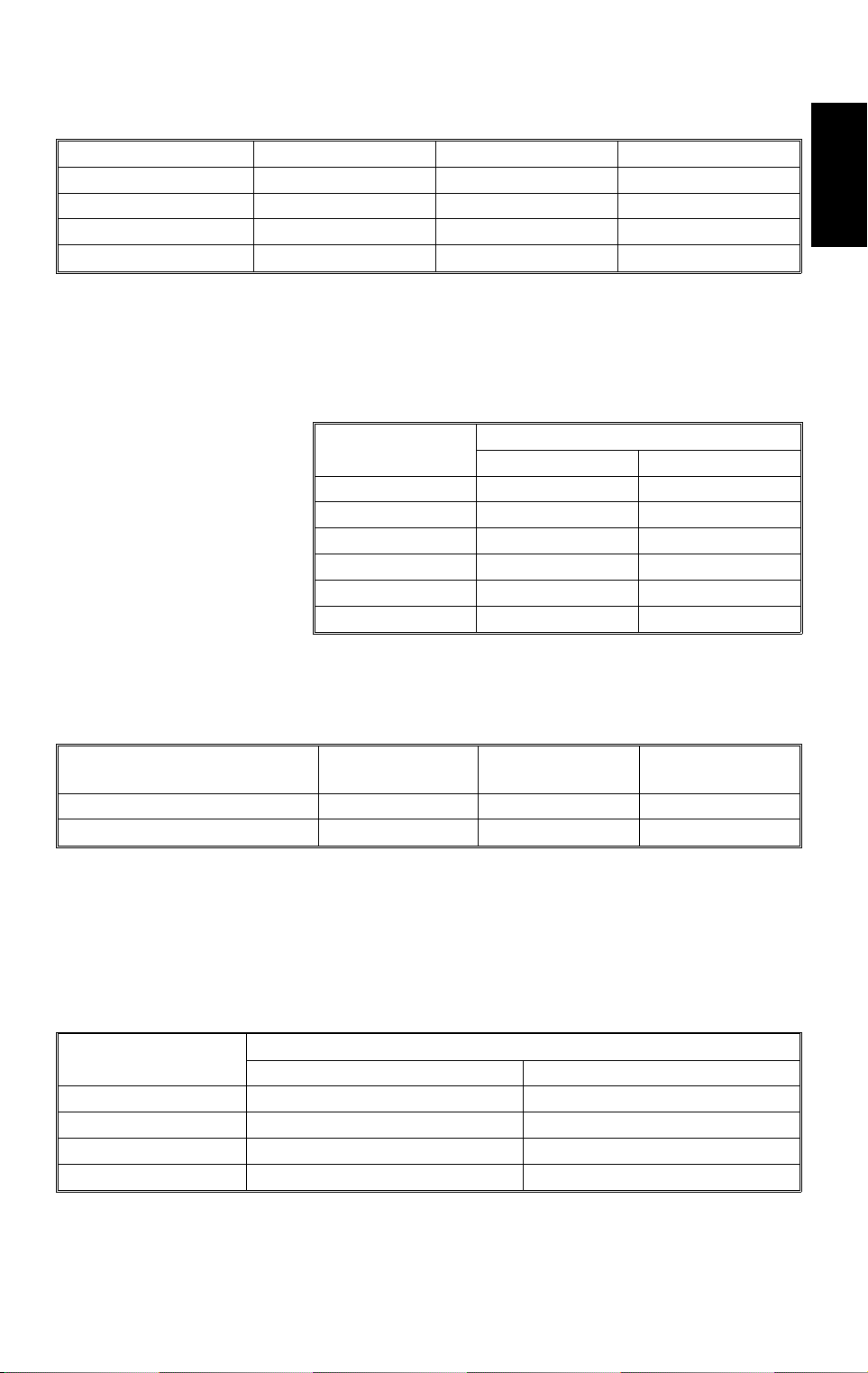
✽ Power Consumption:
A204, A206, and A2 07 copiers A208, A210, and A21 1 copiers
Copier Only Full System Copier Only Full System
Maximum 1.35 kW 1.40 kW 1.35 kW 1.40 kW
Copying 1.15 kW 1.21 kW 0.90 kW 1.00 kW
Warm-up 1.21 kW 1.23 kW 0.98 kW 1.00 kW
Stand-by 0.18 kW 0.20 kW 0.16 kW 0.18 kW
NOTE:
– Full System –
Copier + ARDF (A663) + Paper Tray Unit (A549) + 20 Bin S/S (A664)
✽ Noise Emission:
A204, A206, and A20 7 copiers A208, A210, and A211 copiers
Copier Only Copier Only
1. Sound Pressure Level
Operator position 64 dB (A) 63 dB (A)
Standard positio n 59 dB (A) 58 dB (A)
2. Sound Power Level
Copying 70 dB (A) 69 dB (A)
Stand-by 42 dB (A) 43 dB (A)
NOTE:
The above measurements were made in accordance with ISO 7779.
2
31 March 1997 SPECIFICATIONS
Dimensions:
Width Depth Height
A204 copier 1,030 mm (40.6") 655 mm (25.8 ") 606 mm (23.9")
A208 copier 900 mm (35. 5") 655 mm (25.8") 606 mm (2 3.9")
A206 and A207 copiers 1,258 mm (49 .6 ") 655 mm (25.8") 606 mm (2 3.9")
A210 and A211 copiers 1,128 mm (44 .5 ") 655 mm (25.8") 606 mm (2 3.9")
Measurement Conditions
1) With by-pass feed table closed
2) With platen cover and copy tray attached
3) With LCT cover closed
Copier
✽ Weight:
NA EU
A204 copier 70 kg (154.3 lb) 73 kg (160.9 lb)
A206 copier 78 kg (172.0 lb) 81 kg (178.5 lb)
A207 copier 81 kg (178.6 lb) 84 kg (185.2 lb)
A208 copier 69 kg (152.1 lb) 72 kg (158.7 lb)
A210 copier 77 kg (169.8 lb) 80 kg (176.4 lb)
A211 copier 79 kg (174.2 lb) 82 kg (180.7 lb)
Weight
Zoom: From 50% to 200% in 1% steps
✽ Copying Speed (copies/minute):
A4 sideways/
11" x 8
A204, A206, and A207 copiers 40 22/21 25
A208, A210, and A211 copiers 32 17/16 19
1/2
"
A3/11" x 17" B4/8
✽ Warm-up Time: A204, A206, and A207 copiers:
Less than 250 seconds (20°C)
A208, A210, and A211 copiers:
Less than 110 seconds (20°C)
" x 14"
1/2
✽ First Copy Time:
Paper Feed Station
1st Tray 4.4 s (except for A20 7) 4.9 s (except for A211)
2nd Tray 4.9 s 5.4 s
By-pass 4.4 s 4.7 s
LCT 4.4 s 4.9 s
NOTE:
In A207 and A211 copiers, the 2nd tray in the above table is called
the 1st tray.
A4/11" x 8
A204, A206, and A20 7 copiers A208, A210, and A211 c opi er s
3
" (sideways)
1/2

SPECIFICATIONS 31 March 1997
Copy Number Input: Ten-key pad, 1 to 999 (count up or count down)
Manual Image Density
7 steps
Selection:
Automatic Reset: 1 minute is the standard setting; it can be changed
to a maximum of 999 seconds or no auto reset by
SP mode.
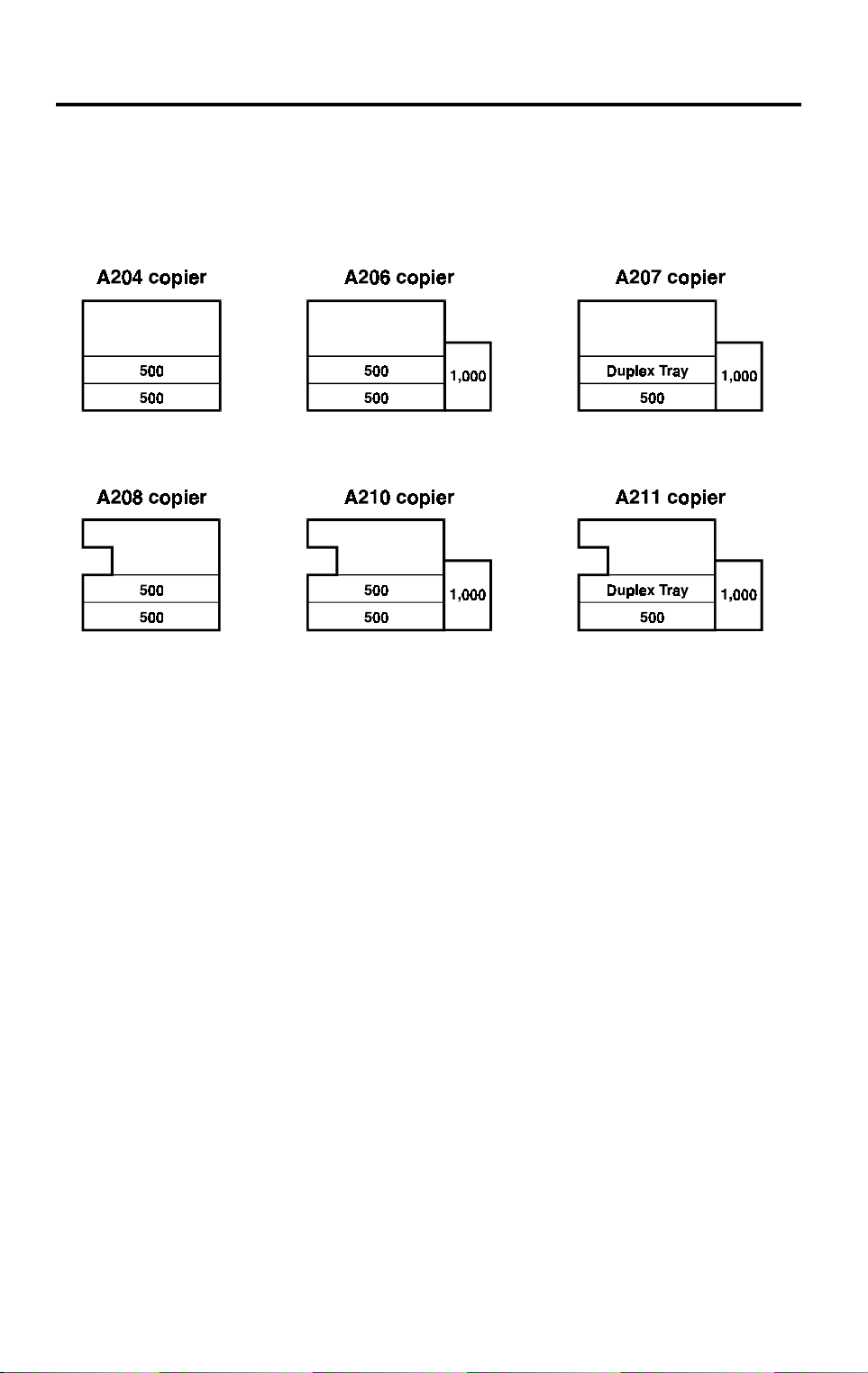
✽ Copy Paper Capacity:
Paper Tray By-pass Feed LCT
A204 copier About 500 sheets x 2 About 40 sheets —
A206 copier About 500 sheets x 2 About 40 sheets About 1,000 sheet s
A207 copier About 500 sheets x 1 About 40 sheets About 1,000 sheet s
A208 copier About 500 sheets x 2 About 40 sheets —
A210 copier About 500 sheets x 2 About 40 sheets About 1,000 sheet s
A211 copier About 500 sheets x 1 About 40 sheets About 1,000 sheet s
NOTE:
Paper tray - 500 sheets or less than 53 mm stack height
By-pass feed - 40 sheets or less than 4 mm stack height
LCT - 1,000 sheets or less than 120 mm stack height
Duplex Tray Capacity
[A207/A211]:
50 sheets (30 sheets for A3/11"x17"
81 ~ 105g/m
2
, 21.5 ~ 27.9 lb paper)
Toner Replenishment: Cartridge exchange (415 g/cartridge)
•
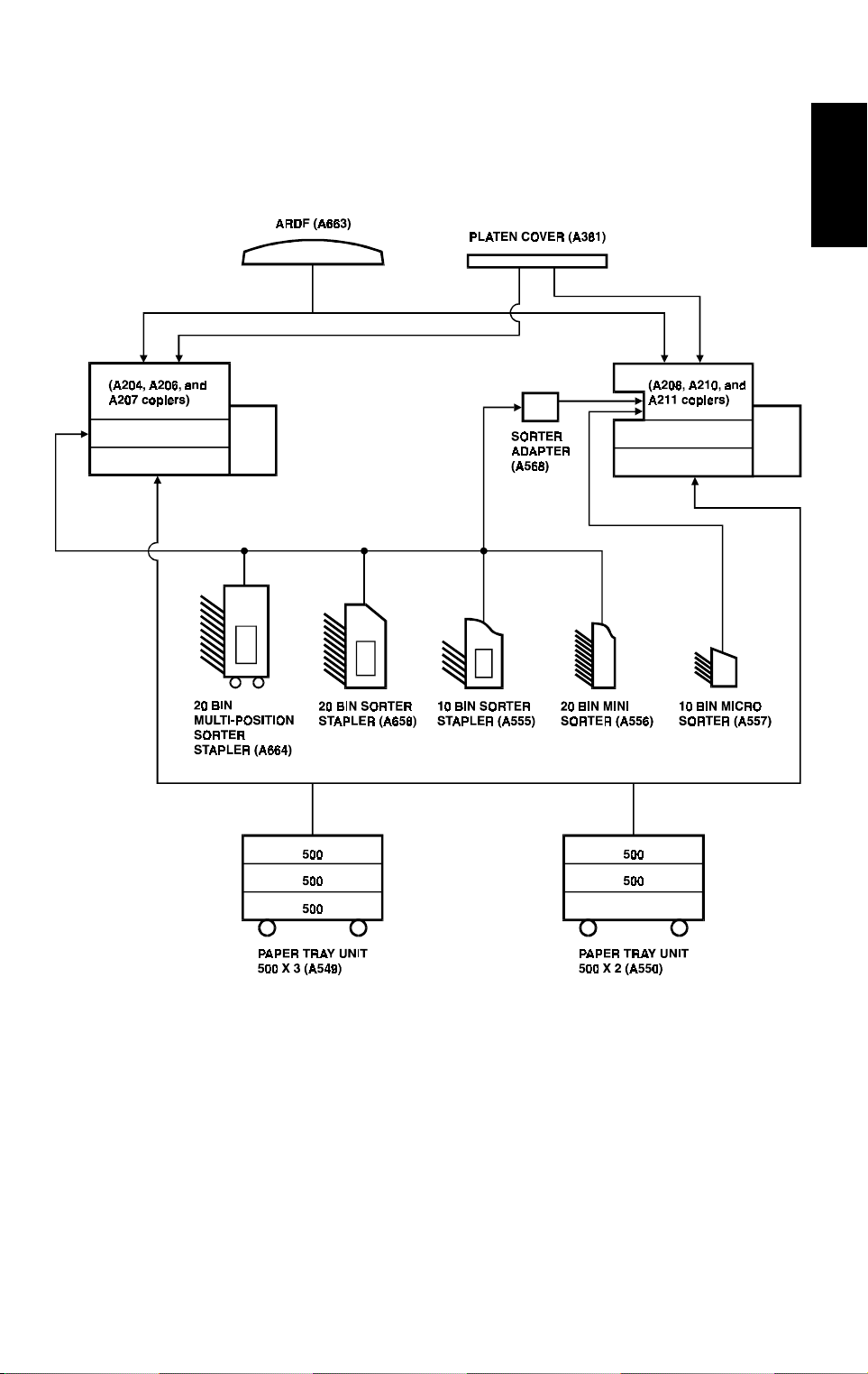
✽ Optional Equipment:
Platen cover
•
Document feeder
•
Paper tray unit with two paper trays
•
Paper tray unit with three paper trays
•
10 bin micro sorter (for A208, A210, and A211
copiers)
•
20 bin mini sorter
•
10 bin sorter stapler
•
20 bin sorter stapler
•
20 bin multi-position sorter stapler
•
Sorter adapter (required when installing 20 bin
mini sorter, 10 bin sorter stapler, 20 bin sorter
stapler, or 20 bin multi-position sorter stapler for
A208, A210, and A211 copiers)
•
Key counter
•
Tray heater
4

31 March 1997 SPECIFICATIONS
•
Optical anti-condensation heater
•
Original length sensor for 11" x 15" size paper
(only for LT/DLT version)
•
ADS sensor for particular types of red original
•
Specifications are subject to change without notice.
Copier
5
MACHINE CONFIGURATION 31 March 1997
2. MACHINE CONFIGURATION
2.1 COPIER
A204V500.wmf
6
31 March 1997 MACHINE CONFIGURATION
2.2 OPTIONAL EQUIPMENT
Copier
A204V501.wmf
7
MECHANICAL COMPONENT LAYOUT 31 March 1997
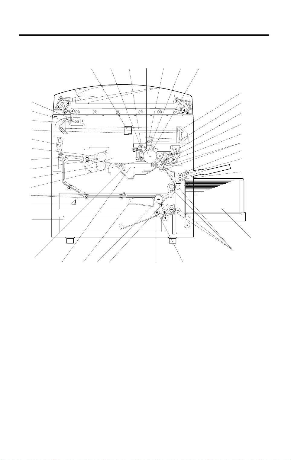
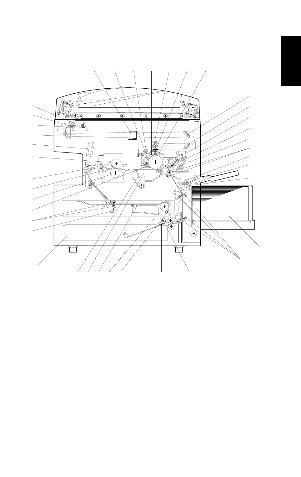
3. MECHANICAL COMPONENT LAYOUT
– A207 copier –
56 91011
4
3
2
1
38
37
36
35
34
33
32
31
87
12
13
14
15
16
17
18
19
20
30
22
29
28 27 26 25 24
23
A204V502.wmf
The fusing unit has been changed. (See Detailed Descriptions for more
information.)
NOTE:
1) The A204 copier is the same as the A207 copier except that the
A204 does not have a duplex tray or an LCT.
2) The A206 copier is the same as the A207 copier except that the
A206 does not have a duplex tray.
21
8
31 March 1997 MECHANICAL COMPONENT LAYOUT
– A211 copier –
4
3
2
1
38
37
36
35
34
33
32
31
56 91011
87
Copier
12
13
14
15
16
17
18
19
20
21
22
30
28 27 26 25
29
24
23
A204V503.wmf
The paper tray unit has been changed from the corner separation system to
the FRR feed system.
NOTE:
1) The A208 copier is the same as the A211 copier except that the
A208 does not have a duplex tray or an LCT.
2) The A210 copier is the same as the A211 copier except that the
A210 does not have a duplex tray.
9

MECHANICAL COMPONENT LAYOUT 31 March 1997
1. 3rd Mirror
2. 2nd Mirror
3. 1st Mirror
4. Exposure Lamp
5. Lens
6. Quenching Lamp
7. Drum Cleaning Blade
8. Drum Charge Roller
9. 6th Mirror
10. OPC Drum
11. Erase Lamp
12. 4th Mirror
13. 5th Mirror
20. Separation Roller
21. Large Capacity Tray
22. Vertical Transport Rollers
23. Paper Feed Roller
24. Friction Pad
25. Duplex Friction Roller
26. Duplex Feed Roller
27. Jogger Fence
28. Transfer Belt
29. Transfer Belt Cleaning Blade
30. Lower Paper Tray
31. End Fence
32. Entrance Rollers
14. Toner Supply Unit
15. Pre-transfer Lamp
16. Development Unit
17. Registration Rollers
18. Feed Roller
19. Pick-up Roller
33. Pick-off Pawls
34. Pressure Roller
35. Hot Roller
36. Junction Gate
37. Hot Roller Strippers
38. Exhaust Fan
10

31 March 1997 ELECTRICAL COMPONENT DESCRIPTIONS
4. ELECTRICAL COMPONENT DESCRIPTIONS
Refer to the electrical component layout and the point to point diagram on the
waterproof paper in the pocket for symbols and index numbers.
✽ : New or modified components
Symbol Name Function Index No.
Printed Circuit Boards
PCB1
PCB2
PCB3 DC Power Supply Provides dc power. 10
PCB4 Main Motor Co nt rol Controls the rotat ion of the main moto r. 94
PCB5
PCB6 T High Voltage Supply Supplies high voltage to the transfer belt. 52
PCB7
PCB8
PCB9
PCB10
PCB11
Main Control Controls all copier functions both directly or
through other control boards.
AC Drive Provides ac power to the exposure lamp
and fusing lamps.
CB High Voltage Supply Supplies high vo ltage to the drum charg e
roller and development roller.
Operation Pan e l Controls the LED matri x, and monitors th e
key matrix.
Noise Filter (220 ~ 240
V machines only)
Duplex Control
(Duplex mac h in es only)
Liquid Crystal Display
(A207 machines only)
LCT Interface
(LCT machines only)
Removes elect rical noise.
Controls the oper ation of the duplex tray.
Controls the gui dance dis play and displays
guidance for machine opera tion.
Interfaces the LCT control signal between
the main board and the LCT.
13
11
1
3
8
60
6
100
Copier
Motors
M1 Main Drives the ma i n uni t com ponents. 85
M2
M3
✽
M4
✽
M5
M6 Optics Cool i ng Fan 1 Removes h eat from the optics unit. 92
M7
✽
M8
Toner Bottle Drive Rotates the toner bottle to supply toner to
the toner supply u ni t .
Upper Tray Lift
(Non-duplex machines
only)
Lower Tray Lift Raises the bottom pl ate in the lower paper
LCT Lift
(LCT machines only)
Optics Cooling Fan 2 Removes h eat from the optics unit .
Exhaust Fan 1 Removes the heat from around the fusing
Raises the bottom pl ate in the uppe r paper
tray.
A204/206/208/ 210: M3 and M4 are
✽
combined into one unit
tray.
Lifts up and lower s t he LC T bottom plat e.
A208/210/211 now have two fans.
✽
unit.
11
76
95
83
97
93
87

ELECTRICAL COMPONENT DESCRIPTIONS 31 March 1997
Symbol Name Function Index No.
M9
Exhaust Fan 2
(A204/A206/A207
Removes the heat fr om ar ound the fusing
unit.
88
machines only)
M10
Scanner Drive Drives the 1st and 2nd scanners (dc
stepper motor ).
90
M11 3rd Scanner Drive Drives the 3rd scanner (dc stepper motor). 75
M12 Lens Vertical Drive Shifts the lens vertical position. 84
M13 Lens Horizont al D r i ve Shifts th e l ens horizontal p osi t i on. 74
M14
M15
M16
M17
✽
Duplex Feed
(Duplex mac h in es only)
End Fence Jogge r
(Duplex mac h in es only)
Side Fence Jogger
(Duplex mac h in es only)
DC Board Cooling Fan
Motor (A204/A206/A207
Drives the feed roller and moves the
bottom plate up and down.
Drives the end f ence jogger to squar e t he
paper stack.
Drives the side f ence jogger to squar e the
paper stack.
55
58
57
Removes heat from t he dc power supply
board. 86
N. American mo del s)
Sensors
S1
S2
S3
S4
S5
✽
S6
S7
S8
✽
By-pass Feed Paper
Width
Informs the CPU what width paper is in the
by-pass feed ta bl e.
By-pass Feed Pa per End Informs the CPU that ther e i s no paper in
the by-pass tray.
Upper Tray Paper End
(Non-duplex machines
Informs the CPU wh en the upper paper
tray runs out of pap er. 48
only)
Upper Relay Detects the leadi ng edge of paper f ro m the
upper tray to dete rm i ne the stop timi ng of
the upper paper fee d clutch, and detects
misfeeds.
Upper Tray Upper Limit
(Non-duplex machines
only)
Detects the hei ght of the paper stack i n the
upper paper tray t o stop the upper tray lif t
motor.
A208/210/211 have the compone nt s
✽
needed for an FRR m echanism.
Lower Tray Paper End Informs the CPU when the l ow er paper tray
runs out of paper.
Lower Relay Detects the le ading edge of pape r from the
lower paper tray to determine the stop
timing of the low er paper feed clutch, and
detects misfeeds.
Lower Tray Upper Limit Detects the height of the paper stack in t he
lower paper tray to stop the lower tr ay l i f t
motor.
A208/210/211 have the compone nt s
✽
needed for an FRR m echanism.
26
30
105
28
49
104
29
12

31 March 1997 ELECTRICAL COMPONENT DESCRIPTIONS
Symbol Name Function Index No.
S9
S10
S11
S12
S13
S14
S15
S16
S17
S18
S19
S20 Fusing Exit Detects mis fe eds. 42
S21
S22
S23
S24
S25
S26
S27
S28
LCT Lower Limit
(LCT machines only)
LCT Paper End
(LCT machines only)
LCT Upper Limit
(LCT machines only)
Registrati on Detects the leading edge of the copy pape r
Image Densi ty (I D) Detects the density of various patterns on
Toner Densi t y (TD) Detects the toner concentrat i on i nside the
Lens Horizont al H P Informs the CPU tha t the l ens is at the
Lens Vertical HP Informs the CPU that the lens is at the
Scanner HP Informs the CPU when the 1st and 2nd
3rd Scanner HP Informs the CPU when the 3rd scanner is
Original Length-2 Detects the lengt h of the original . Th i s i s
Platen Cover Informs the CPU whether the pl at en cover
Toner End Instructs the CPU to add toner to the toner
Auto Response Returns the operation panel display and
Transfer Belt Co nt act HP Informs the CPU of the current position of
Auto Image Density
(ADS Sensor)
Original Width Detects the width of the original. This is
Original Length-1 Detects the lengt h of the original . Th i s i s
Duplex Paper End
(Duplex mac h in es only)
Sends a signal to th e C P U to stop lowering
the LCT bottom p late.
Informs the CPU wh en the LCT runs out of
paper.
Sends a signal to th e C P U to stop lifting
the LCT bottom p late.
to determine the stop timing of the paper
feed clutch, and d et ect s misfeeds.
the drum durin g pr ocess control.
development unit.
horizontal ho me position.
full-size position.
scanners are at the h om e position.
at the home posit i on.
one of the APS (Auto Paper Select)
sensors.
is up or down (related to APS/ARE
functions). ARE: Auto R educe and Enlarge
supply unit, and detects toner end
conditions.
exits from the energy saver mode.
both the transfer belt unit and th e dr um
charge roller uni t .
Detects the background density of each
original in ADS mo de.
one of the APS (Auto Paper Select)
sensors.
one of the APS (Auto Paper Select)
sensors.
Detects paper i n t he duplex tray.
98
99
25
27
47
50
36
19
14
23
20
15
51
40
22
12
41
18
53
Copier
13

ELECTRICAL COMPONENT DESCRIPTIONS 31 March 1997
Symbol Name Function Index No.
S29
Duplex Turn
(Duplex mac h in es only)
Detects the trailing edge of the copy paper
to determine the jo ggi ng timing, an d
54
detects misfeeds.
S30
S31
S32
S33
Duplex Entrance
(Duplex mac h in es only)
Side Fence Jogger HP
(Duplex mac h in es only)
End Fence Jogge r HP
(Duplex mac h in es only)
Original Length
(Option for N. American
Detect s m i sfeeds.
Detects the hom e position of the duplex
side fence jogger.
Detects the hom e position of the duplex
end fence jogger.
Detects orig inal l ength for 11" x 15" p aper.
59
56
61
21
models)
Switches
SW1
SW2
SW3
✽
By-pass Feed Table Detects whether the by-pass feed table is
open or closed.
Tray Down
(LCT machines only)
Upper Tray Paper Siz e
(Non-duplex machines
only)
Sends a signal to the CPU to lower the
LCT bottom plate.
Determines w hat si ze of paper is in th e
upper paper tray, and detects when th e
tray has been cl osed.
The upper tray swi t ch has been
✽
32
102
24
eliminated.
Lower Tray Pap er Siz e Determines what size of paper is in the
lower paper tray, and detects when the tray
SW4
✽
has been closed.
The lower tray switch has been
✽
33
eliminated.
SW5
Vertical Guide Set
(Non-LCT m achines
Detects whether the vertical gui de i s open
or not. 31
only)
SW6
SW7
LCT Cover-1
(LCT machines only)
LCT Cover-2
(LCT machines only)
Detects whether the LCT cover is ope n or
not.
Cuts the dc power l i ne of the LCT lift motor.
103
101
SW8 Main Supplies power to t he copier. 39
SW9
SW10
Front Cover Saf e t y Cuts the ac power line and detects whether
the front door is open or not.
Exit Cover Safety
(A211 machines only)
Cuts the ac power l i ne and detects whet her
the exit cover is open or not.
38
45
Magnetic Clutches
CL1
Toner Supply Turns the toner supply roller to supply
toner to the devel opment unit.
CL2 Dev elopment Drives t he develo pment roller. 68
14
69

31 March 1997 ELECTRICAL COMPONENT DESCRIPTIONS
Symbol Name Function Index No.
Transfer Belt Co nt act Controls the touch and releas e m ovement
CL3
CL4 Registration Drives the registration rollers. 70
CL5
CL6 Relay Drives the relay rollers. 73
CL7
CL8 Lower Paper Feed Starts paper feed fr om the lower paper tr ay. 82
Solenoids
SOL1
SOL2
SOL3
SOL4
✽
SOL5
✽
SOL6
✽
SOL7
✽
By-pass Feed Starts paper feed from the by-pass feed
Upper Paper Feed
(Non-duplex machines
only)
LCT machines:
LCT/By-Pass Pick -u p
Solenoid
Non-LCT machi nes:
By-pass Pick-up
Solenoid
Junction Gate
(Duplex mac h in es only)
LCT Pick-up
(LCT machines only)
Upper Tray Pick-up
(Non-duplex machines
only)
Lower Tray Pick -up Controls the up/ down movement of th e
Upper Tray Separ at i on
(Non-duplex machines
only)
Lower Tray Separation Controls the up-down movement of the
of both the transfer bel t uni t and the drum
charge roller uni t .
table or LCT.
Starts paper feed from the upper paper
tray. 81
Picks paper up from t he by-pass feed
table. When paper is fed from the LC T, this
solenoid ass i st s SO L3.
Moves the junction gate to direc t copies to
the duplex tray or to the paper exit.
Picks up paper from t he LC T.
Controls the up/down movement of the
pick-up roller i n the upper paper tray.
A208/210/211 have the compone nt s
✽
needed for an FRR m echanism.
pick-up roller i n the lower paper tr ay.
A208/210/211 have the compone nt s
✽
needed for an FRR m echanism.
Controls the up- down move m ent of the
separation rol l er in the upper pap er tr ay
feed station.
A208/210/211 have the compone nt s
✽
needed for an FRR m echanism.
separation rol l er in the lower pa per tr ay
feed station.
A208/210/211 have the compone nt s
✽
needed for an FRR m echanism.
91
71
72
89
96
77
79
78
80
Copier
Lamps
L1
✽
Exposure Applies high intensity light to the original for
exposure.
Modified - see the "O pt i cs" section for
✽
details.
15
16

ELECTRICAL COMPONENT DESCRIPTIONS 31 March 1997
Symbol Name Function Index No.
Main Fusing Provides heat to the central area of the hot
L2
✽
roller.
Modified - see the "Fusing" section for
✽
62
details.
Secondary Fu si ng Provides heat to both ends of the hot roller.
L3
✽
Modified - see the "Fusing" section for
✽
63
details.
Pre-transfer Red uces the charge re maining on the
L4
drum surface bef or e t ransfer. 4
Quenching Neutralizes any charge rem a in ing on the
L5
drum surface af te r cleaning.
5
Erase After exposure, this eliminates the charge
L6
on areas of the drum that will not be used
2
for the image.
Heaters
Drum Turns on when the main switch is off to
keep the temperature around the drum
H1
charge roller at a certain level. Also
35
prevents moisture from forming around the
drum.
H2
Optics Anti-c ondensation
(option)
Turns on when the main switch is off to
prevent moisture from forming on the
43
optics.
H3
Lower Tray (option) Turns on when the main switch is off to
keep paper dry i n th e l ow er paper tray.
34
Thermistors
TH1
Main Fusing Monitors the tem perature at the central
Secondary Fu si ng
TH2
✽
(A208/A210/A2 11
machines only)
TH3
TH4
Optics Monitors the temperature of the optics
Drum Charge Monitors the temperature of the drum
Thermofuses
TF1
Main Fusing Provides back-up overheat pro te ct i on i n
Secondary Fu si ng
TF2
✽
(A208/A210/A2 11
machines only)
area of the hot roll er.
Monitors the tem perature at the e nds of the
hot roller.
A204/206/207 have only one thermi st or.
✽
cavity.
charge roller .
the fusing unit.
Provides back- up overheat pro te ct i on i n
the fusing unit.
A204/206/207 have only one thermofuse.
✽
16
66
67
44
46
65
64

31 March 1997 ELECTRICAL COMPONENT DESCRIPTIONS
Symbol Name Function Index No.
TF3
Counters
CO1
CO2
Others
CB1
TR1
CC1 This has been eli minated from all m odels.
Exposure Lamp Opens the exposure lamp circuit if the 1st
scanner overheats.
Total Keeps t rack of the total num ber of copies
made.
Key (option) Used for co nt rol of authorized use. The
copier will not operate until it is installed.
Circuit Breaker (220 ~
240 V machines onl y)
Transformer (220 ~ 240
V machines only)
Provides back-up high current protection
for electrical components.
Steps down the wall voltage to 100 Vac.
17
37
N/A
9
7
Copier
17
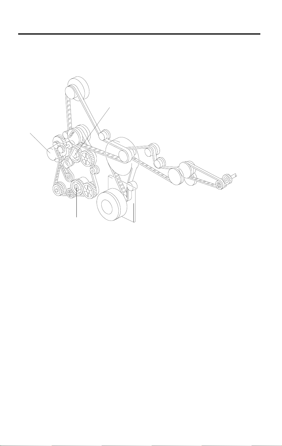
PAPER FEED DRIVE LAYOUT 31 March 1997
5. PAPER FEED DRIVE LAYOUT
5.1 A204/A206/A207/A208/A210/A211
1
3
2
A204V504.wmf
Since A208, A210, and A211 have been changed to the FRR feed system, all
models carry the same type of drive layout.
1. Upper Paper Feed Clutch Gear (A207/A211 only)
2. Lower Paper Feed Clutch Gear
3. Relay Clutch Gear
18

31 March 1997 PROCESS CONTROL
6. PROCESS CONTROL
6.1 HALFTONE MODE
This mode is newly added.
If the user selects the halftone mode function on the operation panel, the
machine reduces the size of the exposure lamp voltage, development bias,
and the drum charge voltage by the changes shown below.
•
Exposure Lamp Voltage: –1.0 V
•
Development Bias: +80 V
•
Drum Charge Voltage: +300 V
6.2 ADS CORRECTION
✽ Five possible corrections can be selected from, where the base copier has
only three.
Copier
ADS correction
ADS Density SP5-106
Setting Copy Density
0 Dar kest 816 x (AR – 0.85) + 60
✽
1 Darker 816 x (AR – 0.75)
2 Nor m al 816 x (AR – 0.85)
3 Lighter 816 x (AR – 0.95)
4 Lightest 816 x (AR – 0.85) – 60
✽
Where AR (ADS Ratio) = V
Development Bi as C orrection Voltage
ADS
(original)/V
ADS
(pattern)
19

PROCESS CONTROL 31 March 1997
6.3 TONER SUPPLY CONTROL DURING COPYING
✽ The amount of toner supplied per unit of time (TS) has been changed from
the base copier.
Toner clutch on time is calculated by the following formula.
Toner CL on time [ms] =
S x
AT x
TSC
TS
⁄⁄
100
(Formula 1)
where: S = Copy paper size [cm
AT = Amount of toner developed on the latent image per unit area
= 0.7 [mg/cm
2
] (constant)
TSC = Toner supply coefficient [%]
✽ TS= Amount of toner supplied per unit of time
= 0.217 [mg/ms] (for A204, A206, and A207 copiers)
= 0.183 [mg/ms] (for A208, A210, and A211 copiers)
2
]
20
31 March 1997 PROCESS CONTROL
6.4 VR PATTERN CORRECTION
✽ The values in the ID correction column of the table have been changed.
R
correction
V
ID Correction
–40 V –80 V
V
RP/VRG
100 (%)
x
±±
0 V
74 ~ 100 68 ~ 100 62 ~ 100
53 ~ 73 50 ~ 67 43 ~ 61 –40 V –40 V
41 ~ 52 37 ~ 49 26 ~ 42 –80 V –80 V
31 ~ 40 26 ~ 36 19 ~ 25 –120 V –120 V
0 ~ 30 0 ~ 25 0 ~ 18 –160 V –160 V
For example, taking the ID correction to be zero for now, if VRP/V
Drum Charge Roller
Correction Voltage
0 V
±
Development Bia s
Correction Volt age
0 V
±
RG
is 45%,
the drum charge and development bias corrections will both be –80 V.
R
V
correction also depends on the current VSP pattern ID correction that is
being used. If development bias has been increased by ID correction, the V
correction may be smaller in some cases to take this into account. This is
shown by both the table above and the following diagram.
–160 V
–120 V
ID correction
0 V
–40 V
–80 V
Copier
R
–80 V
–40 V
Correction Voltage
R
V
–0 V
10080604010 20 30 50 70 90
Drum residual
voltage largel
VRP/VRG (%)
Drum residual
voltage small
A204D505.wmf
Using the same example to illustrate this, but with an ID correction of –80 V,
the corrections will both be –40 V this time.
21

PROCESS CONTROL 31 March 1997
6.5 TONER SUPPLY IN ABNORMAL SENSOR CONDITIONS
If any sensor errors occur under detect supply mode, toner supply mode is
changed automatically as shown below.
Error Abnorma l Cond ition
ID Sensor
Adjustment Error
Abnormal ID Sensor
SP
)
(V
Abnormal ID Sensor
SG
)
(V
TD Sensor
Adjustment Error
TD Sensor (V
T
)
Measurem ent Error
Drum Charge
Thermistor Error
Abnormal Drum
✽
Charge Thermistor
Output
When ID senso r output
cannot be adjusted to
4.0 ± 0.2 V
SP
> 2.5 V during
If V
SP
V
detect i on.
SG
If V
< 2.5 V during
SG
detection
V
When TD sensor
output cannot be
adjust ed to 2.5 ± 0.1 V
If VT > 4.0 V or VT <
0.3 V during V
T
detection.
Temperature det ected
by the drum cha rge
thermistor is below 0°C
or above 60°C
Temperature det ected
by the drum cha rge
thermistor is between
0°C and 14°C
Fallback Toner
Supply Mode
Display on
Operation Panel
Fixed Supply Mode None
Fixed Supply Mode None
Fixed Supply Mode
Fixed Supply Mode Manual ID level or
ADS indicator blinks
Fixed Supply Mode Manual ID level or
ADS indicator blinks
Fixed Supply Mode None
TD Sensor Supply
None
Mode
NOTE:
No indication is displayed under the "abnormal drum charge
thermistor output" condition, because the machine soon recovers
due to the heat inside the machine.
22
31 March 1997 PROCESS CONTROL
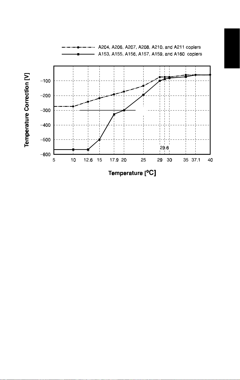
6.6 TEMPERATURE CORRECTION
[A]
Copier
A204D506.wmf
✽ The temperature correction has changed as explained below. Also, the
machine no longer does the drum rotation time correction.
The temperature correction difference between the A204, A206, and A207
copiers and the A208, A210, and A211 copiers is a result of the difference in
copy processing speed (240 mm/s for the A204, A206, and A207 copiers,
compared with 200 mm/s for the A208, A210, and A211 copiers).
The new drum charge roller needs only about half the correction voltage
used for the base copier. Also, the level of correction needed for the lowest
temperature point (5°C) is about the same as the normal room temperature
point for the base copier [A].
In the base machine, rotation time correction was only needed for low
temperatures where the temperature correction was large. In the new
machines, the temperature correction is never greater than –300 V, so the
rotation time correction has been eliminated.
23

PROCESS CONTROL 31 March 1997
The temperature corrections are as shown below.
•
Temperature Correction (Copying) - Base drum charge voltage = –1,500 V
•
Temperature Correction (VSP Pattern) - Base drum charge = –1,370 V
– A204, A206, and A207 –
Drum Charge Roller
Temperature (°C)
35.0 ≤ T
28.0 ≤ T < 35.0
10.0 ≤ T < 28.0
T < 10.0 –130.0 –295.0
– A208, A210, and A211 –
Drum Charge Roller
Temperature (°C)
35.0 ≤ T
29.0 ≤ T < 35.0
10.0 ≤ T < 29.0
T < 10.0 –120.0 –260.0
Temperature Correcti on
V
Pattern Copying
SP
+53 –57.0
–83.5 + 3.9T –211.0 + 4.4T
–217.6 + 8.7T –410.0 + 11.5T
Temperature Correcti on
V
Pattern Copying
SP
+47 –61.0
–51.0 + 2.8T –173.0 + 3.2T
–199.1 + 7.9T –3 55.5 + 9.5T
24

31 March 1997 PROCESS CONTROL
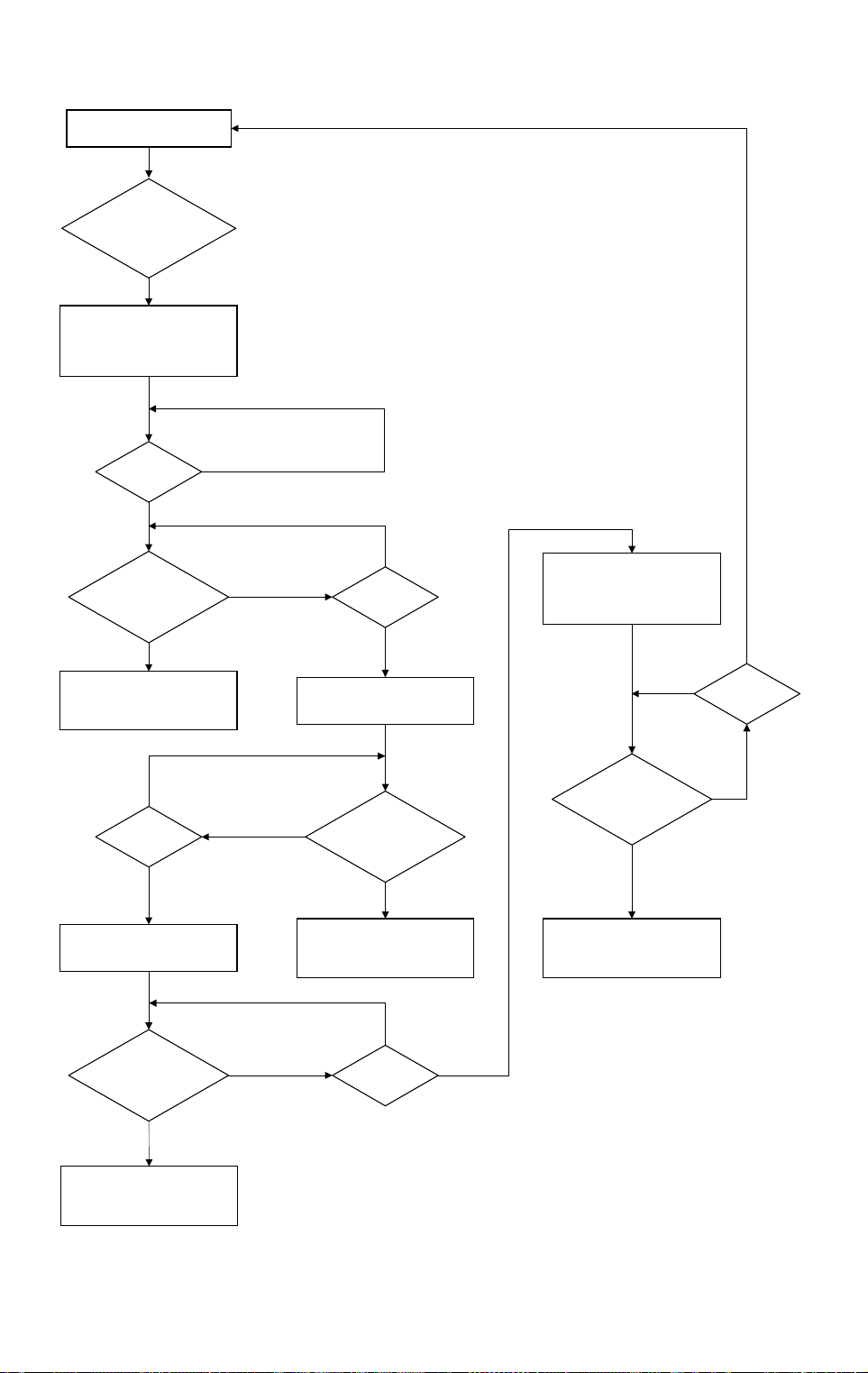
6.7 TONER END RECOVERY
If the front cover switch or the main switch is turned off and on during a toner
near-end/end condition, the machine will perform the toner end recovery
procedure as shown on the flow chart on the next page.
For the base copier, the toner end sensor checked for toner for a total of 10
seconds. The check stops when the toner supply clutch stops transporting
toner.
For the A204 series, the toner sensor checks for toner for a total of 14
seconds, stopping 2 seconds after the toner supply clutch stops. When the
toner supply clutch stops, any toner present is likely to drop into the
development unit, which will be detected during the final 2 seconds of
detection time. This will decrease the chances of a mis-detection when a new
toner bottle has been installed by the customer.
Copier
A153/A155/A156/
A157/A159/A160
A204/A206/A207/
A208/A210/A211
Toner Supply
Clutch
Toner End
Sensor
Toner Supply
Clutch
Toner End
Sensor
ON
OFF
ON
OFF
ON
OFF
ON
OFF
10
2
2 255
2
A204D516.wmf
25
PROCESS CONTROL 31 March 1997
Toner End Condition
Yes
Front
Cover Switch or Main
Switch Turned OFF/
ON?
Yes
Drum Drive, Development
Clutch, Toner Supply Clutch,
Toner Bottle Drive Motor
Turn On. t = 0s.
t ≥ 2s
Toner End
Detection. Is Toner
Present?
Components Turn Off. Toner
End/Near End Condition is
Canceled.
t ≥ 7s
Toner Supply Clutch, Toner
Bottle Drive Turn On.
No
Yes
No
Yes
No
Yes
No
t ≥ 5s
Yes
Toner Supply Clutch, Toner
Bottle Drive Turn Off.
Toner End
Detection. Is Toner
No
Components Turn Off. Toner
Present?
Yes
End/Near End Condition is
Canceled.
Drum Drive, Development
Clutch, Toner Supply Clutch,
Toner Bottle Drive Motor
Turn Off.
No
Toner End
Detection. Is Toner
Present?
Yes
Components Turn Off. Toner
End/Near End Condition is
Canceled.
No
Yes
t ≥ 14s
Toner End
Detection. Is Toner
Present?
Yes
Components Turn Off. Toner
End/Near End Condition is
Canceled.
t ≥ 12s
No
YesNo
A204D515.wmf
26
31 March 1997 PROCESS CONTROL
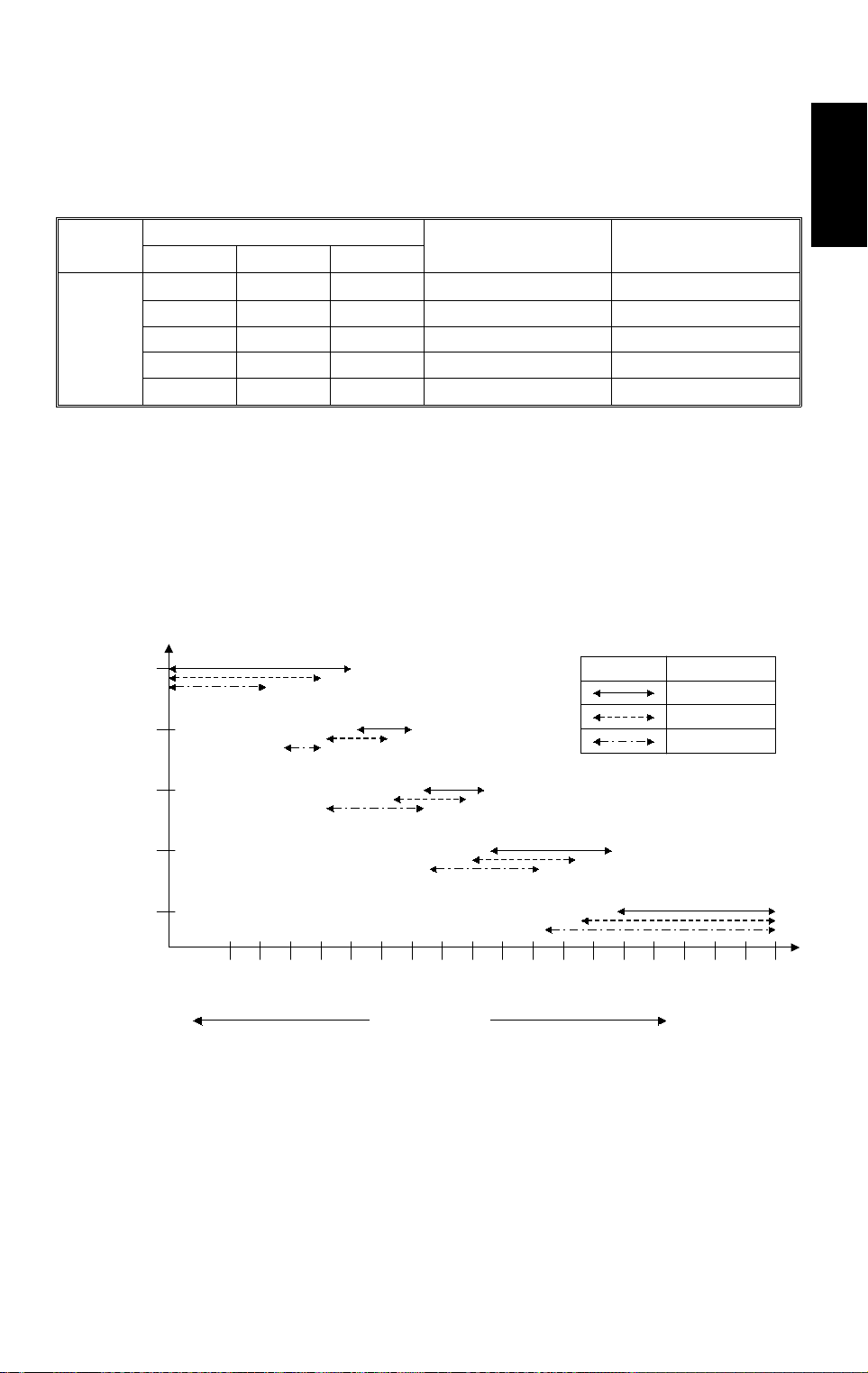
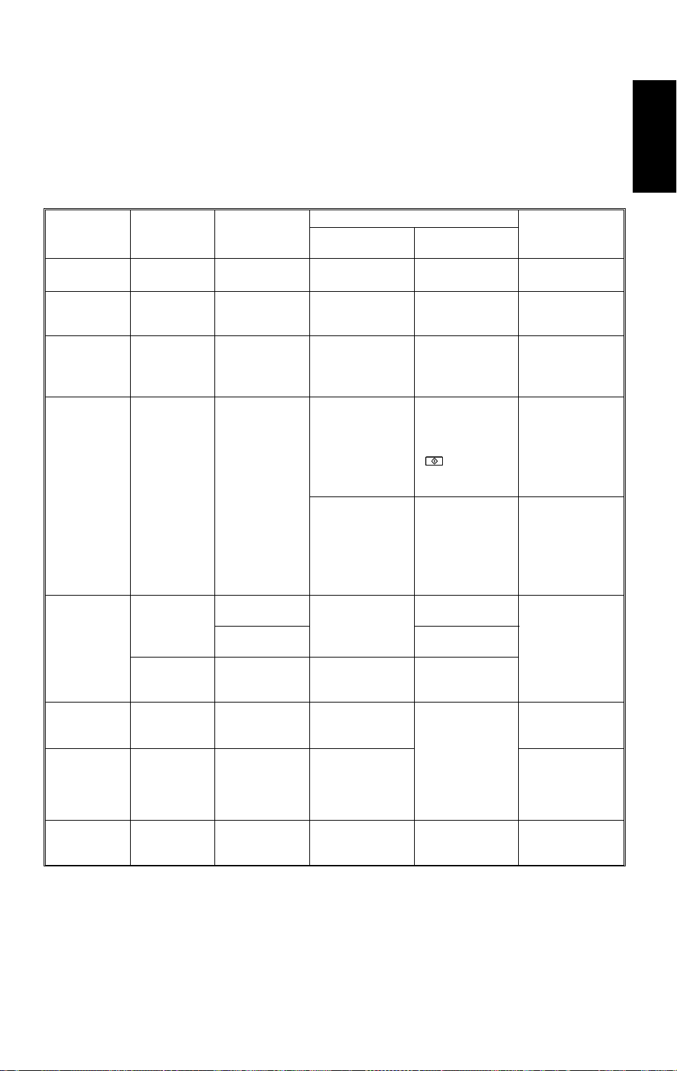
6.8 SUMMARY
NOTE:
Only items marked with ✽ are different or reviewed from A153, A155,
A156, A157, A159, and A160 copiers.
A summary of process control and correction timing is shown below.
Correction
Manual ID
correction
Reproduction
ratio
correction
✽
Halftone mode
ADS
correction
ID
correction
and
Toner density
control
R
V
correction
L
V
correction
✽
Temperature
correction
Electrical
Component
Operation
panel
Operation
panel
Operation
panel
ADS sensor
ID sensor
TD sensor VT
ID sensor V
ID sensor V
Drum charge
roller
thermistor
Sensor Output
V
ADS
V
ADS
T: (temperature) —
Used
——
——
——
Forced Correction
(pattern)
(original)
SG
V
SP
V
RP
, V
LP
, V
New exposure
lamp, ADS sensor,
after SP4- 001
(Exposure lamp
voltage
adjustment) or
optics cleaning
New drum, ID
sensor or ID
sensor cleaning
When the
developer is
changed
New drum or ID
sensor replacement
RG
New drum,
exposure lamp or
LG
after SP4- 001
(Exposure lamp
voltage adj ustment)
Correction Timing
Every copy in
manual ID mode
Every copy in
reduce/enlarge
mode
Every copy in
halftone mode
ADS Mode:
•
Once per original
—
(ARDF mode), or
once when the
! key is
pressed (Platen
mode)
Every 1,000 copies
At the start of
each copy job
About every 10
copies
Every copy
After every 1,000
copies
Every copy Drum charge roller
Automatic
Correction
Corrected Value
Lamp voltage
•
Dev. bias
•
Development bias
Lamp voltage
•
Dev. bias
•
Drum charge
•
roller voltage
Development bias
ADS
V
•
(pattern)
is stored
Dev. bias
•
Toner supply
•
clutch ON
time
Drum charge
•
roller voltage
Dev. bias
•
Lamp voltage
voltage
Copier
27
 Loading...