

Page 1
I{ll(txml”
.
.
CUSTOMER SERVICE
FT505015070
FIELD SERVICE MANUAL
REV.NO.
1-
& -—- + -–—— — ——--
—. —-
— —.-———— -
.
DATE COMMENTS
5191
OrmnalPnntma
—
—.—
—.
—
1
~-. -— – .--—
L- —. —._
——
—
.
.
—-
—
“’:-1
3
PN RCFtV15050
Page 2

.
Page 3

WARNING
r
The Field Service Manual contains information
regarding service techniques, procedures,
processes and spare parts of office equipment
distributed by Ricoh Corporation. Users of this
manual should be either service trained or
certified by successfully completing a Ricoh
Technical Training Program.
Untrained and uncertified users utilizing
information contained in this service manual to
repair or modify Ricoh equipment risk personal
injury, damage to property, or loss of warranty
protection.
1
mcoh corporation
J
Page 4

————
.-
Page 5
Table of Contents
SECTION 1. INSTALLATION REQUIREMENTS
1-1
1-2
1-3
1-4
Environment ..............................................................................................................
Machine Level ...........................................................................................................
Minimum Space Requirements ..................................................................................
Power Sourm ............................................................................................................
SECTiON 2. UNPACKING AND INSTALLATION
Installation-Setup Checklist
2-1
2-2 Accessory Checklist ..................................................................................................
2-3
2-4
2-5 Key Counter Holder installation ..................................................................................
2-6
Unpacking Procedure ...................................................................... .........................
Installation Procedure ................................................................................................
Cassette Modification .
Main Transformer Conversion ....................................................................................
...............................................................................................
SECTION 3. PREPARATION FOR TRANSPORTING COPIER
Pr+aratbn for Trans~fii~ the Copier ..................................................................................
SECTION 4. REMARKS
4-1
4-2 Handling the Dmm .....................................................................................................
Points to Remember ..................................................................................................
1-1-1
1-2-1
1-3-1
1-4-1
2-1-1
2-2-1
2-3-1
2-4-1
2-5-1
2-6-1
3-1-1
4-1-1
4-2-1
SECTION 5. REPLACEMENT AND ADJUSTMENT
1-1
1-2
1-3
1-4
1-5
1-6
1-7
1-8
Exposure Glass Removal ..........................................................................................
Or@inal Stielndkator Board Removal .......................................................................
2ti Mirror Removal ...................................................................................................
Exposure La~Replacement ....................................................................................
Ex~sure Lamp Position ............................................................................................
Scanner Drive Wire Replacement .......
Scanner Drive Motor Replacement ............................................................................
Lens Drive and2nd Scanner Drive Motor Replacement ................... .........................
........................................................... ...........
SECTION 6. SERVICE TABLES
6-1
6-2 Dip Switch Table .......................................................................... ... ............ ............
6-3
6-4 Self-Diagnostic Codes ...............................................................................................
Preventive Maintenance Schedule
6-6 Sp*ial Tmls .............................................................................................................
Adjustment Table .......................................................................................................
Defective Sensor Table ............................................................................................
I
5-1-1
5-1-2
5-1-3
5-1-5
5-1-7
5-1-9
5-1-15
5-1-17
6-1-1
6-2-1
6-3-1
6-4-1
6-6-1
Page 6
.. ..
SECTION 7. TROUBLESHOOTING
1-1
1-2
1-3
14
1-5
1-6
1-7
1-8
1-9
1-1o
1-11
1-12
1-13
7-2
2-1
2-2
2-3
2-4
2-5
2-7
2-8
2-9
2-1o
2-11
2-12
2-13
2-14
2-15
2-16
2-17
2-18
Whtie Copy ................................................................................................................
Dirty Background
Uneven Image Density ..............................................................................................
Vertical Black Line .....................................................................................................
Vertical White Line .....................................................................................................
Horizontal Black Line .................................................................................................
..........................................................................................................................
Jitter
Copy Image is Scraped Off by the Finger Due to Unfused Copy ................................
Scanner Movement is Out of Control
Toner Density is Too Hgh
Toner Density is Too Low ..........................................................................................
Distorted Copy Image ................................................................................................
Mi~ellaneous .......................................................................................................... ..
Electrical and Mechanical
Exposure Lamp Malfunction ..................................................................................... .
Lamp Reiay O~n .................................................................................................... .
Scanner Not in H. P., Delayed H.P. Signal ..................................................................
@emn Swtich ON ....................................................................................................
No Regist Start Signal ...............................................................................................
Lens H.P. Not ON, Lens H.P. Not OFF ......................................................................
2nd Scanner H.P. Not ON, 2nd Scanner H.P. Not OFF .............................................
Hgh Frequency Ender Out~t ................................................................................
Low Frequency Encoder Output ................................................................................
.......................................................................................................
.........................................................................................
Upper Lift Sensor Not ON, Lower Lift Sensor Not ON ................................................
Themtise Blown .....................................................................................................
Themistor Blown ................................................................................................ ......
Ready Sgnal Not ON ................................................................................................
Fundbnal Drive Maltindion ......................................................................................
Jogger H.P. Not ON, Jogger H.P. Not OFF ...............................................................
Counter Malfunction ..........................................................................................
Total
Optics/Main Board ltiedace Malfundion ....................................................................
.........................................................................
7-1-1
7-1-2
7-1-4
7-1-6
7-1-7
7-1-9
7-1-1o
7-1-11
7-1-12
7-1-13
7-1-15
7-1-17
7-1-18
7-2-1
7-2-2
7-2-3
7-2-4
7-2-5
7-2-6
7-2-7
7-2-8
7-2-9
7-2-10
7-2-11
7-2-11
7-2-12
7-2-13
7-2-14
7-2-15
7-2-15
..—
..-
SECTION 8. DOCUMENT FEEDER DF32
8-1 Unpacking
8-2
DF Installation Procedure ..........................................................................................
.................................................................................................................
SECTION 9. SORTER CS1510
9-1 Unpacking Procedure ................................................................................................
2-1 Instaliat.mn Procedure ................................................................................................
SECTION 10. LARGE CAPACITY TRAY RT11
10-1
10-2 Installation Procedure ................................................................................................
3-1
3-2
3-3
3-4
Unpacking Procedure ................................................................................................
Tray Down Sensor and Positioning Switch Replacement ...........................................
Paper Size Sensor Replacement ...............................................................................
Tray Wire Replacement .............................................................................................
Pa~r Volume Cod Replacement ..............................................................................
8-1-1
8-2-1
9-:-1
9-2-1
10-”-1
10-2-1
10-3-1
10-3-3
10-3-4
10-3-7
..44.
Page 7
SECTION 11. ELECTRICAL DATA FT 5050/5070
11-1 Point-to-Point Wiring Diagram
Component and Connector
Reference Vottage Chart
11-4
11-5
11-6
Schematics
Timing Chafi
Board Pattern
Layout
SECTION 12. ELECTRICAL DATA DF32
12-1 DF Point-to-Point/Component and Connector Layout
12-2 DF Timing Chart
12-3
12-4 DF Main Board Pattern
DF Main Board Schematic
SECTION 13. ELECTRICAL DATA CSI 510
13-1 Sorter Point-to-Point/Component and Connector Layout
13-2
13-3 Seder Main Board Schematic
13-4 Sorter Main Board Pattern
Sorter Timing Chart (A3 Mode)
SECTION 14. ELECTRICAL DATA RTI 1
14-1
14-2 Electrical Component and Connector Layout
14-3 Tray Main Board Schematic
14-4 Tray Main Board Pattern
Point-to-Point Wiring Diagram
RETROFIT INFORMATION
Ret refit Information
Page 8

-4 ‘
4
Page 9

SECTION 1
INSTALLATION REQUIREMENTS
Page 10

—
4
Page 11
—.
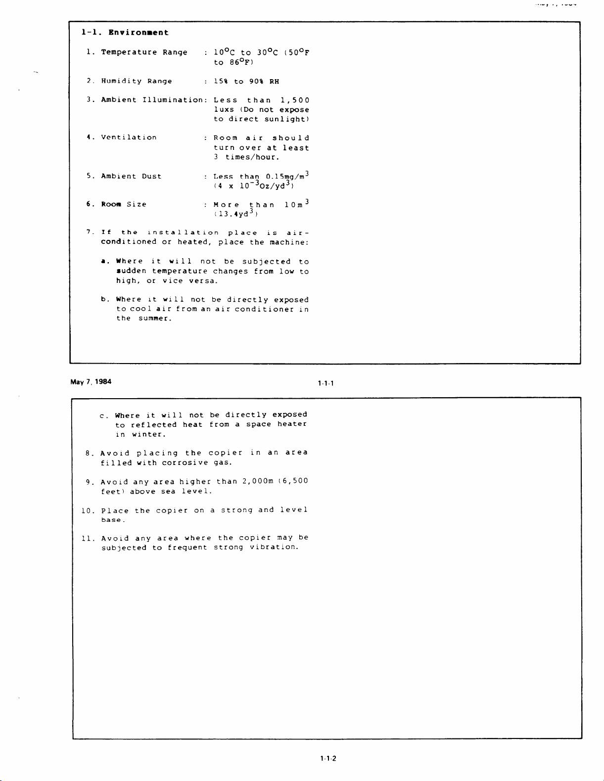
l-l
Environment
.
1.
Temperature Range
: 10°C to 30°C (50°F
to 86°F)
2.
Humidity Range : 15% to 90% RH
3.
Ambient Illumination: Less
lUXS (Do not expose
to direct sunlight)
4.
Ventilation
: Room air
turn over at least
3 times/hour.
5.
Amb~ent Dust
: Less than 0.15mg/m3
(4 x
6.
Room Size
: More
(13.4yd3)
7.
xf
the
conditioned or heated,
Where It w~ll
● ✎
installation place is
place the machine:
not be subjected to
sudden temperature changes from low to
high, or vice versa.
than
10
‘30z/yd3)
than
..-8 ., .-” -
1,500
should
10m3
air–
b. Where it will not be directly exposed
to cool air froman alr conditioner Ln
the summer.
May7,1984
Where it will not be directly exposed
c.
to reflected heat from a space heater
in winter.
8. Avo~d placing the copier in an area
filled with corrosive gas.
9. Avoid any area higher than 2,000m (6,500
feet) above sea level.
10.
Place the copier on
base.
11. Avoid any area where the copier maY be
sub]ected to frequent strong vibration.
a strong and level
1-1-1
1-1-2
Page 12
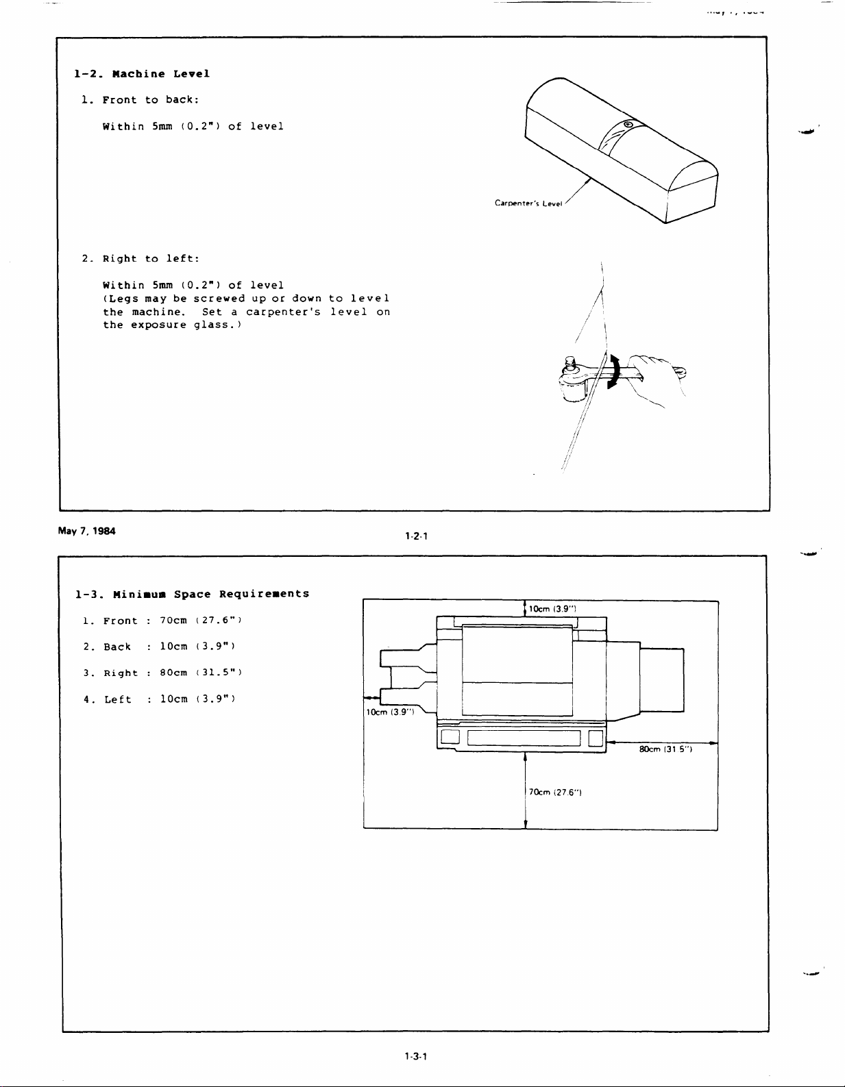
1-2. Machine Level
Front to back
1.
.,.”
., ,”.,-
t
Within 5mm (O
2.
Right to left:
Within 5mm (0.2”)
(Legs may be
the machine.
the exposure
2“)
of
level
of
level
screwed up or down to level
Set a carpenter’s level on
glass. )
—-=-
&-
l._.
+
L ,,
/1
.4 ‘
)
A
,,
,/
I
-R---
/
/
/)
‘\
~
f
May7,1984
1-3.
1.
Front :
2.
Back :
3.
Right :
4.
Left :
Blinimum Space Requirements
(27.6”)
70cm
1Ocm
(3.9”)
(31.5”)
80cm
10cm
(3.9”)
1-2-1
..-
lCkm(39“)
4
I
I
~70cm(276“)
I
1
1-3-1
..-
Page 13

1-4. Power Source
1. Input voltage level
l15v/60Hz
: More than 15A
220v/50Hz : More than 7A
240vi50Hz : More than 7A
2. Permissible voltage fluctuation : flO%
3. Permissible extension cord :
At least 300V, 30A capacity and less than
5m (16.4’” long.
NOTE : 1. Be sure to ground the machine.
(Do not connect the grounding
wire to a gas pipe.)
2. Make sure the plug is
firmly
inserted ~n the outlet.
3. Avoid multl-wiring.
4. Do not set anything on the power
cord.
141
Page 14

,.-
..4
w’
../
Page 15

SECTION 2
UNPACKING AND INSTALLATION
Page 16

Page 17
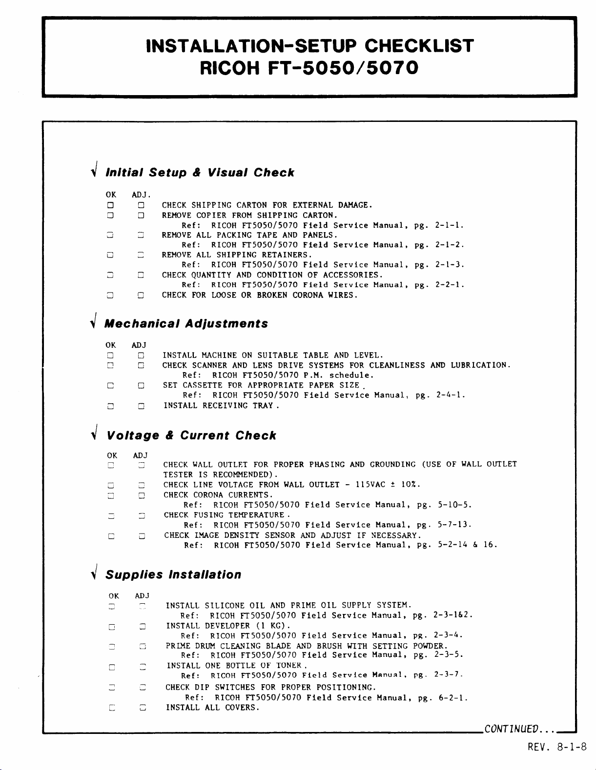
INSTALLATION-SETUP CHECKLIST
RICOH FT-5050/5070
r
~ Initial Setup& Visual Check
OK ADJ .
On
❑ ❑
CHECK SHIPPING
REMOVE COPIER FROM SHIPPING CARTON.
Ref: RICOH FT5050/5070 Field Service Manual, pg. 2-1-1.
REMOVE ALL PACKING TAPE AND PANELS.
Ref: RICOH FT5050/5070 Field Service Manual, pg. 2-1-2.
REMOVE ALL SHIPPING RETAINERS.
Ref: RICOH FT5050/5070 Field Service Manual, pg. 2-1-3.
CHECK QUANTITY AND CONDITION OF ACCESSORIES.
Ref: RICOH FT5050/5070 Field Service Manual,
CHECK FOR LOOSE OR BROKEN CORONA WIRES.
~ Mechanical Adjustments
CARTONFOR EXTERNAL DAMAGE.
pg. 2-2-1.
OK ADJ
•1 o
p
c ❑
a G
INSTALL MACHINE ON SUITABLE TABLE AND LEVEL.
CHECK SCANNER AND LENS DRIVE SYSTEMS FOR CLEANLINESS AND LUBRICATION.
❑
Ref: RICOH FT5050/5070 P.M. schedule.
SET CASSETTE FOR APPROPRIATE PAPER SIZE.
Ref: RICOH FT5050/5070 Field Service Manual, pg. 2-4-1.
INSTALL RECEIVING TIUiY.
~ Voltage& Current Check
OK ADJ
CHECK WALL OUTLET FOR PROPER PHASING AND GROUNDING (USE OF WALL OUTLET
TESTER IS RECOMMENDED).
CHECK LINE VOLTAGE FROM WALL OUTLET - 115VAC t 10%.
CHECK CORONA CURRENTS.
Ref:
CHECK FUSING
Ref: RICOH FT5050/5070 Field Service Manual, pg. 5-7-13.
CHECK IMAGE DENSITY SENSOR AND ADJUST IF NECESSARY.
Ref: RICOH
RICOH FT5050/5070 Field Service Manual, pg. 5-10-5.
TEMPEMTURE.
FT5050/5070 Field Service Manual, Pg. 5-2-14 & 16.
dSupplies Installation
OK ADJ
L-.
1
1
INSTALL SILICONE OIL AND PRIME OIL SUPPLY SYSTEM.
Ref: RICOH FT5050/5070 Field Service Manual, pg.
INSTALL DEVELOPER (1 KG).
-,
u
Ref: RICOH FT5050/5070 Field Service Manual, pg.
PRLME DRUM CLEANING BLADE AND BRUSH WITH SETTING POWDER.
Ref:
INSTALL ONE BOTTLE OF TONER.
Ref:
CHECK DIP SWITCHES FOR PROPER POSITIONING.
INSTALL ALL COVERS.
RICOH FT5050/5070 Field Service Manual, pg. 2-3-5.
RICOH FT5050/5070 Field Service Mnnual, pg. 2-3-7.
Ref: RICOH FT5050/5070 Field Service Manual, pg. 6-2-1.
2-3-162.
2-3-4.
REV. 8-1-8
Page 18
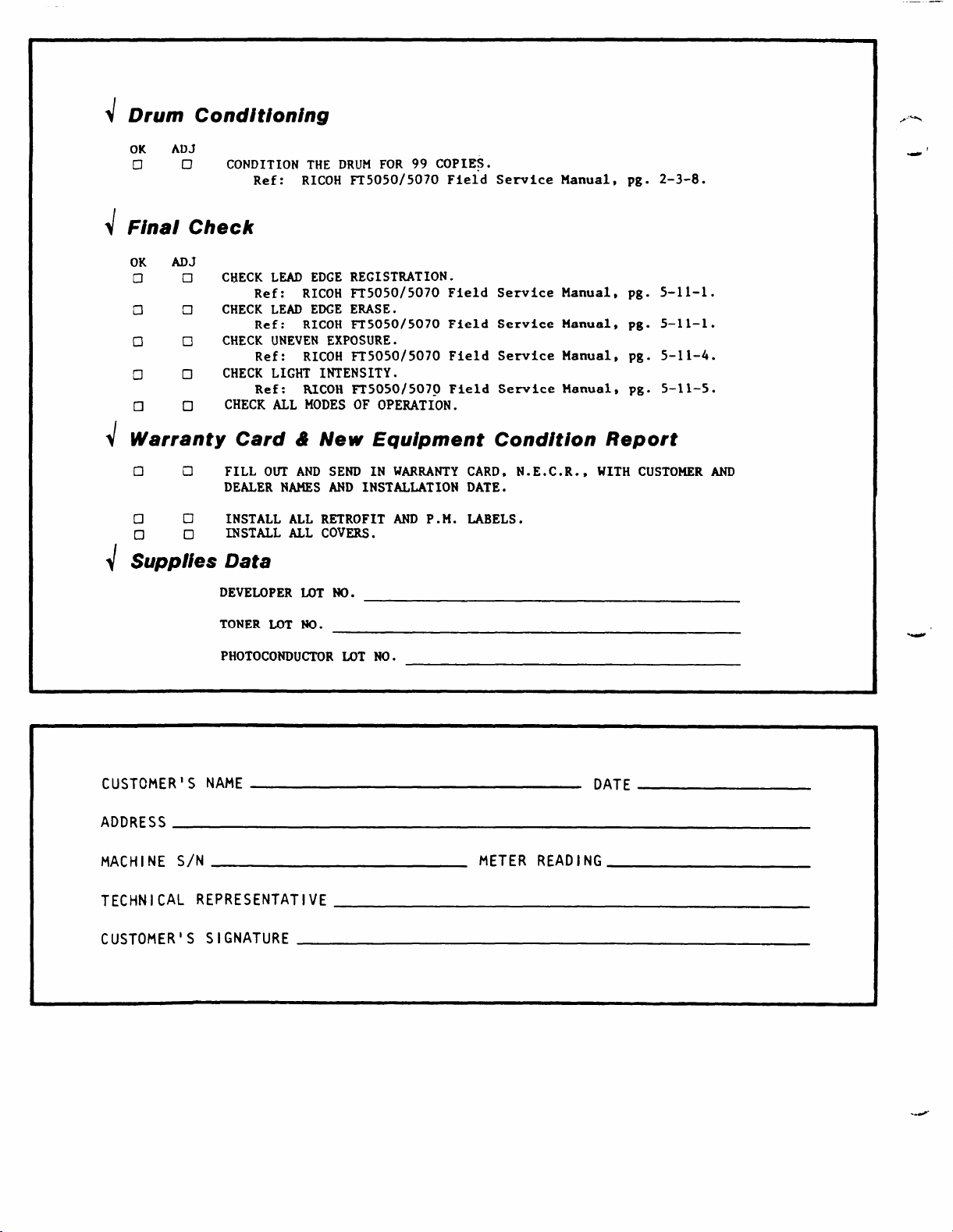
rum Conditioning
~D
OK ADJ
CID
Final Check
~
OK ADJ
c1
a •1
00
00
❑ 0
arranty Card & New Equipment Condition Report
Jw
no
•1
Lppies Data
d
CONDITION THE DRUM FOR 99 COPIES.
Ref: RICOH FT5050/5070 Field Service Manual, pg. 2-3-8.
CHECK LEAD EDGE REGISTRATION.
•1
c1 INSTALL ALL RETROFIT AND P.M. LABELS.
Ref: RICOH FT5050/5070 Field Service Manual,
CHECK LEAD EDGE ERASE.
Ref: RICOH FT5050/5070 Field Service Manual,
CHECK UNEVEN EXPOSURE.
Ref: RICOH
CHECK LIGHT INTENSITY.
Ref:
CHECK ALL MODES OF OPERATION.
FILL OUT AND SEND IN WARIW4TY CARD, N.E.C.R., WITH CUSTOMER AND
DEALER NAMES ANI) INSTALLATION DATE.
INSTALL ALL COVERS.
DEVELOPER MIT NO.
RICOH ~5050/5070 Field Service Manual,
FT5050/5070 Field Service Manual, pg. S-11-4.
pg. 5-11-1.
pg. 5-11-1.
pg. 5-11-5.
TONER LOT NO.
PHOTOCONDUCTOR LOT NO.
CIJSTCMER’S NAME
ADDRESS
MACHINE S/N
TECHNICAL REPRESENTATIVE
CUSTOMER’S SIGNATURE
I
I
DATE
METER READING
../
Page 19
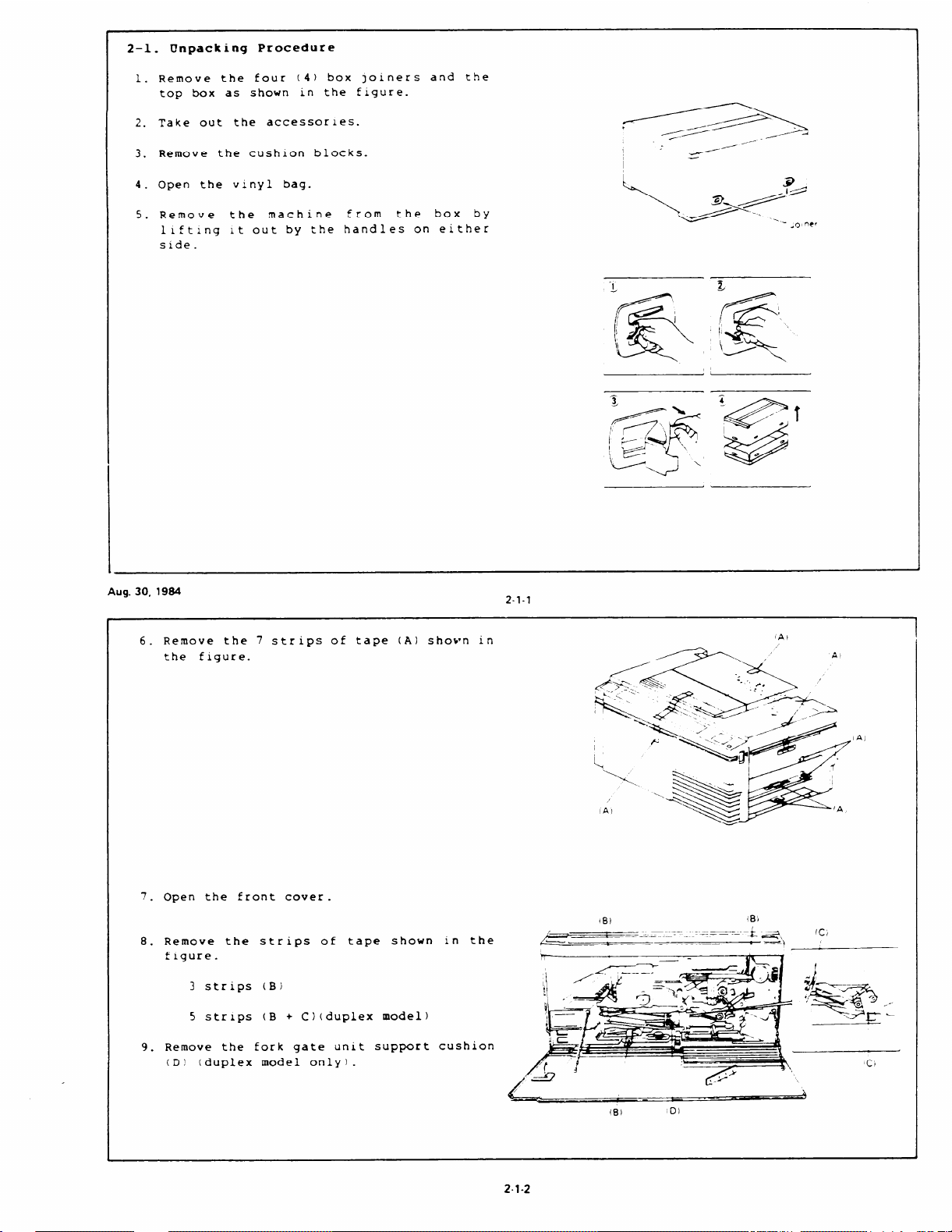
Unpacking Procedure
2–1.
1.
Remove the four (4) box ]olners and the
top box as shown in the figure.
2.
Take out the accessories.
Remove the cushion blocks.
3.
4.
Open the vinyl bag.
t
~
.-
_.
----’
___
5.
Remove the machine
llftlng lt out by the handl
side.
Aug.30,1984
Remove the 7 strips of tape (A) shotrn in
6.
the figure.
from
the box by
es on either
. . .
z-l-l
/’—9—.. .’
IAI
A
7.
Open the front cover.
8.
Remove the strips of
figure.
3 strips (B)
5 str~ps (B + C) (duplex model)
Remove the fork gate unit support
9.
(D! (duplex model only).
2-1-2
‘\.
IA)
h
\
—
——— —
—
— -k
—- m~
a,
--)
(c,
.
Page 20
--. --,..-,
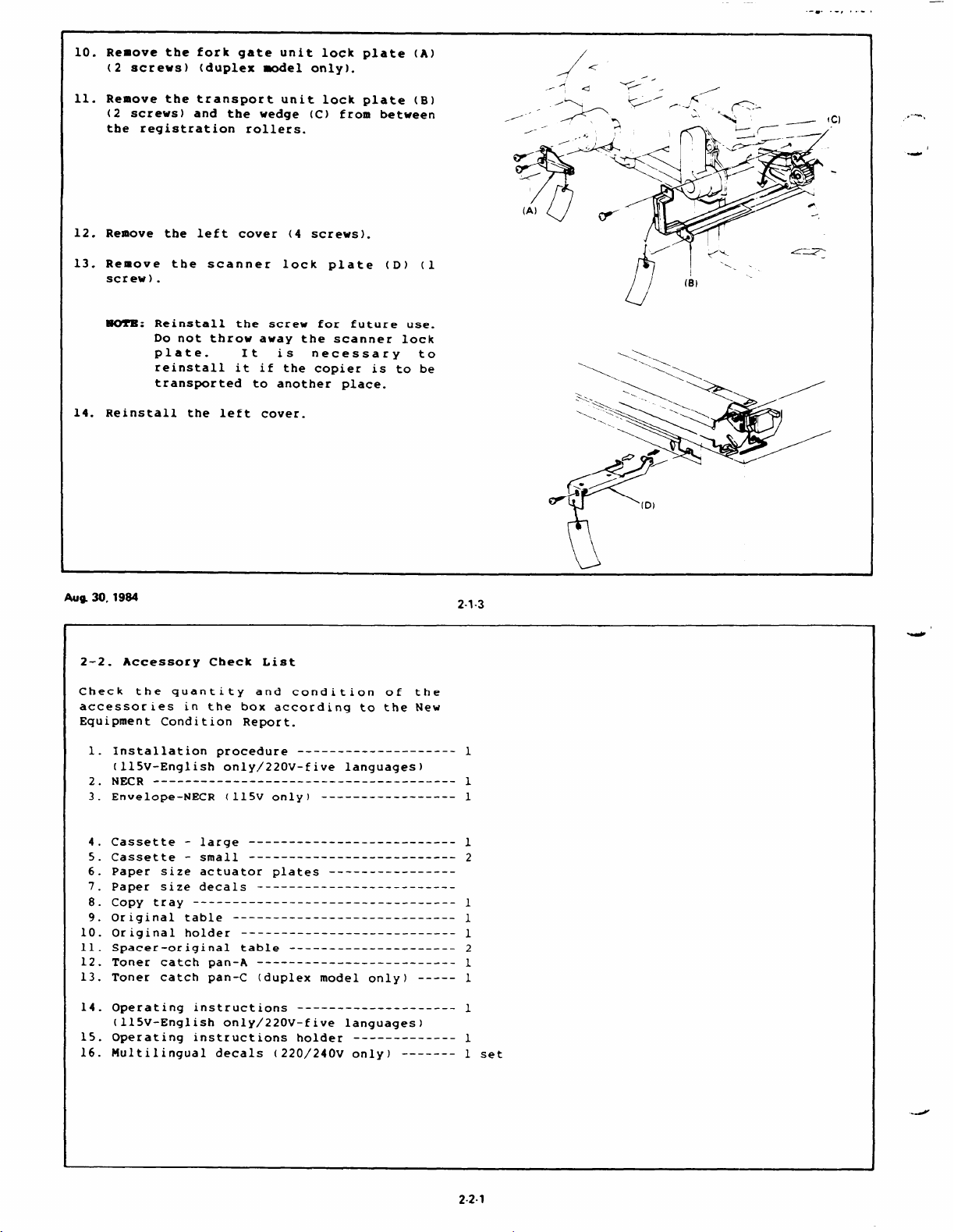
Remove the fork gate
10.
(2 screws) (duplex model only).
11.
Remove the transport unit lock
(2 screws) and the wedge (C) from between
the registration rollers.
12.
Remove the left cover (4 screws).
13.
Remove the scanner lock plate
screw) .
WU1’B: Reinstall the screw for future use.
14.
Reinstall the left cover.
Do not throw away the scanner lock
plate. It is necessary to
reinstall it if the copier is to be
transported to another place.
unit lock plate (A)
plate (B)
(D) (1
./
A
.=l~
<
-.
-< .
u
/
c)
,-%,
.4
1
AUQ 30,1984
2-2. Accessory Check List
Check the quantity and condition of the
accessories in the box according to the New
Equipment Condition Report.
Installation procedure
1.
(l15V-English only/220V-five languages)
--—_ ___________________ _______________
NECR
2.
Envelope-NECR (115V only)
3.
Cassette - large
4.
Cassette - small
5.
Paper size actuator plates
6.
7.
Paper size decals
Copy tray
8.
Original table
9.
10.
Original holder
11.
Spacer-original table
12.
Toner catch pan-A
13.
Toner catch pan-C (duplex model only)
----------- ____ ________ ________ __
-------- __________________
--__— __________ ________ ---
---------- ___________ _______
---- ________ ______ ______ ___
-------- --------- .-.
---------- -------
----- -----------
------ _________ ____ ______
------ ________ ---_-_—
______________________ ___
-----
(7
2-1-3
1
1
1
1
2
1
1
1
2
1
1
14.
Operating instructions
(l15V-English only/220V-five languages)
15.
Operating instructions holder
16.
Multilingual decals (220/240v only) ------- 1 set
----- ________ -------
------ -------
1
1
I
2.2.1
Page 21
..-,,
---
2-3.
Installation Procedure
1. Check and adjust the machine level.
2. Open the front cover and pull out the
fusing unit.
3.
Remove
screws) and the oil pad pressure plate
(B).
4.
Remove the oil supply pad (C) andconflrm
that the oil blade 1s free from foreign
matter .
5. Saturate the oil supply
silicone oil (D).
6.
Reassemble and return the fusing unit
to Ats original position.
the fusing unit cover
(A) (2
pad with
gar
.
.
..,~%
P
~ ,2A
t
,\
J >’ d
c’
.—-
,J= “a
f /-j-3
------
AD)
May 7,1984
7.
Fill the oil tank (A) with silicone oil
(B)(maximum capacity
Remove the rear cover (2 screws)
8.
Remove the coollng fan (C)(2 screws and 1
9.
connector) and swing the optics board (D)
out to the right (1 screw). Take care not
to damage any harnesses or connectors.
10. Manually operate the oil pump solenold
(E)
and confirm proper operation and
condition of silicone 011 supply system.
1.6 liters).
2-3-1
(A)
11. Return the optics board and reinstall the
cooling fan and the rear cover.
harness must be returned to its original
Position.
The wire
)
.
t!’
2-3-2
Page 22
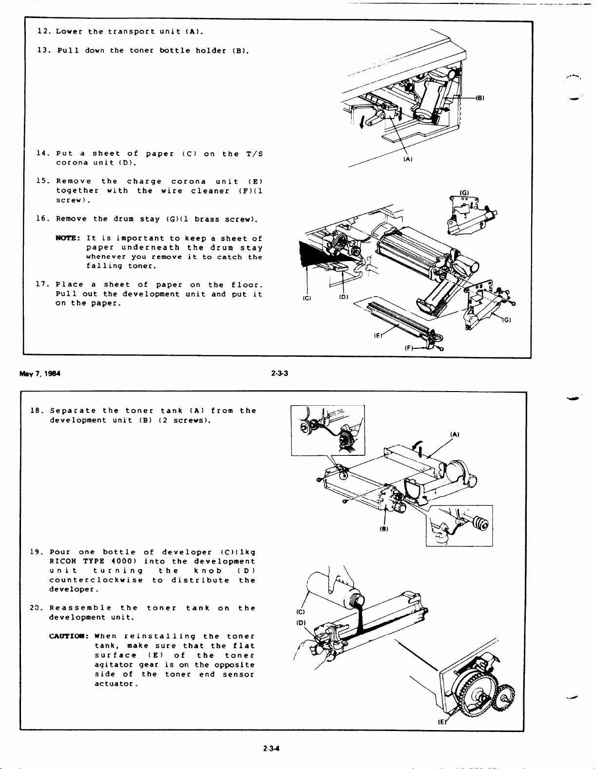
12. Lower the transport unit (A).
13. Pull down the toner bottle holder (B).
14. Put a sheet of paper (C) on the T/S
corona unit (D).
1S. Remove
together with the wire cleaner
screw) .
16. Remove the drum stay (G)(l brass screw).
the
charge corona
unit (E)
(F)(l
—.
/ ‘A)
— .—. —...—,.—
NOTB: It is important to keep a sheet of
paper underneath the drum stay
whenever you remove it to catch the
falling toner.
17. Place a sheet of paper on the floor.
Pull out the development unit and put it
on the paper.
M8y 7,1904
18. Separate the toner tank (A) from the
development unit (B) (2 screws).
2-3-3
19. Pour one bottle of developer (C)(lkg
RICOH TYPE 4000) into the development
unit turning
counterclockwise
developer.
20. Reassemble the toner
development unit.
CAUTICX@: When reinstalling the toner
tank,
surface
aqitator gear is on the opposite
side of the toner end sensor
actuator .
make sure that the flat
the knob (D)
to distribute the
tank on
(E) of
the toner
the
2-3-4
Q-i
J
Page 23
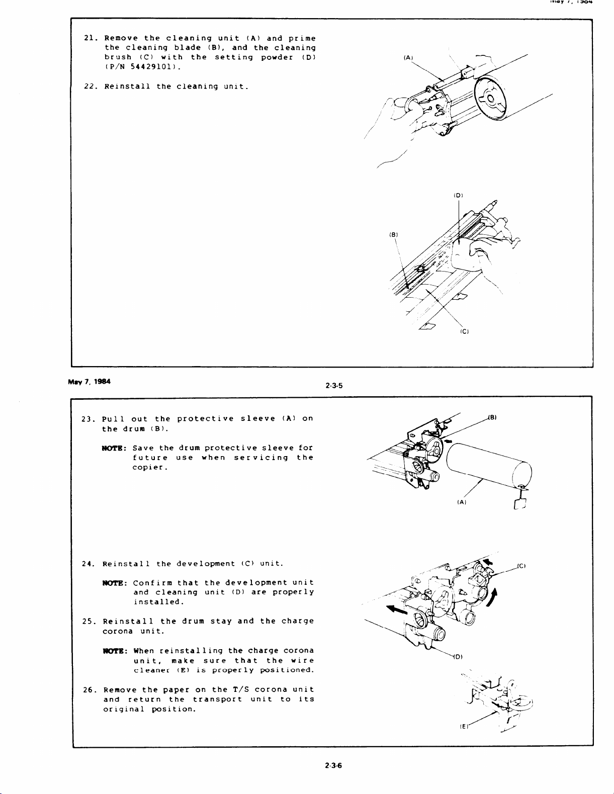
21. Remove the cleaning unit (A) and prime
the cleaning blade (B), and the cleaning
brush (C) with the setting powder
(D)
(P\N 54429101).
22. Reinstall the cleaning unit.
(A)
P
,, ,
,-
,/
/
Mav 7,1984
23.
Pull out the protective sleeve (A) on
the drum (B).
NOTB: Save the drum protective sleeve for
future use when servicing the
copier.
2-3-5
(B)
\
/4
/.//
/2
.2’
\
‘\
(c)
(A)
24.
Reinstall the development (C) unit.
lJOl’E:Confirm that the development unit
and cleaning unit (D) are properly
installed.
Reinstall the drum stay and the charge
25.
corona unit.
I@iY?15:When reinstalling the charge corona
unit,
make sure that the wire
cleaner (E) is properly positioned.
Remove the paper on the T\S corona unit
26.
and return the transport unit to its
original position.
I
/.
2-3-6
Page 24
27. Remove the toner tank plug (A) and load
the toner bottle onto the bottle holder
and raise the holder
bracket.
NOTE 1: For loading the toner bottle (C),
refer to the decal attached on
the inside front cover.
(B) up to the
I
. ...
-(A)
--
Aug.30,1984
28.
29.
~ 2: Confirm that the toner bottle
gear
trying to rotate it.
toner bottle gear is properly
engaged,
not rotate freely.
Remove the misfeed location indicator
panel (A)(l screw).
Turn on SW1 of DIP switch
front cover.
~: In 240V areas,
transformer modification must be
done at this time.
is properly engaged by
When the
the toner bottle does
and close the
the 220\240v
“4
a..
OIP <W,l CU
.!_ :-;_y4 S_*
ikmw!
1 23 45 6
Im
. v. u--—.—_
<!%
‘@.*aQ
.T
%
‘ “+%< g
Q
[FT5070)
,/
/“
/
30.
Lower the platen cover.
31.
Plug in the machine and
switch.
32.
After warm up period is
99 and press the Print key for drum
conditioning.
33.
After the machine stops,
main switch.
34.
Turn off SW1 of DIP switch and reinstall
the misfeed location indicator panel.
turn on the main
completed, enter
turn off the
2-3-8
---- s--..
1 NOT USED
6 18EEPER ON
I
]COWNT UP
]BEEPER OFF
---- .
.—
.J
=3
-/’
Page 25
Install toner
35.
catch pan-c (A) on the
transport unit (B) (1 screw )(duplex model
only) .
Install toner catch pan-A (C) on the drum
36.
stay (1 screw).
190’1’11:This catch pan is optional because
Aug. 30, 1984
Close the front cover.
37.
Install the original table (A) using the
38.
spacers (B) provided.
it hinders drum stay removal. To
remove a drum stay fitted with this
catch pan: remove the toner bottle,
lift up the bottle holder
(D), and
then remove the drum stay.
(r’
2-3-9
39.
Install the original holder (C) on the
platen cover as shown.
40.
Install the copy tray and load paper into
the cassettes.
41.
Check machine
Fill out the
42.
Report
(NECR)
operation and copy quality.
New
Equipment Condition
2-3.10
Page 26
May 7,Iw
.—_—
2-4
.
Cassette Modification
Take off the cassette cover.
1.
Remove the side fences (A) (1 screw each)
2.
and the bottom plate (B).
Reposition the rear fence (C) in the
3.
desired paper size position (1 screw).
19tEFB:Paper size positions are shown on
the inside of the cassette.
Reinstall the bottom plate.
4.
Reinstall the side fences in the desired
5.
paper size position.
Attach the proper paper size decals (D)
6.
on the cassette at the positions shown.
7.
Insert the desired actuator plate (E) in
the slot on the front of the cassette as
shown.
(A)
1?
M8y7, 1984
2-5. Key
MY1’E:
1.
Lowe r
Remove the right front cover (2 screws)
2.
●nd right inner cover (3 screws).
Remove the cover plate (A) and fixing
3.
plate (B) from the key counter bracket
(c).
4.
Hold the fixing plate on the inside of
the key counter bracket and insert the
key counter holder
Counter Holder Installation
Three
recommended for this copier (Ricoh,
Recon, and Rengstler
When installing the Hecon, or
Hengstler
to make wiring by referring to
figure at the right.
the front cover (2
types of counters
key counters).
counters, it is required
thumb screws).
(D).
are
the
241
E!za
2-5-1
Page 27
5.
Align the holes in the fixing plate with
the mounting holes of the key co~nter
holder and secure the key counter holder.
.,-r.,--- -
FKYl”B:The fixing plate has three sets of
holes. Make sure to use the holes
that match the type of counter when
installing.
6.
Remove the shorting plug (F) from the key
counter connector (G).
NOTB: This shorting plug is usually on
the harness.
7.
Plug in the key counter harness (H).
8.
Reassemble the copier.
Insert the key
counter and check its operation.
May 7,1904
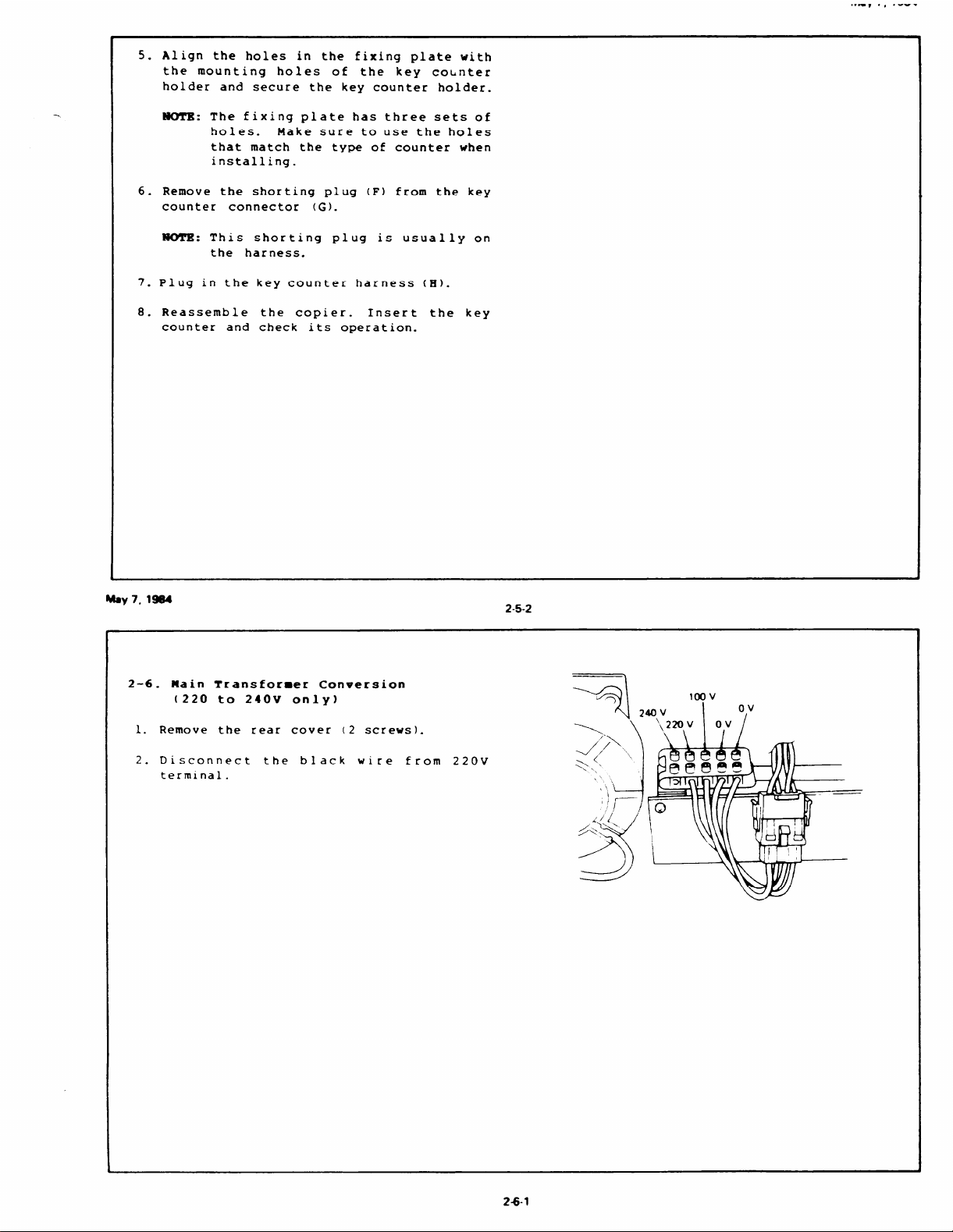
2-6. Main Transformer Conversion
(220 to 240v only)
1. Remove the rear cover (2 screws).
2.
Disconnect the black wire from 220v
terminal.
2-5-2
26-1
Page 28

—————
.... ..—.
--.,
‘
%-
Page 29
SECTION 3
PREPARATION FOR
TRANSPORTING COPIER
Page 30

-. —
Page 31

may 1, 1YU4
PRBPAIWTIOU FOR TW13SPORTIBJG THE COPIBR
Before moving the copier from its place of
installation,
transportation as follows below.
The copier may be badly damaged if it is
moved without proper preparation.
1.
Remove the developer
development unit.
Insert the drum protective sleeve.
2.
3.
Reinstall the development unit.
4.
Reinstall the drum stay and the charge
corona unit.
5.
Place a wedge between the registration
rollers.
Install the transport unit lock plate and
6.
the release lever lock plate.
7.
Install the fork gate unit lock plate.
(FT5070 only)
be sure to prepare it for
from the
1 ,6
,-”4
/
Fork GateUnit Lock Plate
v<”, /
‘/--’ /\
/ \ “’’”
$
u
Trans~rt’Unlt Lock Plate
1
-.,
.-’
\
L.A
.
May 7,1984
8.
Remove the left cover and insert the
scanner lock plate.
?WTll: Confirm that the scanner is at the
9. Secure the front cover, platen cover and
by-pass table with tape.
CAUTION: While transporting the copier by
home position.
car, always cover the copier to
avoid direct sunshine.
leave lt in the car or expose it
to extreme hot or
conditions.
Do not
cold
3-1-1
\“
(+
‘i Scanner Lock plate
\
\
\
3-1-2
Page 32

Page 33

SECTION 4
REMARKS
Page 34

.Ud#”
e“
’984
Page 35

4-1. Points to Remember
CAOTIU9: Keep hands away
●
This is to avoid possible injury when the copier starts idling at the end of warm
from mechanical drive cqnents when the copier is warming up.
up.
●
The beeper sounds five times just before starting idling.
Drum Charge
1. The corona
dry cloth.
2.
Do not touch the corona wires with oily hands.
wires should be cleaned at every service call by sliding the corona unit or with
Do not use emery paper or any solvent for wire cleaning.
3. Make sure that the corona wires are correctly positioned between the cleaner pads.
4. After cleaning the charge corona unit,
make sure that there are no threads on the casing to
avoid white lines on the copy.
Rxposure
1. Do not adjust the following parts:
a: First and second scanner height
adjusting cams (1 screw each)
b: Scanner Guide Plate (3 screws)
c: Lens Axis Adjusting
Cam (1 screw)
d: Lens Position Adjusting Screws
e: Fourth Mirror Angle Adjusting Screw
f: Lens Home Position Sensor (1 screw)
May7,1984
4-1-1
2. Lens home position sensor does not have a convenient ad]usting procedure.
sensor,
mark the position of the sensor bracket before removing it, and adjust the fine
position of the sensor by checking the copy image (horizontal magn~fication and focus).
3. Do not bend or damage the lens support plate or the mylar strip.
4.
Launa 011 or an equivalent oil should be used to lubricate or clean the following:
a. Scanner Gu~de Rod (cleanlng)
b. Scanner Guide Rod Pads (Lubrlcatlon)
c. Scanner Guide Plate (Lubrlcatlon,/Cleanlng )
CAUTION : Do not use slllcone 011 or any other kind of oil.
5. Clean the exposure glass with alcohol and water.
6. Clean the mirrors only with alcohol and,’or water and a soft cloth.
7.
Do not touch the followlng parts with bare hands:
a.
Reflectors
b. Exposure Lamp
c. Mlrros and Lens
8. Do not ad]ust the VR on the optics board.
9.
When ad)ustlng the light lntenslty, make
ten copies before proceeding to check copy image ~f
the main switch has lust been turned on.
When replacing the
4-1-2
Page 36

Development
1. Be careful not to nick or scratch the development roller sleeve.
2. Place a sheet of paper under the development unit when it is out of the copier.
-—.
3. Clean the suction duct at every EM or PM.
4. Clean the development unit guide plate before reinstalling the unit.
5. When reinstalling the toner tank to the development unit,
make sure that the flat surface of
the toner agitator gear is on the opposite side of the toner end sensor actuator.
Toner
Image density sensor should be cleaned at every EM or PM with a blower brush.
1.
2. DO not touch the sensor pattern with bare hands.
3. Image density sensor adjustment is required when:
a: The ID sensor board is replaced.
b: The main board is replaced.
c: The drum has been replaced and Vsg is out of standard.
d: Problems with toner supply have occurred and ID sensor check shows the Vsg to be out of
standard.
4. Grease the toner supply clutch with Mobil Temp 78 periodically to avoid noise and bad
operation.
.dO,’
May7,19$4
4-1-3
Transfer and Separation
1. The corona wires should be cleaned with a dry cloth at every EM or PM.
2. While the drum stay is out,
do not lift up the corona unit.
(The corona casing hits against
the drum.)
Cleaning
DO not damage the edge of the cleaning blade.
1.
2.
DO not touch the cleaning brush with oily hands.
Before pulling out the cleaning unit,
3.
4.
Be careful not to damage the drum with the pick-off pawls when pulling out or inserting the
place a sheet of paper under it.
unit.
When a new cleaning blade and/or a new cleaning brush is installed,
5.
dust them with setting
powder before reinstalling the unit.
.-
4-14
Page 37

Pusing
1. When removing the fusing unit, keep it in an up-right position so that the silicone oil does
not spill.
2. After replacement of the oil blade, oil supply pad, and the hot roller, prime with silicone
oil to the top of the OL1 blade.
3. Be careful not to damage the edge of the hot roller strippers or their tension springs.
4. Be careful not to bend the pressure roller strippers.
5. DO not touch the fusing lamp with bare hands.
6. Be sure that the fusing lamp is not in contact with the inner surface of the hot roller.
7. Be sure that the oil end sensor contacts the bottom of the oil tank.
8. When replacing a fusing temperature control board, make sure that the DIP switch on the board
is set for the correct frequency (50/60Mz).
Mav 7,1984 4-1-5
Paper Feed and Duplex
1. Grease the following parts with Mobil Temp 78 periodically to avoid noise and bad operation:
a. Slip clutches in upper, lower,
b. Worm Gears and Worm Wheels of upper and lower lift motors.
2.
Be careful not to damage the forks when removing the fork gate unit.
3. The rollers and S1lP clutch for duplex and cassette feed are not Interchangeable.
4.
Be sure that the duplex transport belts are matte-side out when replaclng them.
5. When reinstalling the support bracket,
the groove of the registration clutch stopper.
Optional Equipments
1. When servlclng the document feeder and/or sorter,
copier
1s off.
2. Before servlclng the large capacity tray,
and duplex separation rollers.
make sure that the bracket is properly engaged with
make stire that the Main switch of the
unplug the power supply cord of the tray.
4-1-6
Page 38

4-2. Handling the Drum
1. Never touch the drum surface with bare hands.
2. Store the drum in a cool dry place away from heat.
Illdv /, lYd4
3. When cleaning the drum, always use a pair of gloves.
cleaning.
Bring it back to the service depot for disposal according to local regulations.
Do not throw away cotton used for
4. Always prime the drum with setting powder after cleaning the drum, and when installing a new
drum. This should be done within one minute in a location not exposed to room light.
5. To protect the drum,
always applly setting powder to a new cleaning blade and/or a new
cleaning brush before installing them.
6. Drum conditioning is necessary when a new drum is installed. In addition, it should be done
at the following times:
1) When image density is reduced due to over-exposure of the drum.
2) After cleaning the drum.
3) When the drum is lightly scratched.
7. Always keep the drum in the protective sleeve when inserting or pulling the drum out of the
copier (except when applying setting powder).
8. Before inserting or pulling out the drum,
the cleaning unit should be pulled slightly out to
avoid drum damage by the pick-off pawls.
9. Before inserting the protective sleeve on the drum while it is in the copier, always take out
the development unit.
If the sleeve is inserted while the development unit is ir,the copier,
the edge of the sleeve will scrape off developer from the development roller.
10. Send used drums to the distributor according to standard procedure.
4-2-1
Page 39

SECTION 5
REPLACEMENT AND ADJUSTMENT
Page 40

— —
Page 41

1-1.
Bxposure Glass Removal
Take off the left scale (2 short screws).
1.
2.
Grasp the left edge of the exposure glass
and lift it up slightly.
edge
holder.
out from under the right glass
Remove the exposure glass.
Slide the other
-,. . .-”.
ShortScrew
NoTB:
When reinstalling the exposure
glass:
●
Make sure that the left edge of the
glass is flush with the sensor
pattern plate.
●
Make
sure that the right glass
holder firmly secures the exposure
glass.
sensor Pattern Plate
5-1-1
May 7,1984
1–2. Original Size Indicator Board Removal
1.
Turn off the main switch.
Take off the left scale (2 short screws).
2.
Remove the platen cover and the mounting
3.
studs.
4.
Remove the upper cover
(2 long and 6
standard screws).
5.
Open the front cover and remove the left
inner cover (4 screws and 1 thumb screw).
6.
Remove the orlglnal size indicator board
(1 connector).
&
Original Size
Lefl Inner Cover
Left Scale
I
*
Ill
Platen Cover
. 1A
5-1-2
Page 42

———
Iwdy t, Iyoq
1-3.
2nd Mirror Removal
IiOTB: This procedure is usually performed
in order to make cleaning the 3rd
mirror easier.
1.
Turn off the main switch.
2.
Remove the exposure glass.
(See Exposure
Glass Removal.)
3.
Move the 1st scanner 2/3 to the right by
pushing it at the rear side.
4.
Remove
depressing
the front spring plate by
the top of the spring and
moving the plate towards the front side
of the machine.
5.
Carefully pull the 2nd mirror towards the
front side of the machine to remove the
rear spring plate.
6.
Lift the mirror out of the machine rear
side first.
7.
Clean mirrors with alcohol followed by
water, and then dry.
[Front]
2nd Mtrror
Rear Spmg Plate
d’
- To Reinstall -
8.
Place the rear spring plate in place and
hold it with your finger.
9.
Insert the 2nd mirror into the front side
plate cut out.
10.
Insert the rear side of the mirror into
the rear spring plate.
11.
Locate the bottom of the front spring
plate and rotate the top of the spring
into position.
t90TB: Make sure that you install the
mirrors with the 1st surface facing
the lens as shown.
5-1-3
(Right)
! ~ti=&;
~—_J
““’at’?~’rs’ea~~’n’
I
surface
1St
(Wrong)
,2nd%anner&xket
May7
19a4
5-14
‘d
I
Page 43

1-4. Exposure Lamp Replacement
1. Turn off the main switch.
2. Remove the exposure glass. (See Exposure
Glass Removal.)
Move the first scanner to the position
3.
where the rear frame is cut out.
4. Remove the reflector cover (2 screws).
5. Wrap a strip of paper around the exposure
lamp as shown.
CAUTION: Do not touch the reflector or
the new exposure lamp with your
bare hands.
paper as shown.
Use a strip of
(Finger oil
marks on the lamp or reflectors
will be affected by the heat and
will result in discoloration.)
Reflector Cover
iExposure Lamp
Press the release lever on the front lamp
6.
terminal as shown and take out the lamp.
.Install
7.
paper .
a new lamp US111C3 a strip of
(Set the rear terminal first. )
NOTE: The blister on the lamp must point
toward the mouth of the reflector
as shown.
8.
Check the exposure lamp posltlon and the
liqht
intensity
(See
Exposure
Posltlon and Light Intensity Adjustment.)
Lamp
5-1-5
May7,1984
, Reflector Cover
5-1-6
Page 44

1-S. Exposure Lamp Position
Remove the exposure glass. (See Exposure
1.
Glass Removal. )
-Horizontal Adjustment-
2.
Move the exposure lamp to the center of
the copier.
3.
View the lamp filament through the sight
holes on the top of the reflector cover.
The filament should be directly beneath
the sight holes.
4.
To correct the position of the filament,
turn adjusting screws.
-Vertical Adjustment-
5.
Move the exposure lamp fully to the
right.
View the lamp filament through the
6.
ventilation
the upper cover.
slits on the right side of
The filament should be
level with the sight holeson the sideof
the reflector.
7.
To correct the position of the filament,
remove the platen cover and the upper
cover (8 screws and 2 mounting studs).
8.
Remove the reflector cover (2 screws) and
turn the adjusting
knobs until the
correct position is achieved.
~: Be sure to tighten the adjusting
knob screws after adjusting the
lamp position.
9. Check uneven exposure and light
intensity. (See Copy Image Section.)
5-1-7
Adjusting Knob ‘
/
=1
Adjust Ing Screw
May7 1984
5-1-8
Page 45

Scanner Drive Wire Replacement
1-6.
1. Turn off the main switch.
MaInBoard
1
2. Remove the platen cover,
studs,
3. Remove
and the
4.
Remove
cooling
5. Move the harnesses out of the way of the
bottom of the optics board (1 twist
clamp).
right (1 screw) and the main board to the
left (2 screws).
6. Loosen the wire clamp screw.
7.
Move
pos~tlon.
8. Unhook the tension spring and take off
the wire hook.
and the upper cover
the left scale (2 short screws)
exposure glass.
the rear cover (2 screws) and the
fan (2 screws and 1 connector).
Swing the optics board to the
the 2nd scanner to the return
Take OUY the old wire.
the mounting
(8 screws).
Scanner Drive pulley ~lre Clamp
Tension Spring
9. Remove the 2nd scanner drive pulley (1
Allen screw) by aligning the notch of the
pulley d~sk
position sensor.
10. Position the bead of the new wire on the
groove of the 2nd scanner drive pulley
and wrap the wire around the pulley with
two and half turns as shown.
11. Secure the turns of the wire on the
pulley with the ‘Jclamp (or with tape).
12. Set the 2nd scanner drive pulley on the
drive motor shaft as shown and t~ghten
the Allen screw on the flat side of the
shaft.
?un’E: ‘
●
with the 2nd scanner home
The end of the second scanner
drive pulley should be flush
with the end of the motor shaft.
The 2nd scanner home position
sensor should be positioned
between the short and long ends
of the wire.
5-1-9
second
Drive
May 7,
1984
Long
End
Second Scanner
. . -..,
.
’’’---
Drive Pulley
,
I
‘...%
4
----
\
- -.
-..
‘---
.-..
‘---
:\
“&’
5-1-1o
:A*~ati
Yi&2~b”
Long End
Second &ner ~
Home position Sensor :,:.
I
Page 46

13. Run the scanner drive wire over the
pulleys in the follow;ng order:
1 Short end should be in lower track
(WPl). (Tape the wire on the bracket. )
2 Long end should be in upper track (wP1)
3 Outer track (WP2)
4 Outer track (WP3)
5 Lower side (Wire Clamp)
6 Lower track (WP4)
7 Lower track (WPS)
8 Three and half turns from lower to
upper (Scanner Drive Pulley)
9 Upper track (WP5)
10 Lower track (wP6)
11 Inner track (WP3)
12 Inner track (WP7)
14. Remove the tape and pull the ends of the
wire together and join them with the wire
hook .
15. Push the tension pulley to the right.
Take the wire off of the pulleys in
figures 2 (WP1) and 9 (WP5) of step 12,
so that you can hook the tension spring
easily.
16. Hook the tension spring and reposition
the wire on the pulleys in steps 2 and 9 .
.,----
.-,’
5-1-11
Wire Clamp
WP3 (2nd Scanner Pulley)
10
c1
*
WI%
El
M8y7, 1984
WP6
WP2
5-1-12
L
WP7(Tens,oo Pulley)
J
Page 47

17. Remove the Q clamp.
18. Rotate the scanner drive pulley and make
sure that the scanner drive wire moves
smoothly and
there is no overlapping
around the scanner drive pulley.
WUI’B: Step 18 is
overlapping of the scanner drive
wire occurs,
A3 (11” x 17”) copies may be
reduced.
Amportant!
If
then the trail edge of
5-1-13
May 7,1984
– Rough Adjustment of Wire Clamp Position -
Move the 2nd scanner to the right (rear
19.
view)
and position it so that
the
distance between the 2nd scanner bracket
and the inner
surface of the optical
frame 1s 52mm (2.05”).
Move the first scanner to the home
20.
posltlon and make the right edge of the
wire clamp flush with the right side of
the home Position sensor.
Tighten the screw of the clamp temporarily.
21.
Ad]ust the horizontal magnification by
22.
changing the wire clamp posltlon. (See
Horizontal Magnification Adjustment.)
Wire Clamp,
—----/,” ;
.—
—++ ‘J
/
~- t+ome Position Sensor
/’
W,re Clamp
hd Scanner
Bracket ‘.
\-
‘--,
~.G6
%*
/< ,
,
— ,—Y
Flush
‘=/’ ‘<
\
T “;
\
‘ ~!.”””;.
‘./’=
~ @</’-
.
.4
NOTE lnner%rf~
I
I
I
“>(
—,. —
/
c
—P
Opticai Frame
(205”)
5-1-14
Page 48

—
1-7
. Scanner Drive Motor Replacement
..-
1.
Remove the
platen cover and the mounting
studs.
2.
Remove the upper cover
(8 screws) and the
rear cover (2 screws).
3.
the three scanner
Fix
as shown,
to hold the
pulleys with tape,
scanner drive wire
on the pulleys.
4.
Lift up
the scanner drive pulley
vertically and take it off from the shaft
of the scanner drive motor
(2 Allen
screws) .
5.
Disconnect
connectors and free them from
motor bracket.
6.
Remove
the
two scanner
scanner
the
drive motor (4
the scanner
screws) .
7.
Install a new scanner drive motor.
NO’TB: When installing the scanner drive
pulley on the motor shaft:
●
Make sure that one of the allen
screws is secured squarely on
the flat side of the motor
shaft.
motor
Scanner Drive
Motor
*
The scanner drive pulley should
be flush with the ‘>nd of the
motor shaft.
8. Remove tapes and make
scanner
drive wire is correctly
positioned on the pulleys.
sure that the
5-1-15
May 7, 1984
5-1-16
Page 49

May 1, 1354
l–8. Lens Drive and 2nd Scanner Drive Motor
Replacement
1.
Remove the platen cover and the mounting
studs.
2.
Remove the upper cover (8 screws) and the
rear cover (2 screws).
3.
Remove the left scale (2 short screws)
and the exposure glass.
4.
Remove the cooling fan (2 screws and 1
connector) .
5.
Move the harnesses out of the way of the
bottom of the optics board (1 twist
clamp). Swing the optics board to the
right (1 screw).
,,-
2nd Scanner
Drwe Puliey
1
Disconnect the two
6.
motors
screw) .
7.
Move the scanner to the return position
and put the Slclamp (or tape) on the 2nd
scanner drive pulley.
Flx the pulley (WP1) with tape as shown.
8.
9.
Loosen the Allen screw on the 2nd
drive pulley and align the notch of the
disk with the 2nd scanner home position
sensor .
10.
Take off the 2nd scanner drive pulley
from the motor shaft.
11.
Open the front cover and take out the
fusing unit (1 lock pin - orange).
Take out the motor
12.
13.
Remove the motor cover (1 screw) from the
motor
and remove the nylon clamp (1
assembly.
connectors of the
assembly (3 screws).
scanner
5-1-17
Motor \
Second Scanner
Drwe Motor
‘ear \ e
*B
‘-.
4% .
.
y+
I
/
‘%
AL
Coollng Fan
M8y 7,1984
9
“ ‘- --’---’
Loosen the Allen screw of the motor gear
14.
on the motor shaft.
from the assembly --- lens drive motor
and/or
screws each).
2nd scanner drive motor --- (2
Remove the motors
5-1-18
&&i!ii!i!6
k
&
>
‘\\
II
‘1.
MotorGver
Lens Drive
Motor
“&V.A
=&
Page 50

May 7,1984
15. Install the new motor in the motor
assembly.
Make sure that the harnesses
CAUTION :
*
are properly positioned.
—
* When installing the motor
gear, push the gear against
the motor and then
Allen screw on
secure the
the flat
surface of the motor shaft.
When installing
*
scanner motor,
drive gear so
rotate
that the flat
the
2nd
the
side of the shaft faces the
rear of the copier.
16. Reinstall the motor assembly and
reassemble the copier.
CAUTIOU: When installing the 2nd scanner
drive pulley, make sure that the
notch of the 2nd scanner drive
pulley faces the right rear
corner of the copier.
P
i/
//
2nd &ner
Home?osmon%nsor
s:tt
[Rear]
[Front]
2nd Scanner
Drive Pul[eY
5-1-19
‘-
d
Page 51

SECTION 6
SERVICE TABLES
Page 52

.-J
4
Page 53

6-1. ADJUSTMENT TABLE
[COPIER]
,.oa, ,, ,-
No.
Adjustment Item
Development Roller Magnet
Angle
1
Doctor Gap
2
Adjustment Standard
1 line right of center {Move the plate to the
left and then move it back.)
1.26 t 0.1 mm (0.050” t 0.004”)
~
ltne RIO( of Center
1
Doctor Gap
Plate
Nota
Magnet A@e
Ad~sting Rate
No.
Toner Supply Clutch
3
Image Density Sensor
4
Adjustment Itam
Adjustment Standard
O 1 mm (0.004”)
LIw *P gauge (P/N 52059101).
Grease with Mobil Temp 78
(P/N 54479078).
+4 ? 0.2 v
6-1-1
Olmm
Gao Gauge
!
I
u
ChamferedEnd
Toner Supply Roller
Drwe Sprocket
E rlnq
L
I
.“
lb
DqItaI
Multlrneter
r-—a I
:1Ilon
6-1-2
pyz~
A-’
I Po51twe Probe
Page 54

.—— — .. ----
—
——.
.- e..-,.- -.
.—.
No.
5
6
Adjustment Item
Feed Clutches
Pressure Springs
(Fusing Unit)
I
0.1 mm (0.004”)
Use
Lock nut should be flush with the end of
the adjusting screw.
[Nip Band Width]
Adjustment Smndard
gaP @u@ (P/N 52059101).
Center: 5.6 t 0.4 mm (0.22” t 0.02”)
Side to Side: Less than 0.4 mm
(0.02”)
E-ring
%il
W.NiOBandWii
,
/
GWI Gauw
PmSure
Spring
4 P-Ir9 I mw.r =
Nota
p
M@sting COh
Gap
Gauge
(Mar
,-“\
6-1-3
No. Adjustment ham Adjustment Standard
Thermistor Gap
7
Thermofuse Position As far away from the hot roller as possible.
8
0.5 ~ 0.15 mnl (0.02” * O.CMX”’)
Adjustiw ScfUW
ThermistorBad
Thermistor
.
I
,
6-14
\
M Rdlar
‘J
i
Page 55

No.
Acijuatment Item
Oil End Sensor Contacts the bottom of the oil thank.
Adjustment Standerd
Note
Metal Cvlmder
9
Pressure Roller Stripper
10
No.
1 nverter Return Solenoid
Adjustment Item
Pull each stripper down against the guide
bracket.
6-1-5
Adjustment Standerd
—
Solenoid Lever Gap –
1.5 f 0.2 mm (0.059” f 0.008”)
—
SoIenod Stroke Gap –
2.2 t 0.3 mm (0.047” ~ 0.012”)
B
‘b
%-r
/’
/
Lower Fusing Ex(t
Guide Bracket
Invener Prmure Roller
\
‘\
.
u?
-- _-
Note
1 5mm
&
,—
slot cut
O’II Tank
Pressure Roller
Stnciper
\
Guide
Bracket
\
\ —--- L
\
.—
!
8
.——.
Inverter Pressure
Rdl& Lever
se! Screw
(Allen screw)
~ %leno,d I_evpr
I
11
Inveflw SUPPOR Roller
clutch
12
0.1 mm (0.004”)
U= *P gMJge (P/N 52059101).
Clutch Gear ,
clutch Slopper
‘Add ‘“
rlw?l
1 L
Adpstlng Screw
Gap Gauge
‘-.
t’
,=
‘ Inverter Return
SoIenod
Gag Gauty
-/
Lock Collar
,
Page 56

,.-, ,, ,-
No.
13
14
AdbtnlaltMan
Dupbx pickwP Solanoii
Duplex Stopper Solenoid
Ad
matma?t St8ndwd
1.6 f 0.5 mm (0.07” t 0.02”)
Unhook the spring on the duplex stopper
5olenoid pluqpr and insert the plunger into
the solenoid.
Then adjuat.
Press the solenoid fully to the left.
Duplex Stopper Solenoid
/
-%-
Mounting Screw
1.8tO.Srnm
(0.07” t 0.02’”)
-up
May 7, 1W4
No.
15
16
Mjustment
Duplex Positioning Solenoid
ham
JoggtrHome Position
61-7
Poaition thereuand front jowarfencea8s
shown in the f~m.
Mova the aenaor toward the actuator phl
until the LED on the sanaor chacker turns
off .
Movethe sensor away fromthaactuator
plate until the LED just Ii@.
At this point ti@ten the adjusting screw.
5 ? o.5nm
(0.20 f 0.02”)
-r Home
Po6itlon
Duplex StopperSolenoid
+-
>
r=
\
.
Mounting
/
screw
61-8
Sensor C2nxker
L- J?=-
-t-’
5VTest P!n
Page 57

MO.
Mju8tmmtham
Corona Currant
Charge
Optimum
DC+57.7 tO.1 @
(Turn on SW on the witching board.)
MjustingVdua
..
17
Transfer Corona Current
18
DC+17.7t0.3LLA
(Turn on SW3 on the switching board.)
T
Drum shoa
9
Erm hp
@
●
MultiMate
Unit
May 7, 1984
No.
19
20
Adjustment
Separation Corona Current
Pre-Claaning Corona Currant
Itam
&l-g
optimum Mjusting Vdua
AC 43.1 * 0.4 PA
DC –2.2 t 0.3 AA
(Turn on SW 4 on the switching board.)
Dc+17.5io.3JlA
(Turn on SW5 on the switching board.)
Eraw bmp
Umt
“&*-
U
timetef
sed
61-10
Page 58

No.
Horizorttal Magnifmtion
(ROUGH Adjustment)
21
Adjustment ham
Adjustment standard
Distance between the 2nd scannar bracket
and the inner surface of the optical frame:
52 mm (2.05”)
The right edge of the wire clamp should be
flush with the ri*t side of the home posi-
l—
~
‘+
Wire (lamp
2nd Sanner I
Bracket
Wire clamp
\\ .- “’4/’”’- “
/ ./?
. .
.
d
f-
FlustI
Home Rxiticm m
NOTE: Inner SUrfa
l/
-: ; \ :2~#,
— –L
/.
/
.-
u. =’
0
;
.
4
~
OptIc4 Frame
-.\
r
——
.-
*
Horizontal Magnif~tion
(FINE Adjustment)
22
No.
I
Light Intensity
23
Adjustnwmt Item
t 0.5% (Full size)
Move the wire clamp position with checking
copy image.
6-1-11
1. Level 2 of the gray scale on
theOS-A3
chart should be li#rtly visible on the copy
when 2nd level of the density control is
selected.
2. Background of the COPY should be sli#ttIy dirty when the Ist level of the density
control isselected.
“ Make a test coPv without the repeat com-
pensation of the bias voltage.
Lamp
Re@ator
I
I
1
I Smaller I
Wire aamp
1st
\
Scanner
6-1-12
L
.UOd
Page 59

[IX3WWWFEEDER]
No.
Beft Unit Level
1
Mjuatnnmthorn
MjustmentStandard
Front Side
Gap betwaen the nylon spacer and the exposure glass: 0.16 mm (0.006”)
Rear Side
Distance between the pressure suppon
bracket and the exposure glass:
15.5 t 0.5 mm (0.61” f 0,02”)
Left We Magnet
\
‘\
.
‘h
‘iii—
RIOI Sde Ma(peI
N)rIon
Spacer
~ o.16mnl [0.006”)
T
\
Exposure GIas
u=z-
PrWre
RrYler SupporK
8rxket
/
15.5 f05mm
(0.61 “)
Original Stopper Solenoid
2
No.
3
Mjustment Item
Break Pressure Spring
“ Hei@t above the original feed table:
8 mm – 12 mm (0.31” – 0.47”)
● Depth below the original feed table:
3 mm – 6 mm (0.12” – 0.24”)
6-1-13
Adjustment Standard
14 mm -15 mm (0.55” – 0.59”)
(031 –0.47 )
(I)
14mm - I%nm
(o 55”-0 59”)
4
a-’2mrnw7-
3–6mm
1’” – 0.24”)
,=!5+-4
Y
-“-
“.
‘
. .
.,
Note
y“ ,/
‘2
● 4
:. ,
.
-Q? ‘“
Solen~d
Onglnai Feed Table
/
/
/
Orlgmal Stopper
A
Y
k
-~j
4
Lift Switch
Lift switch is dwctuated when the distance
between the exposure giasaand the feed belt
(front side) is 16 mm -30 mm
(0.63” – 1.18”’).
WI ~
Brake Prmsure ~rtng
L.-J
1-,fl SW! tch
/
/
, - ++q
Page 60

OF Rqiatnth Adjuatwmt
No.
- Praadjustrnant for
A3 Original -
Chanfcopy
Adiuatmant WdaWWta
ON
-2. 4
I
1
I
I
-\,,
1
To faad in, dapresa “Auto
ReducelEnbr#” key.
To fead out, depress “Auto
~ Sebct” kay.
2
– Adjustment for
Haavy/Li~t Originals –
3
A3 Haavv Chart
A3 ~ Chart
ihii!!
—ow —
DIP SW101
[Original Counter]
[Original Counter]
Heavy C Ll@t
6-1-15
l“]
p
Ix!!!El
,
N“kf!!!i
L
J
EEl
/
1
Heavy > L@t
OF Main Board
Preadjustwwnt Ran=
) F=q
I
—
‘
.*
No.
– Adjustment for
Make copies using the DF.
4
– Adjustment for
Make copies in platen mode
with flip scale and in D_Fmode
5
Procadura
Lar@rnalI Originats -
Pbten/DF Mode –
Chart/copy
AJ Tast Chan
(Either heavy or
Ii@t)
&5 Test Chan
Any Test Chart
1
ON:
OFF: 2,3,4
UWIR
—06f —
DIP SW101
[Lead Ed~ Registration]
1’
OF > PLATEN
i
I
I
I
I
1
MhntmantStandardmota
A3 > A5
I
b
J
II I
/
OF < PLATEN
--
OK
A3
n
AS
c1
/
A3 < A5
o
A3 = A5
OF
D
PLATEN
[1
3F = PLATEN
L-
6-1-16
‘.>
J
Page 61

6-2. DIP SWITCH TABLE
DIP SWITCH ( LEFT
INNER COVER)
?.L?!!z.._-
Function
1 ‘G Drum
Condlt]orung
off
-)
.
on
off
3on
——. .
off
4 on ‘-
-————. - ——-——— —
off Count Up To enable quantsty completed counter to count up from
: Normal Mode
Auto Reset
Eh.sable
Auto Reset
. ———
Auto Reset 3 Mm To specsfy 3 nunutes as the
Auto Reset 1 MI. To speafy 1 mmute as the automat]c reset tune.
Count Dowrt To
5 on ‘-—–No Auto Cassette
sh.lft
off
Auto Casaette When the sekcted cassette runs out of paper, the copier wdl
Shift
6 Ilrt Beeper On
, off
Beeper Off
To
prepare the drum surfaa for copying
To turn off Auto reset
To emble the copier to automatdly reset aIJ its settsngs and
modes to normal status after a specified tme Reproduction RAtIo
automatic reset tune.
enable quantity completed counter to count down Enter 5 copses
to zero
zero.
shift to the other cassette if the other cassette has the same
paper am and dirc~on.
To turn on beeper
To
turn off beeper
● After uistalJatson of a new drum.
● occurrence of afightcopy image.
● Occurrenceof vertical black lines.
4
<
!
1
I
I
~Normal Status
Note
Quantity Entered
Quantity Compkted
sorter OFF
Document Feeder
Special Functmns
I
press the PMt key
Quntsty
Compkced&splays
5,4, 3,2,1,0
Emter 5 coptss
Ress the Print key
Compkted dqda~.
@rtUty
0,1, 2,3,4, s.
I
I
FUIJ
sue
,. .,
OFF
OFF
OFF
1
May 7,
1984
DIP SWITCH 101 (MAIN BOARD)
I
!’ii:!?. . --
I
,lrl
,
off
on No Mtsfccd
2
, - Normal Mode -
off -
on
3
& + Idk Run On “
——..
4
on
off
——
r
5 1Must be
Free Run
NormaJ Mode
Detect ton
Idle Run Off To d:sabk warm up cyck . To check the drum current
~oIn
—+-
~_Normal Mode To dssablc cotn lock operat]on.
~m
6
7
~on
!
80n Image Derrsllv
—. . —— – ———-—
I
off
off
,
ID Sensor
1 LED On
NorrnaJ Mode
Auto Reset
NO Image Denssty To clear Image density auto reset
Auto Rewt
–– --- — .—-..--:--
—-
—— —————
‘bck “-To selectcoin lock operattorr
_.—. —
6-2-1
,
To enable the copter to run wrthout paper
.
To ckar mssfeed detectton
-—
——
—. ——
To Idle machtne for 30 scmrds at 170”C to warm up
fusing ass”y
enable warm up cycle
To
1
The ID sensor LED conturues to lsght
To return the Image density
reset
—— —.—.
————.~. -— —. -—
to setting (4) during automatic
I
T
● To check and adprst ID sensor
—-—~——————
● To check operatronwthout paper
● TO Judge whether a mrsfeed n
I
caused by a defectwc misfeed
sensor
L.———– –——– ——
;
—. —–— --
. Afler mstallatson of
Unst
1
● To adp’t the ID sensor
—4
—
— -—-----l
—
—
theCowslock
—
-– ~—-
I
I
Regsstratson Sensor
Fussng Sensor
Paper Exit ScnmI
lnverter Sensor
_
Fork Gate Sensor
Dupkx Entrance Sensor
———— ————
—-——–-—-
I
.—— ——
Note
——
6-2-2
Page 62

DIP SWITCH 102 (MAIN BOARD)
No.
On/Ou
I
1 on Fii supply Toaddatixtd
off
2 on
off
7
3
See
chart for
combination
-i-
required
5 on Iighter (Toner
off
6 on
7
Moat k
8 off
ttu~ 30, 19B4
Mode determined by the combinati of DIP SW 102-3 and 4.
Detectsupply
Mode
ID Sensor
Monitor
I NormalMode
,
-- I
Density) ; denait y check cycle, the sensor pattern is developed at the
Darker (Toner To increase the toner density on the copies during tlK image ]
‘ Density) ~ density check C@, the rensor parttern is developed at the [
To enabk automatic toner density supply. Amount is determined by the combination of DIP SW 102-3 and 4.
To diSphy the Potentiak of V= and V~P via hexadc&mk
in the Quantity Entered and the Quantity Compkted
counter respectively.
1
Freed Supply Mode
/To&crease thetoner density ortthecopies during theirnage I
2nd retting (lower bias).
I 5th setting (higher bias).
Fgnujoo
amount of toner at avery copy cyck which is.
Detect Supply Mode
6-2-3
● when supply system faih.
. To judge
I
I
wbther abnormal toner
dcnsityhabeen cauaedbyv=
and V~p or not. (See Image
- Sensor Check Section.)
. . .
.4”
I
‘MectSupplyMode20% iafact.ory
setting.
If Both5and6arc ONor OFF
-?4tixwfubeadectad.
I
i
DIP SWITCH 301 (OPTICS BOARD)
DIP SWITCH 302 (OPTICS BOARD)
No Odoff
Ion
‘ off
7
.
~ Must be
3 off
4(
5
ple~~ *
6
1 chart
7
combma-
Optics Free Run
I Normal Mode
Uading EdW
for ~Erase
i
lToti
tmn
required
81
. To adjust the kading edge erase
xanrurdrivc rnotor~.
600001111
7001-10011
8010 ~0101
.—+
I
##p
0.8 mmlsw
——.—.
F~
10 Tociwx&xmuur
-*===-).
. Leadrngedgeeraseis out of
standard.
.
Afterrepiacirrgqxksboard.
opratkm (after
Adjwtmeat standud4flmm
! fO.J6’” * 0.04’’)(fuO aizr; .
Me
Page 63

6-3. DEFECTIVE SENSOR TABLE
No.
I 1 ! Scanner Home Posltmn
I
Overrun
2
3 Lens Home Powtmn
4
] 2nd Scanner H P
~-—- -—
~ Toner End
5
GOwr L,h —
7 Uppw/Lower Paper Size
Upper/Lower Paper Volume
8
Upper/Lower Paper End
9
By-pass
10
.— —
——.
~ied
12 Imqp DerrsIty
~
Inverter
15 :
1
16 ~ Fork Gate
lx--LQ-En’ra” —
J-r Home Pcmtmn
18
I
19 ~ Duplex Paper
011 End Sensor
20
——-
——
—
—— --—— -—
M8y7, 1964
I
Mlrn Svmpt’oms
I I I
I
IS displayedduring copy cycle
! ““2d”
“22” IS dkplayed No effect
Lensdrwesto reductmn ●nd “28” ISd@a@
2nd scanner drive pulley rotates ciockwwe for 0.3 sec
and “2A” ISdasplayed.
No toner
end detectmn and poor copy CNIalIW are
Obsenred.
Lift motor overdrwes feed fse@t for 20 sec and “41”
ISdisplayti,
Wrong paper size is dtsplayed. Lift motor on, when no
cassette is Inserted.
~nt of volume display IS blank.
Add Paper indicator is
constantly dtsplayed.
By-passmodeISalways wlected.
Mtsfeeds occur aher paper feed.
toner supplled (abnormal)
No
t—
Qmstant false mlsfeeds occur during copy cycle
1
Constant false m!sfeeds occar during COPY cycle
False m!sfeeds occur durtng duplex. Mtsfeeds occur
False mlsfeeds occur during duplex.
False mlsfeeds occur during duplex.
J-r fences move to inter and “81” IS d@ayed at
povmr on.
I
1
Machine WIII not register the entrance of paper to the
duplex tray and It WIII not feed the second stale
1
WIII not detect low 011 conditmn. Damage to hot roller ~
—
“2d” ISdsplayed ●fter power on
Lensdrwesto errlar~t and “28” ISdqlayed.
2nd scanner drive pulley overshoots H P counterclock
Wiseand‘%” Isdlsdayed
Frewmt toner end
No lIti motor
Wrong paper
Itft motor is always off.
%~ent of voJume d@shy IS ●lways on
No
size IS dlspiayad and If all fwe are sh~ed,
paper end detection
No bypass mode
Mmfeeds occur
No toner IS supplied (abnormal)
Mlsfeeds ocar al power on
Misfeeds ocxur at power on
MIsfeeds occur
False misfeeds occur during duplex
Jogger f~ move to outsIde ●nd “81” IS d,splayed
●t power on
1
Second ongnal blinks at power on
Add 011 indmtor IS d@ayed constantly
●t power on
●t power on
at power on
I
I
1
&3-1
Page 64

.—. ——.
——
SELF-OIAGNOSllC~O=
S-4.
da
main switdr is turned tm, ““11””diiys
11
MdsJnction in the exposure lamp circuit: L@ts
if the lamp filament opens or if the lamp turns on
duringstmd4sy. CN701-5
-T’’zse’m” ‘ieh--i’iO”
21 Medlanical rndfumtifm in the
power up, li@sts if the servomotor rotates for more
ttm 1024 encoder pulses but the home position
sensor is not actuated. Also in copy cycle, if the
motor is tummg and the home position
-nar
sensoris&-actuated Md
22
Scanner overrun: Li@ts if the overrun sensor IS
aCtUJtd
23 I No Ra@st Start Sigwi: Li~ts when the rnam Scanner moves approx. 112 of the way then ‘“23”
~r drive: At
StWS dS-SCtUatSd.
~ board does not receive the registration stafl
siqal from the opttcs board 2.7 seconds after
the 1ssscannerhasstared to move.
!
! No Home Positron Sigal to Main 6oard; LI@rts If ~ Scanner operates normally. But “24” displays in
24
~ the main board doas not receive H .P. sigral from ~ 20 seconds.
optics board 20sec after the sewomotor sta~.
I
Lam +f.P. Sanaor rmt actuated: Liita if Whan tha
‘i
bna ia rnovrng toward
●t a low signal level longer than 3.7 aawnda.
stays
mductiom tho H.P. se-
Whenthe
within 1 second.
The lamp remainslit when the scannerreturns to
At power up - the scmner is out of home position. Mechanical
During copy cycfe - the scanner left home d
than stops.
} NOTE: In this case it can be assumed dwt the
home sensor and the servomotor are working
propedy. see
( The ~rrer is at the extreme right end of its travel
●’27 isdisplayad at povverucrwtren the-nor ~ AIO always +5V DC, shcw@d ovormn
I or
I ishorna.
“2d”.
displays. CNlm.
1) The lens always moves toward enlarymerst ●
power up and, If at ready condition, when
reproduction ratio is changed.
2) The lens
IS to the r@rt of the H.P. sensa and
the lens motor does not turn on.
———.——
I hismmw
EXPtsaura lamp. m, 0002, Iunls
n?@8tor, CN701.3 mnatant 1-, ,,
constmt l-, main bomi
Lamp Reqpslator
driw? IwIley Allen scruws.
I optics board, main board -
!~
I
Opt@ board, main board CN304 and
1
- scanner cable, ~rtrbar
I
, CN106 and CN304, main board, optws
board.
Machanicd bind or 100ss set =raw,
t
I shorted H.P. sensor, short at CN84A,
84, 302. oP’ics control bowtf, lasts
drive motor, CN302, ~.
Wy 7,19s4
9
1
1
CN102-
641
May7, 19s4
ode Oafinition
~ I bna H.P.
I
1
2A ~ 2nd Scanner H.P. sensor not actuated: LI@ts
when the 2nd scanner H.P. sensor is not actuatad
within 0.3 seconds after the 2nd scanner motor IS
turned on.
I
~-- ‘Yd”notmove
2b 2nd
when the 2nd scanner H.P. sensor remains -atad for 3 seconds after the 2nd scanner motor
seeks home position.
I
~ stays acuratod:Lightsif the brie
H.P. aenaor stays ●ta high dgnal bvel longer tf’mrs3 1
seconds whsn the lane u movmg towards enlarge
ment.
Scanner H.P. sensor stays actuated Li@rts ,
1) The lens always moves toward reduction at
power up and, If at ready condition, when opened H.P. sensor or c!rcwt - CN
reproducoon ratio IScharr~.
I
I
I 2) The lens IS to the left of the H.P sensor and the ,
lens motor does not turn on.
The 2nd ~nner drive pulley has rotatad
1)
I clockwise out of home position at power up.
If main svwtch IS turned off and on, the drwe
pulley cormmues m the clockwise dwectmn.
I
2) The 2nd scanner drwe pulley has rotated
counterclockwlsa so that the notch IS under the
I
home sensor and Men main switds on, the
I
At pcwer up, the 2nd scanner drwe pulley has
I 11
rotated C.C. W. past tie H.P. sensor If mam SW. motor failure, optms board
offhn, the 2nd scanner motor makes now for
I
3 seconds, or the pulley
move at
power up.
ois~ion
————— —— -- ——
IS home but doas not
Pointsto Chock
Mechanical bind or loose set screw,
WA, M, 302, optict board, lens drive
motor, CN302, 88.
I
Shorted H.P. sensor or circrmt, drive
motor fatlure, optms board.
Opened H.P. sensor or circuit,
—
—
drwe
2C
Scanner drive encoder output too hl~: Lights If
the encoder output IS faster than 0.2Sm seconds.
2) Reduction or enlargement can be sebcted but
when full size IS selected the drwe pulley over
shoots the home sensor or does not mwe
C.C.W. at all.
The scanner moves faster than normal (this may be
dlfftcult to observe but any copws made WIII be ,
redua?d)
642
—
optics Board.
I
Page 65

2tf
I S3nrw cfnveencoderoutputIS toodow LIt#rts
when the output of the encoder IS slower than
seconds
123m
41
Upper paper lift sensor
the Iffl sensor falls to go low within 20 seconds
after the upper
Lowar paper hft sarrsor stavs actuated Lights d the
43
Ml sansor falls m go low
bwer lift motor turns on.
.—— —
52 ?%ermofuse Blown LIr#rts If the therrnofuse
53 Thermistor
———
clrcult opens
istor opens or the Fusing Thermistor opens/shorts.
—-
Failure L@rts if the Drum Therm.
stays actuated Lights If With power on. when the upper cassette IS Inserted Mechanical bind tn cassette or lift
Itfl motor turns on
wIthm 20 saconds after the
Pomtstoti
~ 1) At poww up, the scanner overdrives home pow
tlon.
I
2) During cow cycle, the scanner starts a little
and stops.
3) The scanner leaves home but overdrives hrxne
In return.
4) The scanner does not move at all
The lift motor turns on but the paper does not sector gear, open Itfl sensor or circuit.
a)
Ilft.
b) The lift motor, does not turn on but a @per
size IS displayed on the control panel
See Code “41”
Immed)ate “52” at power on.
Immedate “53” at power on or “53” atier
15 minutes – overheat
1010
Machamcal bmd m scanner drwe
system, scanner H P sensor shored or
O@rfted, Sefvomotof errcoder shorts or
open csrcwts, optIcs board
mechamsm, lift gear does not en-
‘ W lift motor, paper feed board
...—
Opened at CN14, CN6B, therrmofuse,
CN102.A4 main board
Rewstmrce across thermistor for open, j
open CN14, 68, 502.3, 5, 6 or 7.
CN22, erase lamp P C B . temp control
board, temp control board CN5013
constaod hi@, AC drive
Shorwd
board– tmc
4
I
643
Aug. 30, 1984
~lnction ~loa PoimS to
No Ready St@ LI@tts If the ready sI@ IS not
54
r~wed w@rm 8 mwrutes of power up
61 Functional Drive LI@ts If the CPU does not W?sen Print Key IS depressed there IS no machme
recmve a tlmmg pulse for 1 5 secomis during copy
cvcle the mam motor turns but “61 ‘“ ISd!splayd
81 Jogger H P sensor stays actuated or de.actuated
LI@ts If the pgg?r home sensor does not go low
or hv$r 6 2sec after the j-r motor turns on
(50700nly)
t
91 Total Counter Malfunction LI@ts lf the total
counter fads
I
—.. *.— -—–——
Optics/Mam Board Malfunctmn
93
.—. —.— —
—–—~
Fusing lamp not on or fusmq lamp lI@ts but 8
mmutes later - no ready beeper and “~” tfispiays.
I
actIvIW except scanner, or *n print IS pressed,
*
1) At power on, the jogger fences do not vibrate
(check H. P.)
I
2) When “81” IS displayed. the }-r fen= are
either all the wav
—— --
Total counter does not cl~k during c- cycle
“93” dtsplavs during C- cycte
I
m or all the ww out
———
Opened
fusing lamp, AC drwe board,
tamp control board, mam
●t CN68,
CN604, CN601 .
does not go low, CN102A14 does not
* low.
RA.1 contacts opened. main motor or
capamtor. AC drwe board, mam board,
pulse generator. opened CN71. ~
601, CN19, CN102A22123IB23
CN101-B17.
Joqp H.P sensor opened or *oftecf
CN33 opened fcrg#r motof CN32
, opmecf,
(FT5050 rnarn board mstailed In
FT5070 Wlil C~5e this d@ay)
Total countrr, CN47, CN102A3/B 13
‘“r
~~ masn or optIcs board
RA.1 termmd, CN602,
mar n board problem
CNIO1
cm
board, open
CN501 , CN6029
Page 66

..
—
——
....
-.*
..&
‘ U&
Page 67

PREVENTIVE MAINTENANCE SCHEDULE
I
1.
Corona Units
A.
Corona wires . . . . .
B.
End blocks 6 :as>ngs . ( ) CL~
Klre cleaner . . .
c.
2.
Optics
A.
Mirrors.
tors,
glass, sensor pattern
B.
Exposure lamp . . . .
c.
Exposure
Il.
Scanner guxde rod
and place . . . . .
E.
Guide rod felt . . . .
Lens drive screw
F.
shaft . . . . . . . .
Devolopmont Unit
3.
A.
Developer . . . . . .
B.
Seals . . . . . . . .
c.
Development unlc
guxde . . . . . . . .
D.
Suction duct . . - . . ( ) CLN
Development f~~ter . .
E.
~.
Toner suppiy clutch .
4.
Chanlng Un/t
A.
Cleaning brush . . . .
Cleaning seals . - . .
B.
Cleanlng unl: housl~g
c.
P>ck-off pavls . . . . ( CLN
D.
Blade scraper . . .
E.
lens reflec-
toner shield
glass . . .
RICOH FT5050/5070/DF32
P.M. SERVICE KEY
CK = CHECK LUB
CLN =
( ) CK:CLN ( ) REPL.
( ) CLN ( ) CLN Clean vlsoft cloth, alcohol
( )
CLEAN REPL = REPLACE
In
—
LM
—
6 OK
( ) CLN
REPL. Pg.5-lo-l
( )
60K 120K
CN OCLN Clean with alcohol then water.
( )
CLN/LUB
( ) LUB. Lubricate v/launa or
OCLN
M
—
OCLN ( ) CLN
C’LN
( )
LY
—
60K
( ) REPL.
OCLN
( ) C’LN
( ) REPL.
60K
( ) REPL.
OCLN
OCLN
OCLN
( ) CLN
= LUBRICATE ADJ = ADJUST
l~OK
( ) REPL. Pg.5-l-5 check lamp position
l~oK
( ) CLN/LLB ?g.5-:- 10 Iubrlcate w mobll :emP.
l~oK
SERVICE WUAL REF. 6 SPECIAL NOTES
Pg.5-10-l
Pg. 5-10-l clean v/soft
SERVICE
then water.
adjustment. Do not touch
Lubricate w/launa or
oil.
011.
Clean v/dry cloth. DO NOT
lubricate.
SERVICE MANUAL REF.6 SPECIAL NOTES
Pg.5-2-2 dispose of
accordance w/local regulations.
Vacuum
Clean wlsoft dry cloth
Pg.5-2-7
dry clo:h.
?g.5-:-7
78.
SERVICE MAWAL REF. 6 SPECIAL NOTES
Pg.5-3-2 dust wse:rlng powder.
Vacuum
Vacuum :horoughly.
?g.5-3-5
?g.5-3-3
clean w/alcohol & soft cloth.
MANUALREF. 6 SPECIAL NOTES
equivalent
●quivalent
developer ~n
vacuum or clean Vlsoft
replace If necessary.
replace If necessary.
dry clcch.
w/fingers
Paper Transport
5.
A.
B.
c.
3.
E.
F.
G.
H.
I.
8.
A.
B.
.
G.
3.
feed :oller . .
Paper
?>ck-up
Sepazatlon ro:ler . ( ) CLN
Sllp clu:ch
Reglstraclon rcl:er
L~ft motor worn gear
and vheel . . . .
Paper
:asserte bo:tom plate
pad . . . . . . .. .
Transport rcllers . ( ) CLN
roller . . .
feed sensor . .
Fus/ngUnlt
HoK roller . . . . . .
Pressure roller .
Scr>pper pa~’ls. . . ( ) CLN
0~1 supply pad . . .
IM 60K
—
( ) SW ( ) REPL.
( ) C2N
( ) REPL.
REFFL.
( )
CL~/LUB
( )
( )
Cui
CIJN/LUB
( )
( ) CLN
( ) CLN
OCLN
LY
—
60K
OCLN
OCLN ( ) REPL.
C’LN
( )
( ) REPL.
:~~K
120K SERVICE .MANUALREF. & SPECLAL NOTES
( ) REPL. Pg.5-7-5 be careful not co damage
SERVICE $!WUAL REF. & SPECIAL NOTES
Pg.5-5-l clean vlvater.
Pg.5-5-l clean v/water.
?g.5-5-2 clean v/water,
3 holes
:emp. 78.
?g.5-5-2 lubrlcace wlmobll :emp.
78.
Ciean w’alcohol .
Pg.5-5-4 lubr~ca:e v:mob~l temp.
78.
Pg.5-5-8 clean v;soft clc:h or
blover brush.
Clean v/alcohol
Clean v/alcohol and vater
chenniscor.
Pg.5-7-7 check pressure spring
adjustment Pg .5-7-6.
Pg.5-7-8 replace lf necessary.
Pg.5-7-3 pruue v~ch s~l~cone OL1.
of clutch hub w/mobzl
and vater.
lube :he
CONTINUEV. ..-
Rtav ~-~-f?
Page 68

—————.— . —
——
g
E.
Cleaningpad . . . . . . . ( ) REPL.
Oil blade . . . . . . . . .
F.
.
“.
Oil sump . . . . . . . . .
H.
Oil tank . . . . . . . . .
Fusing entrance
1.
exit guide . . . . . . . .
fhfp/ox(FT6070 Onty)
7.
Duplextransportbelts . .
A.
Inverter support roller . . ( ) R&PL. Pg.5-8-3 adjust support roller
B.
.
Positioning roller . .
L.
drive belt
Positioning roller. .
D.
E.
F.
G.
H.
8.
A.
B.
c.
!).
~.
F.
r-
“.
Ii.
1.
J.
K.
slip clutch. .
kplSX
Pick-uproller.. . .
Separation rollex . .
Feed roller . . . . .
Miscellaneous
S. drum & cleaningblade
Pre-transfer
Quenchinglamp . .
Erase lamp unit. .
Lamp filters . . .
Dwelopment drive.
chain
?taindrive chain .
Vacuum fan filter
‘Ait relay rollers
Bushings . . . . .
Image density sensor
9. OF-32
A.Belt . . . . , . . .
B. Pick-up-roller. . . .
C. Feed roller . . . . .
D. Friction roller . . .
E. Sensors . . . . . . .
and
lamp . . .
.
.
.
.
.
.
g
OCLN
OCLN ( ) REPL. Pg.5-9-2 clean wlwater.
OCLN
OCLN
M
—
.
.
CLN
.()
.
.
.
.
.
()
m 60K 12(3K
—
OCLN —
OCLN
OCLN OCLN
OCLN
OCLN
60K _120K
OCLN
OCLN
OR EPL. Pg.5-7-3 after clemtlng or
OCLN
OCLN Clean w/alcohol or water.
~_
OCLN
( )
REPL. Pg.5-9-l
CLN/LUB Pg.5-9-3 lubrlcate wlmob~l tamp
( )
120K
( ) REPL.
( ) REPL.
( ) REP10. Pg.5-9-3cleanv/water;lube
REPL.
( )
60K 120K
( ) CK/CLN
OCLN
OCLN
OCLN
OCLN
( ) =L.
OCLN
OCLN
LL?B Lubricate vllauna or equiv. oti.
()
LUB
()
CLN
()
CLN/LUB
OCLN
OCLN
SERVICE XANUALREF. & SPECIAL NOTES
Pg.5-7-2
replacement, prime wlstiicone oil.
v/pipette.
Clean
SERVICE MANUALREF. 6 SPECXAL NOTES
Pg.5-8-8cleanw/water.
clutch Pg.5-8-4.
Pg.5-9-lcleanw/water.
78.
Pg.5-9-2
SERVICEMANUAL
Pg. 5-3-1 replete ●s necesm~ ●s ● eet W duet w/
sett~mgptwdcr (eusgesced
Pg.5-4-2cleanwlsoft dry cloth.
Discharge before installation b
replace when
Pg.5-4-3clean
Discharge before installation h
replace when necessary.
clutchhub w/mobll tamp78.
cleanwlwater.
REF. 6 SPECIAL NOTES
Rlcoh - Car@ Procedure).
necessary.
wlsoft dry cloth.
Cleanwith soft dry cloth.
?g.5-4-l clean vlsoft dry
Lubricate wllauna or equiv. oil.
Clean wlalcohol or water.
‘Lubricatevllauna or equiv. ofi.
5-2-14& 16 cleanwlsoft,dry cloth
Pg.
o; blowerbrush;adjustif necessary.
SERVICEWUAL
REF. b SPECXAL NOTES
Cleanv/Ricoh belt cleaner.
Clean vfvater.
Clean vfvater.
Clean vlwater.
Cleanvlsofcdry clothor blowerbrush.
the 3 holes of
cloth.
a
10. Final Check
Machine operation (all modes)
( )
( ) copy quality
( )
Registration (machine 6 D.F.) Pg. 5-11-1 6 8-3-1
11.P.At Coa?plot/on
( ) Install all covers and clean exterior of copier
UpdateP.!’l.label
( )
( ) Completeinformationbelow
CUSTOMER NAME
CUSTOMER ADDRESS
MACHINE S/N
TECHNICAL REPRESENTATIVE
CUSTOMER’S SIGNATURE
DATE
METER READING
‘-U#
Page 69

8-8. SPECIAL TOOLS
No.
1
2 52059101 Gap Gauge – 0.1 mm
3
4
-—— ——— ——— .— - ——— _
5
6
7
8
9
10
11
12 5447X)78 Heat Resisting Grease MT-78
13
14
“ Regarding Item No. 1 ,2,3, and 4 detailed explanation is given on the following table.
Spatial Took Exdusivaly Usad for FT for FT505(V5070
No.
PART NUM9ER
52059801
52059111
520696CNI Sensor Chacker
54429101
54429106
54209504
54209505
54209507
54209508
54209550
5420954)2
54429103
PART NUMBER
52059601
DESCRIPTION
Switching Board
omega clamp
——— ___ ——— ___ ___ ___ _
Setting Powder
Drum Shoe
Therrno Meter
Probe
Digital Multimeter
Test Lead Kit
Silicone Oil
Test Chart OS-A3
Launa Oil
DESCRIPTION
Switching Board . . . . . . Used for measuring
corona current
This board must be used with drum shoe
(P/N 54429106) which was used for
FT~ series and FT30CM series.
However, it is not nec~ry to use adapter.
1
REMARKS
Exclusivelyused for FT5050/5070
___ ___ ___ ___ ___ ___ ___ ____
Common with previous models
Main
Board
NOTE
/
4
Aug.30,1964
No.
2
PART NUMBER
52059101
52059111
6-6-1
DESCRIPTION
GapGauge – 0.1 mm
Used for adjusting clearance between
magnetic clutch and collar.
M~etlc Clutch
$2 (Omega) Clamp
Used for holding scanner wire on 2nd
scanner drive pulley when removing or
installing pulley when ramoving or
installing pulley on i~ original position.
\
w
Gap’Gauge
Collar
\
%wtch!ng hard
(52059601)
/
a
GapGaug
(52059101 )
Q clamp (52059111)
\
\
NOTE
,/ ~~
3
6-6-2
a
1
F
\
Q
>
Page 70

—
—
————
—
.—.
..—.
‘-%,
‘-4
.n#
Page 71

SECTION 7
TROUBLESHOOTING
Page 72

—
Page 73

1-1. White Copy
‘+Z=+==7
1.
Charge current is not induced.
Due to BCP P.P.
H.V. Lead Wire,
current is not applied on the Drum surface.
failure,
or broken
poor contact of
wire, charge
w
2.
3.
~~~rt~a~~~$%y overload, Development Roller
May 7,1984
image is not transfered to the paper.
Copy
Due to T\S P.P. failure, poor contact of
H.V. Lead Wire,
not transfered to the paper.
* When T/S P.P.
visible i::::vweirlla pear on the copy
?~~~~~, no image w’i11 appear.
Development Roller is not turning.
is not turning.
* Lead edge may be dirty.
or broken wire copy image is
is failed, slightly
w~en BCP P.P. ,S
ing of roller or broken Drive
7-1-1
2 Ouck CNIO1-All (5to OV]
3 Chock CN35.1 (24V[VPI}
4 CfuckCN3~14 [GNDI
@
2 Chock CNI01.A12[5to OV] I
===+
5 Ch8ckTtSoutout
I
ltR====d
1-2. Dirty Background - 1
1. Charge Wire becomes dirty.
If charge wire
is increased due to thick diameter of wire.
Contrary to the previous models, the dirt
Background will appear.
series.
Dirty mirrors and toner shield glass.
2.
mirrors
If
contaminated,
by shifting repro uctlon
2-1.
Toner shield glass is contaminated b
too hi h image density or scattere%3
toner w en inlet seal is deformed.
2-2. Mirrors and Ex
contaminated by 01
3.
Image
If image den~;~~dies ttohoehigh, ,toner will, be
scattered
contamination of toner sh~~~~’l;a’ss,c;;;~;~
sensor and transfer charge wire.
4.
Seals are stripped off from Dev. Unit.
If seals are stri ped off, or todnueer1s
accumulated
insufficient
scattered.
5. Intensity of exposure light is too weak.
Due to deterioration of Exposure Lamp or too
causing
Density is too high.
low output voltage of Lam
‘ntens’%irYj ~Z%~~ZZni>ght ‘comes ‘eak’
is contaminated, Drum current
Same with FT-400
in?a{~ p~t!’t;;nl~i 11 l<es ~ha~~e~
absorption, toner
ratio.
osure
“f.
?deve oper filter to
Glass
Regulator,
E
will be
are
,.”1-
8
I
1
J
712
Page 74

————
,.-.
Dirty
Background - 2
6. Doctor Gap is too wide.
If Doctor Gap is too wide, dirty background
will
solid COp ,icarrier of developer will be
transfere
7.
Deterioration of the Drum
If the Drum has deteriorated, image density
will increase,
appear. And also when making black
to the Drum.
causing dirty background.
8. Deterioration of the Developer
If the Developer has deteriorated, image
density
background.
will decrease,
causing dirty
‘-
RaglJc. I)rlml
I
I
[ ,.
1
I
I
May 7,1984
1-3. Uneven Image Density
1.
Uneven Charge current
When makin
density wi ? :ig:::::d&2pz6; z::nt?:z:
contaminated wire, or uneven mounting height
of wire.
regardless of reproduction ratio.
2.
Contaminated Mirrors and Exposure Glass
Uneven image will a pear on the non image
area due to the con aminated mirrors and
glass:
according to reproduction ratio.
3.
Deterioration of lamp or not incorrectly
aligned filament.
● If image pattern is not changed in any
reproduction ratio,
reason for that.
Copied pattern will not be changed
Copied pattern will be changed
!
there
will be another
7-1-3
@
ClanChsrpW9ce
1
2 (%er.kwwemount,fw
@
1 Cleanfhemwrom. Lens
● nd EvosureGbss
‘L-
r=’
7-14
/
\
Page 75

1-4. Vertical Black Line - 1
1. Black stripe appears at the rear side of
copy .
When pulling out Dev.
position of Toner Shield Glass moves out o!
position due to contact of Dev. Unit.
2. Vertical black line will appear on the copy.
2-1. Toner Shield Glass is stained with
toner due to defective Inlet seal on
the Dev. Unit.
2-2. Lens and Mirrors dirty.
2-3. Dama ed edge of the Cleaning Blade
Poss ble causes are:
?
● Carrier on the Drum
● Small projections on
the Drum surface
● Paper dust accumulated
on the ed ;a;~ the
Cleaning
2-4. Too much toner causes black stripe.
3. Black stripe appears sharply on the copy.
3-1. Scratches of Drum
3-2. Scratches of Hot Roller
3-3. Stained or broken Exposure
3-4. When using mailing label,
bein
resul lng in toner build
$!”
2
left on the Drum
Unit,
mountin
m
Glass
lue on the
?“reverse side of label is s l~;;nga~~d
up.
w-
t
018ck Lme
Black Line
17
__LJ
r
o
cluck Oev Un,t
lm7alksttoo
21 CheckTowrSh,ekdGlass
22 Clmntfusw-faceof
mOrrors
2.3 Ckwck~eiqBl*
=
3.2 C%ck Scratchmof Hcn
Roller
I
May 7,1984
vertical Black Line - 2
4.
Black stripe or band of heavy background
4-1. Toner pile-up on top of the Dev. Unit.
This ma?result from overtoning
dirty
adjustment.
could be gaps in the brush seal.
4-2. :~:::sand adjust the Exposure Adjusting
4-3.
‘X?osure ‘a%p;~.~;%%%~f~dd~or~~$
F1 ament of
due to deterioration or failure.
D sensor or ID sensor out of
.
7-1-5
due to
Another possible cause
/
WW-O Bkk L!ne
D.eformav,on
““0’0’””P
Page 76

1-5. Vertical White Lines - 1
1.
Due to the contamination of char e wire,
Vertical White Line WX1l appear on t e copy.
Clean the charge wire with the wire cleaner,
if that does not work try with dry cloth.
Check the charge corona unit
Cleaning Unit for han ing tkread or fiber
that may discharge the
Clean the Dev. Unit seals.
2.
Due to the insufficient cleaning caused b
accumulated paper dust on the edge o
Cleaning Blade.
3.
Toner on the Drum is scraped off by the
unknown foreign substance.
Check the deformation of PTL.
Check the deformation of ID sensor Board
Check the carrier or toner pile-up.
Check the deformation of Transfer/Separation
guide plate.
% rum.
Dev. Unit and
‘%
————-—___ —
VerticalWhne LInes
I
o
IN$,
T
@
t
N
WavV white L,ne
-’
Chwgewlre
Cleaning Blade
I
I
CMck CIm.y w,re
Check Clean ng Bla4e
*7, 19B4
Vertical White Line - 2
4. Non sharp white line appears on the copy.
4-1.
Inlet
contaminated
condensation.
5. ~;;~tches on the Drum will cause sharp white
to appear on the copy.
*
seal on the Dev.
with oily dust or
7-1-7
Unit is
@iiiii-mq@
~.
.
@
Fore,~ substance
~
.SedsOrI&v U.(1
1
Check Sedson Oev Un+t
4 1
‘%
PTL
lDselno(
TonerP,lewg
TfS Gu&P late
7-1-8
$-
t
Page 77

1-6. Horizontal Black Line
~;echka;~ Drum.. It may be eit;~;c~cr~;c;~d
1.
Replace
Check the Drum if it has toner lines on it
(Use clean soft cloth).
a llne of toner
the Drum if it is scratched.
.
2.
If Black
interval, the Hot Roller
scratches .
And replace lf necessary.
Black llne ap ears about 250mm (9.84”) from
3.
the leading e ge on A3 paper.
When using A4 sidewise paper,
WI1l appear on the 2nd copy onwards.
Dust the Cleaning Blade with setting powder.
Replace
worn .
M8y 7,1984
1–7. Jitter
1. Jitter appears at every 80mm interval on the
copy .
1-1. Irregular revolution of scanner drive
motor .
1-2. ~P;fla:~ has burr or
licnheecakppears at every 12~~;
$
Black Line
the Cleaning
Blade if it is too
scratches on its
7-1-9
(A3 s!zel
u
. e. , .
----
+--- --
- - --, -
I
I?-
II
f)
s
—p-
3
m
(M $42*I
(2nd@y I
2. Irregular
especially noticeable in enlargement mode.
to incorrect voltage being supplied from
Due
power supply unit.
jitter
appears on
the copy,
0
7 ‘e%
- -- .- --
7-1-10
1 2 Check Scmm
rh?w Pulley
Page 78

1-8. Copy image is scraped off by the finger due
to unfused copY
Nip width is too narrow.
1.
Specification is
Front:
Rear :
Center:
Fusing Temperature is too low.
2.
5.4mm to 5.8mm
5.4mm to 5.8mm
as follows: J
F \
a
+*
Preuure*rmq
#-
-4
I
3.
Check thermistor gap.
This gap should be adjusted to 0.4 - 0.6mm.
4.
%~?~~l!cloard is not set correctly.
Care must be taken when replacing the this
board (specially in 60Hz area) slntce every
spare part is ad]usted to 50Hz version.
May 7,1984
1-9.
Scanner movement is out of control
1. When the main power switch i.s turned On,
scanner drives into return poslt~on.
Cause:
exchange switch on Temperature
When the power
fapproxlmately 20% lower than
standard volts e), reset .slgnal can
Board, causing the scanner to drive
into the return position.
becomes too low
!not be transmit ed to Optics Control
7-1-11
@
@
@
Freguency ExchanWSW
T
J
Ad]usttempwature
I
1
AdIusItheqapbetwam
Th.erm,stor ● nd Rtiler
&
Exchange the pos,tton of
SW tch
1
1
-./
7112
E+”T
IGE==-i
l====+
..d
Page 79

1-10. Toner Density is too high - 1
When the toner density is too high, following
symptoms may be observed:
SYMPTOM:
1. Dirty background may. ap ear on the. copy.
And also lmm p~tch horizon al black llne may
appear :
2. Toner density on the black solid area is too
high.
3. Toner is
Transfer\ eparatlng Corona. Unit and also on
the upper cover of Dev. Unit.
iled-up on the end block cover of
~
?
CAUSE :
Lamp Regulator output voltage is too high.
1.
2. Bias voltage is too high.
3. Charge current is too low.
4. Fixed toner supply mode is selected.
copier is used In fixed toner suppl
excessive toner is sup lied re ard ess o~
used.
5. Toner supply clutch 1s revolving always.
6. Toner
actual usage.
If the 40% suppl
selected
used, ,amount of toner supplied at one time
is twice the actual toner consum tion,
causing toner scattering inside t e copier.
supply
while 2 % black solld orlglnal is
ratio is greater than the ;%:’= ~-;! ;:; “-0’
J
fthe_actual usage depen ing on t e original * ‘-H*—
in detect supply mode is ‘~ ~lj,:~!~l:!.”...,!’.’
, ,m:3:n”~*qp,l:,:Ro”’w”’y,
i
thus
+%F’
L
r
—. -m.- ‘ .--T9
[
*
m,a , ,,-” .!,-
_m;,w~_,
o ,}1>’.* o !‘.~..J<[0 I $
---
“’”E
+!5=-
.%DIPSWmfoll-
I
Tur. on DIPSW 101 7
Meawrevol~
~weenTpl@
and TP102 IGNDI bv
depress!nq Pr!nt key
No
102.1 -> “OFF’”
102-3 -> ““ON””
1024 –> “OFF”
Enter “’1O”
(IDI
*
O@pres$ Pr,nt key ●fter
Ma,n SW Niurned
OFFmdOfU
u
Yas
I
No
Adjust vsG
a
1
May 7,1S4
Toner Density is too high – 2
7.
If the DIP SWITCH 102-6 ‘ turned on
(Darker),
normal copying operation.
toner scattering isl~nticipated in
7-1-13
Todecreesetowf
*n$,t” WI
Make 10 - ~COOIe\
cow. Ooen
Clean ,nsdecoofer
$pec,allv PTL and ICJ
$ens@
DIPSW
1023 - . ‘OFF”
1024 - , OFF
n A3 stze w,rt! platen
Return rhe C)lp$W
1023 - . ‘ON
E
Af!er turn$ngmasn
\,v,tch ““OFF – /
I
‘ON’’makewvwal‘
cooles
I
1
I
No
*
mountfnqo!
ch~k
ID senw,
J
Yes
1 J I 1
7-1-14
Page 80

1-11. Toner Density is too low - 1
If the toner density is too low, following
symptoms WL1l be observed.
SYPTOM :
1. ~~e:o~ensity on black solid area will be
2. Black solid area
.
feels rough to the touch.
3. Carrier will be present on the copy.
4. When making
spots will appear.
black solid copies, fire fly
CAUSB :
Vsg is out of adjustment.
1.
When Vsg is lower than 2.5v, toner supply is
inhibited by CPU.
Vsg is out of adjustment.
2.
When Vsp is higher than 1.5v, toner supply
is inhibited by CPU.
3.
Charge current is too high.
If the charge current is. increased in order
to improve
decreased, lowering the toner density.
Bias Voltage is too low.
4.
Lamp Regulator outputis too low.
5.
Toner supply clutch failure.
6.
7.
Toner end sensor is not operating.
~~n~on~hre toner end sensor IS not working,
supply shaft is revolving.
black solld ~mage,
Vsp is
lS supplled although the toner
+9–L
Sel DIP SW as follow
102.1 - > “OFF”
[ L-#
102-3 -> “ON”’
1024-
[
,n’ugedemltvalmwrmn
Set
‘“s’”
Turn on SW 1 of DIP SW on
left Inner cover
Enter “1O”
Turn on DIP SWIOI-7
Measure voltage between
TP104 (10) arid TP102(GND)
bv depre$wng pr,nt kev
> “OFF””
w‘+
Mmtconthatoner SUoplv
Clutch Shaft
Deoressfhepr,nt kev after
DIP SWNO 1 on left tnrw
cow
275 revolulton
peronecoo~
No
*
Adfu$! V~G
.- f-t--- -
1’-%
.-
1
May7,1984
Toner Density is too low
8. Too many black solid
cop ied.
There is a possibility
m:erkeep up with the
.
7-1-15
-2
originals are being
that toner supply can
required amounts of
1
Q
MJke20cWw!th lhedrum cotit
t@mniJSWONwtcfctik therevoiution
I
..&
7-1-16
d
-0.
Page 81

1-12. Distorted Copy Image
Copied image is parallelogram
1st scanner and 2nd scanner are not parallel.
●
This problem may occur if the scanner lock
plate is not mounted
copier .
when transporting the In]
Front sI& of
2nd sunner
lm~ on the
rear Side IS
:om,~ ahead
HI ~]
copy(l) From CO(W (2) front
=7
/)
l--t
•1
@y
orl~ll’lal
(11
W-
*(1)
-tfwfmn! sboflti
-
“ ~::,=.mh “
L,fttfufront$b ofthe2ti
-nu bV rurnqac.nrru
c&n Indmatod8$ A
4
May 7,1984
1-13. Miscellaneous
1.
Lighter image w1ll appear
Due to
termln.!~or
contact of the transfer voltage
light image bands will appear.
2. Bias Voltage 1s not appl
Light copy
Image
at 10mm intervals.
ed .
7-1-17
(1
%F’
---+ J
/
T SPOWUI Pack
\
Lqhter band
Poor GWIXM
7-1-18
Page 82

--
7-2. Electrical and Mechanical
2-1. Exgmsure Lamp Malfunction
2-2. Lamp Relay Open
2-3. Scanner not in H.P.
2-4. Overrun SW ON
2-5. No Regist Start Signal
2-6. NO H.P. Signal
2-7. Lens H.P. Not ON or OFF
2-8. 2nd Scan
2-9. High Frequency Encoder Output ----------------------
2-10.
2-11. Upper or Lower Lift Sensor Not ON ------------------ 7-2-10
2-12. Thermofuse Blown
2-13. Thermistor Blown
2-14. Ready Signal Not ON
2-15. Functional Drive Malfunction
2-16. Jogger H.P. Not ON or OFF
2-17. Total Counter Malfunction
2-18. Optics/Main Board Interface Malfunction ------------ 7-2-15
Low Frequency Encoder Output
H.P. Not ON or OFF
--------- ------------- --------------
------- ---------- --- ---._____ ---
------ ------ ---------- -------- --------
---------- --------- ----- ----- ----- ---
----------------------------------- 7-2-11
----------------------------------- 7-2-11
-------------------------------- 7-2-12
-------------------------- 7_2_l
7-2-2
7-2-3
7-2-4
----------------------------- 7-2-5
7-2-5
---------------------------- 7-2-6
------------------------ 7-2-7
7-2-8
----------------------- 7_2_9
----------------------- 7-2-13
-------------------------- 7-2-14
-------------------------- 7-2-15
.&
Page 83

2-1. # f ● Exposure Lamp Malfunction
/tx
...0. ,, ,~
Possible Cause:
1.
Lamp Regulator Board is defective.
Main Control Board is defective.
2.
3.
Exposure Lamp is broken.
-
Chec~the.ollqe
B190n lhema, ncontro board
●rCN102
I II
I
1
ReoIxr the Lamo
r~iaror 00ard
I
I
Reg(ace!hema,n
con~rol tma. d
I
Chuklhebfoken ftlamentof
Exoosure bmo
No
L
v
ReglKe !hema,r
control ~,d
I
i
R~Iwe the 1~~
fquca?or boa, d
I
I
I
May7, 1984
2-2. t~f ● Lamp Relay Open
Il..T
Possible Cause:
1.
Lamp Regulator Board 1s defective.
Main Control
2.
●
When making
turns on for
Board is defective.
A3 size
approx.
cop ,
2.Ysec .
the
exposure lamp
7-2-1
r
I
1
&
Checkrheper,odof
Iamo Otd t,m*
MW, C !he wol!qra,
CN102 B40n .hematn
C-)nfrol board
1
I
J
I
Yet
1
Measurethevot!ay a!
CN 101 A1900 !$I.
.raar control hoafd
Q
J
I
L—_i
Page 84

—
may I, IYW
—.
2-3. T f . Scanner not in. U.P.
symptom :
~~ Delayed
1:
E.P. Signal
Scanner does not return to home position.
Cause:
1.
Scanner drive malfunction.
1-1. The
1-2. The scanner drive wire
The optics control board is
2.
scanner drive pulley set screw
not tight.
is broken.
defective.
is
m’
Yes
Replace rh?~tjcscontrol
board
[
..4
J
I
—..
2-4. q-4 *Overrun SW OIQ
~~v
sympto9:
When the scanner fails to return, it
overrun
Cause:
1.
2.
3.
sensor position.
overrun sensor is defective.
The
optics control board is defective.
The
main control board is defective.
The
7-2-3
Checktosee,fthe
Scannef r~he$at the
overrun swifch @nit!on
MmsuwthevoIt~ arCN102
AIOon !hemain ccmfrol board
ET3
7-24
Page 85

2-5. ~-f ● No Regist Start Signal
L:lx
symptom :
2.7sec
re ist start signal
op lcs control board.
Cause:
1. The optics control board is defective.
2. The main control board is defective.
3.
after the scanner starts to move, no
?“
Scanner drive motor malfunction.
is transmitted from the
Checktheoptxs control
bard
I
Chukthemancontrol
bcmrd
5
I
2-6.,=~0-t“ No H.P. Signal
- Ix
S-tom:
20sec after the scanner return signal is ON, no
home position signal is transmitted.
Cause:
The optics control board is defective.
1.
2. The main control board is defective.
Mav 7,19S4
7-2-5
L.____)
Check theuannerdrwe
motor
1
r
Checkthemw!nCOntTOf
I
board
I
*
1
!
Possible Cause:
Lens Home Position sensor failure
1.
2. Lens Drive
3. Optics Control Board
Lens Drive Motor failure
4.
Malfunction
I
I
Checkfhe fen$drwe
I
1
1
r
4
I
I
I
-
I
Oo$lt,m len$of
I
I
7-2-6
Page 86

—
——— —
‘~~~ 2nd Scan. H.P. Not ON
2-8.
1:I-4X
2nd Scan. H.P.
:f~ ●
la #at%
Possible Cause:
1.
2nd Scanner Home Position failure
2.
2nd Scanner Drive malfunction
3.
Optics Control Board
4.
scanner drive
is
motor failure
Not
OFF
defective
CODE 2A, 28
to we !f I* 2nd
Check
scanner moves orooerlv
8
+
Check the2ti$canWf
draw
w
Check rheoot,cs
control board
Meawrethevolq ●t
CN302.AIZ on the
O@!CSbwrd
Reglace the 2ndscamwr
I
HPwnscw
OV when mwtng from
No
&
._.
--%
..-
I
I
1
I
M8y 7,1984
2-9. n~. Hi Preq. Encoder Output
~~x
symptom :
The scanner drive motor is driving the scanner
faster than normal speed.
Pomsible Cause:
1.
The scanner drive motor is malfunctioning.
2.
The optics control board is defective.
Power supply failure
3.
7-2-7
ChKklW XdSCanMr
molor
arwe
A
Checktheou?oul Of
fhe XW!n& motor
●nc~
(
Replace the 2t’@scannef
H P sensor
I
I
..<
I
I
7-2-8
e=l
..>
Page 87

2-10. ~-f ● Lo Freq. Bncoder Output
1-~tx
May 7,1964
s~tcm :
The scanner drive motor is driving the scanner
slower than normal speed.
Possible Cause:
1. Scanner home position failure
Vm is out of adjustment
2.
3.
Ve is out of adjustment
4.
5.
Scanner
The opt
drive motor malfunction
cs control board is defective.
-
M
1
~
Me8sure the VM●t
CN305-1 8ndVECN3~
A3 on the Wttc%boerd
M GNDa?CN305-2 ~
Reglace !heoof, cs
control board
I
I
Reglace the~annerdr!ve
“ 19va! no load
Re@acethepo~r SUOOIY
“n,l
M8y 7,1984
2-11.#J 8 “ Upper Lift Sensor Not ON
syDpto= :
20sec
lift sensor 1s no
flm’
)-~~f,”
Lower Lift Sensor Not ON
t=fR
after thetaper llft motor is turned on,
activated (high signal).
Possible Cause:
1.
Misloadlng
2.
Lift
of the cassette.
sensor is defective.
3. Lift motor 1s defective.
Main control board 1s defective.
4.
5. Feed control board is defective.
7-2-9
Check tosee,~ fhetmftom
plate+s movtngqws-ard
L
I
Check[hepxrloac(ng
●nd dr,ve mechan, tm ,f
moto. ,s ON
L
r 1
e
I
‘k
Reglue fh< I!!! motor
lNOI
R@aIce the.-matncon!fo
tnnrd
1
1
I
1
7-2-10
Page 88

s~ta :
Fusing lamp is not ON.
Possible Cause:
1. Fusing unit is not installed properly.
2. Main control board is defective.
3. Thermofuse has blown.
f==l
Cfmcktoaetfthe fuww
umt lsmstalldPrOPerW
I
Chakthe.dt~ ●l
cNlo2.A4011the main
~rd
I I
r
I
Possible Cause:
1.
Drum thermistor is broken.
2.
Fusin?thermistor has open or shorted
circui .
3.
Temperature control board is defective.
4.
Main control board is defective.
May 7,1984
2-14.~~.* Ready Signal Not ON
d t~
Syptoa :
Ready signal does
the power relay is energized.
Possible Cause:
1.
Contact failure of power relay
2.
Fusing lamp is broken.
3.
Triac failure
4.
Temperature control board
5.
Contact failure of
not come on 8 minutes
fusing
is defective.
unit connector
7-2-11
after
I
fus,ng temperature
I
s
C?4102-A19
I
Check the fusing thermistor
anddtum rhwmmor
Replace the tenvwature
control board
COOE 54
5?
Ye,
I
Yes
*
+
Repluethem*n conrrol
bored
4
ReoIuethe man control
wrd
Ra04ae mom
conwoI txurd
1
.&
J/
.A”
Page 89

2-15. ~ ~ . Functional Drive Malfunc.
Utll
s~to= :
Copier operation will stop 2-3 seconds after
print key is depressed.
Possible Cause:
1.
Pulse generator board is defective.
pulse for longer
2.
Contact failure of power relay.
3.
AC control unit is defective.
control board is defective.
Main
4.
5.
6.
motor is defective.
Main
drive chain is disengaged.
Main
than 2-3 seconds.
the
No
CIucktoaoif@so
gmomor Is rwkukvmg
I
Ouckthe vok~
~lond20immn
maor connator
I
I
I
I
Aug. 30, 1984
2–16-02 ~ “ Jogger E.P.
~tt%
Jogger H.P.
Not ON
Not OFF
symptom:
The Jogger fences do not return
pcsition.
Possible Cause:
1.
Jogger drive malfunction
2.
Jogger
3.
Jogger motor is defective.
Main control board is defective.
4.
home position sensor is
to its home
defective.
7-2-13
=
L
Chak W041- ●
CN33.3mth WSWCt
I
10 CN33 21GNOI
7-2-14
Page 90

-.
M8y 7,1884
2-17. ~ #
sy9pta :
● Total Counter Malfunc.
~8x
Total counter is not working.
Fossible Cause:
1. Total counter failure
2. Main control board is defective.
2-18. ~~ ●Optics/Hain Board Interface I
A_QX_lfunction
Cfmck tfuvolt8Q88t
CN102-SIOontlm mControl-d
R~~momboud
ChakconduCttMW Of
Connator
I
Chackopwsb=d
[
J?
Chockmambosrd
R@a8Tot8itintw
1
1
I
,.-+
\
-..&
1
Page 91

SECTION 8
DOCUMENT FEEDER DF32
Page 92

—
Page 93

DF32 UNPACKING
8-1. Unpacking Procedure
1. Open the shipping box (A).
2. Take out the accessory box (B).
3.
Take out the belt unit (C) and the feed-in
unit (D).
*7, 1984
Aug 30,1984
4.
Check the parts
according to the New Equipment Condltlon
Report (NECR).
Installation
NECR
Original exit guide
Flip scale
Flip scale spring
Orl;~nal stacker
Entrance mylar
Seal
Harness cover 1
chart A3[for registration adjl 2
Test
Test chart A5[for registration adj] 1
and the accessories
procedure
Clamp
Pan head screw MS x 10
Pan head screw M4 x 10
Pan head screw M4 x 6
Truss screw ?44 x 10
Sunk screw ?44 x 4
Shoulder screw M4 x 8
Grounding screw M4
Bolt M4
Nut M4
8-1-1
1
1
1
1
1
1
1
1
2
4
2
3
1
2
2
1
2
2
8-1-2
Page 94

—
Remove the tape wbicb holds tbe exit
5.
—.
cover (A) to the belt unit (B).
Remove tbe strips of tape on the feed-in
6.
unit (C) as
7.
Remove the tape wbicb holds the signal
harness (D).
shown.
.. . ... ..
*7, 1W4
1
my 7,1904
8. Remove the tape holding
roller bracket (A) .
(D)
&l-3
the pick-up
8-14
Page 95

DF32 INSTALLATION PROCEDURE
8-2
DF Installation Procedure
.
Turn off the main swtich of the copier.
1.
Remove the following parts :
2.
Platen cover (A)
Rear cover (B)
Upper cover (C)
2 mounting studs)
ADF docking hole caps (D)
Plastic screw (E)
Left scale (F)
(2 screws)
(6 screws,
(3 PCS)
(2 screws)
(E)
\ I
II
lM)’?B:Following parts should be kept
further use:
1)
Platen cover (A)
2)
ADF docking hole caps (D)
3)
Plastic screw (E)
Left scale (P)
4)
Mounting stud
5)
May7, 1984
3.
Open the front cover (A) and remove the
inner
4.
Remove the Original Size indicator
(C)
the operation
5.
Remount the inner left cover (B).
left cover (B)(4 screws).
by
disconnecting
board (D).
the harness from
for
PCB
B-2-1
‘-4
(B)
(F}
,,
,4
\\
(c) ,
/’
6.
Remount theupper cover (E)(3sCrews)(F).
WU1’E: Following parts should be kept for
1) original size indicator
further use:
PCB
(Al’
A’
Page 96

...
7. Mount the flip scale (A) and spring (B)
on the
as shown (2 sunk screws (D)).
original ●xit guide (C) then mount
~301sa4
Hake sure that the end
spring is in the projection on tbe
flip scale.
8. Mount
-:
the entrance
The stainless steel part
entrance mylar should
the
edge of the right glass holder
mylar (B).
be flush with
(F). Position the end of the mylar
so that it is approximately 7mm
(0.28”) from tbe inside edge of
the upper cover (G).
Secure two shoulder screws (H) as shown
9.
figure.
of the
of the
\l
May7,1984
10. Stick the registration sensor seal(A), to
the upper
figure.
11. Install the harness cover(C) to the base
plate of the feed-in unit(D) (1 screw).
cover(B)
(E) Entrance mylar
as shown
in
the
a2-3
..&
.
////
/
d
...
I
Page 97

12. Mount the feed-in unit and secure with 2
long screws (A) (144x 20).
13. Lower the DF main board plate (B) (3
screws) .
14. Remove the
front (C) and rear (D) covers
of the feed-in unit (5 screws).
Secure feed-in unit to top of copier (2
15.
screws - H4 x 10) (B).
16. Remount the front and rear covers.
)
(c
Y,
\/
May 7,1984
17.
Mount the height adjusting bolts (A) and
nuts (B) on the post
19U?B:
Before mounting, the nuts should be
bracket (C).
threaded half way down the shaft
of the bolt
18.
Install the belt unit by inserting the
posts into the post
Lower the belt unit (D).
19.
Temporarily install the 4 screws(E) into
20.
as shown figure.
bracket(C1.
the belt unit posts (4 screws).
Remove the belt unit cover (P) (4 screws)
21.
and grip plate
(G) (3 screws).
8-2-5
(01
/
t
;f..& !+:;
<>
4
i-
v
(E}
8-24
Page 98

22.
Connect tbeac power line (A) from the
feed-in unit to the
Secure tbe ground wire from tbe feed-in
23.
copier.
unit and tbe ground wire from power pack-
to the post bracket (1 screw).
1
Connect tbe harness from feed-in unit to
24.
CN104 (B) on tbe main board.
Mount tbe harness clamps (C) on tbe post
25.
brackets. Place both tbe harness and
ground wire from tbe feed-in unit in the
clamps as shown.
B)
(El(H
Mount tbe harness bracket
26.
unit (2 screws) and connect the harnesses
from tbe
connectors ).
Secure one end of the ground wire (H) to
27.
the belt
Mav 7,1984
Level the belt unit as follows:
28.
1)
2)
3)
4)
5)
(D) on the belt
feed-in unit to the belt unit (3
2P(E)
6P(F) 15P(G)
unit (1 grounding screw).
Remove the belt unit cover (A) (4
screws) .
Remove right locking plate (B) (1 flat
head screw, 1 screw).
Remove
screws) .
Rotate the belt release bracket (D)
clockwise
(E).
Reposition and tight-en the
right locking plates (4 screws).
left
locklng plate (C) (2
and slide off the feed belt
left and
S2-7
I
L
-.
[Al
I
Loosen the mounting
6)
magnetic catches (G and H).
belt unit and hold it down.
First push down the right side of the
belt unit
right ● agnetic catch (G).
down the left side of the
and tighten the screw of left magnetic
catch (H).
7)
Check the clearance between the mylar
spacer (1) and exposure glass (J) with
two (2) sheets of paper.
Adjust the clearance if necessary.
and tighten the screw of
screws (F) of
Close the
Then push
belt unit
\
8-24
0.16 ‘~~mm
(0.006”‘J:wz:)
/. /
H “’=5$$5
v
(F)
Page 99

8) Adjust height of rear side of belt
unit to 15.5 t
between top of pressure roller support
0.5mm (0.61”) measure
bracket (A) and exposure glass (B).
Use height
unit posts (D).
adjusting bolts (C) on belt
Tighten
four (4)
screws (E)(M5 x 8) on belt unit posts.
Lock height adjusting bolts (2 lock
nuts) (C).
9) Replace feed belt.
10) Check that the belt unit is closed
properly.
29. Remount the grip and belt unit cover.
I (A) I
155f0.Smm
(0.61”)
@JOl%: When remounting the belt unit
cover, first tighten the screws on
the front side of the belt unit.
Then tighten the screws on the rear
side.
May7, 1984
30. Install
screw~ .
31
Stick the fllp scale decal (B),as shown
the orlglnal stacker
in the figure.
(E)
8-2-9
(A)(l
——
/4
Page 100

.
.. . ..
4’
,,.-*#’
 Loading...