

Page 1

CS=2070
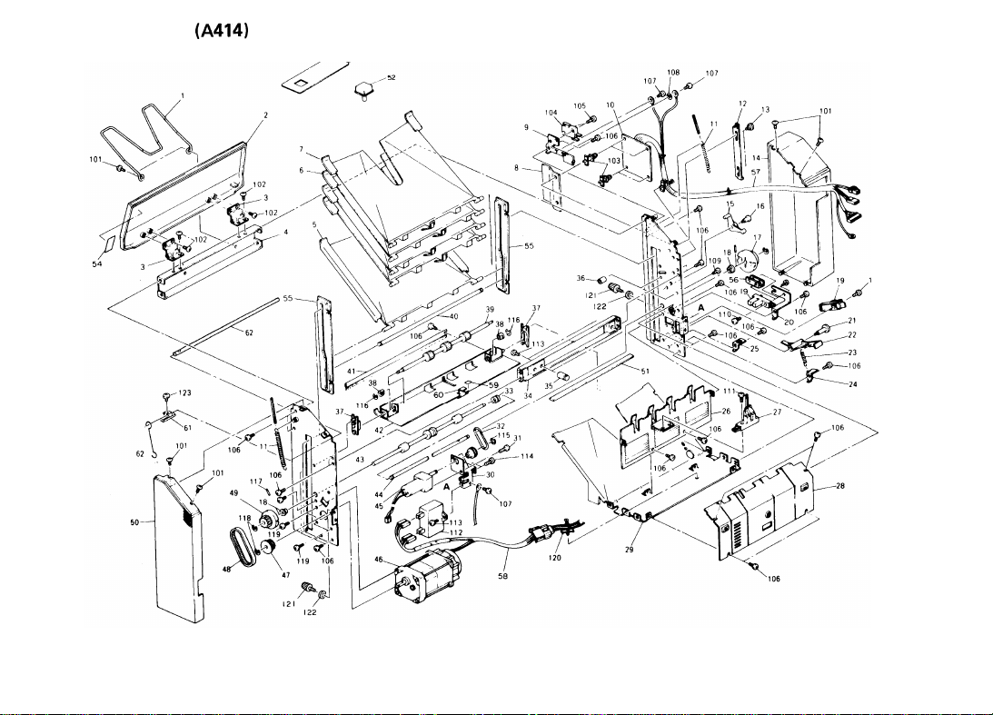
(A414)
Page 2

1. Mini Sorter (A414) . . . . . . . . . . . . . . . . . . . . . . 2
2. Bin Motor Board (A414) . . . . . . . . . . . . . . . . . 4
3. Sorter Harness (A414) . . . . . . . . . . . . . . . . . . . 6
Parts Index . . . . . . . . . . . . . . . . . . . . . . . . . . . . . . . . 9
Page 3
1. MINI SORTER
(A414)
Jan. 31, ’89
,-’---. /53
10
>
Page 4

1. MINI SORTER (A414)
- . - . . . . .,
Index
Part No.
No.
I
*
A411
*
A414
*
A414
5917 1641
1
2
A414
3
6803 6911
4
A414
5
A414
6
A414
7
A414
8
6803 6411
9
6803 4431
10
6803 5500
11
6803 3311
12
6803 2271
13
5403 2075
14
A414
15
6803 2272
16
6803 2273
●
17
A423
18
5053 0447
19
5205 5250
6803 3426
20
6803 3412
21
6803 3411
22
6803 3413
23
24
6803 3414
25
6803 4441
6803 2311
26
6803 5430
27
6803 2111
28
29
A414
30
6803 4411
31
6803 4216
32
6803 4316
I
6522
Multi-Lingual Decal
8611
Installation Procedure - English
8616
Installation Procedure - 5 Language
Original Holder
6311
Upper Cover
Hinge - Upper Cover
1141
Upper Stay
3211
Sorter Bin - Bottom
3151
Sorter Bin - Even
3111
Sorter Bin - Odd
Indurating Plate
Bracket - Safety Switch
Bin Motor Board
Transfer Wheel Shaft
Lever - Upper Guide Plate
Stepped Screw
6211
Rear Cover
Arm - Upper Guide Plate
Stepped Screw -
3327
Transfer Wheel
Bushing - M6
L.E.D. Sensor Type S
Bracket - Half Turn Sensor
Stepped Screw Lever - Home Position Sensor
Lever Spring
Lever Stopper
Cover Bracket
Cover – Electrical Section
Paper Exit Sensor
Lower Guide Plate
1131
Base Plate
Cover Bracket
Pulley
O-Ring
Description
M4
M4
Q’ty Per
Assembly
I
Jan. 31, ’89
Index
Part No.
No.
6803 2415
1
1
1
1
1
1
1
1
10
10
1
1
1
2
1
2
1
1
1
1
2
2
1
1
1
1
1
1
1
1
1
1
1
1
1
33
34
35
36
37
38
39
40
41
42
43
44
45
46
46
47
48
49
50
51
52
53
54
55
56
57
58
59
60
61
62
63
6803 1151
6803 1161
6803 2261
6803 2221
6803 2231
6803 2241
6803 3316
AA12 1001
6803 2151
6803 2410
6803 333!
6803 5410
6803 5400
6803 5420
6803 4211
6803 4311
6803 3321
A414
6111
6769 1128
5918 4020
6803 7512
A414
6512
6803 1115
6803 3427
6803 5610
6803 5600
A414
6521
A411
2531
A423 3511
A423 3513
A423 3517
Drive Pulley
Mounting Stay
Upper Mounting Stud
Dumper - Upper Guide Plate
Guide - Upper Guide Plate
Bushing -
Upper Exit Roller
Lift Bar
Antistatic Brush
Upper Guide Plate
Lower Exit Roller
Transfer Wheel Shaft
Paper Exit Motor
Bin Motor - AC
Bin Motor Pulley - 18T
Timing Belt - 94XL
Front Transfer Wheel
Front Cover
Mounting Stay Magnet
Option Key Top
Sorter Key Cover - English
Jam Removal Decal
Slot Liner
Holder - Half Turn Sensor
Interface Harness
Main Harness
Decal - Guide Plate
Knob Cap
Bin Shaft Positioner
MB 1
Bin Support Shaft
MB 1
Bin Support Wire
MB I
Description
4x6x5mm
14/17W
220V/240V
Q’ty Per
Assembly
1
1
2
1
2
2
1
1
1
1
1
1
1
1
1
1
1
1
1
1
1
1
1
2
1
1
1
1
1
2
1
2
Index
No.
101
102
103
104
105
106
107
108
109
110
111
112
112
113
114
115
116
117
118
119
120
121
122
123
Part No.
0344
O080D
0314 O060W
1105 0162
1204 1318
1313
0140W
0434
O080W
1314
O080M
0704
0040C
0314
Oloow
0314
0120W
0313
O120W
1606 0755
1606 1380
0314
O080W
0965
3010W
0720
O040E
0720 O030E
0632
0140G
0720 O060E
0315
0080W
1105 0196
0803 0019
0807 3090
0313
O060W
Description
Philips Truss Head Screw - M4x8
Philips Pan Head Screw - M4x6
Locking Support
Microswitch
Philips Pan Head Screw Tapping Screw - M4x8
Philips Pan Head Screw - M4x8
Toothed Washer Tapping Screw - M4x1O
Philips Pan Head Screw Philips Pan Head Screw Capacitor Capacitor Philips Pan Head Screw - M4x8
Tapping Screw With Flat Washer - M3x1O
Retaining Ring Retaining Ring Parallel Pin
Retaining Ring Philips Pan Head Screw - M5x8
Harness Clamp
Thumb Screw
Spacer Philips Pan Head Screw - M3x6
10pF
10IJF
L.2x12x2.9mm
M4
220V
(220/240V)
M4
M3
M6
M3x14
M4x12
M3x12
(115V)
Q’ty Per
Assembly
Parts No.
Description
Page and
Index No.
3
Page 5

2. BIN MOTOR BOARD
(A414)
Jan. 31, ’89
CONNECTOR
CN102
I
CN103
CN104
DIODE SSR
SYMBOL INDEX
NO.
D101
102
I
R
104
103
D102
4
I
SYMBOL INDEX
NO. NO. NO.
SSR101
106
106
SSR102
:
105
105
Page 6

2. BIN MOTOR BOARD (A414)
. ..., . . . .
Index
Part No. Description
No.
* 6803 5500 Bin Motor Board
Q’ty Per
Assembly
1
Index
No.
101
102
103
104
105
106
Part No.
1102 0995
1102
1194
[103
1695
[103
1748
1208 1024
1401
0832
Description
onnector – 2P
in Connector - 3P
onnector – 15P
onnector -
olid State Relay
Iiode -
12P
DSAIAI
-
240, 2A
Jan. 31, ’89
Q’ty Per
Assembly
5
Page 7

3. SORTER HARNESS (A414)
Jan. 31, ’89
\\
10
11
/
109
120
115
id’-”
‘
116
\7
104
113
Page 8

3. SORTER HARNESS
—-.
. . .
Index
Part No. Description
No.
1
6803 5600 Main Harness
6803 5610 Interface Harness
2
(A414)
Q’ty Per
Assembly
1
1
Jan. 31, ’89
Per
Index
Part No.
,
101
102
103
104
105
106
107
108
109
110
111
112
113
114
115
116
117
118
119
120
121
122
No.
100
100 1042
.100 1169
1100 1238
1100 1239
[100
1100 1264
1100 1327
1100 1328
1102 0512
1102 0983
1102 1408
1102 1508
1102 1524
1102 1620
1102 1911
1102
1102 1923
1102 1934
1102 1952
1102 1964
1102 1966
0051
1249
1919
JIid Strand
)cket - Mate-N-Lock
~stening Receptacle
In
In
~ceptacle Terminal
arminal
intact
antact
onnector
rmnector - 2P
eceptacle Housing
onnector - 3P
onnector
eceptacle
onnector
onnector
onnector
onnector - 12P
onnector - 2P
onnector - 2P
onnector - 4P
Description
- Mate-N-Lock
- Mate–N-Lock
- 3P
- 2P
Housing - 3P
- 3P
- 11P
- 15P
Q’ty
Assembly
7
 Loading...