

Page 1
FT4480
RICOH COMPANY, LTD.
FIELD SERVICE MANUAL
Page 2

INSTALLATION
1.
15 MARCH 1987
TABLE OF CONTENTS
1.
ENVIRONMENT
2.
MACHINE LEVEL
3.
MINIMUM SPACE REQUIREMENT
POWER REQUIREMENT
4.
5.
COPIER INSTALLATION
6.
COLOR DEVELOPMENT UNIT INSTALLATION
7.
KEY COUNTER HOLDER INSTALLATION
8.
A3/11’’x17” COUNTER INSTALLATION
9.
CASSETTE MODIFICATION
10.
MODIFYING MAIN TRANSFER VOLTAGE
11.
PREPARATION FOR TRANSPORTING THE COPIER
2.
SERVICE TABLE
PM TABLE
SERVICE TABLES
SERVICE REMARKS
SPECIAL TOOLS AND LUBRICATIONS
REPLACEMENT AND ADJUSTMENT
3.
1. OPTICS
2. DEVELOPMENT AND TONER SUPPLY
3. CLEANING
4. QUENCHING
5. PAPER FEED
6. FUSING
7. TRANSPORT
8. CORONA
9. OTHERS
10. COPY IMAGE
1- 1
1- 2
1- 2
1- 3
1- 4
1-12
1-15
1-16
1-17
1-18
1-19
2- 1
2- 3
2-14
2-20
3- 1
3-16
3-25
3-33
3-34
3-54
3-64
3-67
3-77
3-80
4.
ELECTRICAL DATA
SCHEMATICS
TIMING CHARTS
DOCUMENT FEEDER
5.
1. UNPACKING AND INSTALLATION
2. REPLACEMENT AND ADJUSTMENT
4- 1
4- 2
5- 1
5- 9
Page 3

15 MARCH 1987
6. SORTER
1. UNPACKING AND INSTALLATION
2. REPLACEMENT AND ADJUSTMENT
7. LARGE CAPACITY TRAY
1. UNPACKING AND ADJUSTMENT
2. REPLACEMENT AND ADJUSTMENT
8. EDITOR BOARD
1. UNPACKING AND INSTALLATION
9. TROUBLESHOOTING
1. COPY QUALITY
2. SERVICE CALL CONDITIONS
3. DEFECTIVE SENSOR TABLE
6- 1
6- 5
7- 1
7- 7
8- 1
9- 1
9-19
9-30
Page 4

SECTION 1
INSTALLATION
Page 5

CONTENTS
1.
ENVIRONMENT
MACHINE LEVEL
2.
MINIMUM SPACE REQUIREMENT
3.
POWER REQUIREMENT
4.
5.
COPIER INSTALLATION
ACCESSORY CHECK
INSTALLATION PROCEDURE
6.
COLOR DEVELOPMENT UNIT INSTALLATION
ACCESSORY CHECK
INSTALLATION PROCEDURE
7.
KEY COUNTER HOLDER INSTALLATION
A3/11”X17” COUNTER INSTALLATION
8.
CASSETTE MODIFICATION
9.
MODIFYING MAIN TRANSFORMER VOLTAGE
10.
(220V TO 240V)
15 MARCH 1987
1- 1
1- 2
1- 2
1- 3
1- 4
1- 5
1-12
1-13
1-15
1-16
1-17
1-18
11.
PREPARATION FOR TRANSPORTING THE COPIER
SHORT HAUL TRANSPORTATION
LONG HAUL TRANSPORTATION BY VEHICLE
1-19
1-20
Page 6

1. ENVIRONMENT
15 MARCH 1987
1.
Temperature Range:
Humidity Range:
2.
Ambient Illumination:
3.
10°C to 30°C (50°F to 86°F)
15% to 90% RH
Less than 1,500 Iux (Do not expose to direct
sunlight.)
Ventilation:
4.
Ambient Dust:
5.
Room Size:
6.
If the installation place is air-conditioned or heated, place the
7.
Room air should turn over at least 3 times/hour.
Less than 0.15 mg/m
More than 10 m
3
(4 x 10¯³ oz/yd³)
3
(13.4 yd3)
machine:
a.
Where it will not be subjected to sudden temperature changes.
b. Where it will not be directly exposed to cool air from an air
conditioner in the summer.
Where it will not be directly exposed to reflected heat from a
c.
space heater in winter.
8.
Avoid placing the copier in an area filled with corrosive gas.
9.
Avoid any area higher than 2,000 meters (6,500 feet) above sea
level.
Place the copier on a strong and level base.
10.
Avoid any area where the copier may be subjected to frequent
11.
strong vibration.
1-1
Page 7

15 MARCH 1987
2. MACHINE LEVEL
Front to back: Within 5 mm (0.2”) of level
1.
Right to left: Within 5 mm (0.2”) of level
2.
Place the machine on a table and screw the leveling foots [A] up or
down to level the machine.
Use a leveling gauge if necessary.
3. MINIMUM SPACE REQUIREMENT
1.
Front: 70 cm (27.6”)
Back: 10 cm (3.9”)
2.
Right: 80 cm (31.5”)
3.
4.
Left :
10 cm (3.9”)
1-2
Page 8

4. POWER REQUIREMENT
1. Input voltage level
110V/60Hz : More than 15A
115V/60Hz : More than 15A
220V/50Hz : More than 8A
220V/60Hz : More than 8A
240V/50Hz : More than 8A
2. Permissible voltage fluctuation: ± 10%
15 MARCH 1987
3. Permissible extension cord: At least 300V, 30A capacity and less
4. Do not set anything on the power cord.
NOTE: -
Be sure to ground the machine.
gas pipe.)
- Make sure the plug is firmly inserted in the outlet.
- Avoid multi-wiring.
than 5 meters (16.4 ft) long.
(Do not connect the grounding wire to a
1-3
Page 9

15 MARCH 1987
5. COPIER INSTALLATION
- ACCESSORY CHECK -
Check the quantity and condition of the accessories in the box
according to the following list.
DESCRIPTION
1. Installation Procedure
(115V - English only. 220V/240V - five languages)
2. New Equipment Condition Report
3. Envelope
4. Cassette America, Europe, Middle East, Philippines
The Rest of Asia,
5. Cassette - Small
America, Europe, Middle East, Philippines, Taiwan
The Rest of Asia
6. Receiving tray
7. Original holder
8. Operating instructions
(115V - English only. 220V/240V - five languages)
9. Operating instruction cards
(115V - English only. 220V/240V - five languages)
10. Multilingual decals (220/240V only)
11. Sort/Stack key top
(attached on the right inner cover)
12. Sort/Stack key cover
(attached on the right inner cover)
13. Editing Sheet
NOTE: Save the Sorter/Stack key top and cover for Sorter installation.
- NECR (115V only)
Large
Q’TY
1
1
1
1
2
2
1
1
1
1
1
1
1
1
1
1-4
Page 10
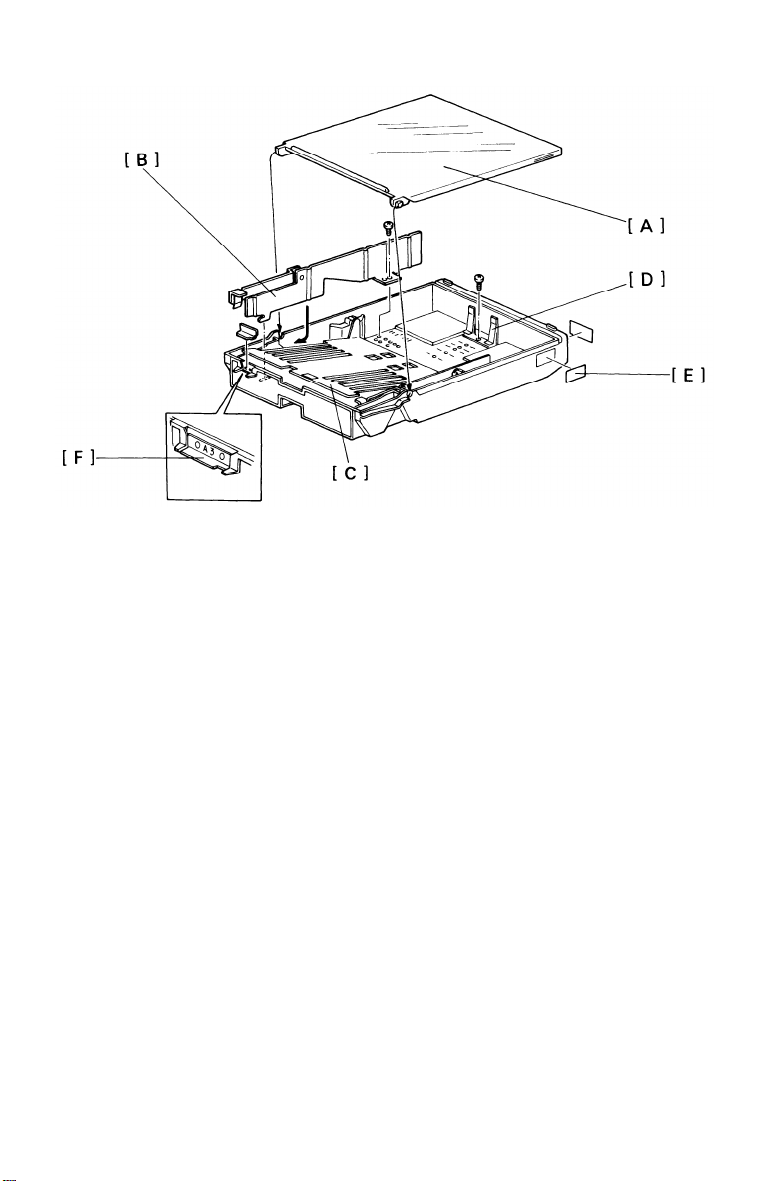
- INSTALLATION PROCEDURE -
15 MARCH 1987
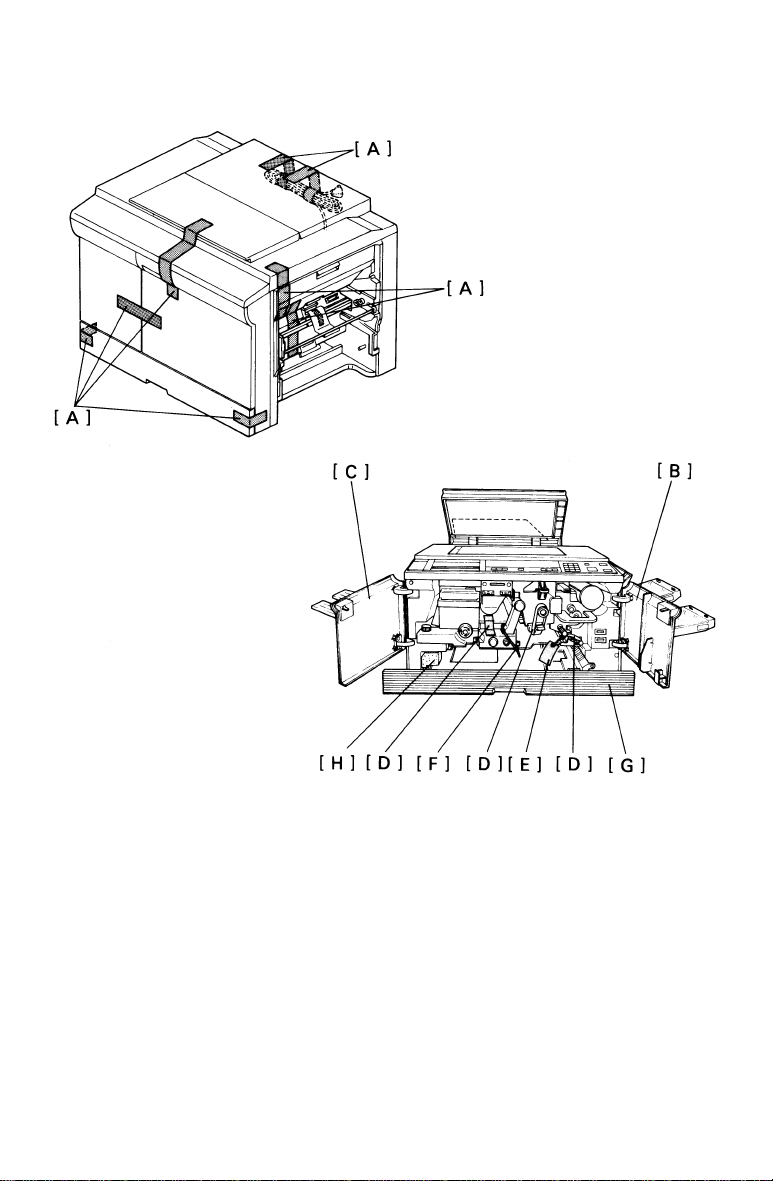
1.
Remove the shipping tapes [A] from the copier as shown.
Open the copier right [B] and left front door [C], remove the shipping
2.
tape [D] and the wedge [E] between the registration rollers, and cut
the cable tie [F] securing the toner collection bottle as shown.
Pull out the cassette tray [G].
3.
Remove the foam rubber [H].
4.
1-5
Page 11
15 MARCH 1987
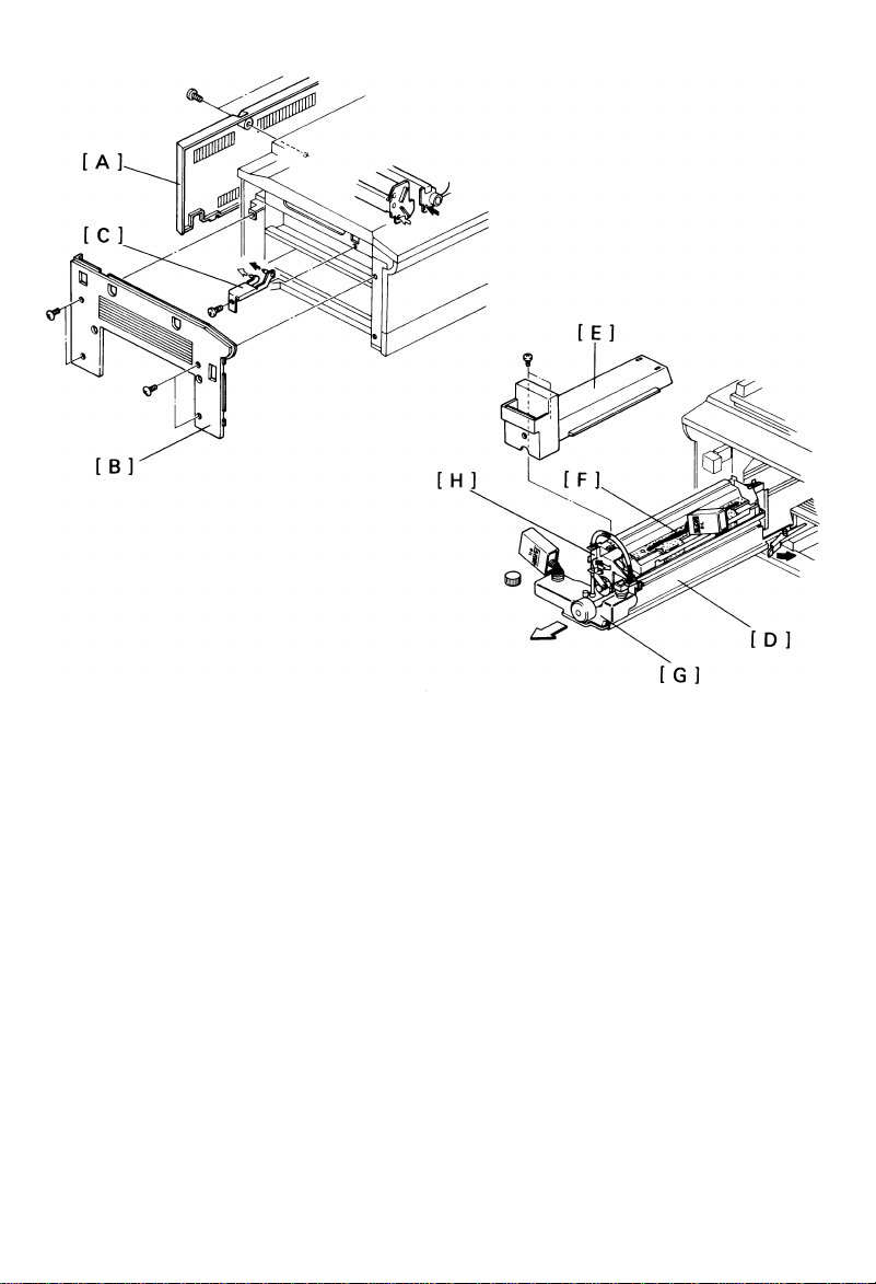
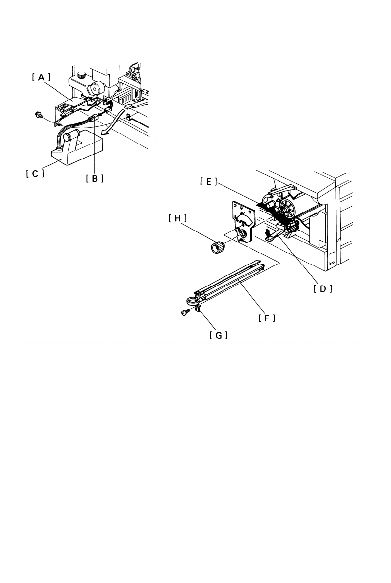
5.
Remove the
6.
Remove the
7.
Remove the
rear cover [A] (2 screws).
left cover [B] (4 screws).
scanner lock plate [C] (1 screw).
NOTE: Save the scanner lock plate for future use.
8.
Reinstall the left cover and rear cover.
9.
Pull out the fusing unit [D] to the lock position and remove the fusing
unit cover [E] (2 screws).
Prime the oil supply pad [F] with silicone oil.
10.
Fill the oil tank [G] with silicone oil.
11.
Manually operate the oil pump lever [H] and confirm the proper
12.
operation and condition of the silicone oil supply system.
Reassemble the fusing unit and return it to its original position.
13.
1-6
Page 12
15 MARCH 1987
14.
Raise the development lock lever [A] and pull out the development
unit [B] and the PTL board [C]. Place the unit on a clean sheet of
paper.
15.
Remove the seal [D] from the toner tank.
Separate the toner tank [E] from the development unit [F] (2 screws).
16.
Pour one bottle of developer [G] into the development unit while
17.
turning the knob [H] counterclockwise to distribute the developer.
Remount the toner tank on the development unit.
18.
1-7
Page 13
15 MARCH 1987
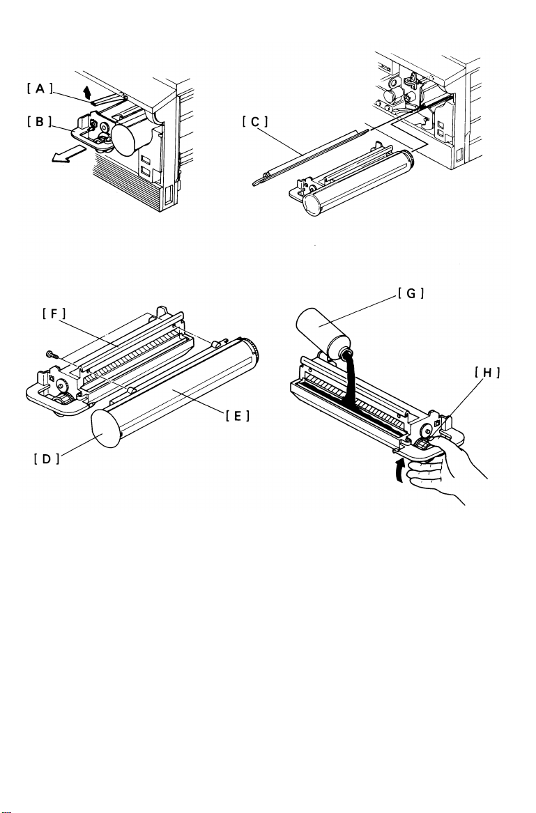
19. Swing the toner collection bottle cover [A] to the left (1 screw) and
unplug the toner overflow sensor connector [B].
20. Remove the toner collection bottle [C].
21. Lower the T/S corona unit [D].
22. Place a sheet of paper [E] over the T/S corona unit.
23. Remove the charge corona unit [F] together with the wire cleaner [G]
(1 screw).
24. Remove the drum stay [I] (1 knob and 1 screw).
NOTE: The drum stay knob [H] is reverse threaded.
1-8
Page 14
15 MARCH 1987
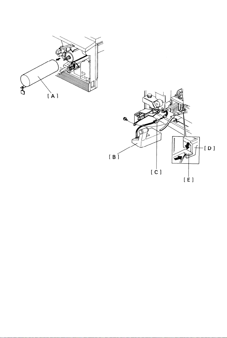
25.
Pull out the drum protective sleeve [A].
NOTE:
26.
Make sure that the wire cleaner is properly positioned, then reinstall
Save the drum protective sleeve for future use when servicing the copier.
the drum stay and the charge corona unit.
27.
Remove the paper over the T/S corona unit and return the T/S
corona unit to its original position.
28.
Reinstall the toner collection bottle [B] and plug in the toner overflow
sensor connector [C].
29.
Make sure that
underneath the
bottle cover [F]
the hooks of the transport plate [D] are positioned
bottle cover [E], then reinstall the toner collection
(1 screw). Close the cassette tray.
1-9
Page 15
15 MARCH 1987
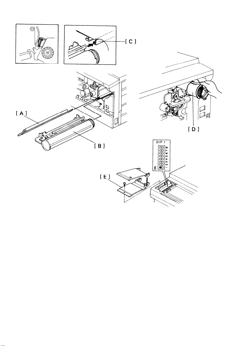
30. Reinstall the PTL board, then reinstall the development unit.
CAUTION: When installing the PTL board [A], be sure that the PTL board is
properly positioned in the rail. When installing the development unit [B],
be sure the development unit rail is properly engaged with the unit
guide rail [C] on the copier.
31. Install
one toner cartridge [D].
NOTE:
Confirm that the toner cartridge gear is properly engaged by attempting to
rotate the cartridge counterclockwise.
When the toner cartridge gear is properly engaged, the toner cartridge will
not rotate freely.
32. Remove the DIP switch cover [E] on the left side of the operation
panel (1 screw) and turn on DIP switch No. 1 - 1.
1-10
Page 16
15 MARCH 1987
Lower the platen cover.
33.
Plug in the machine and turn on the main switch.
34.
After the warm up period is completed, enter 99 copies and
35.
the Start Key for drum conditioning.
After the machine stops, turn off the main switch.
36.
Turn off DIP switch No. 1 -
37.
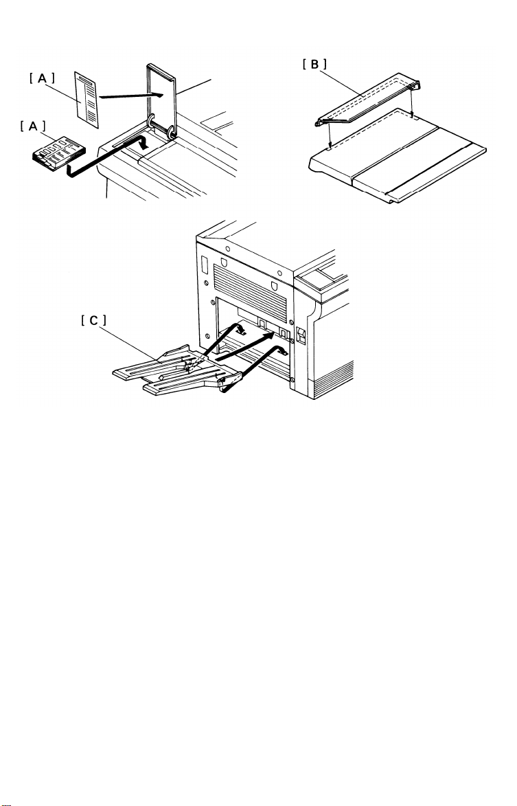
38.
Install the operating instruction cards [A] over the DIP Switch
1 and reinstall the DIP switch cover.
as shown (double-sided tape).
39.
Install the original holder [B] on the platen cover as shown and
the receiving tray [C].
40.
Load paper into the cassette and check machine operation and copy
quality.
41.
Fill out the New Equipment Condition Report.
1-11
press
cover
install
Page 17

15 MARCH 1987
6. COLOR DEVELOPMENT UNIT INSTALLATION
- ACCESSORY CHECK -
Check the quantity and condition of the accessories in the box
according to the following list.
1. Actuator - Red
2. Actuator - Blue
3. Actuator - Green
4. Screw - M3x4
5. Color Decal Sheet
1
1
1
1
1
1-12
Page 18
- INSTALLATION PROCEDURE -
15 MARCH 1987
NOTE: -
The color development unit should be installed after drum conditioning
is finished. (See the copier installation procedure.)
The following procedure should be done when the color developer is
replaced.
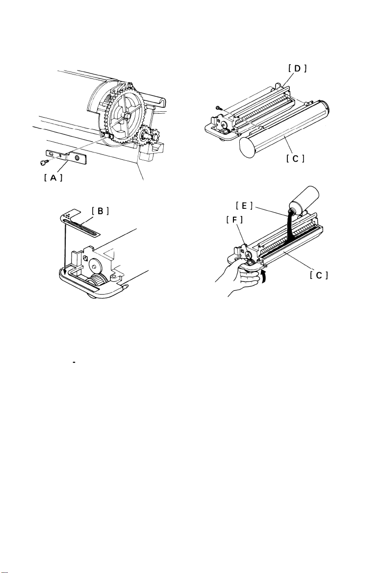
1. Install the color actuator [A] on the color development unit (1 screw).
NOTE: Each actuator has a colored sticker. Install the appreciate actuator.
2. Stick the appreciate decal [B] on the development unit handle.
3. Separate the toner tank [C] from the development unit [D] (2 screws).
4. Pour one bottle of color developer [E] into the development unit while
turning the knob [F] counterclockwise to distribute the developer.
1-13
Page 19
15 MARCH 1987
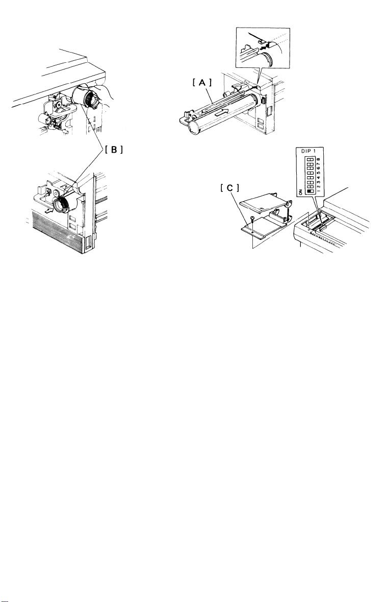
5. Remount the toner tank on the development unit.
CAUTION:
When installing the color development unit, be sure the development
unit rail is properly engaged with the unit guide rail on the copier.
6. Install a color development unit [A].
7. Install the color toner cartridge [B].
8. Remove the DIP SW cover [C] on the
left side of the operation panel
(1 screw) and turn on DIP SW No. 1 - 1.
9. Plug in the machine and turn on the main switch. Confirm that the
Color Toner indicator is displayed on the operation panel.
10. Press the Enter key.
“20” will be displayed on the copy counter.
11. Put five sheets of white paper (A3 or 11”x17”) on the exposure
glass.
12. Lower the platen cover.
13. After the warm up period is completed, press the Start key.
14. After the machine stops, turn off the main switch and the DIP SW
No. 1 - 1.
15. Reinstall the DIP SW cover (1 screw).
1-14
Page 20
7. KEY COUNTER HOLDER INSTALLATION
15 MARCH 1987
NOTE: Three types of counters are recommended for this copier (Ricoh, Hecon, and
1.
2.
3.
4.
5.
6.
7.
8.
9.
10.
11. Reinstall all covers.
Hengstler key counters).
Open the right front door.
Pull out the cassette tray [A].
Remove the
Remove the
Remove the
Remove the
Remove the
Connect the 4p connector of the key counter holder [F] to the key
counter harness through the key counter access hole.
Hold the fixing plate on the inside of the key counter bracket [G] and
insert the key counter holder.
Align the holes in the fixing plate with the mounting holes of key
counter holder and secure the key counter holder.
NOTE: The fixing plate has three sets of holes. Make sure to use the holes that
right inner cover [B] (3 screws).
right front door.
front right side cover [C] (2 screws).
cover plate [D] (2 screws).
shorting plug [E] from the 4p key counter connector.
match the type of counter when installing.
1-15
Page 21
15 MARCH 1987
8. A3/11”X17” COUNTER INSTALLATION
1. Open the right front door.
2. Pull out the cassette tray [A].
3. Remove the right inner cover [B] (3 screws).
4. Remove the A3/11”X17” counter cover plate [C] (2 screws).
5. Push the A3/11”X17” counter [D] into the space provided until it
locks.
6. Connect the 2p connector [E] on the A3/11”X17” connector to the
counter harness [F].
7. Reinstall the right inner cover.
1-16
Page 22
15 MARCH 1987
9. CASSETTE MODIFICATION
Remove the cassette cover [A].
1.
Remove the side fences [B] (1 screw each) and the bottom plate [C].
2.
Reposition the rear fence [D] in the desired paper size position (1
3.
screw).
NOTE: Paper size positions are shown on the inside of the cassette.
Reinstall the bottom plate.
4.
Reinstall the side fences in the desired paper size position.
5.
6.
Attach the proper paper size decals [E] on the cassette at the
positions shown.
Insert the actuator plate [F] in the slot on the front of the cassette
7.
as shown.
NOTE: The actuator plates are enclosed in the cassettes.
Save the other actuator plates for future use.
1-17
Page 23
15 MARCH 1987
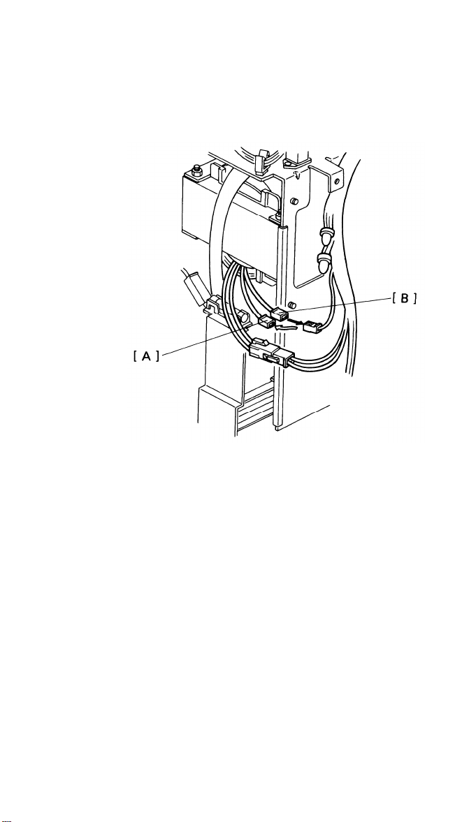
10. MODIFYING MAIN TRANSFORMER VOLTAGE (220V TO 240V)
1. Remove the rear cover (2 screws).
2. Disconnect the 220V connector [A] (White:1P).
3. Connect the 240V connector [B] (Red:1P).
4. Reinstall the rear cover.
1-18
Page 24
15 MARCH 1987
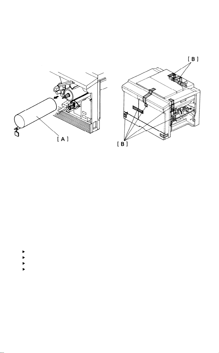
11. PREPARATION FOR TRANSPORTING THE COPIER
- SHORT HAUL TRANSPORTATION -
The copier may be seriously damaged if it is moved without proper preparation. Before moving the copier from its place of installation, be sure
to prepare it for transportation as follows:
1. Insert the drum protective sleeve [A].
2. Re-install the development unit.
3. Re-install the drum stay and charge corona unit.
4. Secure the following items with tape [B]:
Manual feed table
Platen cover or document feeder
Power supply cord (roll up first)
Cassette tray front cover
5. Remove the sorter to prevent damage to the bins.
6. Remove the cassettes.
7. Remove the original table from the document feeder.
8. Remove the LCT if it is installed in the 2nd feed station.
1-19
Page 25
15 MARCH 1987
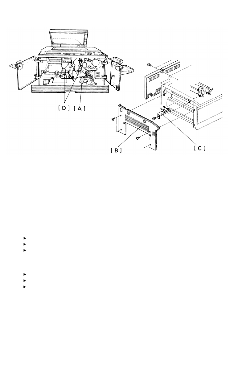
- LONG HAUL TRANSPORTATION BY VEHICLE -
If the machine is to be transported by vehicle, do
the following steps
after you have completed the short haul procedure.
1.
Remove the developer from the development unit.
Place a wedge [A] between the registration rollers.
2.
Remove the left cover [B] and install the scanner lock plate [C].
3.
NOTE: Confirm that the scanner is at the home position.
4.
Secure the following items with tape [D]:
T/S corona release lever to the drum stay knob
Transport plate to the toner collection bottle cover
1st and 2nd feed guide plates
Remove the sorter and secure the following items with tape:
5.
Top cover
Jam clearing tray
Bins--tape the right and left edges of the spacers together.
Secure the LCT covers and power supply cord with tape.
6.
1-20
Page 26

SECTION 2
SERVICE TABLES
Page 27

CONTENTS
15 MARCH 1987
PM TABLE
SERVICE TABLE
1. TEST POINTS
2. VARIABLE RESISTERS
3. DIP SWITCHES
4. SERVICE PROGRAM MODE (SP MODE OPERATION)
5. SERVICE PROGRAM MODE TABLE
SERVICE REMARKS
SPECIAL TOOLS AND LUBRICANTS
2- 1
2- 3
2- 4
2- 5
2- 8
2- 9
2-14
2-20
Page 28

PM TABLE
C: Clean R: Replace L: Lubricate
15 MARCH 1987
ITEM
OPTICS
1. Mirrors, lens, reflectors, toner
shield glass, ADS
sensor
2. Exposure glass
2. Platen cover sheet
4. Scanner guide rod
and plate
5. Guide rod felt
PAPER FEED
6. Paper feed roller
7. Friction pad
8. Paper feed guide
plate
9. Registration sensor
10. Cassette bottom
plate pad
11. Paper feed sensor
AROUND DRUM
12. Corona wires
13. Wire cleaner
14. End blocks and casing
15. Transfer guide plate
16. Pre-Transfer Lamp
17. Quenching Lamp
18. ID sensor
19. Erase lamp unit
EM
60K 120K 180K
240K
C C C C C
C C C C C
C C C C C
L
L
L L
L
L L
C R R
C R R
C C C C
C
C
C
C C
C
C C
C C C C
C
R R
R R R R
C C
C
C
C C
C C C
C C C C C
C C C C C
C C C C C
C C C C
NOTES
Silicone cloth or water
(cotton pad), blower brush
Alcohol or water
Alcohol or water (replace if
necessary)
Launa oil or equivalent
L
Launa oil or equivalent
Water
Water
Blower brush
Alcohol or water
Blower brush
Dry cloth
Dry cloth
Dry cloth
Dry cloth, discharge before
installation.
Dry cloth, discharge before
installation.
Blower brush
Dry cloth
CLEANING UNIT
20. Cleaning blade
21. Cleaning seal
22. Cleaning brush
23. Cleaning unit
24. Pick-off pawls
25. Used toner bottle
R R R R
C C C C
R R
C C C C
C
C C C C
C C C C C
2-1
Dust with setting powder
Replace if necessary
Dust with setting powder
Replace if necessary
Empty of used toner
Page 29

15 MARCH 1987
C: Clean R: Replace
L: Lubricate A: Add I: Inspect
ITEM
DEVELOPMENT UNIT
26. Developer
27. Upper brush seal
28. Side seals
29. Development unit guide
30. Toner supply clutch
FUSING UNIT
31. Hot roller
32. Pressure roller
33. Stripper pawls
34. Oil supply pad
35. Oil blade
36. Fusing entrance and
exit guides
37. Oil sump
OTHERS
38. Main drive chain
39. Transport belt
40. Bushings
DOCUMENT FEEDER
41. Belt
42. Pick-up roller
43. Feed roller
44. Friction roller
60K 120K 180K
EM
R R R R
C C C C
C C C C
C C C C
L L
C R
C R
C C C C
R R
C R
C C C C
C C C C
L L
C C
L
C C C C
C
C C C C
C
C C C C
C
C C C C
C
240K
C R
C R
R R
C R
C C
NOTES
If necessary
Mobil Temp 78
If necessary
Replace if necessary
Prime with silicone oil
Prime with silicone oil
Suitable solvent
Spindle oil
Alcohol or water
L
Spindle oil
Belt cleaner, replace if
necessary
Water, replace if necessary
Water, replace if necessary
Water, replace if necessary
LARGE CAPACITY TRAY
45. Pick-up roller
C R R
2-2
Water
Page 30

SERVICE TABLES
1. Test Points
-
MAIN BOARD -
15 MARCH 1987
NUMBER
TP201
TP202 +5V (Vc)
TP203
TP204 Factory Use
TP205
CN212-1 ADS Voltage
CN209-1 Input voltage of image density sensor
- DF MAIN BOARD NUMBER
TP101
TP102
TP103
TP104
TP105 BeIt drive motor encoder pulse
FUNCTION
GND
+24V (VA)
+12V (Vs)
(Adjust using VR2 on the lamp regulator)
(Adjust using VR201 on the main board)
FUNCTION
GND
+24V (VA)
+12V (Power for motor control IC)
+5V (Vc)
2-3
Page 31

15 MARCH 1987
2. Variable Resisters
- MAIN BOARD NUMBER
VR201 Adjust the image density sensor voltage
- LAMP REGULATOR NUMBER
VR1
VR2
VR3
- DF MAIN BOARD NUMBER
VR101 Registration adjustment (0 ± 2.5 mm)
VR103 Belt drive motor speed adjustment
VR104 Original entrance sensor output
VR105 Original width sensor output
FUNCTION
FUNCTION
Light adjustment
ADS input adjustment
Factory Use
FUNCTION
(2,500 ± 30 rpm)
(IC 116-5 > +8V : With paper)
(IC 116-5 < +4V : Without paper)
(IC 116-7 > +8V : With paper)
(IC 116-7 < +4V : Without paper)
2-4
Page 32

3. Dip Switches
- Main Board DIP 101
15 MARCH 1987
DIP SWITCH
101-1 --- Lead edge registration adjustment
101-2 --- Lead edge registration adjustment
101-3 --- Lead edge registration adjustment
101-4 --- Lead edge registration adjustment
101-5 --- Lead edge blank margin adjustment
101-6 --101-7 --- Lead edge blank margin adjustment
101-8 ---
(Lead edge regist./blank margin adjustment interval = 1.0 mm per step.
See the adjustment procedure.)
DIP 102
DIP SWITCH
102-1
102-2 --102-3 --102-4 ---
(Vertical magnification adjustment interval = 0.2% per step. See the
vertical magnification adjustment procedure.)
DIP 201
NORMAL FUNCTION
Lead edge blank margin adjustment
Lead edge blank margin adjustment
NORMAL
OFF
FUNCTION
Scanner free run
Vertical magnification adjustment
Vertical magnification adjustment
Vertical magnification adjustment
DIP SWITCH
201-1
201-2
201-3
201-4
201-5
201-6
201-7
201-8
NORMAL
OFF
ON
OFF
OFF
ON
OFF
OFF
OFF
FUNCTION
Toner supply mode (ON: fixed, OFF: detect)
Toner supply amount (Note 1)
Toner supply amount (Note 1)
Image density adjustment (Note 2)
Image density adjustment (Note 2)
Increase bias (+30 V; Color)
Increase bias (+90 V)
ID sensor LED ON
2-5
Page 33

15 MARCH 1987
NOTE 1: Dip SW 201-1, 2, 3
201-2 201-3 Detect Mode Fixed Mode
(201-1 OFF) (201-1 ON)
OFF OFF
ON OFF
OFF ON
ON ON
15%
30%
3.5%
7.0%
45% 10.5%
60%
14.0%
NOTE 2: Dip SW 201-4, 5
201-4 201-5
OFF OFF
ON OFF
OFF ON
ON ON
Image Density
Light (least toner)
Lighter (less toner)
Normal
Dark {more toner)
DIP 202
DIP SWITCH
102-1
102-2
102-3
102-4
NORMAL
OFF
OFF
OFF
OFF
FUNCTION
Sorter instructions
Auto cassette shift disable
Not used
Not used
ID sensor Bias
470V
440V
500V
530V
2-6
Page 34

Operation Panel -
-
DIP 1
15 MARCH 1987
DIP SWITCH
1-1
1-2
1-3
1-4
1-5
1-6
1-7
1-8
NORMAL
OFF
OFF
OFF
OFF
OFF
OFF
OFF
OFF
- DF Main Board DIP 101
101-1 101-2 101-3 101-4
ON
ON
ON ON
OFF OFF OFF
OFF OFF OFF
OFF ON
ON ON ON ON
FNUCTION
Drum conditioning
Free run
Jam detection disable
Auto reset disable
Beeper sound disable
Copy counter count up/down
(ON: down, OFF: up)
Manual image density mode priority
(ON: manual mode, OFF: ADS mode)
SP Mode
FUNCTION
Normal mode
Free run
Belt speed adjustment (VR103)
All indicator on
2-7
Page 35

15 MARCH 1987
4. Service Program Mode (SP Mode) Operation
The service program mode is used to check and change electrical data or
adjustment values by the service engineer.
- DATA CHANGE MODE -
1.
Remove the DIP SW cover and turn on DIP SW1-8 on the operation
panel. (The Service Call indicator will start blinking.)
Enter the desired SP Mode No. using the numeral keys.
2.
(The entered No. is displayed in the copy counter.)
Press the Enter key.
3.
(The SP Mode No. is shifted into the Magnification indicator and the
actual data is displayed in the copy counter.)
If the data is correct, press the Enter key.
4.
5.
Enter the desired data using numeral keys.
(The data entered is displayed in the copy counter.)
Press the Enter key to memorize the new data.
6.
(The copy counter indicates “1”,
the Start key turns green.)
Turn off the DIP SW1-8.
7.
(The Service Call indicator goes off.)
the Ready indicator turns on and
- DATA CHECK MODE -
Perform the steps 1 and 2 of the data change mode.
1.
Press the Enter key.
2.
(The data is displayed in the Magnification indicator.)
Perform the adjustment procedure for the SP Mode No.55 and 56. if
3.
necessary.
Turn off the DIP SW 1-8.
4.
NOTE: -
The SP Mode can be cleared by pressing the Clear mode key or
turning off the main switch.
2-8
Page 36

5. Service Program Mode Table
15 MARCH 1987
Mode No.
5 Exposure Lamp
OFF
9 ADS
11 All Indicators
ON
15 Auto Reset
Time
20 Feed Station
Priority (LCT)
21 APS Priority
22 Feed Station Pri-
ority (1st, 2nd,
and 3rd cassette)
Function
Exposure lamp ON/OFF
Data
0: ON
1: OFF
ADS voltage adjust-
-
ment
Turns on allindica-
tors on the operation
panel.
Selects auto reset
of 1 or 3 minutes.
Selects feed station
priority.
Selects APS or manual. 0: APS
selects feed station 0: 1st
priority.
0: 1 min.
1: 3 min.
0: LCT
1: SP 22
1: Manual
1: 2nd
2: 3rd
Factory
Setting
0
-
0
0
0
0
Remarks
For use with SP
Mode “56”.
Refer to the ADS
adjustment procedure.
Auto Reset time
can be switched
OFF by DIP SW 1-40N.
Refer to the NOTE 1.
If DF is installed.
Refer to the NOTE 1.
23 DF Original
Size
Enables originals of
various sizes to be
fed from the same
stack.
2-9
0: OFF
1: ON
0
ADF Mode only.
Page 37

15 MARCH 1987
Mode No.
28 Auto Sort Mode
29 Fusing Unit
Idle
35 Toner Supply
49 Fusing Tempera-
ture Change
52 Fusing Temper-
ature
55 VSG, VSP
Voltage
56 ADS lnput Refer-
rence Voltage
Function
Selects Sort Mode
automatically in ADF
0: Manual
1: Auto
mode.
Selects fusing unit
idling mode
Changes toner supply
interval.
0: No idling
1: idling
0: Standard
1: Increase
a) ID sensor checks
every 5 copies.
b) Toner end level
changes to 0.65V.
Changes fusing temp.
0: Standard
Displays the fusing
temperature.
Displays VSG, VSP
voltage
Displays ADS voltage
Data
1: Low
2: Higher
3: Highest
-
-
Factory
Setting
0
0
0
0
-
Remarks
Sorter and DF must
be installed.
Copier will idle
for 10 seconds.
Refer to the NOTE 3.
Standard:
Every 10 copies,
0.75V.
178 - 184°
174 - 180°
182 - 188°
186 - 192°
Press the enter
key twice to
Display Vsp.
For use with SP
Mode “9”.
59 Bias Voltage
60 Toner Supply
Recovery
Displays bias voltage
Recover toner volume
if the Vsp is above
0.5V.
a) Press Start key.
b) Toner supply clutch
turns on.
c) Free run starts.
d) Vsp becomes less
than 0.5V.
e) Free run stops.
2-10
Refer to the ADS
adjustment procedure.
Press the Start key
to indicate the voltage.
Use this mode if
the image density
is low. (Black toner
only).
Refer to the NOTE 2
for color toner
Page 38

15 MARCH 1987
Mode No.
70 Color Toner
Supply Amount
73 Color Toner
Copy Count
76 Sorter Bin
Capacity
93 Maximum Copy
Quantity
99 Clear All
Memory
Function
Selects the color
toner supply ratio.
Shows the number
of color copies
made
Set the stack mode
quantity limit.
Limits the maximum
copy quantity that
can be entered.
Clear All counters
and returns all modes
to factory setting.
Data
0: 14%
1: 7%
2: 21%
3: 28%
4: 35%
5: 42%
6: 49%
7: 56%
0: Red
1: Green
2: Blue
0: No Iimit
1: Limit
0: Memory
1: Clear
Factory
Setting
0
0
0
(999)
0
Remarks
Multiply number
by 100. Example:
24 = 2400 sheets
Limit is determined
by paper size.
Refer to the NOTE 4.
The limit quantity
is displayed in the
copy counter.
(Refer to the NOTE 5.)
DIP SW 1-1 must be
ON.
2-11
Page 39

15 MARCH 1987
NOTE 1: SP Mode No.20 and 22.
Feed Station Priority
SP Mode 20
SP Mode 22
First Priority
Second Priority
Third Priority
LCT Not Installed
x x x
0 1 2 x 0 1 2
2nd
3rd
1st
3rd
1st
2nd
1st
2nd
3rd
LCT Installed
0 1 1 1
2nd
1st
2nd
3rd
2nd
3rd
1st
3rd
1st
3rd
1st
2nd
NOTE 2: SP Mode No.60.
For the color toner supply recovery, the following procedure is required:
1. Turn off the main switch and turn on DIP switch 1-2.
2. Turn on the main switch, then press the start key.
3. While pressing the enter key and the “0” key, the toner supply clutch
turns on.
4. Press the Clear/Stop key and turn off the main switch, then turn off
DIP switch 1 - 2.
NOTE 3: SP Mode No.29
The idling mode may be necessary if the copier has been instaIled in
an environment with low temperature place.
The idling mode will warm up the fusing rollers enough to ensure the
fusing ability at initial copy run.
Idling Mode: The copier will idle for 10 seconds only when the main
switch turned on and the Start key turned on.
2-12
Page 40

NOTE 4: SP Mode No.76
15 MARCH 1987
Paper Size
A3/DLT
A4/LT
A5/HLT
Limit Capacity
10 sheets
30 sheets
30 sheets
NOTE 5: SP Mode No.93
To change the limit quantity, perform the following:
1. Turn the DIP SW 1-8.
2. Enter “93” using the numeral keys.
3. Press the Enter key.
4. Enter a desired number using numeral keys.
5. Press the Enter key.
2-13
Page 41

15 MARCH 1987
SERVICE REMARKS
- Handling the Drum -
Never touch the drum surface with bare hands.
1.
Store the drum in a cool dry place.
2.
Always wear gloves when cleaning the drum.
3.
Prime the drum with setting powder only when installing new drum.
4.
Never expose the drum to light for a long time.
5.
Drum conditioning is necessary when a new drum is installed. In addi-
6.
tion, it is useful at the following times:
• When image density is reduced due to over-exposure of the drum.
• After cleaning the drum.
• When the drum is lightly scratched.
Always keep the drum in the protective sleeve when inserting or pul-
7.
ling the drum out of the copier.
Before inserting or pulling out the drum, the cleaning unit should be
8.
pulled slightly out to avoid drum damage by the pick-off pawls.
Return used drums to the distributor according to standard procedure.
9.
2-14
Page 42

15 MARCH 1987
- Charge Corona -
Clean the corona wires with a dry cloth or by sliding the corona unit
1.
in and out. Do not use emery paper or any solvent for wire cleaning.
Do not touch the corona wires with oily hands. Oil stains may cause
2.
white bands on copies.
Make sure that the corona wires are correctly positioned between the
3.
cleaner pads and there are no threads on the casing.
When adjusting the drum current, always make sure that the axis of
4.
drum shoe is aligned with the corona wire.
The corona wire height should be adjusted only when:
5.
a) The front end block is replaced.
b) The drum charge current is uneven.
- Optics -
Do not adjust the following parts:
1.
a. Scanner Guide Plate
b. Fourth Mirror Angle Adjusting Screw
c. Lens Home Position Sensor
d. Lens unit rails
The lens home position sensor does not have a convenient adjusting
2.
procedure. When replacing the sensor, mark the position of the sensor
bracket before removing it, and adjust the fine position of the sensor
by checking the copy image (horizontal magnification and focus).
Do not bend or damage the lens support plate or the mylar strip.
3.
Launa oil or an equivalent oil should be used
4.
to lubricate or clean the
following:
• Scanner Guide Rod (cleaning)
• Scanner Guide Rod Pads (Lubrication)
• Scanner Guide Plate (Lubrication/Cleaning)
CAUTION: Do not use any other kind of oil.
Clean the exposure glass with glass cleaner and a dry cloth to
5.
reduce static electricity on the glass.
Clean the mirrors with water or silicone cloth only.
6.
2-15
Page 43

15 MARCH 1987
7.
Do not touch the following parts with bare hands:
• Reflectors
• Exposure Lamp
• Mirrors and Lens
8.
Do not bend the Auto ID fiber optics cable sharply.
9.
When adjusting the light intensity, make ten copies before proceeding
to check copy image if the main switch has just been turned on. This
is to eliminate the effect of rest time compensation.
After adjusting the light intensity, check and adjust the Auto ID
10.
sensor.
- Development -
1.
Be careful not to nick or scratch the development roller sleeve.
Place a sheet of paper under the development unit when it is
2.
the copier.
Be careful not to bend the bias terminal.
3.
Clean the drive gears and end magnets after removing used
4.
developer.
Clean the development unit guide plate before reinstalling the unit.
5.
- Toner Supply -
1.
The image density sensor and the pre-transfer lamp unit should be
cleaned with a blower brush.
Do not touch the sensor pattern with bare hands.
2.
Image density sensor adjustment is required when:
3.
• The ID sensor/PTL board is replaced.
• The main board is replaced.
• The drum has been replaced and Vsg is out of specification.
• Problems with toner supply have occurred and ID sensor check
shows Vsg to be out of specification.
Grease the toner supply clutch with Mobil Temp 78 periodically to
4.
avoid noise and faulty operation.
out of
2-16
Page 44

15 MARCH 1987
- Transfer and Separation -
1. The corona wires should be cleaned with a dry cloth.
2. While the drum stay is out and the drum is installed on the drum
guide, do not lift up the corona unit. (The corona casing will knock
against the drum.)
- Cleaning -
1.
When servicing, be careful not to damage the edge of the cleaning
blade.
Do not touch the cleaning brush with your bare hands.
2.
Before pulling out the cleaning unit, place a sheet of paper under it to
3.
catch falling toner.
Be careful not to damage the drum with the pick-off pawls when
4.
pulling out or inserting the cleaning unit.
When installing the toner collection bottle cover, be sure that the
5.
hooks of the transport plate are positioned underneath the bottle
cover.
After replacing the cleaning solenoid, adjust the position of the
6.
cleaning solenoid.
- Fusing -
1.
When removing the
the silicone oil does
After replacing the
2.
fusing unit, keep it in an up-right position so that
not spill.
oil blade and oil supply pad, prime them with
silicone oil.
Be careful not to damage the edge of the hot roller strippers or their
3.
tension springs.
Do not touch the fusing lamp with bare hands.
4.
Be sure that the fusing lamp is not in contact with the inner surface
5.
of the hot roller.
Be sure that the oil end sensor contacts the bottom of the oil tank.
6.
7.
When
the paper creasing occur,
guide
plate or fusing pressure.
adjust the position of the entrance
2-17
Page 45

15 MARCH 1987
- Paper Feed -
1.
When replacing the friction pad, make sure that the friction pad is
below the surface of the front lip of the pad holder.
When reinstalling the support bracket after cleaning the registration
2.
sensor, make sure that the bracket is properly engaged with the
groove of the registration clutch stopper.
When replacing the friction pad, adjust the gap between the feed
3.
roller and the friction pad.
4.
Do not touch the feed roller and the friction pad with oily hand.
- Document Feeder -
1.
Do not bend the DF interface harness sharply to avoid damaging
fiber optics cables.
When servicing the document feeder, make sure that the main switch
2.
of the copier is off.
When installing or reinstalling the document feeder, make sure that
3.
the document feed is in the open position.
- Sorter -
1. The sorter has two types of bins; one type is
bins and the others used for even numbers.
used for odd numbered
Be careful not to mix
them up.
2. If bin operation is not smooth, lubricate the
slot liners and transfer
wheels using grease 501 or equivalent.
- Large Capacity Tray -
1.
Unplug the power supply cord of the LCT before servicing it.
Before placing the large capacity tray in the cassette holders, make
2.
sure that the paper position feeler is set properly.
the
2-18
Page 46

- Others -
15 MARCH 1987
1. When the main board is removed from the PCB plate, do not put it on
a conductive surface.
(This is to avoid discharging the battery for
the user program memory.)
2. When installing a new main board, remove the RAM from the old main
board. Reinstall the old RAM on the new main board, if the old RAM is
not faulty.
3. When installing the PTL board, be sure that the drum stay has been
already installed, if the drum stay is not installed the drum may be
damaged by the PTL board.
4. When replacing a sensor, do not overtighten the screw.
If the screw is overtightened, the sensor may be damage.
5. When taking out drum, be sure that the PTL board has already been
removed, if the PTL board is not removed the drum may be damaged by
the PTL board.
2-19
Page 47

15 MARCH 1987
SPECIAL TOOLS AND LUBRICANTS
Part Number
52159500
52059601
52059101
52059111
52069600
52039501
54429101
54429106
54479104
54209504
54209505
54209507
54209550
54479078
54209516
54209502
54429103
Description
Docotor Gap Gauge
Switching Board
Gap Gauge - 0.1 mm
Omega Clamp
Sensor Checker
Grease (Shinetsu Silicone G-501)
Setting Powder
Drum Shoe
Shoe Adapter
Digital Thermometer
Digital Thermometer Probe
Digital Multimeter
Silicone Oil
Heat Resistant Grease (MT-78)
Test Chart OS-A3 (10pcs/set)
Test Chart OS-A3 (100pcs/set)
Launa Oil
Q’ty
1
1
1
1
1
1
1
1
1
1
1
1
1
1
2-20
Page 48

SECTION 3
REPLACEMENT AND
ADJUSTMENT
Page 49

1. OPTICS
EXPOSURE GLASS REMOVAL
2ND MIRROR REMOVAL
EXPOSURE LAMP REPLACEMENT
AUTO ID FIBER CABLE REPLACEMENT
SCANNER DRIVE WIRE REPLACEMENT
LENS DRIVE MOTOR REPLACEMENT
2ND SCANNER DRIVE MOTOR REPLACEMENT
SCANNER DRIVE MOTOR REPLACEMENT
LENS HOME POSITION SENSOR REPLACEMENT
2ND SCANNER HOME POSITION SENSOR REPLACEMENT
EXPOSURE LAMP POSITION ADJUSTMENT
15 MARCH 1987
CONTENTS
3- 1
3- 2
3- 4
3- 5
3- 6
3- 9
3-10
3-11
3-12
3-13
3-14
2. DEVELOPMENT AND TONER SUPPLY
DEVELOPER REPLACEMENT
lMAGE DENSITY SENSOR/PTLR REMOVAL
COLOR TONER END SENSOR REPLACEMENT
COLOR TONER SENSOR REPLACEMENT
TONER SUPPLY CLUTCH LUBRICATION
lMAGE DENSITY SENSOR CHECK AND ADJUSTMENT
DOCTOR GAP ADJUSTMENT
3. CLEANING
CLEANING UNIT REMOVAL
CLEANING BLADE REPLACEMENT
CLEANING BRUSH REPLACEMENT
BLADE SCRAPER REPLACEMENT
TONER COLLECTION COIL REPLACEMENT
PICK-OFF PAWL REPLACEMENT
CLEANING PRESSURE ADJUSTMENT
4. QUENCHING
QUENCHING LAMP REPLACEMENT
5. PAPER FEED
MANUAL FEED TABLE REMOVAL
FEED ROLLERS AND FRICTION PAD REPLACEMENT
REGISTRATION SENSOR REPLACEMENT
MANUAL FEED SENSOR REPLACEMENT
PAPER END SENSOR REPLACEMENT
PAPER SIZE SENSOR REPLACEMENT
CASSETTE TRAY REMOVAL
PAPER END SENSOR REPLACEMENT
(CASSETTE TRAY)
CASSETTE TRAY SENSOR REPLACEMENT
(CASSETTE TRAY)
3-16
3-17
3-18
3-19
3-20
3-21
3-24
3-25
3-26
3-27
3-28
3-29
3-30
3-32
3-33
3-34
3-35
3-36
3-37
3-38
3-39
3-40
3-41
3-42
Page 50

15 MARCH 1987
PAPER SIZE SENSOR REPLACEMENT
(CASSETTE TRAY)
PAPER SIZE SENSOR HARNESS REMOVAL
(CASSETTE TRAY)
FEED ROLLER REPLACEMENT
(CASSETTE TRAY)
FRICTION PAD REPLACEMENT
(CASSETTE TRAY)
LIFT UNIT REMOVAL
LIFT MOTOR REPLACEMENT
REGISTRATION CLUTCH ADJUSTMENT
FEED ROLLER/FRICTION PAD GAP ADJUSTMENT
(1ST AND 2ND FEED STATION)
FEED ROLLER/FRICTION PAD GAP ADJUSTMENT
(CASSETTE TRAY)
FRICTION PAD HOLDER POSITION ADJUSTMENT
(CASSETTE TRAY)
HORIZONTAL REGISTRATION ADJUSTMENT
(CASSETTE TRAY)
6. FUSING
FUSING UNIT REMOVAL
OIL BLADE REPLACEMENT
HOT ROLLER REPLACEMENT
PRESSURE ROLLER REPLACEMENT
HOT ROLLER STRIPPER REPLACEMENT
THERMISTOR REPLACEMENT
THERMOFUSE REPLACEMENT
FUSING PRESSURE ADJUSTMENT
ENTRANCE GUIDE HIGHT ADJUSTMENT
3-43
3-44
3-45
3-46
3-47
3-48
3-49
3-50
3-51
3-52
3-53
3-54
3-55
3-56
3-58
3-59
3-60
3-61
3-62
3-63
7. TRANSPORT
TRANSPORT UNIT AND TRANSPORT BELT REMOVAL
VACUUM FAN MOTOR REPLACEMENT
8. CORONA
CORONA WIRE REPLACEMENT
I. CHARGE CORONA WIRE
Il. T/S CORONA WIRES
DRUM CURRENT ADJUSTMENT
I. PREPARATION
Il. CHARGE CORONA
Ill. TRANSFER CORONA
IV. SEPARATION CORONA
9. OTHERS
OPERATION PANEL REMOVAL
POWER SUPPLY UNIT REMOVAL
DRUM HEATER REMOVAL
3-64
3-66
3-67
3-69
3-71
3-73
3-75
3-76
3-77
3-78
3-79
Page 51

15 MARCH 1987
10. COPY IMAGE
LIGHT INTENSITY ADJUSTMENT
AUTO ID SENSOR ADJUSTMENT
HORIZONTAL MAGNIFICATION ADJUSTMENT
VERTICAL MAGNIFICATION ADJUSTMENT
LEAD EDGE BLANK MARGIN ADJUSTMENT
3-80
3-82
3-86
3-87
3-88
Page 52

1. OPTICS
- EXPOSURE GLASS REMOVAL -
15 MARCH 1987
1.2.Take off the left scale [A] (2 short screws).
Grasp the left edge of the exposure glass [B] and lift it up slightly.
Slide the other edge out from under the right glass holder [C].
Remove the exposure glass.
NOTE: -
When reinstalling the exposure glass:
-
Make sure that the left edge of the glass is flush with the two tabs to
the left of the scale plate.
Make sure that the right glass holder firmly secures the exposure glass.
3-1
Page 53

15 MARCH 1987
- 2ND MIRROR REMOVAL -
NOTE:
This procedure is usually performed in order to make cleaning the 3rd mirror
easier.
1. Turn off the main switch.
2. Remove the exposure glass. (See Exposure Glass Removal.)
3. Move the 1st scanner 2/3 to the right by pushing it at the rear.
4. Remove the front spring plate [A] by pressing the top of the spring
and moving the plate towards the front of the machine.
5. Carefully pull the 2nd mirror [B] towards the front of the machine to
remove the rear spring plate [C].
6. Lift the mirror out of the machine rear side first.
7. Clean mirrors with silicone cloth or water, and then dry.
3-2
Page 54

15 MARCH 1987
- To Reinstall -
8. Place the rear spring plate [A] in place and hold it with your finger.
9. Insert the 2nd mirror [B] into the front side plate cut out.
10. Insert the rear side of the mirror into the rear spring plate.
11. Locate the bottom of the front spring plate [C] and rotate the top of
the spring into position.
NOTE: Make sure that you install the mirrors with the reflecting surface [D]
facing the lens as shown.
3-3
Page 55

15 MARCH 1987
- EXPOSURE LAMP REPLACEMENT -
CAUTION:
Do not touch the reflector [A] or the new exposure lamp with your bare
hands. Use a strip of paper as shown. (Finger oil marks on the lamp or
reflectors will be affected by the heat and will result in discoloration.)
1.
Turn off the main switch.
Remove the exposure glass. (See Exposure Glass Removal.)
2.
Move the first scanner to the position where the rear frame [B] is cut
3.
out.
Remove the front terminal cover [C] (1 screw) and the reflector
4.
cover [D] (2 screws) after unhooking the fiber optics cables.
Wrap a strip of paper around the exposure lamp [E] as shown.
5.
Press the release lever [F] on the rear lamp terminal as shown and
6.
take out the lamp.
Install a new lamp using a strip of paper. (Set the front terminal first.)
7.
NOTE: The blister [G] on the lamp must point towards the opening of the
reflector as shown.
8.
Reassemble the 1st scanner.
NOTE: When reinstalling the front terminal cover, be careful not to damage the
fiber optics cable.
Check the exposure lamp position, the light intensity and auto ID
9.
sensor. (See Exposure Lamp Position, Light Intensity and Auto ID
Sensor Adjustments.)
3-4
Page 56

- AUTO ID FIBER CABLE REPLACEMENT -
15 MARCH 1987
1.
Turn off the main switch.
2.
Remove the platen cover.
Remove the exposure glass (See Exposure Glass Removal.) and the
3.
upper cover (11 screws).
4.
Position the first scanner [A] in the cut out for scanner removal.
5.
Move the reflector cover [B] in the direction of the arrow (2 screws).
NOTE: Unhook the fiber optics cable from the reflector cover.
6.
Remove the exposure lamp leads [C] from the exposure lamp terminal
[D]
.
7.
Remove the auto ID sensor [E] (2 screws).
8.
Remove the scanner harness [F] from the harness hold-down block
[G] (1 screw).
9.
Disconnect the exposure lamp harness [H] and the fiber optics cable
[I] from the lamp regulator [J].
Replace the auto ID fiber optics cable.
10.
3-5
Page 57

15 MARCH 1987
- SCANNER DRIVE WIRE REPLACEMENT -
1. Turn off the main switch.
2. Remove the platen cover and the upper cover (11 screws).
3. Remove the left scale (2 short screws) and the exposure glass.
4. Remove the rear cover and lower the PCB plate [A] (2 screws each).
5. Remove the power relay bracket [B] (1 screw).
6. Loosen the wire clamp screw
7. Unhook the tension spring [D]
[C].
and remove the scanner drive wire.
3-6
Page 58

15 MARCH 1987
8.9.Position the bead [A] of the new wire [B] on the groove of the 2nd
scanner drive pulley [C] and wrap the wire around the pulley with two
and a half turns as shown.
Hook the short end [D] of the wire to the stopper [E] as shown.
3-7
Page 59

15 MARCH 1987
10.
Run
the scanner drive wire over the pulleys in the following order:
Long end should be in the outer track (WP1).
1)
Lower side (wire clamp [A])
2)
Lower track (WP2)
3)
4)
Three and a half turns from lower to upper (Scanner Drive Pulley
[B]).
5)
Lower track (WP3).
6)
Inner track (WP1).
7)
Track (WP4).
11.
the ends of the wire together and join them with the tension
Pull
spring. (See the preceding page.)
12.
Rotate the scanner drive pulley and make sure that the scanner drive
wire moves smoothly and that there is no overlapping around the
scanner drive pulley.
NOTE: Step 12 is important! If overlapping of the scanner drive wire occurs, then
the trail edge of A3 (11” x 17”) copies may be reduced.
3-8
Page 60

- LENS DRIVE MOTOR REPLACEMENT -
Turn off the main switch and remove the following parts:
1.
1) Development unit
2) Charge corona unit (1 screw)
3) Toner collection bottle
4) Drum stay (1 screw and knob)
5) Cleaning unit
6) Drum flange and drum -
should be covered with a shielding sleeve.
15 MARCH 1987
Remove the platen cover and the mounting studs.
2.
Remove the left scale, the exposure glass, and the upper cover.
3.
Move the scanner to the home position.
4.
Remove the lens cover [A] (2 screws).
5.
Move the lens unit [B] to a reduction position.
6.
Remove the lens drive gear cover [C] (2 screws) and the idle gear
7.
[D]
.
Remove the rear cover and lower the PCB plate (2 screws each).
8.
Disconnect the connector [E] (6p; black) of the lens drive motor [F]
9.
and remove the nylon clamp [G] (1 screw).
Replace the lens drive motor [F] from the front
10.
(2 screws).
3-9
Page 61

15 MARCH 1987
- 2ND SCANNER DRIVE MOTOR REPLACEMENT -
Perform Steps 1 through 6 of “Lens Drive Motor Replacement.”
1.
Tape the 2nd scanner drive pulley [A] and the scanner drive
shown to avoid the scanner wire coming off.
2.
Remove the E-ring [B] from the 2nd scanner drive shaft and move the
pulley slightly in the direction of the arrow.
Disconnect the 2nd scanner drive motor connector [C] (6p; white)
3.
and the nylon clamp [D] (1 screw).
Remove the mylar [E].
4.
5.
Replace the second scanner drive motor [F] from the front
(2 screws).
3-10
wire as
Page 62

15 MARCH 1987
- SCANNER DRIVE MOTOR REPLACEMENT -
1.
Turn off the main switch.
Remove the platen cover and the mounting studs.
2.
Remove the left scale (2 short screws), the exposure glass, and the
3.
upper cover (9 screws).
Remove the rear cover 2 (screws).
4.
Tape the scanner drive pulley [A] and pulleys WP2 and WP3 as
5.
shown to avoid the scanner wire coming off.
Loosen the scanner drive pulley (1 Allen screw [B]).
6.
Remove the scanner drive pulley from the motor shaft.
7.
Remove the motor bracket [C] (3 screws).
8.
Remove the scanner drive motor [D] (4 screws and 2 connectors).
9.
10.
Install the
NOTE: a)
new scanner drive motor and reassemble.
When installing the scanner drive motor, make sure the 3p connector is
positioned on the left-hand side.
b)
When installing the scanner drive pulley on the motor shaft, the
scanner drive pulley should be flush with the end of the motor shaft.
11. Examine the scanner drive
wire for proper installation.
3-11
Page 63

15 MARCH 1987
- LENS HOME POSITION SENSOR REPLACEMENT -
1.
Turn off the main switch.
2.
Remove the left scale and the exposure glass. (See “Exposure Glass
Removal”.)
3.
Remove the lens cover (2 screws) and move the lens unit [A] in the
direction of the arrow.
Replace the lens home position sensor [B] (1 screw and 1 connector).
4.
NOTE: Do not overtighten the screw when securing the new sensor.
- SCANNER HOME POSITION SENSOR REPLACEMENT -
1. Turn off the
2. Remove the
3. Remove the
4. Replace the
main switch.
rear cover (2 screws).
sensor bracket [C] (1 screw).
scanner home position sensor [D] (1 connector).
3-12
Page 64

- 2ND SCANNER HOME POSITION SENSOR REPLACEMENT -
15 MARCH 1987
1. Turn off the main switch.
2. Remove the rear cover (2 screws).
3. Remove the sensor bracket [A] (1 screw).
4. Replace the 2nd scanner home position sensor [B] (1 screw and 1
connector).
NOTE: Do not overtighten the screw when securing the new sensor.
3-13
Page 65

15 MARCH 1987
- EXPOSURE LAMP POSITION ADJUSTMENT -
1.
Turn off the main switch.
Remove the exposure glass. (See Exposure Glass Removal.)
2.
Move the first scanner to the position where the rear frame is cut
3.
out.
Remove the front and rear terminal covers [A] (1 screw each).
4.
- Horizontal Adjustment -
5. Position a scale [B] near the rear sight hole [C] of the reflector cover
[D] to form a right angle for viewing alignment as shown.
6. View the lamp filament [E] through the sight hole in parallel with the
scale. The filament should be directly beneath the sight hole.
NOTE: If the filament cannot be seen easily, use a pen light [F] to illuminate the
exposure lamp.
7. To correct the position of the filament turn the adjusting screw [G].
8. Repeat the above steps from 5 to 7 with the front sight hole.
3-14
Page 66

15 MARCH 1987
- Vertical Adjustment Position a mirror [A] beside the rear sight hole [B] at at 45° angle as
9.
shown.
NOTE: If you do not have a mirror, remove and use the 2nd mirror.
View the lamp filament [C] through the sight hole reflected on the
10.
mirror. The filament should be level with the sight hole.
NOTE: If the filament cannot be seen easily, use a pen light [D] to illuminate the
exposure lamp.
To correct the position of the filament, turn the adjusting knob [E].
11.
12.
Repeat the above steps from 9 to 11 with the front sight hole.
3-15
Page 67

15 MARCH 1987
2. DEVELOPMENT AND TONER SUPPLY
- DEVELOPER REPLACEMENT -
CAUTION:
1.
2.
3.
4.
5.
6.
7.
8.
9.
10.
- Be careful not to bend the bias terminal.
- Be careful not to damage the upper brush seal.
- After removing used developer, clean the drive gears and end magnets.
Take out the development unit and remove the toner tank (2 screws).
Remove the development brush cover [A] (2 screws) and clean it.
Set the development unit on a large sheet of paper [B] with the unit’s
inlet facing downward.
Turn the paddle roller knob [C] counterclockwise. The developer will
fall out onto the paper.
Hold the unit at an angle and dump out the developer that has
collected at the ends of the development unit.
Repeat the above steps until you have removed all of the developer.
Clean the development end magnets.
Turn the unit right-side up and pour in one bottle of developer (1 kg).
Put the used developer into the empty bottle or disposal bag and
dispose it according to the local regulations.
Reassemble the toner tank (2 screws) and replace the development
3-16
Page 68

- IMAGE DENSITY SENSOR/PTL REMOVAL -
15 MARCH 1987
1.
Open the right and left front doors.
Remove the development unit [A].
2.
3.
Slide out the image density sensor/PTL [B].
Clean and reinstall the ID sensor/PTL.
4.
NOTE: -
When sliding in the ID sensor/PTL board, make sure that the board is
properly located on the rails as shown.
5.
Reinstall the development unit.
3-17
Page 69

15 MARCH 1987
- COLOR TONER END SENSOR REPLACEMENT -
1. Turn off the main switch and remove the following parts:
Development unit
Charge corona unit (1 screw)
Drum stay (1 screw and 1 knob)
Cleaning unit
Drum flange and drum -
should be covered with a shielding sleeve
Toner shield glass
2. Remove the
3. Remove the
4. Remove the
5. Reinstall the
connector cover [A] (1 screw).
sensor bracket [B] (1 screw).
color toner end sensor [C] (1 screw).
above parts.
NOTE: Do not overtighten the screw when securing the new sensor.
3-18
Page 70

- COLOR TONER SENSOR REPLACEMENT -
15 MARCH 1987
1.
Remove the rear cover (2 screws).
Remove the color toner sensor bracket [A] (1 screw).
2.
Replace the color toner sensors [B] (1 screw and 1 connector each).
3.
Reassemble.
4.
NOTE: Do not over tighten the screw when securing the new sensor.
3-19
Page 71

15 MARCH 1987
- TONER SUPPLY CLUTCH LUBRICATION -
1.
Turn off the main switch.
Remove the rear cover (2 screws).
2.
Remove the screw securing the dc harness guide [A] to the toner
3.
supply clutch support bracket [B].
Remove the Toner Supply clutch support bracket.
4.
Remove the clutch hub [C] (1 Allen screw), the spring [D], and the
5.
sleeve [E].
Clean the
6.
Apply the
7.
NOTE: -
clutch hub, spring, and gear.
grease (Mobil Temp 78) inside the spring.
Make sure that the right-angle projection is inside the notch of the
sleeve.
-
When securing the Allen screw of the clutch hub, insert a 0.1 mm
gap gauge [F] between the E-ring and the toner supply roller drive gear
[G] as shown in the figure.
3-20
Page 72

- IMAGE DENSITY SENSOR CHECK AND ADJUSTMENT -
ID
NOTE:
sensor adjustment is required in the following cases:
-
When the ID sensor/PTL board is replaced.
-
When the main board is replaced.
-
When the drum has been replaced and Vsg is out of standard.
-
When a problem with toner supply occurs and checking the ID sensor
shows that Vsg is not within specifications.
ADJUSTMENT STANDARD: +4 ± 0.2V
METHOD A: Readout from the CPU
1. Clean the following parts:
- Image density sensor
- Optics (Mirrors, reflectors, lens, and toner shield glass)
- Charge corona wire with dry cloth
- Erase lamp unit
- Quenching lamp
15 MARCH 1987
2. Place 2 or 3 sheets of paper (A3 or 11”x17”) on the exposure glass
and lower the platen cover.
3. Confirm that the main switch
No. 1-8 under the instruction
is off and turn on DIP SW No.
cards on the operation panel.
1-1 and
3-21
Page 73

15 MARCH 1987
4. Turn on the main switch and allow it to warm up.
5. Enter “55” using the Number keys, then press the Enter key.
6. Enter “99” in the copy counter.
7. Press the Start key to show Vsg in the magnification indicator.
8. If Vsg is incorrect, remove the rear cover (2 screws).
9. While Vsg is displayed, adjust VR201 on the main board to +4 ± 0.2
volts.
NOTE:
VR201 clockwise => increase voltage
VR201 counterclockwise => decrease voltage
10. Press the C/S key to stop the copier.
11. Turn off the main switch and turn off DIP SW No. 1-1 and No. 1-8.
3-22
Page 74

15 MARCH 1987
Method B: With a Digital Multimeter
Follow steps 1 through 3 of method
A. (DIP SW NO. 1-1 ON and NO. 1-8
OFF)
Confirm that the main switch is off and turn on DIP SW 201-8 on the
1.
main board.
Hook up the multimeter leads as follows:
2.
Positive lead to pin 1 of CN209 on the main board
Negative lead to TP201 (Ground) and select the 20-volt-dc setting.
Note: Hook up the positive lead using a crocodile clip as shown.
3.
Turn on the main switch and enter “99” in the copy counter, then
press the start key.
Adjust VR201 to give a reading of +4 ± 0.2 volts.
4.
Turn off the main switch; then, turn off Dip 201-8 and DIP SW No. 1-1.
5.
3-23
Page 75

15 MARCH 1987
- DOCTOR GAP ADJUSTMENT -
ADJUSTMENT STANDARD:
0.76 ± 0.1 mm (0.03” ± 0.004”)
NOTE: This adjustment is done only when the doctor blade has been either
removed or replaced.
1.
Remove the upper brush seal cover [A] (2 screws).
Turn the development roller sleeve [B] in the opposite direction of
2.
normal operation to drop the developer into the development tank.
Loosen the doctor plate [C] (4 screws).
3.
Clean the development roller and insert the Doctor Gap gauges [D]
4.
(Part Number #52159500) near both ends of the development roller
between the doctor blade.
NOTE: Ensure that there is no developer between the development unit and the
gauses.
5.
Press on the doctor plate and tighten the screws.
Pull the gauses lower sleeve and remove them.
6.
CAUTION: Do not scratch the sleeve with the gauses.
7.
Reassemble the development unit.
3-24
Page 76

3. CLEANING
- CLEANING UNIT REMOVAL -
15 MARCH 1987
Remove the development unit and the PTL board.
1.
Lower the T/S corona unit [A].
2.
Remove the charge corona unit [B] (1 screw) and the drum stay [C]
3.
(1 knob [D] and 1 screw).
NOTE: The drum stay knob has a reverse thread.
4.
Swing the toner collection bottle cover [E] to the left (1 screw).
Disconnect the toner collection bottle sensor [F] (1 connector).
5.
Remove the toner collection bottle [G].
6.
Slide out the cleaning unit.
7.
CAUTION:
Be sure the pick-off pawls are kept away from the drum when
removing the cleaning unit or serious drum damage will result.
3-25
Page 77

15 MARCH 1987
- CLEANING BLADE REPLACEMENT -
1.
Take out the cleaning unit [A]. (See “Cleaning Unit Removal.”)
Remove the cleaning blade [B] (1 screw and 1 bushing).
2.
3.
Install the new cleaning blade.
CAUTION:
- Be careful not to touch the edge of
- After installing the blade, make sure
the new blade.
that the blade swivels.
3-26
Page 78

- CLEANING BRUSH REPLACEMENT -
15 MARCH 1987
1.
Remove the cleaning unit drive gear [A] (1 Allen screw), the collar
[B], and the bushing [C] from the rear end of the cleaning brush shaft.
Remove the bushing [D] from the front end (1 E-ring).
2.
Take out the cleaning brush [E] with the brush shaft holder [F] (1
3.
screw).
Take the brush shaft holder off the front end.
4.
Install the new cleaning brush and reassemble the unit.
5.
CAUTION:
Do not touch the new brush; handle only the shaft.
3-27
Page 79

15 MARCH 1987
- BLADE SCRAPER REPLACEMENT -
Remove the
Remove the
2.
Take out the blade scraper [A] (2 screws).
3.
Clean the inside of the cleaning unit, and install a new blade scraper.
4.
cleaning blade. (See Cleaning Blade
cleaning brush. (See Cleaning Blade
Replacement.)
Replacement.)
3-28
Page 80

- TONER COLLECTION COIL REPLACEMENT -
15 MARCH 1987
1. Remove the E-ring [A] from the toner collection coil shaft.
2. Remove the bottle joint seal [B].
3. Slide out the toner collection coil [C] from the front side of the
cleaning unit.
CAUTION: Toner will fall out when the coil is slid out of the cleaning unit.
4. Clean the inside of the unit and install a new toner collection coil.
3-29
Page 81

15 MARCH 1987
- PICK-OFF PAWL REPLACEMENT -
1. Remove the release spring [A] and the pressure lever [B] (1 screw).
2. Remove the collection coil gear [C] from the the toner collection coil
shaft (1 E-ring).
3. Remove the pawl shaft pin [D] from the pawl shaft [E].
4. Push the pawl shaft to the rear and slide off the cam holder [F] from
the front side plate.
5. Take out the whole pawl shaft assembly.
6. Slide off the cam holder and cam rider [G].
7. Slide off the front pick-off pawl [H] (1 positioning pin [I]) and the
front pawl spring [J] (1 screw).
8. Slide off the rear pick-off pawl (1 positioning pin).
3-30
Page 82

15 MARCH 1987
9.
Set new pick-off pawls [A] on the shaft [B] and position them with
the positioning pins [C] and pawl springs [D].
Assemble the pawl shaft assembly and set it on the cleaning unit
10.
sliding in the rear end of the shaft to the rear side plate.
NOTE: -
When installing the cam holder [E] and the cam rider [F], align X with Y
as shown in the figure.
- Make sure that the spring end is in the small hole on the rear side
plate.
11.
Install the pawl shaft pin [G].
Push the spring collar [H] to the rear and rotate it with one turn as
12.
shown in the figure. Then set the collar on the pin.
NOTE: Make sure that the end of the spring is correctly positioned in the groove
of the collar.
13.
Reassemble.
3-31
Page 83

15 MARCH 1987
- CLEANING PRESSURE ADJUSTMENT -
ADJUSTMENT STANDARD: A = 13 ± 0.5 mm (0.51” ± 0.02”)
1.
Turn off the main switch.
Remove the rear cover (2 screws).
2.
Disconnect the fiber cables from the interface board if the DF is
3.
installed.
Lower the main PCB (2 screws).
4.
Disconnect the AC harness from the T&S power pack and remove it
5.
(1 screw).
Lightly secure the cleaning solenoid [A] at the center of the bracket
6.
[B].
Position the cleaning solenoid to measuring the gap “A”, then secure
7.
the cleaning solenoid.
NOTE: When adjusting the gap “A”,
make sure that the solenoid plunger is far
way to the right.
3-32
Page 84

4. QUENCHING
- QUENCHING LAMP REPLACEMENT -
15 MARCH 1987
1. Remove the charge corona unit [A] (1 screw).
2. Remove the quenching lamp [B] from the charge corona unit (2
screws).
3-33
Page 85

15 MARCH 1987
5. PAPER FEED
- MANUAL FEED TABLE REMOVAL -
1.
Remove the upper manual feed table hinges [A] from the copier (1
snap ring [B] each side).
CAUTION: Be careful not to damage the manual feed sensor [C].
2.
Slide the lower manual feed table hinge pins [D] down their respective grooves to remove the table.
CAUTION: Be careful not to damage the paper end feeler [E].
3-34
Page 86

- FEED ROLLERS AND FRICTION PAD REPLACEMENT -
1.
Remove the manual feed table (See manual feed table removal).
Remove the upper front guide plate [A] (2 screws).
2.
15 MARCH 1987
NOTE: -
3.
Remove the feed roller [B] and hub [C] (1 snap ring [D]).
4.
Press down on the cassette arm [E] and remove the friction pad holder
The step 1 and 2 are for 1st feed station only.
[F] (1 screw and 1 cam roller).
5.
Strip the old friction pad [G] off and clean the surface of the
friction pad holder.
Install the new friction pad.
6.
7.
Grease the friction pad holder swivel point with Mobil Temp 78.
8.
Reinstall the friction pad holder (1 screw and 1 cam roller) while
holding the cassette arm down.
NOTE: -
We sure the legs of the friction pad holder are positioned under the
spring loaded pad positioning mechanism.
-
Adjust the gap between the feed roller and the friction pad. (See “Feed
Roller/Friction Pad Gap Adjustment”)
9.
Reinstall the feed roller and hub (1 snap ring).
3-35
Page 87

15 MARCH 1987
- REGISTRATION SENSOR REPLACEMENT -
1.
Remove the rear cover (2 screws) and lower the PCB plate (2
screws).
Remove the support bracket [A] (1 screw).
2.
3.
Move the main drive chain to the right of the PCB cut-out and slide
out the registration sensor [B] (1 connector).
NOTE: -
When sliding in the registration sensor board, make sure that the board
is properly located on the rails.
- When reinstalling the support bracket, make sure that the bracket is
properly engaged with the groove of the registration clutch stopper [C].
-
The support bracket is responsible for holding the registration sensor in
place; so, make sure it is correctly positioned.
3-36
Page 88

- MANUAL FEED SENSOR REPLACEMENT -
15 MARCH 1987
1.
Remove the manual feed table [A]. (See Manual Feed Table Removal.)
Remove the rear cover (2 screws).
2.
Remove the right rear cover (2 screws).
3.
Remove the sensor cover [B] (1 screw).
4.
5.
Remove the manual feed sensor [C] (1 screw, 1 connector).
Install a new sensor.
6.
NOTE: Do not overtighten the screw when securing the new sensor.
3-37
Page 89

15 MARCH 1987
- PAPER END SENSOR REPLACEMENT -
1. Remove the rear cover (2 screws).
2. Remove the paper end sensors [A] (1 connector each).
CAUTION: Be careful not to damage the paper end sensor actuator.
3-38
Page 90

- PAPER SIZE SENSOR REPLACEMENT -
15 MARCH 1987
1. Remove the paper size sensor [A] from the sensor bracket [B] (1
screw and 1 connector).
2. Install a new sensor.
Position the projection of the sensor in the hole
of the sensor bracket.
NOTE: Do not overtighten the screw when securing the new sensor.
3-39
Page 91

15 MARCH 1987
- CASSETTE TRAY REMOVAL -
1.
Open the left and right front doors and pull out the cassette tray [A].
2.
Remove the left inner cover [B] (2 screws).
3.
Pull the fusing unit [C] about one third of the way out.
4.
Remove the left guide roller bracket [D] (2 screws).
5.
Remove the cassette tray.
3-40
Page 92

- PAPER END SENSOR REPLACEMENT (CASSETTE TRAY) -
15 MARCH 1987
1. Remove the rear cover (2 screws).
2. Remove the PCB plate supporter (1 screw).
3. Remove the 3rd paper feed clutch [A] (1 E-ring).
4. Remove the paper end sensor actuator [B].
5. Replace the paper end sensor [C] (1 screw, 1 connector).
NOTE: When reinstalling the sensor, make sure that the actuator is properly
aligned; do not overtighten the screw.
3-41
Page 93

15 MARCH 1987
- CASSETTE TRAY SENSOR REPLACEMENT (CASSETTE TRAY) -
1.
Remove the rear cover (2 screws).
2.
Remove the cassette tray sensor bracket [A] as well as the sensor
[B] (1 screw, 1 connector).
3.
Replace the sensor (1 screw).
NOTE: Do not overtighten the screw when securing the new sensor.
3-42
Page 94

- PAPER SIZE SENSOR REPLACEMENT (CASSETTE TRAY) -
15 MARCH 1987
1.
Pull out the cassette tray [A].
After marking the position of the paper size sensor bracket [B]
2.
remove it as well as the sensor [C] (1 screw) on the frame [D].
Disconnect the paper size sensor connector [E].
3.
Replace the sensor (1 screw).
4.
NOTE: -
Do not overtighten the screw when securing the sensor.
- Be sure to align the sensor bracket with the marked line [F].
3-43
Page 95

15 MARCH 1987
- PAPER SIZE SENSOR HARNESS REMOVAL (CASSETTE TRAY) -
1.
Pull out the cassette tray.
Remove the paper size sensor bracket and disconnect the paper size
2.
sensor connector. (See “Paper Size Sensor Replacement.”)
Remove the paper guide plate [A] (6 screws).
3.
Remove the terminal bracket [B] (1 screw).
4.
Remove the terminal [C] (1 screw).
5.
- CASSETTE TRAY FEELER REMOVAL -
1. Pull out the cassette tray.
2. Remove the sensor feeler bracket [D]
3. Remove the sensor feeler pin [E] (1 E-ring) and the sensor feeler [F].
NOTE: When reinstalling the sensor feeler, make sure that the spring [G] is
properly positioned as shown.
3-44
Page 96

- FEED ROLLER REPLACEMENT (CASSETTE TRAY) -
15 MARCH 1987
1.
Open the left and right doors and pull out the cassette tray.
Remove the registration roller knob [A] and the small inner cover [B]
2.
(1 screw each).
Remove the balance wheel bracket [C] (1 screw).
3.
While pressing down the paper end sensor feeler [D], remove the hub
4.
[E] and the feed roller [F].
3-45
Page 97

15 MARCH 1987
- FRICTION PAD REPLACEMENT (CASSETTE TRAY) -
1.
Pull out the cassette tray.
2.
Unhook the pressure spring [A].
Remove the friction pad holder [B] (1 screw, 1 collar washer).
3.
Strip off the old friction pad [C] and clean the surface of the friction
4.
pad holder.
Install the new friction pad.
5.
NOTE: -
Do not touch the surface of the new friction pad with oily fingers.
-
Check that the friction pad is 0.05 to 0.35 millimeters below the
surface of the front lip.
3-46
Page 98

- LIFT UNIT REMOVAL -
15 MARCH 1987
1.
Pull out the cassette tray and remove the rear cover (2 screws).
Disconnect lift sensor, set sensor, and the lift motor connectors.
2.
Remove the lift unit [A] (2 screws).
3.
NOTE: -
When reinstalling the lift motor unit, first install the tray lift actuator
lever [B] and the collar [C] on the rear guide plate if they were
removed.
-
Be sure that the tray lift actuator lever is positioned behind the tray
lift guide [D].
3-47
Page 99

15 MARCH 1987
- LIFT MOTOR REPLACEMENT -
1. Remove the lift unit (See “Lift Unit Removal”.)
2. Remove the lift motor [A] (2 screws).
- LIFT SENSOR REPLACEMENT -
1.
Remove the lift unit (See “Lift Unit Removal”.)
While pushing the release gear [B] in the direction of the arrow,
2.
remove the lift sensor [C] (1 screw).
NOTE: Do not overtighten the screw when securing the new sensor.
3-48
Page 100

- REGISTRATION CLUTCH ADJUSTMENT -
ADJUSTMENT STANDARD: 0.1 mm (0.004”)
15 MARCH 1987
1.
Remove the rear cover (2 screws).
Take the adjusting collar [A] off from the registration roller shaft (1
2.
Allen screw).
Loosen the screw in the lock collar [B] on the clutch which is to be
3.
adjusted (1 Allen screw).
Place the adjusting collar next to the lock collar on the clutch shaft.
4.
Position a 0.1 mm gap gauge [C] (Part number #52059101) between
5.
the two collars.
Push the collars and the thickness gauge back until the clutch
6.
presses against the rear plate.
Tighten the Allen screw in the
adjusting collar.
Remove the thickness gauge and move the lock collar against the
7.
adjusting collar. Tighten the Allen screw in the lock collar.
3-49
 Loading...