

Page 1
RICOH
RICOH FT4460
RICOH COMPANY, LTD.
Page 2

Table of Contents
OVERALL MACHINE INFORMATION
1. SPECIFICATIONS . . . . . . . . . . . . . . . . . . . . . . . . . . . . . . . . . . . . . . . . .1-1
1.1 MAIN COPIER, FT4460 . . . . . . . . . . . . . . . . . . . . . . . . . . . . . . . . . . . . . . . . . . . . . . . . . . .1-1
2. OPERATION PANEL . . . . . . . . . . . . . . . . . . . . . . . . . . . . . . . . . . . . . . .1-4
3. COPY PROCESSES AROUND THE DRUM . . . . . . . . . . . . . . . . . . . . .1-9
4. FUNCTIONAL OPERATION . . . . . . . . . . . . . . . . . . . . . . . . . . . . . . .1-10
5. PAPER PATH . . . . . . . . . . . . . . . . . . . . . . . . . . . . . . . . . . . . . . . . . .1-11
5.1 PRIMARY PAPER PATH . . . . . . . . . . . . . . . . . . . . . . . . . . . . . . . . . . . . . . . . . . . . . . . . .1-12
5.2 SlNGLE DUPLEX COPY PATH . . . . . . . . . . . . . . . . . . . . . . . . . . . . . . . . . . . . . . . . . . . .1-13
5.3 MULTI DUPLEX COPY PATH . . . . . . . . . . . . . . . . . . . . . . . . . . . . . . . . . . . . . . . . . . . . .1-14
5.4 SINGLE OVERLAY COPY PATH . . . . . . . . . . . . . . . . . . . . . . . . . . . . . . . . . . . . . . . . . . .1-15
5.5 MULTI OVERLAY COPY PATH . . . . . . . . . . . . . . . . . . . . . . . . . . . . . . . . . . . . . . . . . . . .1-16
6. DRIVE LAYOUT . . . . . . . . . . . . . . . . . . . . . . . . . . . . . . . . . . . . . . .1-17
7. MECHANICAL COMPONENT LAYOUT . . . . . . . . . . . . . . . . . . . . . . .1-18
8. ELECTRICAL COMPONENT LAYOUT . . . . . . . . . . . . . . . . . . . . . . . .1-20
9. ELECTRICAL COMPONENT DESCRIPTIONS . . . . . . . . . . . . . .1-22
10. AC AND DC POWER DISTRIBUTION . . . . . . . . . . . . . . . . . . . . . . . .1-27
11. OVERALL MACHINE CONTROL . . . . . . . . . . . . . . . . . . . . . . . . . . . .1-28
DETAILED
SECTION DESCRIPTIONS
1.2.DRUM . . . . . . . . . . . . . . . . . . . . . . . . . . . . . . . . . . . . . . . . . . . . . . . . . . .2-1
1.1 OPC DRUM CHARACTERISTICS . . . . . . . . . . . . . . . . . . . . . . . . . . . . . . . . . . . . . . . . . . .2-1
1.2 HANDLING THE DRUM . . . . . . . . . . . . . . . . . . . . . . . . . . . . . . . . . . . . . . . . . . . . . . . . . . .2-2
1.3 DRUM UNIT . . . . . . . . . . . . . . . . . . . . . . . . . . . . . . . . . . . . . . . . . . . . . . . . . . . . . . . . . . . .2-3
DRUM CHARGE . . . . . . . . . . . . . . . . . . . . . . . . . . . . . . . . . . . . . . . . . .2-4
2.1 OVERVIEW . . . . . . . . . . . . . . . . . . . . . . . . . . . . . . . . . . . . . . . . . . . . . . . . . . . . . . . . . . . . .2-4
2.2 CHARGE CORONA UNIT . . . . . . . . . . . . . . . . . . . . . . . . . . . . . . . . . . . . . . . . . . . . . . . . .2-5
2.3 CHARGE CORONA POWER PACK . . . . . . . . . . . . . . . . . . . . . . . . . . . . . . . . . . . . . . . . .2-6
2.4 CHARGE CORONA WIRE CLEANER MECHANISM . . . . . . . . . . . . . . . . . . . . . . . . . . . .2-7
3. OPTICS . . . . . . . . . . . . . . . . . . . . . . . . . . . . . . . . . . . . . . . . . . . . . . . . .2-8
Page 3

3.1 OVERVIEW . . . . . . . . . . . . . . . . . . . . . . . . . . . . . . . . . . . . . . . . . . . . . . . . . . . . . . . . . . . . .2-8
3.2 SCANNER DRIVE . . . . . . . . . . . . . . . . . . . . . . . . . . . . . . . . . . . . . . . . . . . . . . . . . . . . . . .2-9
3.2.1 1st and 2nd Scanner Drive Mechanism . . . . . . . . . . . . . . . . . . . . . . . . . . . . . . . . . .2-9
3.3 SCANNER MOTOR DRIVE . . . . . . . . . . . . . . . . . . . . . . . . . . . . . . . . . . . . . . . . . . . . . . .2-10
3.4 LENS DRIVE . . . . . . . . . . . . . . . . . . . . . . . . . . . . . . . . . . . . . . . . . . . . . . . . . . . . . . . . . .2-11
3.4.1 Lens Drive . . . . . . . . . . . . . . . . . . . . . . . . . . . . . . . . . . . . . . . . . . . . . . . . . . . . . . . .2-11
3.4.2 Shading Mechanism . . . . . . . . . . . . . . . . . . . . . . . . . . . . . . . . . . . . . . . . . . . . . . . .2-11
3.5 LENS POSITIONING . . . . . . . . . . . . . . . . . . . . . . . . . . . . . . . . . . . . . . . . . . . . . .2-12
3.6 3RD SCANNER DRIVE . . . . . . . . . . . . . . . . . . . . . . . . . . . . . . . . . . . . . . . . . . . . . . . . . .2-13
3.6.1 Drive . . . . . . . . . . . . . . . . . . . . . . . . . . . . . . . . . . . . . . . . . . . . . . . . . . . . . . . . . . . . .2-13
3.6.2 Positioning . . . . . . . . . . . . . . . . . . . . . . . . . . . . . . . . . . . . . . . . . . . . . . . . . . . . . . . .2-13
3.7 STEPPER MOTOR CONTROL . . . . . . . . . . . . . . . . . . . . . . . . . . . . . . . . . . . . . . . . . . . .2-14
3.8 RED ERASE MECHANISM . . . . . . . . . . . . . . . . . . . . . . . . . . . . . . . . . . . . . . . . . . . . . . .2-15
3.9 AUTOMATIC IMAGE DENSITY SENSING . . . . . . . . . . . . . . . . . . . . . . . . . . . . . . . . . . .2-16
3.10 AUTOMATIC ORIGINAL SIZE DETECTION . . . . . . . . . . . . . . . . . . . . . . . . . . . . . . . . .2-17
3.11 EXPOSURE LAMP VOLTAGE CORRECTION . . . . . . . . . . . . . . . . . . . . . . . . . . . . . . .2-18
3.11.1 Manual Image Density Correction . . . . . . . . . . . . . . . . . . . . . . . . . . . . . . . . . . . .2-18
3.11.2 Size Magnification Correction . . . . . . . . . . . . . . . . . . . . . . . . . . . . . . . . . . . . . . . .2-18
3.11.3 Drum Sensitivity Correction (Vr Correction) . . . . . . . . . . . . . . . . . . . . . . . . . . . . .2-19
3.11.4 Drum Rotation Correction . . . . . . . . . . . . . . . . . . . . . . . . . . . . . . . . . . . . . . . . . . .2-19
3.11.5 Photo Mode Correction . . . . . . . . . . . . . . . . . . . . . . . . . . . . . . . . . . . . . . . . . . . . .2-20
3.11.6 ADS Correction (SP mode #34) . . . . . . . . . . . . . . . . . . . . . . . . . . . . . . . . . . . . . .2-20
3.11.7 Red Erase Mode Correction . . . . . . . . . . . . . . . . . . . . . . . . . . . . . . . . . . . . . . . . .2-20
3.11.8 Pre-scan Correction . . . . . . . . . . . . . . . . . . . . . . . . . . . . . . . . . . . . . . . . . . . . . . .2-20
3.12 EXPOSURE LAMP CONTROL ClRCUlT . . . . . . . . . . . . . . . . . . . . . . . . . . . . . . . . . . . .2-21
3.13 SERVICE CALL CONDITIONS . . . . . . . . . . . . . . . . . . . . . . . . . . . . . . . . . . . . . . . . . . .2-22
4. ERASE . . . . . . . . . . . . . . . . . . . . . . . . . . . . . . . . . . . . . . . . . . . . . . . . .2-24
4.1 OVERVIEW . . . . . . . . . . . . . . . . . . . . . . . . . . . . . . . . . . . . . . . . . . . . . . . . . . . . . . . . . . . .2-24
4.1.1 Lead Edge Erase . . . . . . . . . . . . . . . . . . . . . . . . . . . . . . . . . . . . . . . . . . . . . . . . . . .2-25
4.1.2 Side Erase . . . . . . . . . . . . . . . . . . . . . . . . . . . . . . . . . . . . . . . . . . . . . . . . . . . . . . . .2-25
4.1.3 Special Mode Erase . . . . . . . . . . . . . . . . . . . . . . . . . . . . . . . . . . . . . . . . . . . . . . . .2-26
4.1.4 Trailing Edge Erase . . . . . . . . . . . . . . . . . . . . . . . . . . . . . . . . . . . . . . . . . . . . . . . . .2-26
4.2 ERASE LAMP CIRCUIT . . . . . . . . . . . . . . . . . . . . . . . . . . . . . . . . . . . . . . . . . . . . . . . . . .2-27
4.3 ERASE TIMING . . . . . . . . . . . . . . . . . . . . . . . . . . . . . . . . . . . . . . . . . . . . . . . . . . . . . . . .2-28
Page 4

5. DEVELOPMENT . . . . . . . . . . . . . . . . . . . . . . . . . . . . . . . . . . . .2-29
5.1 OVERVIEW . . . . . . . . . . . . . . . . . . . . . . . . . . . . . . . . . . . . . . . . . . . . . . . . . . .. . .2-29
5.2 DEVELOPMENT UNIT CHANGE MECHANISM . . . . . . . . . . . . . . . . . . . . . . . . . . . . . . .2-30
5.3 DEVELOPMENT UNIT SUPPORT MECHANISM . . . . . . . . . . . . . . . . . . . . . . . . . . . . . .2-31
5.4 DRIVE MECHANISM (Black) . . . . . . . . . . . . . . . . . . . . . . . . . . . . . . . . . . . . . . . . . . . . . .2-32
5.5 DRIVE MECHANISM (Color) . . . . . . . . . . . . . . . . . . . . . . . . . . . . . . . . . . . . . . . . . . . . . .2-33
5.6 AGITATOR MECHANISM . . . . . . . . . . . . . . . . . . . . . . . . . . . . . . . . . . . . . . . . . . . . . . . .2-34
5.7 TONER SUPPLY AND AGITATOR DRIVE MECHANISM . . . . . . . . . . . . . . . . . . . . . . . .2-35
5.8 TONER DENSITY DETECTION . . . . . . . . . . . . . . . . . . . . . . . . . . . . . . . . . . . . . . . . . . . .2-36
5.9 TONER DENSITY CONTROL . . . . . . . . . . . . . . . . . . . . . . . . . . . . . . . . . . . . . . . . . . . . .2-37
5.10 TONER END DETECTION (Black) . . . . . . . . . . . . . . . . . . . . . . . . . . . . . . . . . . . . . . . .2-38
5.10.1 Black . . . . . . . . . . . . . . . . . . . . . . . . . . . . . . . . . . . . . . . . . . . . . . . . . . . . . . . . . . .2-38
5.11 TONER END DETECTION (CoIor) . . . . . . . . . . . . . . . . . . . . . . . . . . . . . . . . . . . . . . . .2-39
5.11.1 Color . . . . . . . . . . . . . . . . . . . . . . . . . . . . . . . . . . . . . . . . . . . . . . . . . . . . . . . . . . .2-39
5.12 ID SENSOR SUPPLY CONTROL (Black only) . . . . . . . . . . . . . . . . . . . . . . . . . . . . . . .2-40
5.13 ID SENSOR TONER SUPPLY LEVEL . . . . . . . . . . . . . . . . . . . . . . . . . . . . . . . . . . . . . . . .2-41
5.14 ID SENSOR SUPPLY CONTROL IN FIXED SUPPLY MODE . . . . . . . . . . . . . . . . . . . .2-42
5.15 TONER SUPPLY AMOUNT (FIXED SUPPLY MODE) . . . . . . . . . . . . . . . . . . . . . . . . .2-44
5.16 ID SENSOR ERROR DETECTION . . . . . . . . . . . . . . . . . . . . . . . . . . . . . . . . . . . . . . . .2-45
5.17 DEVELOPMENT BlAS CONTROL . . . . . . . . . . . . . . . . . . . . . . . . . . . . . . . . . . . . . . . .2-46
5.17.1 Manual Bias Control . . . . . . . . . . . . . . . . . . . . . . . . . . . . . . . . . . . . . . . . . . . . . . .2-46
5.17.2 Auto Image Density Bias Control . . . . . . . . . . . . . . . . . . . . . . . . . . . . . . . . . . . . .2-46
5.18 BIAS CORRECTION . . . . . . . . . . . . . . . . . . . . . . . . . . . . . . . . . . . . . . . . . . . . . . . . . . .2-47
5.18.1 Vr Correction . . . . . . . . . . . . . . . . . . . . . . . . . . . . . . . . . . . . . . . . . . . . . . . . . . . . .2-47
5.18.2 SP Mode Correction . . . . . . . . . . . . . . . . . . . . . . . . . . . . . . . . . . . . . . . . . . . . . . .2-47
5.19 ID SENSOR BlAS COMPENSATION . . . . . . . . . . . . . . . . . . . . . . . . . . . . . . . . . . . . . .2-48
5.19.1 Standard Bias . . . . . . . . . . . . . . . . . . . . . . . . . . . . . . . . . . . . . . . . . . . . . . . . . . . .2-48
5.19.2 Vp Correction . . . . . . . . . . . . . . . . . . . . . . . . . . . . . . . . . . . . . . . . . . . . . . . . . . . .2-48
5.19.3 Developer Counter Correction . . . . . . . . . . . . . . . . . . . . . . . . . . . . . . . . . . . . . . .2-49
5.19.4 Total lD Sensor Bias . . . . . . . . . . . . . . . . . . . . . . . . . . . . . . . . . . . . . . . . . . . . . .2-49
6. IMAGE TRANSFER . . . . . . . . . . . . . . . . . . . . . . . . . . . . . . . . . . . . . . .2-50
6.1 PRE-TRANSFER LAMP (PTL) . . . . . . . . . . . . . . . . . . . . . . . . . . . . . . . . . . . . . . . . . . . . .2-50
6.2 IMAGE TRANSFER . . . . . . . . . . . . . . . . . . . . . . . . . . . . . . . . . . . . . . . . . . . . . . . . . . . . .2-50
6.3 PAPER SEPARATION AND TRANSPORT . . . . . . . . . . . . . . . . . . . . . . . . . . . . . . . . . . .2-51
Page 5

6.3.1 Paper Separation . . . . . . . . . . . . . . . . . . . . . . . . . . . . . . . . . . . . . . . . . . . . . . . . . . .2-51
6.3.2 Paper Transport . . . . . . . . . . . . . . . . . . . . . . . . . . . . . . . . . . . . . . . . . . . . . . . . . . . .2-51
6.4 PTL AND T/S CHARGE CIRCUIT . . . . . . . . . . . . . . . . . . . . . . . . . . . . . . . . . . . . . . . . . .2-52
7. ID SENSOR . . . . . . . . . . . . . . . . . . . . . . . . . . . . . . . . . . . . . . . . . . . . . .2-53
7.1 ID SENSOR IMAGE CORRECTION (Vr Pattern) . . . . . . . . . . . . . . . . . . . . . . . . . . . . . .2-53
7.2 ID SENSOR PATTERN (Vsp) . . . . . . . . . . . . . . . . . . . . . . . . . . . . . . . . . . . . . . . . . . . . .2-55
8. DRUM CLEANING . . . . . . . . . . . . . . . . . . . . . . . . . . . . . . . . . . . . . . . .2-56
8.1 OVERVlEW . . . . . . . . . . . . . . . . . . . . . . . . . . . . . . . . . . . . . . . . . . . . . . . . . . . . . . . . . . . .2-56
8.2 DRIVE MECHANISM . . . . . . . . . . . . . . . . . . . . . . . . . . . . . . . . . . . . . . . . . . . . . . . . . . . .2-57
8.3 RELEASE MECHANISM . . . . . . . . . . . . . . . . . . . . . . . . . . . . . . . . . . . . . . . . . . . . . . . . .2-58
8.4 TONER OVERFLOW DETECTION . . . . . . . . . . . . . . . . . . . . . . . . . . . . . . . . . . . . . . . . .2-59
9. PAPER FEED AND REGISTRATION . . . . . . . . . . . . . . . . . . . . . . . . . .2-60
9.1 OVERVIEW . . . . . . . . . . . . . . . . . . . . . . . . . . . . . . . . . . . . . . . . . . . . . . . . . . . . . . . . . . . .2-60
9.2 FRR FEED SYSTEM . . . . . . . . . . . . . . . . . . . . . . . . . . . . . . . . . . . . . . . . . . . . . . . . . . . .2-61
9.2.1 Pick-up Roller . . . . . . . . . . . . . . . . . . . . . . . . . . . . . . . . . . . . . . . . . . . . . . . . . . . . .2-61
9.2.2 Feed and Separation Rollers . . . . . . . . . . . . . . . . . . . . . . . . . . . . . . . . . . . . . . . . .2-61
9.3 FRICTION PAD FEED SYSTEM . . . . . . . . . . . . . . . . . . . . . . . . . . . . . . . . . . . . . . . . . . .2-62
9.4 PAPER LlFT MECHANlSM (1st Feed Station) . . . . . . . . . . . . . . . . . . . . . . . . . . . . . . . .2-63
9.5 PAPER LIFT MECHANISM (2nd and 3rd Feed Stations) . . . . . . . . . . . . . . . . . . . . . . . .2-64
9.6 PAPER SIZE AND END DETECTION . . . . . . . . . . . . . . . . . . . . . . . . . . . . . . . . . . . . . . .2-65
9.7 PAPER FEED DRlVE MECHANlSM (FRR) . . . . . . . . . . . . . . . . . . . . . . . . . . . . . . . . . . .2-66
9.8 PAPER FEED REGISTRATION DRIVE MECHANISM . . . . . . . . . . . . . . . . . . . . . . . . . .2-67
9.9 MANUAL FEED TABLE . . . . . . . . . . . . . . . . . . . . . . . . . . . . . . . . . . . . . . . . . . . . . . . . . .2-68
9.10 PAPER FEED TIMING . . . . . . . . . . . . . . . . . . . . . . . . . . . . . . . . . . . . . . . . . . . . . . . . . .2-69
9.11 SERVICE CALL CONDITlON . . . . . . . . . . . . . . . . . . . . . . . . . . . . . . . . . . . . . . . . . . . .2-70
10. IMAGE FUSING AND PAPER EXIT . . . . . . . . . . . . . . . . . . . . . . . . . .2-71
10.1 OVERVIEW . . . . . . . . . . . . . . . . . . . . . . . . . . . . . . . . . . . . . . . . . . . . . . . . . . . . . . . . . .2-71
10.2 FUSING DRIVE RELEASE MECHANISM . . . . . . . . . . . . . . . . . . . . . . . . . . . . . . . . . . .2-72
10.3 FUSING CONTROL . . . . . . . . . . . . . . . . . . . . . . . . . . . . . . . . . . . . . . . . . . . . . . . . . . . .2-73
10.3.1 Phase Control . . . . . . . . . . . . . . . . . . . . . . . . . . . . . . . . . . . . . . . . . . . . . . . . . . . .2-74
10.4 SERVICE CALL CONDITIONS . . . . . . . . . . . . . . . . . . . . . . . . . . . . . . . . . . . . . . . . . . .2-75
11. DUPLEX/OVERLAY MECHANISM . . . . . . . . . . . . . . . . . . . . . . . . . . .2-76
11.1 OVERVIEW . . . . . . . . . . . . . . . . . . . . . . . . . . . . . . . . . . . . . . . . . . . . . . . . . . . . . . . . . . .2-76
11.2 DRIVE MECHANISM . . . . . . . . . . . . . . . . . . . . . . . . . . . . . . . . . . . . . . . . . . . . . . . . . . .2-77
Page 6

11.3 JOGGER MECHANISM . . . . . . . . . . . . . . . . . . . . . . . . . . . . . . . . . . . . . . . . . . . . . . . . .2-78
11.4 SlNGLE DUPLEX/OVERLAY TIMING . . . . . . . . . . . . . . . . . . . . . . . . . . . . . . . . . . . . . .2-79
12. OTHERS . . . . . . . . . . . . . . . . . . . . . . . . . . . . . . . . . . . . . . . . . . . . . . .2-80
12.1 PAPER MISFEED CHECK . . . . . . . . . . . . . . . . . . . . . . . . . . . . . . . . . . . . . . . . . . . . . . .2-80
12.2 SERVICE CALL CONDlTIONS (Others) . . . . . . . . . . . . . . . . . . . . . . . . . . . . . . . . . . . .2-82
13. COPIER TIMING CHART . . . . . . . . . . . . . . . . . . . . . . . . . . . . . . . . . .2-83
INSTALLATION
1. INSTALLATION REQUIREMENTS . . . . . . . . . . . . . . . . . . . . . . . . . . . .3-1
1.1 ENVIRONMENT . . . . . . . . . . . . . . . . . . . . . . . . . . . . . . . . . . . . . . . . . . . . . . . . . . . . . . . . .3-1
1.2 MACHINE LEVEL . . . . . . . . . . . . . . . . . . . . . . . . . . . . . . . . . . . . . . . . . . . . . . . . . . . . . . . .3-2
1.3 MINIMUM SPACE REQUIREMENTS . . . . . . . . . . . . . . . . . . . . . . . . . . . . . . . . . . . . . . . .3-2
1.4 POWER REQUIREMENTS . . . . . . . . . . . . . . . . . . . . . . . . . . . . . . . . . . . . . . . . . . . . . . . .3-3
1.5 COPIER INSTALLATION . . . . . . . . . . . . . . . . . . . . . . . . . . . . . . . . . . . . . . . . . . . . . . . . . .3-4
1.5.1 Accessory Check . . . . . . . . . . . . . . . . . . . . . . . . . . . . . . . . . . . . . . . . . . . . . . . . . . .3-4
1.5.2 Removal Of Shipping Retainers And Tape . . . . . . . . . . . . . . . . . . . . . . . . . . . . . . . .3-4
1.5.3 For Areas Where The Voltage Is 240V . . . . . . . . . . . . . . . . . . . . . . . . . . . . . . . . . .3-14
1.5.4 Developer Conditioning . . . . . . . . . . . . . . . . . . . . . . . . . . . . . . . . . . . . . . . . . . . . .3-15
1.5.5 Cassette Modification . . . . . . . . . . . . . . . . . . . . . . . . . . . . . . . . . . . . . . . . . . . . . . .3-17
1.5.6 Key Counter Holder Installation (Option) . . . . . . . . . . . . . . . . . . . . . . . . . . . . . . . .3-18
SERVICE TABLES
1. SERVICE TABLES . . . . . . . . . . . . . . . . . . . . . . . . . . . . . . . . . . . . . . . . .4-1
1.1 TEST POINTS . . . . . . . . . . . . . . . . . . . . . . . . . . . . . . . . . . . . . . . . . . . . . . . . . . . . . . . . . .4-1
1.2 DIP SWITCHES . . . . . . . . . . . . . . . . . . . . . . . . . . . . . . . . . . . . . . . . . . . . . . . . . . . . . . . . .4-2
1.3 VARIABLE RESISTORS . . . . . . . . . . . . . . . . . . . . . . . . . . . . . . . . . . . . . . . . . . . . . . . . . . .4-2
2. SERVICE REMARKS . . . . . . . . . . . . . . . . . . . . . . . . . . . . . . . . . . . . . . .4-4
2.1 DRUM . . . . . . . . . . . . . . . . . . . . . . . . . . . . . . . . . . . . . . . . . . . . . . . . . . . . . . . . . . . . . . . . .4-4
2.2 CHARGE CORONA . . . . . . . . . . . . . . . . . . . . . . . . . . . . . . . . . . . . . . . . . . . . . . . . . . . . . .4-4
2.3 OPTICS . . . . . . . . . . . . . . . . . . . . . . . . . . . . . . . . . . . . . . . . . . . . . . . . . . . . . . . . . . . . . . .4-5
2.4 DEVELOPMENT UNIT . . . . . . . . . . . . . . . . . . . . . . . . . . . . . . . . . . . . . . . . . . . . . . . . . . . .4-6
2.5 TONER SUPPLY . . . . . . . . . . . . . . . . . . . . . . . . . . . . . . . . . . . . . . . . . . . . . . . . . . . . . . . .4-6
2.6 TRANSFER and SEPARATION . . . . . . . . . . . . . . . . . . . . . . . . . . . . . . . . . . . . . . . . . . . . .4-7
2.7 CLEANING UNIT . . . . . . . . . . . . . . . . . . . . . . . . . . . . . . . . . . . . . . . . . . . . . . . . . . . . . . . .4-7
2.8 FUSING UNIT . . . . . . . . . . . . . . . . . . . . . . . . . . . . . . . . . . . . . . . . . . . . . . . . . . . . . . . . . .4-7
Page 7

2.9 PAPER FEED . . . . . . . . . . . . . . . . . . . . . . . . . . . . . . . . . . . . . . . . . . . . . . . . . . . . . . . . . . .4-7
2.10 DOCUMENT FEEDER . . . . . . . . . . . . . . . . . . . . . . . . . . . . . . . . . . . . . . . . . . . . . . . . . . .4-8
2.11 SORTER . . . . . . . . . . . . . . . . . . . . . . . . . . . . . . . . . . . . . . . . . . . . . . . . . . . . . . . . . . . . . .4-8
2.12 LARGE CAPACITY TRAY . . . . . . . . . . . . . . . . . . . . . . . . . . . . . . . . . . . . . . . . . . . . . . . .4-8
2.13 OTHERS . . . . . . . . . . . . . . . . . . . . . . . . . . . . . . . . . . . . . . . . . . . . . . . . . . . . . . . . . . . . . .4-9
3. SPECIAL TOOLS AND LUBRICANTS . . . . . . . . . . . . . . . . . . . . . . . . .4-10
4. SERVICE PROGRAM MODE . . . . . . . . . . . . . . . . . . . . . . . . . . . . . . . .4-11
4.1 DIP SWITCHES TABLES . . . . . . . . . . . . . . . . . . . . . . . . . . . . . . . . . . . . . . . . . . . . . . . .4-11
4.1.1 DIP SW 1 (Operation Panel) . . . . . . . . . . . . . . . . . . . . . . . . . . . . . . . . . . . . . . . . . .4-11
4.2 SERVICE PROGRAM MODE OPERATION . . . . . . . . . . . . . . . . . . . . . . . . . . . . . . . . . .4-12
4.2.1 Service Program Access Procedure . . . . . . . . . . . . . . . . . . . . . . . . . . . . . . . . . . .4-12
4.2.2 Change Adjustment Values or Modes . . . . . . . . . . . . . . . . . . . . . . . . . . . . . . . . . .4-12
4.2.3 Memory Clear Procedure . . . . . . . . . . . . . . . . . . . . . . . . . . . . . . . . . . . . . . . . . . . .4-13
4.2.4 Others . . . . . . . . . . . . . . . . . . . . . . . . . . . . . . . . . . . . . . . . . . . . . . . . . . . . . . . . . . .4-14
4.3 SERVICE PROGRAM MODE TABLE . . . . . . . . . . . . . . . . . . . . . . . . . . . . . . . . . . . . . . .4-15
4.4 SERVICE PROGRAM SP-8 DATA INPUT GUIDE TABLE . . . . . . . . . . . . . . . . . . . . . . . .4-32
4.5 SERVICE PROGRAM SP-9 DATA OUTPUT GUIDE TABLE . . . . . . . . . . . . . . . . . . . . . .4-34
4.6 USER CODE TABLE . . . . . . . . . . . . . . . . . . . . . . . . . . . . . . . . . . . . . . . . . . . . . . . . . . . .4-36
4.6.1 User Codes . . . . . . . . . . . . . . . . . . . . . . . . . . . . . . . . . . . . . . . . . . . . . . . . . . . . . . .4-36
4.6.2 User Code Counter Check (SP Mode #91) . . . . . . . . . . . . . . . . . . . . . . . . . . . . . . .4-37
4.6.3 User Code Counter Reset . . . . . . . . . . . . . . . . . . . . . . . . . . . . . . . . . . . . . . . . . . . .4-37
4.7 MISFEED TABLE . . . . . . . . . . . . . . . . . . . . . . . . . . . . . . . . . . . . . . . . . . . . . . . . . . . . . . .4-38
4.7.1 Location of Jams/Number of Jams (SP Mode #131) . . . . . . . . . . . . . . . . . . . . . .4-38
4.7.2 Sensor Location . . . . . . . . . . . . . . . . . . . . . . . . . . . . . . . . . . . . . . . . . . . . . . . . . . .4-40
5. PREVENTIVE MAINTENANCE SCHEDULE . . . . . . . . . . . . . . . . . . . .4-41
5.1 LUBRICATION POINTS . . . . . . . . . . . . . . . . . . . . . . . . . . . . . . . . . . . . . . . . . . . . . . . . . .4-45
5.2 REPLACEMENT POINTS . . . . . . . . . . . . . . . . . . . . . . . . . . . . . . . . . . . . . . . . . . . . . . . .4-46
5.3 ADJUSTMENT POINTS . . . . . . . . . . . . . . . . . . . . . . . . . . . . . . . . . . . . . . . . . . . . . . . . . .4-47
5.4 EXPLANATION OF REGULAR PM . . . . . . . . . . . . . . . . . . . . . . . . . . . . . . . . . . . . . . . . .4-48
REPLACEMENT AND ADJUSTMENT
1. OPTICS . . . . . . . . . . . . . . . . . . . . . . . . . . . . . . . . . . . . . . . . . . . . . . . . . .5-1
1.1 EXPOSURE GLASS REMOVAL . . . . . . . . . . . . . . . . . . . . . . . . . . . . . . . . . . . . . . . . . . . .5-1
1.2 1ST MIRROR REMOVAL . . . . . . . . . . . . . . . . . . . . . . . . . . . . . . . . . . . . . . . . . . . . . . . . . .5-2
Page 8

1.3 2ND AND 3ND MIRROR REMOVAL . . . . . . . . . . . . . . . . . . . . . . . . . . . . . . . . . . . . . . . . . .5-4
1.4 4TH AND 5TH MlRRORS REPLACEMENT . . . . . . . . . . . . . . . . . . . . . . . . . . . . . . . . . . . .5-6
1.5 EXPOSURE LAMP REPLACEMENT . . . . . . . . . . . . . . . . . . . . . . . . . . . . . . . . . . . . . . . . .5-7
1.6 AUTO SIZE/ADS FIBER OPTIC CABLE REPLACEMENT . . . . . . . . . . . . . . . . . . . . . . . .5-8
1.7 THERMOSWITCH REPLACEMENT . . . . . . . . . . . . . . . . . . . . . . . . . . . . . . . . . . . . . . . .5-10
1.8 SCANNER DRIVE WIRE REPLACEMENT . . . . . . . . . . . . . . . . . . . . . . . . . . . . . . . . . . .5-11
1.8.1 Wire Removal . . . . . . . . . . . . . . . . . . . . . . . . . . . . . . . . . . . . . . . . . . . . . . . . . . . . . .5-11
1.8.2 Wire Installation . . . . . . . . . . . . . . . . . . . . . . . . . . . . . . . . . . . . . . . . . . . . . . . . . . . .5-12
1.9 SCANNER MOTOR REPLACEMENT . . . . . . . . . . . . . . . . . . . . . . . . . . . . . . . . . . . . . . .5-16
1.10 LENS DRIVE MOTOR REPLACEMENT . . . . . . . . . . . . . . . . . . . . . . . . . . . . . . . . . . . .5-17
1.11 3RD SCANNER DRIVE MOTOR REPLACEMENT . . . . . . . . . . . . . . . . . . . . . . . . . . . .5-18
1.12 RED ERASE FILTER REPLACEMENT . . . . . . . . . . . . . . . . . . . . . . . . . . . . . . . . . . . . .5-19
1.13 EXPOSURE LAMP POSITION ADJUSTMENT . . . . . . . . . . . . . . . . . . . . . . . . . . . . . . .5-20
1.14 EXPOSURE LAMP VOLTAGE ADJUSTMENT (SP Mode #48) . . . . . . . . . . . . . . . . . .5-22
1.15 ADS ADJUSTMENT (SP Mode #58) . . . . . . . . . . . . . . . . . . . . . . . . . . . . . . . . . . . . . .5-23
1.16 ADS CORRECTION (SP Mode #56) . . . . . . . . . . . . . . . . . . . . . . . . . . . . . . . . . . . . . .5-24
1.17 APS VOLTAGE ADJUSTMENT (SP Modes #61 and #62) . . . . . . . . . . . . . . . . . . . . .5-25
1.18 APS LENGTH SENSOR ERROR CORRECTION (SP Modes #50 and #46) . . . . . . .5-26
1.19 VERTICAL MAGNIFICATION ADJUSTMENT 1 (SP Mode #43) . . . . . . . . . . . . . . . . .5-27
1.20 VERTICAL MAGNIFICATION ADJUSTMENT 2
1.21 HORIZONTAL MAGNIFICATION ADJUSTMENT (SP Mode #44) . . . . . . . . . . . . . . .5-29
1.22 3RD SCANNER HEIGHT ADJUSTMENT . . . . . . . . . . . . . . . . . . . . . . . . . . . . . . . . . . .5-30
(Overlay and Duplex) (SP Mode #45) . . . . . . . . . . . . . . . . . . . . . . . . . . . .5-28
2. DEVELOPMENT AND TONER SUPPLY . . . . . . . . . . . . . . . . . . . . . . .5-31
2.1 BLACK DEVELOPER REPLACEMENT (SP Mode #65) . . . . . . . . . . . . . . . . . . . . . . . . .5-31
2.2 BLACK DEVELOPMENT ROLLER REPLACEMENT . . . . . . . . . . . . . . . . . . . . . . . . . . . .5-32
2.3 DOCTOR GAP ADJUSTMENT (Black) . . . . . . . . . . . . . . . . . . . . . . . . . . . . . . . . . . . . . .5-33
2.4 COLOR DEVELOPER REPLACEMENT . . . . . . . . . . . . . . . . . . . . . . . . . . . . . . . . . . . . .5-34
2.5 COLOR DEVELOPER CONDITIONING (SP Mode #10) . . . . . . . . . . . . . . . . . . . . . . . .5-35
2.6 COLOR DEVELOPMENT ROLLER REPLACEMENT . . . . . . . . . . . . . . . . . . . . . . . . . . .5-36
2.7 DOCTOR GAP ADJUSTMENT (Color) . . . . . . . . . . . . . . . . . . . . . . . . . . . . . . . . . . . . . .5-37
2.8 TONER SUPPLY CLUTCH CLEANING . . . . . . . . . . . . . . . . . . . . . . . . . . . . . . . . . . . . .5-38
2.9 DEVELOPER SHIFT CLUTCH LUBRICATION . . . . . . . . . . . . . . . . . . . . . . . . . . . . . . . .5-39
2.10 DEVELOPMENT BIAS MEASUREMENT . . . . . . . . . . . . . . . . . . . . . . . . . . . . . . . . . . .5-40
2.10.1 Measurement (Beckman) . . . . . . . . . . . . . . . . . . . . . . . . . . . . . . . . . . . . . . . . . . .5-40
Page 9

2.10.2 Measurement (SP Mode #59) . . . . . . . . . . . . . . . . . . . . . . . . . . . . . . . . . . . . . . .5-41
2.11 BLACK DEVELOPMENT BIAS ADJUSTMENT (SP Mode #37) . . . . . . . . . . . . . . . . .5-42
2.12 COLOR DEVELOPMENT BIAS ADJUSTMENT (SP Mode #79) . . . . . . . . . . . . . . . . .5-43
2.13 HIGHLIGHT COLOR DENSITY AMOUNT (SP Mode #86) . . . . . . . . . . . . . . . . . . . . .5-44
2.14 BLACK TONER SUPPLY ADJUSTMENT (SP Mode #30) . . . . . . . . . . . . . . . . . . . . . .5-45
2.15 BLACK TONER SUPPLY AMOUNT (ID Sensor Mode) (SP Mode #31) . . . . . . . . . . .5-46
2.16 BLACK TONER SUPPLY AMOUNT (Fixed Supply Mode) (SP Mode #32) . . . . . . . .5-47
2.17 COLOR TONER SUPPLY AMOUNT (SP Mode #70) . . . . . . . . . . . . . . . . . . . . . . . . . .5-48
3. CLEANING . . . . . . . . . . . . . . . . . . . . . . . . . . . . . . . . . . . . . . . . . . . . . .5-49
3.1 CLEANING UNIT REMOVAL . . . . . . . . . . . . . . . . . . . . . . . . . . . . . . . . . . . . . . . . . . . . . .5-49
3.2 CLEANING BLADE REPLACEMENT . . . . . . . . . . . . . . . . . . . . . . . . . . . . . . . . . . . . . . .5-50
3.3 CLEANING BRUSH REPLACEMENT . . . . . . . . . . . . . . . . . . . . . . . . . . . . . . . . . . . . . . .5-51
3.4 BLADE SCRAPER REPLACEMENT . . . . . . . . . . . . . . . . . . . . . . . . . . . . . . . . . . . . . . . .5-52
3.5 TONER OVERFLOW SENSOR REPLACEMENT . . . . . . . . . . . . . . . . . . . . . . . . . . . . . .5-53
3.6 USED TONER COLLECTION . . . . . . . . . . . . . . . . . . . . . . . . . . . . . . . . . . . . . . . . . . . . .5-54
3.7 QUENCHING LAMP REPLACEMENT/CLEANING . . . . . . . . . . . . . . . . . . . . . . . . . . . . .5-55
4. PAPER FEED . . . . . . . . . . . . . . . . . . . . . . . . . . . . . . . . . . . . . . . . . . . .5-56
4.1 MANUAL FEED TABLE REMOVAL AND
4.1.1 Table . . . . . . . . . . . . . . . . . . . . . . . . . . . . . . . . . . . . . . . . . . . . . . . . . . . . . . . . . . . .5-56
4.1.2 Sensor . . . . . . . . . . . . . . . . . . . . . . . . . . . . . . . . . . . . . . . . . . . . . . . . . . . . . . . . . . .5-56
4.2 PAPER SIZE SWITCH REPLACEMENT . . . . . . . . . . . . . . . . . . . . . . . . . . . . . . . . . . . . .5-57
4.3 1ST FEED ROLLERS REPLACEMENT . . . . . . . . . . . . . . . . . . . . . . . . . . . . . . . . . . . . .5-58
4.4 GRIP ROLLER REPLACEMENT . . . . . . . . . . . . . . . . . . . . . . . . . . . . . . . . . . . . . . . . . . .5-60
4.5 2ND FEED ROLLER AND FRICTION PAD REPLACEMENT . . . . . . . . . . . . . . . . . . . . .5-61
4.6 3RD FEED ROLLER AND FRICTION PAD REPLACEMENT . . . . . . . . . . . . . . . . . . . . .5-62
4.7 FRICTION PAD PRESSURE ADJUSTMENT . . . . . . . . . . . . . . . . . . . . . . . . . . . . . . . . . .5-63
4.8 PRESSURE ARM ADJUSTMENT . . . . . . . . . . . . . . . . . . . . . . . . . . . . . . . . . . . . . . . . . .5-64
4.9 FEED AND RELAY CLUTCH REPLACEMENT . . . . . . . . . . . . . . . . . . . . . . . . . . . . . . . .5-65
4.10 PAPER END SENSOR REPLACEMENT . . . . . . . . . . . . . . . . . . . . . . . . . . . . . . . . . . . .5-66
4.10.1 1st Feed Station . . . . . . . . . . . . . . . . . . . . . . . . . . . . . . . . . . . . . . . . . . . . . . . . . . .5-66
4.10.2 2nd and 3rd Feed Stations . . . . . . . . . . . . . . . . . . . . . . . . . . . . . . . . . . . . . . . . . .5-66
4.11 LIFT MOTOR REPLACEMENT . . . . . . . . . . . . . . . . . . . . . . . . . . . . . . . . . . . . . . . . . . .5-67
4.12 REGISTRATION SENSOR REPLACEMENT . . . . . . . . . . . . . . . . . . . . . . . . . . . . . . . . .5-68
4.13 REGISTRATION CLUTCH REPLACEMENT . . . . . . . . . . . . . . . . . . . . . . . . . . . . . . . . .5-69
MANUAL FEED SENSOR REPLACEMENT . . . . . . . . . . . . . . . . . . . . . . . .5-56
Page 10

4.14 UPPER REGISTRATION ROLLER REMOVAL . . . . . . . . . . . . . . . . . . . . . . . . . . . . . . .5-70
4.15 LOWER REGISTRATION REPLACEMENT . . . . . . . . . . . . . . . . . . . . . . . .5-71
4.16 REGISTRATION ADJUSTMENT (SP Mode #42) . . . . . . . . . . . . . . . . . . . . . . . . . . . . .5-72
4.17 UPPER RELAY SENSOR REPLACEMENT . . . . . . . . . . . . . . . . . . . . . . . . . . . . . . . . . .5-73
4.18 LOWER RELAY SENSOR REPLACEMENT . . . . . . . . . . . . . . . . . . . . . . . . . . . . . . . . .5-74
5. TRANSPORT . . . . . . . . . . . . . . . . . .. . . . . . . . . . . . . . . . . . . . . . . .. . . . . . . . . .5-75
5.1 TRANSPORT BELT REPLACEMENT . . . . . . . . . . . . . . . . . . . . . . . . . . . . . . . . .5-75
5.2 DRUM HEATER REPLACEMENT . . . . . . . . . . . . . . . . . . . . . . . . . . . . . . . . . . . . . . . . . .5-77
6. DRUM . . . . . . . . . . . . . . . . . . . . . . . . . . . . . . . . . . . . . . . . . . . . . . . . . . . . 5-78
6.1 CHARGE CORONA WIRE REPLACEMENT . . . . . . . . . . . . . . . . . . . . . . . . . . . . . . . . . .5-78
6.2 CHARGE CORONA GRID REPLACEMENT . . . . . . . . . . . . . . . . . . . . . . . . . . . . . . . . . .5-79
6.3 CHARGE CORONA HElGHT ADJUSTMENT . . . . . . . . . . . . . . . . . . . . . . . . . . . . . . . . .5-80
6.4 TRANSFER/SEPARATION CORONA WIRE REPLACEMENT . . . . . . . . . . . . . . . . . . . .5-81
6.5 DRUM REPLACEMENT . . . . . . . . . . . . . . . . . . . . . . . . . . . . . . . . . . . . . . . . . . . . . . . . . .5-82
6.6 ID SENSOR REPLACEMENT . . . . . . . . . . . . . . . . . . . . . . . . . . . . . . . . . . . . . . . . . . . . .5-85
6.7 ID SENSOR Vsg ADJUSTMENT (SP Mode #54) . . . . . . . . . . . . . . . . . . . . . . . . . . . . . .5-86
6.8 SEPARATION PAWL REPLACEMENT . . . . . . . . . . . . . . . . . . . . . . . . . . . . . . . . . . . . . .5-87
6.9 CHARGE CORONA CURRENT ADJUSTMENT (SP Mode #9-2) . . . . . . . . . . . . . . . . .5-88
6.10 GRID VOLTAGE ADJUSTMENT (SP Mode #9-2 and 3) . . . . . . . . . . . . . . . . . . . . . . .5-89
6.11 DRUM CURRENT ADJUSTMENT (SP Mode #9-5 and 7) . . . . . . . . . . . . . . . . . . . . . .5-90
6.11.1 Transfer Current Measurement (SP Mode #9-5) . . . . . . . . . . . . . . . . . . . . . . . .5-91
6.11.2 Separation Corona Current Measurement (SP Mode #9-7) . . . . . . . . . . . . . . . .5-92
7. FUSlNG . . . . . . . . . . . . . . . . . . . . . . . . . . . . . . . . . . . . . . . . . . . . . . . . . . . . . .. . . . 5-93
7.1 FUSING UNIT REMOVAL . . . . . . . . . . . . . . . . . . . . . . . . . . . . . . . . . . . . . .5-93
7.2 FUSlNG LAMP REPLACEMENT . . . . . . . . . . . . . . . . . . . . . . . . . . . . . . . . . . . . . . . . . . .5-94
7.3 HOT ROLLER REPLACEMENT . . . . . . . . . . . . . . . . . . . . . . . . . . . . . . . . . . . . . . . . . . . .5-95
7.4 PRESSURE ROLLER REPLACEMENT . . . . . . . . . . . . . . . . . . . . . . . . . . . . . . . . . . . . . .5-96
7.5 FUSING STRIPPER PAWL REPLACEMENT . . . . . . . . . . . . . . . . . . . . . . . . . . . . . . . . .5-97
7.6 THERMAL FUSE REPLACEMENT . . . . . . . . . . . . . . . . . . . . . . . . . . . . . . . . . . . . . . . . .5-98
7.7 FUSING THERMISTOR REPLACEMENT . . . . . . . . . . . . . . . . . . . . . . . . . . . . . . . . . . . .5-99
7.8 FUSING TEMPERATURE CHECK (SP Mode #52) . . . . . . . . . . . . . . . . . . . . . . . . . . .5-100
7.9 FUSING TEMPERATURE ADJUSTMENT (SP Mode #49) . . . . . . . . . . . . . . . . . . . . .5-101
7.10 FUSING TEMPERATURE CONTROL SELECTION
(Full Wave Control or Phase Control) (SP Mode #29) . . . . . . . . . . . . . .5-102
Page 11

7.11 NIP WIDTH MEASUREMENT . . . . . . . . . . . . . . . . . . . . . . . . . . . . . . . . . . . . . . . . . .5-103
7.12 FUSlNG PRESSURE ADJUSTMENT . . . . . . . . . . . . . . . . . . . . . . . . . . . . . . . . . . . . .5-104
7.13 FUSING GUIDE PLATE HEIGHT ADJUSTMENT . . . . . . . . . . . . . . . . . . . . . . . . . . . .5-105
7.14 FUSlNG EXIT SENSOR REPLACEMENT . . . . . . . . . . . . . . . . . . . . . . . . . . . . . . . . . .5-106
8. TRANSPORT . . . . . . . . . . . . . . . . . . . . . . . . . . . . . . . . . . . . . . . . . . .5-107
8.1 TRANSPORT GUIDE UNIT REMOVAL . . . . . . . . . . . . . . . . . . . . . . . . . . . . . . . . . . . . .5-107
8.2 RELAY SENSOR REPLACEMENT . . . . . . . . . . . . . . . . . . . . . . . . . . . . . . . . . . . . . . . .5-108
8.3 INVERTER SENSOR REPLACEMENT . . . . . . . . . . . . . . . . . . . . . . . . . . . . . . . . . . . . .5-109
8.4 DUPLEX/OVERLAY TRANSPORT MAGNETIC CLUTCH REPLACEMENT . . . . . . . . .5-110
9. JOGGER . . . . . . . . . . . . . . . . . . . . . . . . . . . . . . . . . . . . . . . . . . . . . . .5-111
9.1 JOGGER UNIT REMOVAL . . . . . . . . . . . . . . . . . . . . . . . . . . . . . . . . . . . . . . . . . . . . . .5-111
9.2 JOGGER HOME POSITION SENSOR REPLACEMENT . . . . . . . . . . . . . . . . . . . . . . .5-112
9.3 JOGGER UNIT WIRE REPLACEMENT . . . . . . . . . . . . . . . . . . . . . . . . . . . . . . . . . . . . .5-113
9.4 JOGGER MOTOR REPLACEMENT . . . . . . . . . . . . . . . . . . . . . . . . . . . . . . . . . . . . . . .5-115
9.5 JOGGER SOLENOID ADJUSTMENT . . . . . . . . . . . . . . . . . . . . . . . . . . . . . . . . . . . . . .5-116
10. OTHERS . . . . . . . . . . . . . . . . . . . . . . . . . . . . . . . . . . . . . . . . . . . . . .5-117
10.1 OPERATION PANEL REMOVAL . . . . . . . . . . . . . . . . . . . . . . . . . . . . . . . . . . . . . . . . .5-117
MULTI DUPLEX/OVERLAY
1. SPECIFICATIONS . . . . . . . . . . . . . . . . . . . . . . . . . . . . . . . . . . . . . . . . .6-1
2. COMPONENTS LAYOUT . . . . . . . . . . . . . . . . . . . . . . . . . . . . . . . . . . . .6-2
3. ELECTRICAL COMPONENT DESCRIPTIONS . . . . . . . . . . . . . . . . . . .6-3
4. OVERALL MACHINE CONTROL . . . . . . . . . . . . . . . . . . . . . . . . . . . . . .6-4
5. BASIC OPERATION . . . . . . . . . . . . . . . . . . . . . . . . . . . . . . . . . . . . . . . .6-5
6. PAPER STACKING . . . . . . . . . . . . . . . . . . . . . . . . . . . . . . . . . . . . . . . . .6-6
7. PAPER ALIGNMENT . . . . . . . . . . . . . . . . . . . . . . . . . . . . . . . . . . . . . . .6-7
8. PAPER FEED . . . . . . . . . . . . . . . . . . . . . . . . . . . . . . . . . . . . . . . . . . . . .6-8
9. ELECTRICAL TIMING . . . . . . . . . . . . . . . . . . . . . . . . . . . . . . . . . . . . . .6-9
10. ACCESSORY CHECK . . . . . . . . . . . . . . . . . . . . . . . . . . . . . . . . . . . .6-10
11. INSTALLATION PROCEDURE . . . . . . . . . . . . . . . . . . . . . . . . . . . . .6-11
12. REPLACEMENT AND ADJUSTMENT . . . . . . . . . . . . . . . . . . . . . . . .6-14
12.1 PAPER FEED ROLLER REPLACEMENT . . . . . . . . . . . . . . . . . . . . . . . . . . . . . . . . . . .6-14
Page 12

12.2 FRICTION PAD REPLACEMENT AND ADJUSTMENT . . . . . . . . . . . . . . . . . . . . . . . .6-15
12.3 REPLACEMENT OF POSITIONING ROLLER AND ROUND BELT . . . . . . . . . . . . . . .6-16
12.4 JOGGER FENCE DRIVE WIRE REPLACEMENT . . . . . . . . . . . . . . . . . . . . . . . . . . . . .6-17
12.5 JOGGER HOME POSITION SENSOR ADJUSTMENT (SP Mode #8-13) . . . . . . . . . .6-19
12.6 CAM CLUTCH LUBRlCATlON . . . . . . . . . . . . . . . . . . . . . . . . . . . . . . . . . . . . . . . . . . .6-21
12.7 POSITIONING ROLLER SOLENOID ADJUSTMENT . . . . . . . . . . . . . . . . . . . . . . . . . .6-22
12.8 PAPER EXIT/PAPER END SENSORS REPLACEMENT . . . . . . . . . . . . . . . . . . . . . . . .6-23
12.9 MULTI-DUPLEX SIDE TO SIDE REGISTRATION ADJUSTMENT . . . . . . . . . . . . . . . .6-25
DOCUMENT FEEDER
1. SPECIFICATIONS . . . . . . . . . . . . . . . . . . . . . . . . . . . . . . . . . . . . . . . . .7-1
2. COMPONENT LAYOUT . . . . . . . . . . . . . . . . . . . . . . . . . . . . . . . . . . . . .7-2
3. ELECTRICAL COMPONENT DESCRIPTIONS . . . . . . . . . . . . . . . . . . .7-3
4. OVERALL MACHINE CONTROL . . . . . . . . . . . . . . . . . . . . . . . . . . . . . .7-5
5. BASIC OPERATION . . . . . . . . . . . . . . . . . . . . . . . . . . . . . . . . . . . . . . . .7-7
6. POWER DISTRIBUTION . . . . . . . . . . . . . . . . . . . . . . . . . . . . . . . . . . . .7-9
7. INTERFACE CIRCUIT . . . . . . . . . . . . . . . . . . . . . . . . . . . . . . . . . . . . .7-10
8. ORIGINAL FEED . . . . . . . . . . . . . . . . . . . . . . . . . . . . . . . . . . . . . . . . .7-11
8.1 ORIGINAL PICK-UP . . . . . . . . . . . . . . . . . . . . . . . . . . . . . . . . . . . . . . . . . . . . . . . . . . . . .7-11
8.2 ORIGINAL SEPARATION . . . . . . . . . . . . . . . . . . . . . . . . . . . . . . . . . . . . . . . . . . . . . . . .7-12
8.3 ORlGlNAL FEED-lN MECHANISM . . . . . . . . . . . . . . . . . . . . . . . . . . . . . . . . . . . . . . . . .7-13
8.4 ORlGlNAL SlZE DETECTION . . . . . . . . . . . . . . . . . . . . . . . . . . . . . . . . . . . . . . . . . . . . .7-15
8.5 ORIGINAL INVERSION MECHANISM . . . . . . . . . . . . . . . . . . . . . . . . . . . . . . . . . . . . . .7-16
8.6 ORlGlNAL FEED-OUT MECHANlSM . . . . . . . . . . . . . . . . . . . . . . . . . . . . . . . . . . . . . . .7-18
8.7 BELT DRIVE MOTOR CIRCUIT . . . . . . . . . . . . . . . . . . . . . . . . . . . . . . . . . . . . . . . . . . . .7-19
8.8 FEED-OUT MOTOR ClRCUlT . . . . . . . . . . . . . . . . . . . . . . . . . . . . . . . . . . . . . . . . . . . . .7-20
8.9 INPUT AND OUTPUT ClRCUlTS . . . . . . . . . . . . . . . . . . . . . . . . . . . . . . . . . . . . . . . . . .7-21
9. LIFT MECHANISM . . . . . . . . . . . . . . . . . . . . . . . . . . . . . . . . . . . . . . . .7-22
10. ORIGINAL MISFEED SENSING . . . . . . . . . . . . . . . . . . . . . . . . . . . . .7-23
11. ACCESSORY CHECK . . . . . . . . . . . . . . . . . . . . . . . . . . . . . . . . . . . .7-25
12. INSTALLATION PROCEDURE . . . . . . . . . . . . . . . . . . . . . . . . . . . . .7-26
13. REPLACEMENT AND ADJUSTMENT . . . . . . . . . . . . . . . . . . . . . . . .7-32
Page 13

13.1 FEED-lN UNIT . . . . . . . . . . . . . . . . . . . . . . . . . . . . . . . . . . . . . . . . . . . . . . . . . . . . . . . .7-32
13.1.1 Transport Belt Replacement . . . . . . . . . . . . . . . . . . . . . . . . . . . . . . . . . . . . . . . . .7-32
13.1.2 Feed-in Unit Removal . . . . . . . . . . . . . . . . . . . . . . . . . . . . . . . . . . . . . . . . . . . . . .7-33
13.1.3 Pick-up Roller Replacement . . . . . . . . . . . . . . . . . . . . . . . . . . . . . . . . . . . . . . . . .7-34
13.1.4 Feed-in Clutch Lubrication . . . . . . . . . . . . . . . . . . . . . . . . . . . . . . . . . . . . . . . . . .7-35
13.1.5 Pick-up Solenoid Adjustment . . . . . . . . . . . . . . . . . . . . . . . . . . . . . . . . . . . . . . . .7-36
13.1.6 Feed Roller Replacement . . . . . . . . . . . . . . . . . . . . . . . . . . . . . . . . . . . . . . . . . . .7-38
13.1.7 Feed-in Solenoid Adjustment . . . . . . . . . . . . . . . . . . . . . . . . . . . . . . . . . . . . . . . .7-39
13.1.8 Friction Belt Replacement . . . . . . . . . . . . . . . . . . . . . . . . . . . . . . . . . . . . . . . . . . .7-40
13.1.9 Registration Sensor and Original Width Sensor Replacement . . . . . . . . . . . . . .7-41
13.1.10 Entrance Guide Plate Adjustment . . . . . . . . . . . . . . . . . . . . . . . . . . . . . . . . . . . .7-42
13.1.11 Belt Drive Motor Speed Adjustment . . . . . . . . . . . . . . . . . . . . . . . . . . . . . . . . . .7-43
13.2 FEED-OUT UNIT . . . . . . . . . . . . . . . . . . . . . . . . . . . . . . . . . . . . . . . . . . . . . . . . . . . . . .7-44
13.2.1 Feed-out Unit Removal . . . . . . . . . . . . . . . . . . . . . . . . . . . . . . . . . . . . . . . . . . . . .7-44
13.2.2 DF Main PCB Removal . . . . . . . . . . . . . . . . . . . . . . . . . . . . . . . . . . . . . . . . . . . . .7-45
13.2.3 Inverter Solenoid Adjustment . . . . . . . . . . . . . . . . . . . . . . . . . . . . . . . . . . . . . . . .7-46
13.2.4 DF Leading Edge Registration Adjustment . . . . . . . . . . . . . . . . . . . . . . . . . . . . .7-47
14. SERVICE TABLES FOR DF MAIN PCB . . . . . . . . . . . . . . . . . . . . . . .7-49
14.1 TEST POINTS . . . . . . . . . . . . . . . . . . . . . . . . . . . . . . . . . . . . . . . . . . . . . . . . . . . . . . .7-49
14.2 VARIABLE RESISTORS . . . . . . . . . . . . . . . . . . . . . . . . . . . . . . . . . . . . . . . . . . . . . . . . .7-49
14.3 LEDs . . . . . . . . . . . . . . . . . . . . . . . . . . . . . . . . . . . . . . . . . . . . . . . . . . . . . . . . . . . . . . . .7-49
14.4 DIP SWITCHES . . . . . . . . . . . . . . . . . . . . . . . . . . . . . . . . . . . . . . . . . . . . . . . . . . . . . . .7-50
15. DF TIMING CHART . . . . . . . . . . . . . . . . . . . . . . . . . . . . . . . ...7-51
SORTER
1. SPECIFICATIONS . . . . . . . . . . . . . . . . . . . . . . . . . . . . . . . . . . . . . . . . .8-1
2. MECHANICAL COMPONENT LAYOUT . . . . . . . . . . . . . . . . . . . . . . . .8-2
3. ELECTRICAL COMPONENT LAYOUT . . . . . . . . . . . . . . . . . . . . . . . . .8-3
4. ELECTRICAL COMPONENT DESCRIPTIONS . . . . . . . . . . . . . . . . . . .8-4
5. BASIC OPERATION . . . . . . . . . . . . . . . . . . . . . . . . . . . . . . . . . . . . . . . .8-5
5.1 CLEAR MODE . . . . . . . . . . . . . . . . . . . . . . . . . . . . . . . . . . . . . . . . . . . . . . . . . . . . . . . . . .8-5
5.2 SORT MODE . . . . . . . . . . . . . . . . . . . . . . . . . . . . . . . . . . . . . . . . . . . . . . . . . . . . . . . . . . .8-5
5.3 STACK MODE . . . . . . . . . . . . . . . . . . . . . . . . . . . . . . . . . . . . . . . . . . . . . . . . . . . . . . . . . .8-5
6. EXAMPLE OF SORT MODE OPERATION . . . . . . . . . . . . . . . . . . . . . .8-6
Page 14

7. BIN DRIVE MECHANISM . . . . . . . . . . . . . . . . . . . . . . . . . . . . . . . . . . . .8-7
8. BINS . . . . . . . . . . . . . . . . . . . . . . . . . . . . . . . . . . . . . . . . . . . . . . . . . . . .8-9
9. EXIT ROLLERS . . . . . . . . . . . . . . . . . . . . . . . . . . . . . . . . . . . . . . . . . .8-10
10. ELECTRICAL TIMING . . . . . . . . . . . . . . . . . . . . . . . . . . . . . . . . . . . .8-11
11. ELECTRICAL CONTROL . . . . . . . . . . . . . . . . . . . . . . . . . . . . . . . . . .8-12
12. ACCESSORY CHECK . . . . . . . . . . . . . . . . . . . . . . . . . . . . . . . . . . . .8-13
13. INSTALLATION PROCEDURE . . . . . . . . . . . . . . . . . . . . . . . . . . . . .8-14
14. REPLACEMENT AND ADJUSTMENT . . . . . . . . . . . . . . . . . . . . . . . .8-17
14.1 EXIT ROLLER AND O-RING REPLACEMENT . . . . . . . . . . . . . . . . . . . . . . . . . . . . . . .8-17
14.2 PAPER SENSOR REPLACEMENT . . . . . . . . . . . . . . . . . . . . . . . . . . . . . . . . . . . . . . . .8-19
14.3 TIMING BELT TENSlON ADJUSTMENT . . . . . . . . . . . . . . . . . . . . . . . . . . . . . . . . . . .8-20
EDITOR
1.
SPECIFICATIONS . . . . . . . . . . . . . . . . . . . . . . . . . . . . . . . . . . . . . . . . .9-1
ELECTRICAL COMPONENT LAYOUT . . . . . . . . . . . . . . . . . . . . . . . . .9-2
2.
ELECTRICAL COMPONENT DESCRIPTIONS . . . . . . . . . . . . . . . . . . .9-3
3.
BASIC OPERATION . . . . . . . . . . . . . . . . . . . . . . . . . . . . . . . . . . . . . . . .9-4
4.
DETECTING METHOD . . . . . . . . . . . . . . . . . . . . . . . . . . . . . . . . . . . . . .9-5
5.
ERROR DETECTION . . . . . . . . . . . . . . . . . . . . . . . . . . . . . . . . . . . . . . .9-7
6.
6.1 INITIAL ERROR . . . . . . . . . . . . . . . . . . . . . . . . . . . . . . . . . . . . . . . . . . . . . . . . . . . . . . . .9-7
6.2 PARITY ERROR (Communication Error) . . . . . . . . . . . . . . . . . . . . . . . . . . . . . . . . . . . . .9-7
7. ACCESSORY CHECK . . . . . . . . . . . . . . . . . . . . . . . . . . . . . . . . . . . . . . .
8. INSTALLATION PROCEDURE . . . . . . . . . . . . . . . . . . . . . . . . . . . . . . .9-9
8.1 EDITOR INSTALLATION (on Platen Cover) . . . . . . . . . . . . . . . . . . . . . . . . . . . . . . . . . . .9-9
8.2 EDITOR INSTALLATION (on Editor Table) . . . . . . . . . . . . . . . . . . . . . . . . . . . . . . . . . . .9-12
9. REPLACEMENT AND ADJUSTMENT . . . . . . . . . . . . . . . . . . . . . . . . .9-13
9.1 MAIN PCB REPLACEMENT . . . . . . . . . . . . . . . . . . . . . . . . . . . . . . . . . . . . . . . . . . . . .9-13
DATE PRINTER
1. SPECIFICATIONS . . . . . . . . . . . . . . . . . . . . . . . . . . . . . . . . . . . . . . . .10-1
2. OUTLINE . . . . . . . . . . . . . . . . . . . . . . . . . . . . . . . . . . . . . . . . . . . . . .10-2
3. AUTOMATIC MAGNIFICATION . . . . . . . . . . . . . . . . . . . . . . . . . . . . .10-3
9-8
Page 15

4. DATA PRINTING FUNCTION TABLE . . . . . . . . . . . . . . . . . . . . . . . . .10-4
5. TIME CORRECTION . . . . . . . . . . . . . . . . . . . . . . . . . . . . . . . . . .10-5
6. ELECTRICAL TIMING . . . . . . . . . . . . . . . . . . . . . . . . . . . . . . . . . . . . .10-6
7. ACCESSORY CHECK . . . . . . . . . . . . . . . . . . . . . . . . . . . . . . . . . . . .10-7
8. INSTALLATION PROCEDURE . . . . . . . . . . . . . . . . . . . . . . . . . . . . . .10-8
9. REPLACEMENT AND ADJUSTMENT . . . . . . . . . . . . . . . . . . . . . . . .10-13
9.1 BATTERY REPLACEMENT . . . . . . . . . . . . . . . . . . . . . . . . . . . . . . . . . . . . . . . . . . . . . .10-13
10. SERVICE TABLES . . . . . . . . . . . . . . . . . . . . . . . . . . . .
10.1 DIP SWITCH TABLES . . . . . . . . . . . . . . . . . . . . . . . . . . . . . . . . . . . . . . . . . . . . . . . . .10-14
10.1.1 Standard Mode: . . . . . . . . . . . . . . . . . . . . . . . . . . . . . . . . . . . . . . . . . . . . . . . . . . .10-14
10.1.2 Special Mode: . . . . . . . . . . . . . . . . . . . . . . . . . . . . . . . . . . . . . . . . . . . . . . . . . . . .10-14
10.2 DATE PRINTER PROGRAM MODE . . . . . . . . . . . . . . . . . . . . . . . . . . . . . . . . . . . . . .10-16
. . . . . . . . . .
10-14
LARGE CAPACITY TRAY
1. SPECIFICATIONS . . . . . . . . . . . . . . . . . . . . . . . . . . . . . . . . . . . . . . . .11-1
2. MECHANICAL COMPONENT LAYOUT . . . . . . . . . . . . . . . . . . . . . . .11-2
3. ELECTRICAL COMPONENT LAYOUT . . . . . . . . . . . . . . . . . . . . . . . .11-3
4. ELECTRICAL COMPONENT DESCRIPTIONS . . . . . . . . . . . . . . . . .11-4
5. MECHANICAL OPERATION . . . . . . . . . . . . . . . . . . . . . . . . . . . .11-5
5.1 DRIVE MECHANISM . . . . . . . . . . . . . . . . . . . . . . . . . . . . . . . . . . . . . . . . . . . . . . . . . . .11-5
5.2 PICK-UP ROLLER MECHANlSM . . . . . . . . . . . . . . . . . . . . . . . . . . . . . . . . . . . . . . . . . .11-6
5.3 PAPER SIZE DETECTION . . . . . . . . . . . . . . . . . . . . . . . . . . . . . . . . . . . . . . . . . . . . . . . .11-7
6. ELECTRICAL OPERATION . . . . . . . . . . . . . . . . . . . . . . . . . . . . . . . . .11-8
6.1 DOWN OPERATION . . . . . . . . . . . . . . . . . . . . . . . . . . . . . . . . . . . . . . . . . . . . . . . . . . . .11-8
6.2 UP OPERATION . . . . . . . . . . . . . . . . . . . . . . . . . . . . . . . . . . . . . . . . . . . . . . . . . . . . . . .11-8
7. ACCESSORY CHECK . . . . . . . . . . . . . . . . . . . . . . . . . . . . . . . . . . . ..11-9
8. INSTALLATION PROCEDURE . . . . . . . . . . . . . . . . . . . . . . . . .11-10
8.1 LCT INSTALLATION . . . . . . . . . . . . . . . . . . . . . . . . . . . . . . . . . . . . . . . . . . . . . . . . . . .11-10
8.2 ADJUSTING SlDE REGISTRATION . . . . . . . . . . . . . . . . . . . . . . . . . . . . . . . . . . . . . . .11-15
9. REPLACEMENT AND ADJUSTMENT . . . . . . . . . . . . . . . . . . . . . . . .11-17
9.1 TRAY WIRE REPLACEMENT . . . . . . . . . . . . . . . . . . . . . . . . . . . . . . . . . . . . . . . . . . . .11-17
9.2 TRAY DOWN SENSOR AND POSITIONING SWITCH REPLACEMENT . . . . . . . . . . .11-19
Page 16

9.3 PAPER SlZE SENSOR REPLACEMENT . . . . . . . . . . . . . . . . . . . . . . . . . . . . . . . . . . . .11-21
9.4 SIDE REGISTRATION ADJUSTMENT . . . . . . . . . . . . . . . . . . . . . . . . . . . . . . . . . . . . .11-22
TROUBLESHOOTING
1. COPY QUALITY . . . . . . . . . . . . . . . . . . . . . . . . . . . . . . . . . . . . . . . . . .12-1
1.1 BLANK COPY (WHITE COPY) . . . . . . . . . . . . . . . . . . . . . . . . . . . . . . . . . . . . . . . . . . . .12-1
1.2 DIRTY BACKGROUND . . . . . . . . . . . . . . . . . . . . . . . . . . . . . . . . . . . . . . . . . . . . . . . . . .12-4
1.3 UNEVEN lMAGE DENSlTY - 1 . . . . . . . . . . . . . . . . . . . . . . . . . . . . . . . . . . . . . . . . . . . .12-7
1.4 UNEVEN lMAGE DENSlTY - 2 . . . . . . . . . . . . . . . . . . . . . . . . . . . . . . . . . . . . . . . . . . . .12-8
1.5 VERTlCAL BLACKBANDS - 1 . . . . . . . . . . . . . . . . . . . . . . . . . . . . . . . . . . . . . . . . . . . . .12-9
1.6 VERTICAL BLACKLINES - 2 . . . . . . . . . . . . . . . . . . . . . . . . . . . . . . . . . . . . . . . . . . . . .12-10
1.7 VERTICAL WHITE LINES OR BANDS - 1 (Dull or Blurred) . . . . . . . . . . . . . . . . . . . . .12-11
1.8 VERTICAL WHITE LlNES - 2 (Half Tone Images) . . . . . . . . . . . . . . . . . . . . . . . . . . . . .12-12
1.9 VERTICAL WHITE LINES - 3 (Smeared Image) . . . . . . . . . . . . . . . . . . . . . . . . . . . . . .12-13
1.10 VERTICAL WHITE LINES OR BANDS - 4 (Thin, Distinct) . . . . . . . . . . . . . . . . . . . . .12-14
1.11 HORIZONTAL BLACK LINES . . . . . . . . . . . . . . . . . . . . . . . . . . . . . . . . . . . . . . . . . . .12-15
1.12 JITTER - 1 . . . . . . . . . . . . . . . . . . . . . . . . . . . . . . . . . . . . . . . . . . . . . . . . . . . . . . . . . .12-17
1.13 JITTER - 2 (lrregular) . . . . . . . . . . . . . . . . . . . . . . . . . . . . . . . . . . . . . . . . . . . . . . . . . .12-18
1.14 MARKS AT 251MM INTERVALS . . . . . . . . . . . . . . . . . . . . . . . . . . . . . . . . . . . . . . . . .12-19
1.15 SKEWED (OPTICAL) COPY IMAGE . . . . . . . . . . . . . . . . . . . . . . . . . . . . . . . . . . . . . .12-20
1.16 BLACK SPOTS ON THE COPY IMAGE . . . . . . . . . . . . . . . . . . . . . . . . . . . . . . . . . . .12-21
1.17 TONER DENSITY TOO HIGH . . . . . . . . . . . . . . . . . . . . . . . . . . . . . . . . . . . . . . . . . . .12-22
1.18 TONER DENSITY TOO LOW . . . . . . . . . . . . . . . . . . . . . . . . . . . . . . . . . . . . . . . . . . .12-24
1.19 UNFUSED COPY IMAGE . . . . . . . . . . . . . . . . . . . . . . . . . . . . . . . . . . . . . . . . . . . . . .12-26
1.20 OPTlCS UNlT CONTROL FAlLURE - 1 (Initialization) . . . . . . . . . . . . . . . . . . . . . . . .12-28
1.21 OPTICS UNIT CONTROL FAILURE - 2 (Copy Cycle) . . . . . . . . . . . . . . . . . . . . . . . .12-29
1.22 SIDE REGISTRATION MALFUNCTION IN DUPLEX/OVERLAY COPY MODE . . . . .12-30
2. SERVICE CALL CONDITIONS . . . . . . . . . . . . . . . . . . . . . . . . . . . . . .12-32
2.1 CODE #11 . . . . . . . . . . . . . . . . . . . . . . . . . . . . . . . . . . . . . . . . . . . . . . . . . . . . . . . . . . .12-32
2.2 CODE #12 . . . . . . . . . . . . . . . . . . . . . . . . . . . . . . . . . . . . . . . . . . . . . . . . . . . . . . . . . . .12-33
2.3 CODE #21 . . . . . . . . . . . . . . . . . . . . . . . . . . . . . . . . . . . . . . . . . . . . . . . . . . . . . . . . . . .12-34
2.4 CODE #22 . . . . . . . . . . . . . . . . . . . . . . . . . . . . . . . . . . . . . . . . . . . . . . . . . . . . . . . . . . .12-34
2.5 CODE #23 . . . . . . . . . . . . . . . . . . . . . . . . . . . . . . . . . . . . . . . . . . . . . . . . . . . . . . . . . . .12-35
2.6 CODE #24 . . . . . . . . . . . . . . . . . . . . . . . . . . . . . . . . . . . . . . . . . . . . . . . . . . . . . . . . . . .12-35
2.7 CODES #25 AND #2E . . . . . . . . . . . . . . . . . . . . . . . . . . . . . . . . . . . . . . . . . . . . . . . . .12-36
Page 17

2.8 CODE #2A AND #2B . . . . . . . . . . . . . . . . . . . . . . . . . . . . . . . . . . . . . . . . . . . . . . . . . .12-37
2.9 CODE #28 AND #29 . . . . . . . . . . . . . . . . . . . . . . . . . . . . . . . . . . . . . . . . . . . . . . . . . .12-38
2.10 CODE #41 . . . . . . . . . . . . . . . . . . . . . . . . . . . . . . . . . . . . . . . . . . . . . . . . . . . . . . . . . .12-39
2.11 CODE #53 . . . . . . . . . . . . . . . . . . . . . . . . . . . . . . . . . . . . . . . . . . . . . . . . . . . . . . . . . .12-40
2.12 CODE #54 . . . . . . . . . . . . . . . . . . . . . . . . . . . . . . . . . . . . . . . . . . . . . . . . . . . . . . . . . .12-40
2.13 CODE #55 . . . . . . . . . . . . . . . . . . . . . . . . . . . . . . . . . . . . . . . . . . . . . . . . . . . . . . . . . .12-41
2.14 CODE #61 . . . . . . . . . . . . . . . . . . . . . . . . . . . . . . . . . . . . . . . . . . . . . . . . . . . . . . . . . .12-41
2.15 CODE #81 AND #82 . . . . . . . . . . . . . . . . . . . . . . . . . . . . . . . . . . . . . . . . . . . . . . . . .12-42
2.16 CODE #91 . . . . . . . . . . . . . . . . . . . . . . . . . . . . . . . . . . . . . . . . . . . . . . . . . . . . . . . . . .12-43
2.17 CODE #92 . . . . . . . . . . . . . . . . . . . . . . . . . . . . . . . . . . . . . . . . . . . . . . . . . . . . . . . . . .12-43
2.18 CODE #93 . . . . . . . . . . . . . . . . . . . . . . . . . . . . . . . . . . . . . . . . . . . . . . . . . . . . . . . . . .12-44
2.19 CODE #94 . . . . . . . . . . . . . . . . . . . . . . . . . . . . . . . . . . . . . . . . . . . . . . . . . . . . . . . . . .12-44
2.20 CALL SERVlCE CONDITION #95 . . . . . . . . . . . . . . . . . . . . . . . . . . . . . . . . . . . . . . . .12-45
3. OTHERS . . . . . . . . . . . . . . . . . . . . . . . . . . . . . . . . . . . . . . . . . . . . . . . 12-46
3.1 ID SENSOR MALFUNCTION (Color Copy Mode) . . . . . . . . . . . . . . . . . . . . . . . . . . . .12-46
3.2 LOW lMAGE DENSITY (Black) . . . . . . . . . . . . . . . . . . . . . . . . . . . . . . . . . . . . . . . . . . .12-47
3.3 SORTER PAPER STACKING PROBLEM (A3/LDG Tracing Paper) . . . . . . . . . . . . . . .12-48
3.4 DIRTY BACKGROUND (Blue Development Unit) . . . . . . . . . . . . . . . . . . . . . . . . . . . .12-48
3.5 PAPER CREASlNG . . . . . . . . . . . . . . . . . . . . . . . . . . . . . . . . . . . . . . . . . . . . . . . . . . . .12-49
4. ELECTRICAL COMPONENT DEFECTS . . . . . . . . . . . . . . . . . . . . . .12-50
4.1 PAPER END SENSOR . . . . . . . . . . . . . . . . . . . . . . . . . . . . . . . . . . . . . . . . . . . . . . . . . .12-50
4.2 MANUAL FEED SENSOR . . . . . . . . . . . . . . . . . . . . . . . . . . . . . . . . . . . . . . . . . . . . . . .12-50
4.3 1ST CASSETTE LIFT SENSOR . . . . . . . . . . . . . . . . . . . . . . . . . . . . . . . . . . . . . . . . . . .12-50
4.4 REGlSTRATION SENSOR . . . . . . . . . . . . . . . . . . . . . . . . . . . . . . . . . . . . . . . . . . . . . . .12-51
4.5 FUSING EXIT SENSOR . . . . . . . . . . . . . . . . . . . . . . . . . . . . . . . . . . . . . . . . . . . . . . . . .12-51
4.6 INVERTOR SENSOR . . . . . . . . . . . . . . . . . . . . . . . . . . . . . . . . . . . . . . . . . . . . . . . . . . .12-51
4.7 INVERTER RELAY SENSOR . . . . . . . . . . . . . . . . . . . . . . . . . . . . . . . . . . . . . . . . . . . . .12-52
4.8 COLOR TONER END SENSOR . . . . . . . . . . . . . . . . . . . . . . . . . . . . . . . . . . . . . . . . . .12-52
4.9 PULSE GENERATOR SENSOR . . . . . . . . . . . . . . . . . . . . . . . . . . . . . . . . . . . . . . . . . .12-52
4.10 1ST SCANNER HOME POSlTION SENSOR . . . . . . . . . . . . . . . . . . . . . . . . . . . . . . .12-53
4.11 LENS HOME POSITION SENSOR . . . . . . . . . . . . . . . . . . . . . . . . . . . . . . . . . . . . . . .12-53
4.12 3RD SCANNER HOME POSITlON SENSOR . . . . . . . . . . . . . . . . . . . . . . . . . . . . . . .12-53
4.13 FRONT COVER SAFETY SWITCH . . . . . . . . . . . . . . . . . . . . . . . . . . . . . . . . . . . . . . .12-54
4.14 THERMOFUSE . . . . . . . . . . . . . . . . . . . . . . . . . . . . . . . . . . . . . . . . . . . . . . . . . . . . . .12-54
Page 18

4.15 FUSlNG THERMISTOR . . . . . . . . . . . . . . . . . . . . . . . . . . . . . . . . . . . . . . . . . . . . . . . .12-54
4.16 DC POWER SUPPLY FUSES . . . . . . . . . . . . . . . . . . . . . . . . . . . . . . . . . . . . . . . . . . .12-55
4.17 SHORT ClRCUIT lN DC 5V LlNE . . . . . . . . . . . . . . . . . . . . . . . . . . . . . . . . . . . . . . . .12-55
5. CAUTIONS FOR USERS . . . . . . . . . . . . . . . . . . . . . . . . . . . . . . . . . .12-56
5.1 PICK-OFF PAWL TRACES (Overlay mode) . . . . . . . . . . . . . . . . . . . . . . . . . . . . . . . . .12-56
5.2 CREASlNG DURING FUSING PROCESS . . . . . . . . . . . . . . . . . . . . . . . . . . . . . . . . . .12-56
5.3 OHP MlSFEEDS . . . . . . . . . . . . . . . . . . . . . . . . . . . . . . . . . . . . . . . . . . . . . . . . . . . . . .12-57
5.4 PHOTO MODE lD LEVEL SETTlNG . . . . . . . . . . . . . . . . . . . . . . . . . . . . . . . . . . . . . .12-57
5.5 INCOMPLETE IMAGE TRANSFER AT TRAILING EDGE . . . . . . . . . . . . . . . . . . . . . . .12-57
5.6 LOW IMAGE DENSITY WITH RED ORIGINALS . . . . . . . . . . . . . . . . . . . . . . . . . . . . . .12-58
5.7 LOW ID LEVEL WITH MULTIPLE SOLID COLOR COPIES . . . . . . . . . . . . . . . . . . . . .12-58
5.8 MODES CLEARED WHEN FRONT COVER OPENED . . . . . . . . . . . . . . . . . . . . . . . .12-58
5.9 INADEQUATE FUSING OF UNEVEN COPY SURFACE . . . . . . . . . . . . . . . . . . . . . . .12-59
5.10 GAP OR OVERLAPS IN OVERLAY COPYING . . . . . . . . . . . . . . . . . . . . . . . . . . . . . .12-59
5.11 MULTIPLE PASSES THROUGH FUSING UNIT . . . . . . . . . . . . . . . . . . . . . . . . . . . . .12-59
5.12 PAPER EXlT ROLLER MARKS ON DIRECT IMAGE MASTERS (C & P) . . . . . . . . . .12-60
ELECTRICAL DATA
PCB-1
PCB-2
PCB-3
PCB-4
PCB-5
PCB-6
PCB-7
PCB-8
PCB-9
COPIER: I/O CONTROL BOARD . . . . . . . . . . . . . . . . . . . . . . . .13-1
COPIER: SYSTEM CONTROL BOARD . . . . . . . . . . . . . . . . . . .13-2
COPIER: DC POWER SUPPLY BOARD . . . . . . . . . . . . . . . . . . .13-3
COPIER: AD DRIVE BOARD . . . . . . . . . . . . . . . . . . . . . . . . . . . .13-4
COPIER: PAPER FEED BOARD . . . . . . . . . . . . . . . . . . . . . . . . .13-5
DF: MAIN BOARD . . . . . . . . . . . . . . . . . . . . . . . . . . . . . . . . . . . .13-6
LCT: MAIN BOARD . . . . . . . . . . . . . . . . . . . . . . . . . . . . . . . . . . .
13-7
EDITOR: MAIN BOARD . . . . . . . . . . . . . . . . . . . . . . . . . . . . . . . .13-8
DATE PRINTER: MAIN BOARD . . . . . . . . . . . . . . . . . . . . . . . . .13-9
PCB-10 SORTER: CONTROL BOARD . . . . . . . . . . . . . . . . . . . . . . . . .13-10
Page 19

SECTION 1
OVERALL MACHINE
INFORMATION
Page 20

CONTENTS
1. SPECIFICATIONS . .
1.1 MAIN COPIER, FT4460 . . . . . . . . . . . . . . . . . . . . . . . . . . . . . . . . . . . . . . . . . . . . . . . . . . .1-1
. . . . . . . . . . . . . . . . . . . . . . . . . . . . . . . . . . . . . . . . . .
1-1
2. OPERATION PANEL . . . . . . . . . . . . . . . . . . . . . . . . . . . . . . . . . . . . .1-4
3. COPY PROCESSES AROUND THE DRUM . . . . . . . . . . . . . . . . . . . .1-9
4. FUNCTIONAL OPERATION
5. PAPER PATH
5.1 PRIMARY PAPER PATH . . . . . . . . . . . . . . . . . . . . . . . . . . . . . . . . . . . . . . . . . . . . . . ...1-12
5.2 SlNGLE DUPLEX COPY PATH . . . . . . . . . . . . . . . . . . . . . . . . . . . . . . . . . . . . . . . . . . . .1-13
5.3 MULTI DUPLEX COPY PATH . . . . . . . . . . . . . . . . . . . . . . . . . . . . . . . . . . . . . . . . . .1-14
5.4 SINGLE OVERLAY COPY PATH . . . . . . . . . . . . . . . . . . . . . . . . . . . . . . . . . . . . . . . . . . .1-15
5.5 MULTI OVERLAY COPY PATH . . . . . . . . . . . . . . . . . . . . . . . . . . . . . . . . . . . . . . . . . . . .1-16
6. DRIVE LAYOUT
. . . . . . . . . . . . . . . . . . . . . . . . . . . . . . .. . . . . . . . .
. . . . . . . . . . . . . . . . . . . . . . . . . . .
7. MECHANICAL COMPONENT LAYOUT
8. ELECTRICAL COMPONENT LAYOUT
9. ELECTRICAL COMPONENT DESCRIPTIONS . .
. . . . . . . . . . . . . . . . . . . . . . . . . . . . . . . .
. . . . . . . . . . . . . .
. . . . . . . . . . . . . . . . . . . . .
. . . . . . . . . . . . . . . . . . . . . . .
. . . . . . . . . . . . . .
1-10
1-11
1-17
1-18
1-20
1-22
10. AC AND DC POWER DISTRIBUTION . . . . . . . . . . . . . . . . . . . . . . .1-27
11. OVERALL MACHINE CONTROL . .
. . . . . . . . . . . . . .
. . . . . . . . . . . .
1-28
Page 21

1. SPECIFICATIONS
1.1 MAIN COPIER, FT4460
28 February 1989
Configuration:
Copy Process:
Originals:
Original Size:
Copy Paper Size:
(DupIex/Overlay Copying)
Copy Paper Weight:
Reproduction Ratio:
Enlargement
Full Size
Reduction
Desk top
Dry electrostatic transfer system
Sheet/Book
Maximum A3/11”x17”
Maximum A3/11”x17” Minimum A6/5.5”x8.5”
Maximum A3/11”x17” Minimum A5/5.5”x8.5”
Cassette feed: 52 - 128 g/m² (14 - 34 lb)
Manual feed: 52 - 157 g/m² (14 - 42 lb)
Duplex/Overlay: 64 - 105 g/m² (17 - 28 lb)
4 Enlargement and 6 Reduction
LT/LDG Version A4/A3 Version
200% 200%
155% 141%
129%
121%
100% 100%
93% 93%
85% 82%
77%
74% 71%
65% 65%
50% 50%
122%
115%
75%
Zoom:
Copying Speed:
Warm Up Time:
From 50% to 200% in 1% steps
21 copies/minute (8½”x11” sideways)
20 copies/minute (A4 sideways)
12 copies/minute (A3/11”x17”)
120 seconds (20°C)
1-1
Page 22

28 February 1989
First Copy Time:
Copy Number Input:
Manual Image Density
Selection:
Automatic Reset:
Paper Stock:
Toner Replenishment:
Black Copy:
7.9 seconds (A4/8.5” x11” sideways)
12.3 seconds (APS mode, A4/8.5” x11”
sideways)
Color Copy:
11.6 seconds (A4/8.5”x11” sideways)
12.8 seconds (APS mode, A4/8.5” x11”
sideways)
Ten keys, 1 to 999 (count up or count down)
7 steps
1 minute standard setting; can also be set to
3 minutes or no auto reset.
Three universal cassettes (auto cassette
shift) Manual feed table Large capacity (option)
Cartridge exchange
Black: 310 g/cartridge
Color: 60 g/cartridge (red, blue, & green)
Copy Tray Capacity:
Power Source:
Maximum Power
Consumption:
Dimensions:
Copier only
Full System
250 sheets B4/10”x14”
100 sheets A3/11”x17”
110V/60Hz/15A
115V/60Hz/15A
220V/50Hz/8A
220V/60Hz/8A
240V/50Hz/8A
110/115V: 1.3kw
220/240V: 1.5kw
Width
700 600
(27.6”)
1610
(63.4”)
1-2
Depth
(23.7”)
600
(23.7”)
Height
443 mm
(17.5”)
1026 mm
(40.4”)
Page 23

28 February 1989
Weight:
Optional Equipment:
110/115V version: Approximately 86kg(190 lb)
220/240V version: Approximately 88kg(194 lb)
Document feeder (DF52)
20 bin sorter (CS2090)
Large capacity tray (RT15)
Color development unit (CU120)
Editor board (RE12)
Date printer (DP 100)
Multi duplex/overlay unit (AD 500)
Key counter
1-3
Page 24

28 February 1989
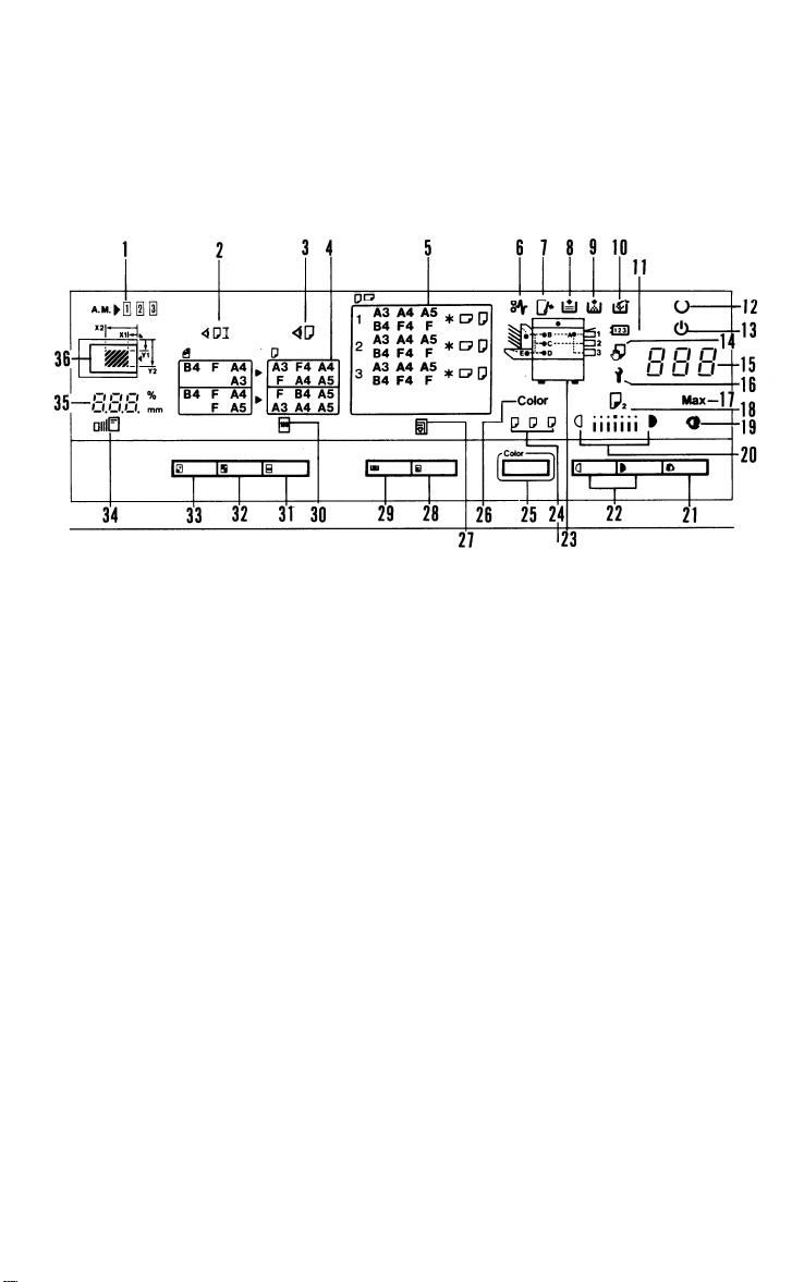
2. OPERATION PANEL
- Section A -
- LT/LDG Version -
1. Area Memory Indicator
2. Check Paper Size/Direction
3. Check Paper Size Indicator 12. Ready Indicator
4. Magnification Indicators
5. Paper Size Indicator
6. Check Paper Path Indicator
7. Close Cover Indicator
8. Load Paper Indicator
9. Add Toner Indicator
10. Used Toner Bottle Indicator
11. Set Key Counter Indicator
13. Wait Indicator
14. Manual Feed Indicator
15. Copy Counter
16. Call Service Indicator
17. Max indicator
1-4
Page 25
- A4/A3 Version -
28 February 1989
18. Second Original Indicator
19. Auto Image Density Indicator
20. Manual Image Density Indicator
21. Auto Image Density Key
22. Manual Image Density Keys
23. Misfeed Location Display
24. Color Toner Indicator
25. Color Copy Key
26. Color Copy Indicator
27. Auto Paper Select Indicator
28. Auto Paper Select Key
29.
Select Cassette Key
.
Full Size Indicator
30
.
Full Size Key
31
.
Enlarge Key
32
.
Reduce Key
33
.
Zoom Indicator
34
.
Magnification Ratio Indicator
35
.
36
Set Area Indicator
1-5
Page 26

28 February 1989
- Section B (Keys and Indicators for Special/Optional Functions) -
- LT/LDG Version -
1. Sorter Key
2. Stack Indicator
3. Sort Indicator
4. Duplex Indicators
5. Duplex Key
10.
11.
12.
6. Front Margin Adjustment Indicator 13.
7. Back Margin Adjustment Indicator
Margin Adjustment Key
8.
9.
Centering Indicator
Centering Key
Size Magnification Indicators
Size Magnification Key
Auto Reduce/Enlarge Indicator
1-6
Page 27
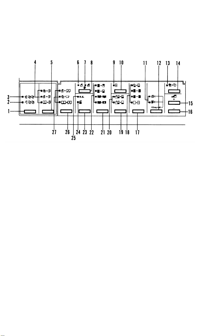
- A4/A3 Version -
28 February 1989
14. Auto Reduce/Enlarge Key
15. Zoom Up Key
16. Zoom Down Key
17. Overlay Key
18. Overlay Indicators
19. 2 Page Overlay Key
20. 2 Page Overlay Indicators
21. Edit Image Key
22. Edit Image Indicators
23. Tone Key
24. Photo Mode Indicator
25. Red Erase Indicator
26. 2 Single Copies Key
27. 2 Single Copies Indicators
1-7
Page 28

28 February 1989
- Section C -
- LT/LDG Version -
- A4/A3 Version -
1. Number Keys
2. Recall/Enter Key
3. Program Indicator
4. Program Key
5. Interrupt Indicator
6. Interrupt Key
7. Clear Modes Key
8. Start Key
9. Clear/Stop Key
1-8
Page 29
28 February 1989
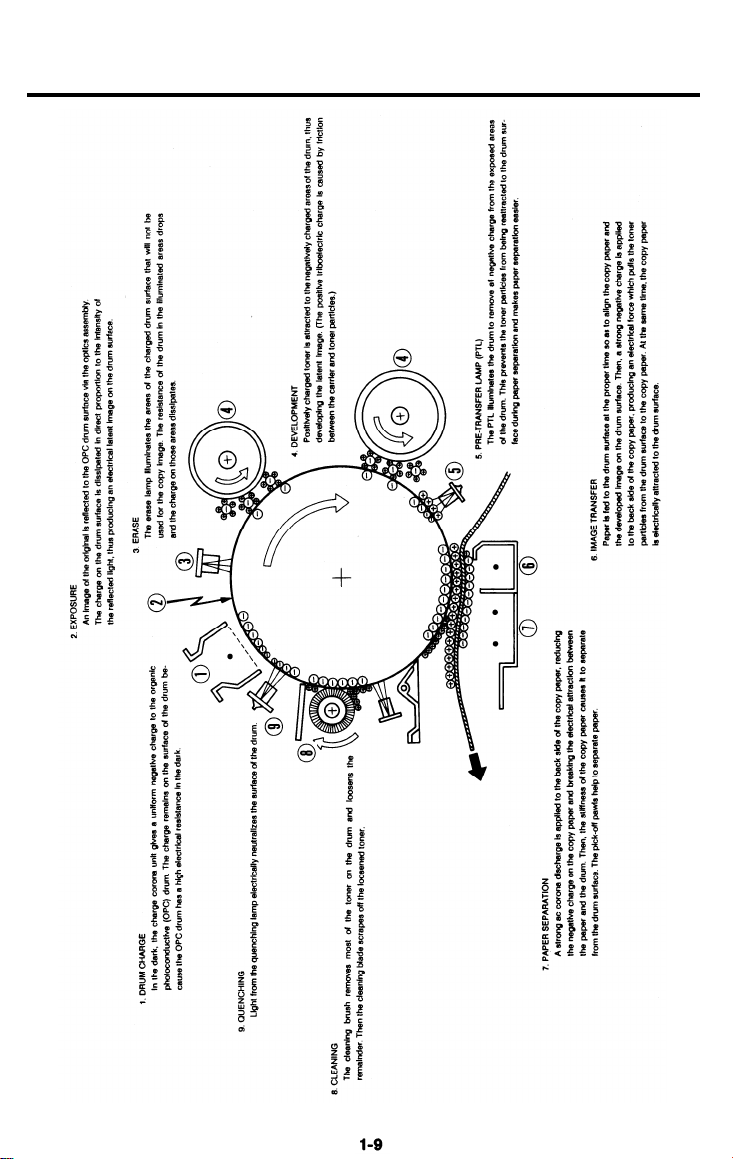
3. COPY PROCESSES AROUND THE DRUM
Page 30
28 February 1989
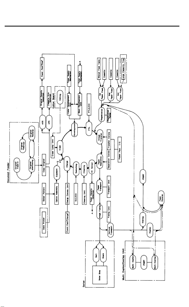
4. FUNCTIONAL OPERATION
1-10
Page 31

5. PAPER PATH
28 February 1989
The paper feed starts from one of the three paper feed
paper then follows one of two paths inside the copier.
depends on which mode the operator has selected. For copy processing, all
sheets follow the same path from the paper feed mechanism through the
fusing unit. After that, normal copies are delivered to the copy tray; however,
duplex copies and overlay copies are diverted for further processing. The fol-
lowing discussion follows the route of a single sheet of paper through a
duplex/overlay cycle.
1-11
stations. The copy
The path followed
Page 32

28 February 1989
5.1 PRIMARY
PAPER PATH
1. Paper Feed:
If paper is fed from the first station, an FRR (Feed and Reverse Roller)
mechanism separates one sheet of paper from the paper stack and feeds it to
the registration rollers. The second and third stations use a friction pad for
separation. In addition, if paper is fed from the third station, relay rollers move
the paper to the registration rollers. The registration rollers are not turning at
this time. The paper buckles slightly when the leading edge reaches the
registration rollers. Buckling seats the sheet securely between the registration
rollers and corrects any skew.
2. Registration:
At the programmed time, the registration rollers start turning to feed the paper
to the drum.
3. Image Transfer:
The toner image on the drum surface is pulled from the drum onto the pass-
ing paper by the transfer corona.
4. Paper Separation:
The electrostatic attraction between the paper and the drum is broken by the
separating corona. The suction of the vacuum fan and the weight of the paper
pulls the paper onto the transport belt. The transport belt moves the paper
with the developed copy image to the fusing unit.
5. Fusing:
The paper passes between two rollers which bond the toner image to the
paper by applying heat and pressure. At this point the copy is complete, and
the paper path splits two ways. Ordinary copies go directly through the exit
rollers to the copy tray. However, duplex copies and overlay copies are
diverted to the lower transport unit.
1-12
Page 33

5.2 SINGLE DUPLEX COPY PATH
28 February 1989
[F]:
Duplex/Overlay Transport Gate
[G]: Junction Gate
[H]: Invertor Gate
Duplex Paper Feed:
The copy paper is fed down from the fusing unit to the lower section [A],
where the paper’s leading edge passes through the inverter rollers. When the
inverter sensor detects the paper’s trailing edge, the inverter rollers [B]
reverse direction and the paper is fed to the jogger section [C]. When the
paper enters the jogger section the jogger fences move up against the paper
on both sides. Next, the transport rollers move the paper up through the vertical relay rollers [D] to the registration rollers [E]. From here on, the paper follows the same path as the first time, with the only difference being that the
reverse side now faces up to receive the image.
1-13
Page 34

28 February 1989
5.3 MULTI DUPLEX COPY PATH
Multi Duplex Paper Feed:
After the paper makes its first pass through the copier, the junction gate [A]
directs the paper to the duplex tray where jogger fences [B] move up against
the paper from both sides to correct its lateral position.
The duplex feed mechanism then feeds the paper to the jogger section inside
the copier. This time, however, the jogger fences there do not operate and
the paper is fed directly to the registration rollers.
After reaching the registration rollers, the sheet follows the same path as
when the front side was copied, with the only difference being that the
reverse side now faces up to receive the image.
1-14
Page 35

5.4 SINGLE OVERLAY COPY PATH
28 February 1989
Overlay Paper Feed:
The copy paper is fed down from the fusing unit to the lower section [A] and
sent directly to the jogger section [B]. When the paper enters the jogger sec-
tion the jogger fences move up against the paper on both sides. Next, the
transport rollers move the paper up through the vertical relay rollers [C] to the
registration rollers [D]. From here the paper follows the same path as the first
time, with the second image being placed on the same side.
1-15
Page 36

28 February 1989
5.5 MULTI OVERLAY COPY PATH
Multi Overlay Copy Feed:
After the paper makes its first pass through the copier, the junction gate [A]
directs the paper to the duplex tray, where jogger fences [B] move in from
both sides to correct the lateral position of the paper.
After this, the duplex feed mechanism feeds the paper. The inverter gate [C]
guides the paper to the inverter rollers [D]. The inverter rollers turn until the
trailing edge of the paper is detected by the inverter sensor [E]. The rollers
then reverse direction and the paper is fed to the jogger section. This time,
however, the jogger fences here do not operate and the paper is fed directly
to the registration rollers.
After the paper reaches the registration rollers, the sheet follows the same
path as when the front side was copied. However, this time the front side
faces up to make an overlay copy.
1-16
Page 37

6. DRIVE LAYOUT
28 February 1989
Gears
G1: Third Paper Feed Clutch Gear
G2: Second Paper Feed Clutch
Gear
G3: First Paper Feed Clutch Gear
G4: Toner Supply Clutch Gear
G5: Development Unit Change Drive
Gear
G6: Duplex/Overlay Transport
Clutch Gear
G7: Registration Clutch Gear
G8: Relay Clutch Gear
Sprocket
S1: Main Motor Sprocket
Timing Belt
TB1: Drum Drive Belt
Belt
B1: Exit Roller Drive Belt
Chains
C1: Main Drive Chain
C2: Duplex/Overlay Drive Chain
1-17
Page 38

28 February 1989
7. MECHANICAL COMPONENT LAYOUT
Page 39

28 February 1989
1. Exposure Lamp
2. Cleaning Unit
3. Ouenching Lamp
4. Lens
5. Charge Corona
6. 6th Mirror
7. Shield Glass
8. Erase Unit
9. Exposure Glass
10. Red Erase Unit
11. 4th Mirror
12. 5th Mirror
13. Color Development Unit
14. OPC Drum
15. Manual Feed Table
16. Black Toner Cartridge
23. Pre-Transfer Lamp
24. Registration Roller
25. Transfer Corona
26. Separation Corona
27. Pick-off Pawl
28. I.D.Sensor
29. Cleaning Brush
30. Cleaning Blade
31. Jogger Unit
32. Transport Unit
33. Main Motor
34. Pressure Roller
35. lnverter Roller
36. Inverter Gate
37. Junction Gate
38. Hot Roller
17. Black Development Unit
18. Pick-up Roller
19. Feed Roller
20. Separation Roller
21. Feed Roller
22. Friction Pad
39. Hot Roller Stripper
40. Duplex/Overlay Transport Gate
41. Fusing Exhaust Fan
42. 3rd Mirror
43. 2rd Mirror
44. 1st Mirror
1-19
Page 40

28 February 1989
8. ELECTRICAL COMPONENT LAYOUT
1. Sorter Interface Board
2. Cooling Fan Motor
3. Scanner Drive Motor
4. Main Motor Capacitor
5. Development Drive MC
6. SC Power Pack
7. Toner Supply MC
8. AC Drive Board
9. Development Unit Change SOL
10. Manual Feed Sensor
11. 1st Paper Feed MC
12. 1st Lift Motor
13. 2nd Paper Feed MC
14. Paper Feed Board
15. 1st Pick-up SOL
16. 1st Cassette Lift Sensor
17. 2nd Cassette Paper End Sensor
18. 3rd Paper Feed MC
19. I/O Control Board
20. 3rd Cassette Paper End Sensor
21. Relay Roller MC
22. Registration MC
23. Key Counter (optional)
24. 1st Cassette Paper End Sensor
25. Registration Sensor
26. Jogger Positioning SOL
27. Jogger Motor
28. Jogger H.P. Sensor
29. CC/TC Bias Power Pack
30. A3/LDG Counter (optional)
31. Total Counter
32. Red Erase SOL
33. System Control Board
34. Main SW
35. Front Cover Safety SW
36. Inverter Gate SOL
37. Noise Filter
38. Duplex/Overlay Transport Gate
SOL
39. Duplex/Overlay Transport MC
40. Pulse Generator Sensor
41. DC Power Supply Board
42. 1st Scanner H.P. Sensor
1-20
Page 41

28 February 1989
Erase Lamp
43.
Quenching Lamp
44.
45.
Auto Density Sensor
46.
Original Length Sensor
Thermal SW
47.
48.
Exposure Lamp
49.
Anti-Condensation Heater
(Optional)
50. Fusing Exhaust Fan Motor
51. Fusing Lamp
52. Fusing Exit Sensor
53. Inverter Relay Sensor
54. Inverter Sensor
55. Main Motor
56. Main Transformer
57. Lens Drive Motor
58. Drum Heater
59. Lens H.P. Sensor
60. Toner Overflow Sensor
61. Lower Relay Sensor
62. Vacuum Fan Motor
63. Upper Relay Sensor
64. 3rd Paper Size Switches
65. 2nd Paper Size Switches
66. 1st Paper Size Switches
67. ID Sensor
68. 3rd Scanner H.P. Sensor
69. 3rd Scanner Drive Motor
70. Color Toner End Sensor
71. Original Width Sensor
72. Pre-Transfer Lamp
73. Color Toner DIP SW
1-21
Page 42

28 February 1989
9. ELECTRICAL COMPONENT DESCRIPTIONS
Index
No.
Name
Motors
Main Motor
55
Fusing Exhaust
50
Fan
2
Cooling Fan
Vacuum Fan
62
Scanner Drive
3
69
3rd Scanner Drive
Lens Drive
57
27
Jogger
1st Lift Motor
12
Magnetic Clutches
22
Registration
11
1st Paper Feed
13
2nd Paper Feed
18
3rd Paper Feed
7
Toner Supply
21
Relay roller
Function
Drives all main unit components except
optics unit and fans. (100 Vac)
Removes heat from around the fusing unit.
(100 Vac)
Prevents build up of hot air in the optics
cavity. (100 Vac)
Provides suction so paper is held firmly on
the transport belt. (100 Vac)
Drives the scanner. (dc servo)
Positions the 3rd scanner. (dc stepper)
Positions the lens.
Drives the jogger plates to keep paper
evenly stacked on the jogger tray. (dc
stepper)
Lifts paper to the appropriate feed position.
Drives the registration rollers.
Starts paper feed from the first feed sta-
tion.
Starts paper feed from the second feed
station.
Starts paper feed from the 3rd feed station.
Drives toner supply roller.
Drives the relay rollers for the 3rd cas-
sette, cassette bank and the duplex/overlay paper path.
Symbol
M1
M2
M3
M4
M5
M7
M6
M8
M9
MC1
MC2
MC3
MC4
MC5
MC6
P to P
Location
H-5
H-4
H-5
F-5
D-4
D-5
D-5
F-12
F-5
F-7
F-7
F-8
F-8
F-8
F-8
5
Development Drive
Duplex/Overlay
39
Transport
15
1st Pick-up
Drives black development or color
development units
Drives the rollers of the Duplex/Overlay
section.
Starts paper feed from the 1st feed station.
1-22
MC7
MC8
SOL1
F-6
F-11
F-4
Page 43

28 February 1989
Index
No.
Development Unit
9
Change
32
Red Erase
Duplex/Overlay
38
Transport Gate
Inverter Gate
36
Jogger Positioning
26
Switches
Main
34
Front Cover Safety
35
73
Color Toner DIP
1st Paper Size
66
2nd Paper Size
65
64
3rd Paper Size
Name
Function
Changes the position of the black development unit and color development unit.
Changes the filter position.
Directs copies to the Duplex/Overlay units.
Directs copies to the Inverter Rollers.
Lifts the Jogger guide plates while copies
are being jogged.
Supplies power to the copier.
Cuts ac power line.
Indicates which color development unit is
installed.
Determines what size paper is in the first
cassette.
Determines what size paper is in the
second cassette.
Determines what size paper is in the third
cassette.
Symbol
SOL2
SOL3
SOL4
SOL5
SOL6
SW1
SW2
SW3
SW4
SW5
P to P
Location
F-4
F-5
F-11
F-12
F-12
H-2
H-2
F-3
D-10
D-10
D-10
Sensors
40
Pulse Generator
Fusing Exit
52
Toner Overflow
60
Color Toner End
70
Registration
25
Manual Feed
10
42
1st Scanner Home
Position
3rd Scanner Home
68
Position
Lens Home Posi-
59
tion
Supplies timing pulses to the system control board.
Detects misfeeds.
Detects when the used toner bottle is full.
Detects when it is time to add color toner.
Detects misfeeds.
Detects when the manual feed table is
open.
Informs the CPU when the scanner is at
the home position.
Informs the CPU when the 4th/5th mirror
assembly is in the full size position.
Informs the CPU when the lens is at the
full size position.
1-23
S1
S2
S3
S4
S5
S6
S7
S9
S8
D-2
D-6
F-3
F-3
F-8
D-12
D-4
D-4
D-5
Page 44

28 February 1989
No.
24
17
20
28
63
61
16
67
71
46
45
54
53
Name
1st Cassette Paper
End
2nd Cassette
Paper End
3rd Cassette
Paper End
Jogger Home Position
Upper Relay
Lower Relay
1st Cassette Lift
Image Density
Original Width
(OW)
Original Length
(OL)
Auto Density (AD)
Inverter
Inverter Relay
Function
Informs the CPU when the first cassette
runs out of paper.
Informs the CPU when the second cassette runs out of paper.
Informs the CPU when the third cassette
runs out of paper.
Informs the CPU when the jogger plates
are at the home position.
Detects misfeeds.
Detects misfeeds.
Detects the correct feed height of the 1st
cassette.
Detects the density of the image on the
drum.
Used for determining paper size in the
APS mode.
Used for determining paper size in the
APS mode.
Senses the background density of the
original.
Detects trailing edge of copies for inverter
roller reverse timing. Detects misfeeds.
Detects misfeeds.
Symbol
S10
S11
S12
S13
S14
S15
S16
S17
S18
S19
S20
S21
S22
P to P
Location
D-11
D-11
D-11
F-11
D-12
D-12
F-8
D-2
D-6
D-6
D-2
F-10
F-10
Thermistors
- Fusing
Power Packs
SC Power Pack
6
29 CC/TC/Bias Power
Pack
Heaters
Drum
58
Anti-condensation
49
(Option)
Monitors the fusing temperature.
Provides high voltage for the separation
corona.
Provides high voltage for the charge
corona, the development roller bias and
the transfer corona.
Prevents moisture around the drum.
Prevents moisture from forming on the op-
tics.
1-24
TH1
P1
P2
H1
H2
F-2
H-10
G-9
G-3
G-3
Page 45

28 February 1989
Index
No.
Name
Lamps
48
Exposure
Fusing
51
43
Erase
44
Quenching
72
Pre-transfer
Printed Circuit Boards
19
I/O Control
System Control
33
DC Power Supply
41
AC Drive
8
Paper Feed
14
Function Symbol
Applies high intensity light to the original
for exposure.
Provides heat to the Hot Roller.
Discharges the drum outside of the image
area. Provides leading/trailing edge erase
and editing functions.
Neutralizes any charge remaining on the
drum surface after cleaning.
Reduces charge on the drum surface
before transfer.
Interfaces the copier functions to the System Control Board. Controls the speed of
the scanner, the position of the lens, and
the position of the mirrors and AC Drive
Board.
Controls all copier functions through other
PCBs.
Rectifies 100Vac input and outputs dc volt-
age.
Drives all ac motors, the exposure lamp,
and the fusing lamp.
Receives input from paper size and paper
end sensors and sends that information to
the I/O board.
L1
L2
L3
L4
L5
PCB1
PCB2
PCB3
PCB4
PCB5
P to P
Location
H-5
H-6
D-3
F-2
F-2
E-2
C-4
G-2
G-5
C-9
Counters
Total
31
A3/LDG
30
23
Key
Keeps track of the total number of copies
made.
Keeps track of the total number of A3/11 x
17 copies made. (option)
Used for control of authorized use. Copier
will not operate until installed.
1-25
CO1
CO2
CO3
D-3
D-3
D-2
Page 46

28 February 1989
Index
No.
Name
Others
- Thermofuse
47
Thermal Switch
37
Noise Filter
4
Main Motor
Capacitor
Main Transformer
56
Function
Provides back-up overheat protection in TF
the fusing unit.
Provides back-up overheat protection
around the exposure lamp.
Removes electrical noise.
Start capacitor
Steps down the wall voltage to 100 Vac.
Symbol
TS
NF1 H-2
C H-5
TR1 H-3
P to P
Location
H-5
H-5
1-26
Page 47

28 February 1989
10. AC AND DC POWER DISTRIBUTION
The ac power supply is filtered and distributed to the fusing lamp,
heater, anticondensation heater (option), and main transformer.
The transformer supplies 100 volts to the cooling fan, fusing fan, exposure
lamp, main motor, and sorter (option). The dc power supply board receives
100 Vac from the main transformer. This voltage is rectified and regulated to
24 and 5 volts respectively. It is distributed to the ac drive board, I/O control
board, system control board, ADF, and the power packs. Vpp is an isolated
supply.
The I/O control board and system control board supply voltage to the paper
feed board, date printer (option), editor
duplex/overlay unit (option).
The LCT has a separate AC power supply,
VCC (5Vdc) from the paper feed board.
1-27
board (option), and the multi
but receives VAA (24 Vdc) and
drum
Page 48

28 February 1989
11. OVERALL MACHINE CONTROL
The following block diagram shows the flow of control signals within the
The system control board is responsible for initiating all actions that take
place in a copy cycle. The I/O control board interfaces the system control
board to those components it does not directly control.
1-28
Page 49

SECTION 2
DETAILED SECTION
DESCRIPTIONS
Page 50

CONTENTS
1. DRUM . . . . . . . . . . . . . . . . . . . . . . . . . . . . . . . . . . . . . . . . . . . . . . . . . . .2-1
1.1 OPC DRUM CHARACTERISTICS . . . . . . . . . . . . . . . . . . . . . . . . . . . . . . . . . . . . . . . . . . .2-1
1.2 HANDLING THE DRUM . . . . . . . . . . . . . . . . . . . . . . . . . . . . . . . . . . . . . . . . . . . . . . . . . . .2-2
1.3 DRUM UNIT . . . . . . . . . . . . . . . . . . . . . . . . . . . . . . . . . . . . . . . . . . . . . . . . . . . . . . . . . . . .2-3
2. DRUM CHARGE . . . . . . . . . . . . . . . . . . . . . . . . . . . . . . . . . . . . . . . . . . .2-4
2.1 OVERVIEW . . . . . . . . . . . . . . . . . . . . . . . . . . . . . . . . . . . . . . . . . . . . . . . . . . . . . . . . . . . . .2-4
2.2 CHARGE CORONA UNIT . . . . . . . . . . . . . . . . . . . . . . . . . . . . . . . . . . . . . . . . . . . . . . . . .2-5
2.3 CHARGE CORONA POWER PACK . . . . . . . . . . . . . . . . . . . . . . . . . . . . . . . . . . . . . . . . .2-6
2.4 CHARGE CORONA WIRE CLEANER MECHANISM . . . . . . . . . . . . . . . . . . . . . . . . . . . .2-7
3. OPTICS . . . . . . . . . . . . . . . . . . . . . . . . . . . . . . . . . . . . . . . . . . . . . . . . . .2-8
3.1 OVERVIEW . . . . . . . . . . . . . . . . . . . . . . . . . . . . . . . . . . . . . . . . . . . . . . . . . . . . . . . . . . . . .2-8
3.2 SCANNER DRIVE . . . . . . . . . . . . . . . . . . . . . . . . . . . . . . . . . . . . . . . . . . . . . . . . . . . . . . .2-9
3.2.1 1st and 2nd Scanner Drive Mechanism . . . . . . . . . . . . . . . . . . . . . . . . . . . . . . . . .2-9
3.3 SCANNER MOTOR DRIVE . . . . . . . . . . . . . . . . . . . . . . . . . . . . . . . . . . . . . . . . . . . . . . .2-10
3.4 LENS DRIVE . . . . . . . . . . . . . . . . . . . . . . . . . . . . . . . . . . . . . . . . . . . . . . . . . . . . . . . . . .2-11
3.4.1 Lens Drive . . . . . . . . . . . . . . . . . . . . . . . . . . . . . . . . . . . . . . . . . . . . . . . . . . . . . . . .2-11
3.4.2 Shading Mechanism . . . . . . . . . . . . . . . . . . . . . . . . . . . . . . . . . . . . . . . . . . . . . . . .2-11
3.5 LENS POSlTIONING . . . . . . . . . . . . . . . . . . . . . . . . . . . . . . . . . . . . . . . . . . . . . . . . . . . .2-12
3.6 3RD SCANNER DRIVE . . . . . . . . . . . . . . . . . . . . . . . . . . . . . . . . . . . . . . . . . . . . . . . . . .2-13
3.6.1 Drive . . . . . . . . . . . . . . . . . . . . . . . . . . . . . . . . . . . . . . . . . . . . . . . . . . . . . . . . . . . . .2-13
3.6.2 Positioning . . . . . . . . . . . . . . . . . . . . . . . . . . . . . . . . . . . . . . . . . . . . . . . . . . . . . . . .2-13
3.7 STEPPER MOTOR CONTROL . . . . . . . . . . . . . . . . . . . . . . . . . . . . . . . . . . . . . . . . . . . .2-14
3.8 RED ERASE MECHANISM . . . . . . . . . . . . . . . . . . . . . . . . . . . . . . . . . . . . . . . . . . . . . . .2-15
3.9 AUTOMATlC lMAGE DENSITY SENSlNG . . . . . . . . . . . . . . . . . . . . . . . . . . . . . . . . . . .2-16
3.10 AUTOMATIC ORIGINAL SIZE DETECTION . . . . . . . . . . . . . . . . . . . . . . . . . . . . . . . . .2-17
3.11 EXPOSURE LAMP VOLTAGE CORRECTION . . . . . . . . . . . . . . . . . . . . . . . . . . . . . . .2-18
3.11.1 Manual Image Density Correction . . . . . . . . . . . . . . . . . . . . . . . . . . . . . . . . . . . .2-18
3.11.2 Size Magnification Correction . . . . . . . . . . . . . . . . . . . . . . . . . . . . . . . . . . . . . . . .2-18
3.11.3 Drum Sensitivity Correction (Vr Correction) . . . . . . . . . . . . . . . . . . . . . . . . . . . . .2-19
3.11.4 Drum Rotation Correction . . . . . . . . . . . . . . . . . . . . . . . . . . . . . . . . . . . . . . . . . . .2-19
3.11.5 Photo Mode Correction . . . . . . . . . . . . . . . . . . . . . . . . . . . . . . . . . . . . . . . . . . . . .2-20
3.11.6 ADS Correction (SP mode #34) . . . . . . . . . . . . . . . . . . . . . . . . . . . . . . . . . . . . . .2-20
Page 51

3.11.7 Red Erase Mode Correction . . . . . . . . . . . . . . . . . . . . . . . . . . . . . . . . . . . . . . . . .2-20
3.11.8 Pre-scan Correction . . . . . . . . . . . . . . . . . . . . . . . . . . . . . . . . . . . . . . . . . . . . . . .2-20
3.12 EXPOSURE LAMP CONTROL ClRCUlT . . . . . . . . . . . . . . . . . . . . . . . . . . . . . . . . . . . .2-21
3.13 SERVICE CALL CONDITIONS . . . . . . . . . . . . . . . . . . . . . . . . . . . . . . . . . . . . . . . . . .2-22
4. ERASE . . . . . . . . . . . . . . . . . . . . . . . . . . . . . . . . . . . . . . . . . . . . . . . . .2-24
4.1 OVERVIEW . . . . . . . . . . . . . . . . . . . . . . . . . . . . . . . . . . . . . . . . . . . . . . . . . . . . . . . . . . . .2-24
4.1.1 Lead Edge Erase . . . . . . . . . . . . . . . . . . . . . . . . . . . . . . . . . . . . . . . . . . . . . . . . . . .2-25
4.1.2 Side Erase . . . . . . . . . . . . . . . . . . . . . . . . . . . . . . . . . . . . . . . . . . . . . . . . . . . . . . . .2-25
4.1.3 Special Mode Erase . . . . . . . . . . . . . . . . . . . . . . . . . . . . . . . . . . . . . . . . . . . . . . . .2-26
4.1.4 Trailing Edge Erase . . . . . . . . . . . . . . . . . . . . . . . . . . . . . . . . . . . . . . . . . . . . . . . . .2-26
4.2 ERASE LAMP CIRCUIT . . . . . . . . . . . . . . . . . . . . . . . . . . . . . . . . . . . . . . . . . . . . . . . . . .2-27
4.3 ERASE TIMING . . . . . . . . . . . . . . . . . . . . . . . . . . . . . . . . . . . . . . . . . . . . . . . . . . . . . . . .2-28
5. DEVELOPMENT . . . . . . . . . . . . . . . . . . . . . . . . . . . . . . . . . . . . . . . . . .2-29
5.1 OVERVIEW . . . . . . . . . . . . . . . . . . . . . . . . . . . . . . . . . . . . . . . . . . . . . . . . . . . . . . . . . . . .2-29
5.2 DEVELOPMENT UNIT CHANGE MECHANISM . . . . . . . . . . . . . . . . . . . . . . . . . . . . . . .2-30
5.3 DEVELOPMENT UNIT SUPPORT MECHANISM . . . . . . . . . . . . . . . . . . . . . . . . . . . . . .2-31
5.4 DRIVE MECHANISM (Black) . . . . . . . . . . . . . . . . . . . . . . . . . . . . . . . . . . . . . . . . . . . . . .2-32
5.5 DRIVE MECHANISM (Color) . . . . . . . . . . . . . . . . . . . . . . . . . . . . . . . . . . . . . . . . . . . . . .2-33
5.6 AGITATOR MECHANISM . . . . . . . . . . . . . . . . . . . . . . . . . . . . . . . . . . . . . . . . . . . . . . . .2-34
5.7 TONER SUPPLY AND AGITATOR DRIVE MECHANISM . . . . . . . . . . . . . . . . . . . . . . . .2-35
5.8 TONER DENSITY DETECTION . . . . . . . . . . . . . . . . . . . . . . . . . . . . . . . . . . . . . . . . . . . .2-36
5.9 TONER DENSITY CONTROL . . . . . . . . . . . . . . . . . . . . . . . . . . . . . . . . . . . . . . . . . . . . .2-37
5.10 TONER END DETECTION (Black) . . . . . . . . . . . . . . . . . . . . . . . . . . . . . . . . . . . . . . . .2-38
5.10.1 Black . . . . . . . . . . . . . . . . . . . . . . . . . . . . . . . . . . . . . . . . . . . . . . . . . . . . . . . . . . .2-38
5.11 TONER END DETECTION (Color) . . . . . . . . . . . . . . . . . . . . . . . . . . . . . . . . . . . . . . . .2-39
5.11.1 Color . . . . . . . . . . . . . . . . . . . . . . . . . . . . . . . . . . . . . . . . . . . . . . . . . . . . . . . . . . .2-39
5.12 ID SENSOR SUPPLY CONTROL (Black only) . . . . . . . . . . . . . . . . . . . . . . . . . . . . . . .2-40
5.13 ID SENSOR TONER SUPPLY LEVEL . . . . . . . . . . . . . . . . . . . . . . . . . . . . . . . . . . . . . .2-41
5.14 ID SENSOR SUPPLY CONTROL IN FIXED SUPPLY MODE . . . . . . . . . . . . . . . . . . . .2-42
5.15 TONER SUPPLY AMOUNT (FIXED SUPPLY MODE) . . . . . . . . . . . . . . . . . . . . . . . . .2-44
5.16 ID SENSOR ERROR DETECTION . . . . . . . . . . . . . . . . . . . . . . . . . . . . . . . . . . . . . . . .2-45
5.17 DEVELOPMENT BlAS CONTROL . . . . . . . . . . . . . . . . . . . . . . . . . . . . . . . . . . . . . . . .2-46
5.17.1 Manual bias control . . . . . . . . . . . . . . . . . . . . . . . . . . . . . . . . . . . . . . . . . . . . . . . .2-46
5.17.2 Auto Image Density bias control . . . . . . . . . . . . . . . . . . . . . . . . . . . . . . . . . . . . . .2-46
Page 52

5.18 BIAS CORRECTION . . . . . . . . . . . . . . . . . . . . . . . . . . . . . . . . . . . . . . . . . . . . . . . . . . .2-47
5.18.1 Vr Correction . . . . . . . . . . . . . . . . . . . . . . . . . . . . . . . . . . . . . . . . . . . . . . . . . . . . .2-47
5.18.2 SP Mode Correction . . . . . . . . . . . . . . . . . . . . . . . . . . . . . . . . . . . . . . . . . . . . . . .2-47
5.19 ID SENSOR BIAS COMPENSATION . . . . . . . . . . . . . . . . . . . . . . . . . . . . . . . . . . . . . .2-48
5.19.1 Standard Bias . . . . . . . . . . . . . . . . . . . . . . . . . . . . . . . . . . . . . . . . . . . . . . . . . . . .2-48
5.19.2 Vp Correction . . . . . . . . . . . . . . . . . . . . . . . . . . . . . . . . . . . . . . . . . . . . . . . . . . . .2-48
5.19.3 Developer Counter Correction . . . . . . . . . . . . . . . . . . . . . . . . . . . . . . . . . . . . . . .2-49
5.19.4 Total lD Sensor Bias . . . . . . . . . . . . . . . . . . . . . . . . . . . . . . . . . . . . . . . . . . . . . . .2-49
6. IMAGE TRANSFER . . . . . . . . . . . . . . . . . . . . . . . . . . . . . . . . . . . . . .2-50
6.1 PRE-TRANSFER LAMP (PTL) . . . . . . . . . . . . . . . . . . . . . . . . . . . . . . . . . . . . . . . . . . . . .2-50
6.2 IMAGE TRANSFER . . . . . . . . . . . . . . . . . . . . . . . . . . . . . . . . . . . . . . . . . . . . . . . . . . . . .2-50
6.3 PAPER SEPARATION AND TRANSPORT . . . . . . . . . . . . . . . . . . . . . . . . . . . . . . . . . . .2-51
6.3.1 Paper Separation . . . . . . . . . . . . . . . . . . . . . . . . . . . . . . . . . . . . . . . . . . . . . . . . . . .2-51
6.3.2 Paper Transport . . . . . . . . . . . . . . . . . . . . . . . . . . . . . . . . . . . . . . . . . . . . . . . . . . . .2-51
6.4 PTL AND T/S CHARGE CIRCUIT . . . . . . . . . . . . . . . . . . . . . . . . . . . . . . . . . . . . . . . . . .2-52
7. ID SENSOR . . . . . . . . . . . . . . . . . . . . . . . . . . . . . . . . . . . . . . . . . . .2-53
7.1 ID SENSOR IMAGE CORRECTION (Vr Pattern) . . . . . . . . . . . . . . . . . . . . . . . . . . . . . .2-53
7.2 ID SENSOR PATTERN (Vsp) . . . . . . . . . . . . . . . . . . . . . . . . . . . . . . . . . . . . . . . . . . . . .2-55
8. DRUM CLEANING . . . . . . . . . . . . . . . . . . . . . . . . . . . . . . . . . . . . . . .2-56
8.1 OVERVIEW . . . . . . . . . . . . . . . . . . . . . . . . . . . . . . . . . . . . . . . . . . . . . . . . . . . . . . . . . . .2-56
8.2 DRIVE MECHANISM . . . . . . . . . . . . . . . . . . . . . . . . . . . . . . . . . . . . . . . . . . . . . . . . . . . .2-57
8.3 RELEASE MECHANISM . . . . . . . . . . . . . . . . . . . . . . . . . . . . . . . . . . . . . . . . . . . . . . . . .2-58
8.4 TONER OVERFLOW DETECTION . . . . . . . . . . . . . . . . . . . . . . . . . . . . . . . . . . . . . . . . .2-59
9. PAPER FEED AND REGISTRATION . . . . . . . . . . . . . . . . . . . . . . . . .2-60
9.1 OVERVIEW . . . . . . . . . . . . . . . . . . . . . . . . . . . . . . . . . . . . . . . . . . . . . . . . . . . . . . .2-60
9.2 FRR FEED SYSTEM . . . . . . . . . . . . . . . . . . . . . . . . . . . . . . . . . . . . . . . . . . . . . . . . . . . .2-61
9.2.1 Pick-up Roller . . . . . . . . . . . . . . . . . . . . . . . . . . . . . . . . . . . . . . . . . . . . . . . . . . . . .2-61
9.2.2 Feed and Separation Rollers . . . . . . . . . . . . . . . . . . . . . . . . . . . . . . . . . . . . . . . . .2-61
9.3 FRICTION PAD FEED SYSTEM . . . . . . . . . . . . . . . . . . . . . . . . . . . . . . . . . . . . . . . . . . .2-62
9.4 PAPER LlFT MECHANlSM (1st Feed Station) . . . . . . . . . . . . . . . . . . . . . . . . . . . . . . . .2-63
9.5 PAPER LlFT MECHANlSM (2nd and 3rd Feed Stations) . . . . . . . . . . . . . . . . . . . . . . . .2-64
9.6 PAPER SIZE AND END DETECTION . . . . . . . . . . . . . . . . . . . . . . . . . . . . . . . . . . . . . . .2-65
9.7 PAPER FEED DRIVE MECHANISM (FRR) . . . . . . . . . . . . . . . . . . . . . . . . . . . . . . . . . . .2-66
9.8 PAPER FEED REGlSTRATION DRlVE MECHANISM . . . . . . . . . . . . . . . . . . . . . . . . . .2-67
Page 53

9.9 MANUAL FEED TABLE . . . . . . . . . . . . . . . . . . . . . . . . . . . . . . . . . . . . . . . . . . . . . . . . . .2-68
9.10 PAPER FEED TlMlNG . . . . . . . . . . . . . . . . . . . . . . . . . . . . . . . . . . . . . . . . . . . . . . . . . .2-69
9.11 SERVlCE CALL CONDITION . . . . . . . . . . . . . . . . . . . . . . . . . . . . . . . . . . . . . . . . . . . .2-70
10. IMAGE FUSING AND PAPER EXIT . . . . . . . . . . . . . . . . . . . . . . . . . .2-71
10.1 OVERVIEW . . . . . . . . . . . . . . . . . . . . . . . . . . . . . . . . . . . . . . . . . . . . . . . . . . . . . . . . . . .2-71
10.2 FUSING DRIVE RELEASE MECHANISM . . . . . . . . . . . . . . . . . . . . . . . . . . . . . . . . . . .2-72
10.3 FUSING CONTROL . . . . . . . . . . . . . . . . . . . . . . . . . . . . . . . . . . . . . . . . . . . . . . . . . . . .2-73
10.3.1 Phase Control . . . . . . . . . . . . . . . . . . . . . . . . . . . . . . . . . . . . . . . . . . . . . . . . . . . .2-74
10.4 SERVlCE CALL CONDlTIONS . . . . . . . . . . . . . . . . . . . . . . . . . . . . . . . . . . . . . . . . . . .2-75
11. DUPLEX/OVERLAY MECHANISM . . . . . . . . . . . . . . . . . . . . . . . . . . .2-76
11.1 OVERVIEW . . . . . . . . . . . . . . . . . . . . . . . . . . . . . . . . . . . . . . . . . . . . . . . . . . . . . . . . . . .2-76
11.2 DRIVE MECHANISM . . . . . . . . . . . . . . . . . . . . . . . . . . . . . . . . . . . . . . . . . . . . . . . . . . .2-77
11.3 JOGGER MECHANISM . . . . . . . . . . . . . . . . . . . . . . . . . . . . . . . . . . . . . . . . . . . . . . . . .2-78
11.4 SlNGLE DUPLEX/OVERLAY TIMING . . . . . . . . . . . . . . . . . . . . . . . . . . . . . . . . . . . . . .2-79
12. OTHERS . . . . . . . . . . . . . . . . . . . . . . . . . . . . . . . . . . . . . . . . . . . . . . .2-80
12.1 PAPER MISFEED CHECK . . . . . . . . . . . . . . . . . . . . . . . . . . . . . . . . . . . . . . . . . . . . . . .2-80
12.2 SERVICE CALL CONDlTIONS (Others) . . . . . . . . . . . . . . . . . . . . . . . . . . . . . . . . . . . .2-82
13. COPIER TIMING CHART . . . . . . . . . . . . . . . . . . . . . . . . . . . . . . . . . .2-83
Page 54

28 February 1989
1. DRUM
1.1 OPC DRUM CHARACTERISTICS
An OPC has the characteristics of:
•
Being able to accept a high negative electrical charge in the dark. (The
electrical resistance of a photoconductor is high in the absence of light.)
Dissipating the electrical charge when exposed to light. (Exposure to light
•
greatly increases the conductivity of a photoconductor.)
Dissipating an amount of charge in direct proportion to the intensity of the
•
light. That is, where stronger light is directed to the photoconductor
surface, a smaller voltage remains on the OPC.
Being less sensitive to changes in temperature (when compared to
selenium F type drums). This makes it unnecessary to monitor and control
the drum temperature.
2-1
Page 55

28 February 1989
1.2 HANDLING THE DRUM
The organic photoconductor drum is comparatively more sensitive to light,
and ammonia gas than a selenium drum.
1. Never expose the drum to direct sunlight.
2. Never expose the drum to direct light of more than 1000 Lux for more
than a minute.
3. Never touch the drum surface with bare hands. When the drum surface is
touched with a finger or becomes dirty, wipe with a dry cloth or clean with
wet cotton. Wipe with a dry cloth after cleaning with wet cotton.
4. Never use alcohol to clean the drum; alcohol dissolves the drum surface.
5. Store the drum in a cool, dry place away from heat.
6. Take care not to scratch the drum as the drum layer is thin and is easily
damaged.
7. Never expose the drum to corrosive gases such as ammonia gas.
8. Always keep the drum in the protective sheet when inserting or pulling the
drum out of the copier.
9. Before inserting or pulling out the drum, remove all units around the drum.
2-2
Page 56

1.3 DRUM UNIT
28 February 1989
An organic photoconductor drum [A] is used on this model.
A drum unit [B] is used to hold the drum to prevent stress on the drum. The
drum unit consists of an OPC drum, ID sensor [C] and separation pawls [D].
The drum is driven by the main motor [H] through the drum drive belt [E] and
the drum drive gear [F]. The separation pawls [D] are always in contact with
the drum surface. The ID sensor is electrically connected to the ID sensor
connector [G].
2-3
Page 57

28 February 1989
2. DRUM CHARGE
2.1 OVERVIEW
This copier uses a single wire scorotron and a highly sensitive OPC drum.
The corona wire [A] generates a corona of negative ions when the charge
power pack applies a high voltage (-5.0 to -7.5 KV). The drum coating [B]
receives a uniform negative charge as it rotates past the corona unit.
A stainless steel grid plate [C] makes the corona charge uniform. The charge
fan [D] provides a smooth flow of air to the interior of the charge corona unit
to prevent an uneven build up of negative ions. (An uneven build up of negative ions could cause uneven image density.)
2-4
Page 58

2.2 CHARGE CORONA UNIT
28 February 1989
The charge corona unit consists of the charge corona wire [A], the grid mesh
[B] and the charge wire cleaner [C].
The applied voltage of the charge corona wire is constant but the surface
potential of the drum rises in proportion to the number of copies made. A voltage corresponding to the drum surface potential is applied to the grid [B] to
achieve consistent copy quality. The amount of compensation is determined
by the ID sensor (Vrp/Vsg).
The flow of air around the charge corona wire [A] may deposit paper dust or
toner particles on the corona wire. These particles may interfere with charging
and cause low density bands on copies. The wire cleaner [C] cleans the
corona wire when the operator slides the corona unit in and out.
2-5
Page 59

21 April 1989
2.3 CHARGE CORONA POWER PACK
The circuit operation for the charge corona begins with the input of 24 volts to
the power pack at CN1-1. This power supply is used for the high voltage
corona.
The charge corona turns on 0.1 seconds after the Start key is pressed.
A LOW signal from the I/O control board (at CN1-3) energizes the power
pack. The OFF timing is the same as the scanner return timing.
The grid voltage is also applied by the power pack. The voltage for the ID
sensor grid is -560 volts. This ID sensor grid is applied from 0.1 to 0.59
seconds after the Start key is pressed.
The voltage for the image grid changes depends on the combination of G0 G3 (Vrp/Vsg).
2-6
Page 60

28 February 1989
2.4 CHARGE CORONA WIRE CLEANER MECHANISM
Pads [A] above and below the charge corona wire clean the wire as the
charge unit is manually slid in and out.
The cleaner pad bracket [B] rotates when the charge unit is fully extended
and the bracket is pulled up against the rear block [C]. This moves the pads
against the corona wire (see illustration).
The pads move away from the wire when the charge unit is fully inserted and
the cleaning bracket is pushed against the front block [D].
2-7
Page 61

28 February 1989
3. OPTICS
3.1 OVERVIEW
During the copy cycle, an image of the original is reflected onto the drum sur-
face via the optics assembly as follows.
Light Path:
Exposure Lamp [A]
–> 2nd Mirror [D] –> 3rd Mirror [E] –> Lens [F]
–> 4th Mirror [G]
–> 6th Mirror [J]
The cooling fan [M] removes warm air (heated by the exposure lamp) from
the optics cavity. This blower operates during every copy cycle.
The 1st scanner (lamp and 1st mirror), 2nd scanner (2nd and 3rd mirrors),
3rd scanner (4th and 5th mirrors), and the lens function together to achieve a
wide range of reproduction ratios.
The red erase unit [I] has a green filter and a red filter. The green filter is used
in the normal copy mode. The red filter is used in the red erase copy mode.
Auto density sensing (ADS) and auto original paper size sensing (APS) are
done by optical fibers located on the 1st scanner unit.
A thermoswitch (opens at 130°C)installed on the back of the exposure lamp
reflector keeps temperatures at acceptable levels inside the optics assembly.
–> Original [B]
–> 5th Mirror [H] –> Red erase [I] –>
–> Toner shield glass [K] –>
–> 1st mirror [C] –>
Drum [L]
2-8
Page 62

28 February 1989
3.2 SCANNER DRIVE
3.2.1 1st and 2nd Scanner Drive Mechanism
This model uses a dc servo motor [A] to drive the scanners. Both ends of
each scanner are driven to prevent skewing. The scanners have sliders [B],
which ride on guide rails.
The scanner home position is detected by the home position sensor [C]. The
scanner return position is detected by counting the scanner motor drive pulses.
The first scanner [D], which consists of the exposure lamp and the first mirror,
is connected to the scanner drive wire by the wire clamps [E]. The second
scanner [F], which consists of the second and third mirrors, is connected to
the scanner drive wire by movable pulleys (the second scanner pulley [G]).
The pulley moves the second scanner at half the velocity of the first scanner.
This is to maintain the focal distance between the original and the lens during
scanning. This relationship can be expressed as:
V1r =
where r =
V1r =
2(V2r) = VD/r
Reproduction ratio
First scanner velocity (when the reproduction
ratio is “r”)
V2r =
Second scanner velocity (when the reproduction
ratio is “r”)
VD
=
Drum peripheral velocity (120 mm/s)
2-9
Page 63

28 February 1989
3.3 SCANNER MOTOR DRIVE
The scanner drive motor is a servomotor. The I/O control PCB controls the
speed of this servomotor. The I/O control PCB and the system control PCB
communicate through a serial interface.
At the programmed time, the system control PCB checks the drum speed by
monitoring the pulses from the pulse generator. Based on this input, the I/O
control PCB determines the proper speed for the scanner drive motor.
The encoder on the servomotor is a photointerruptor that generates pulse
signals. The I/O control PCB monitors the scanner speed by these pulse signals and uses this data to regulate the servomotor speed.
The home position sensor informs the I/O control PCB when the first scanner
is in the home position.
2-10
Page 64

3.4 LENS DRIVE
28 February 1989
: Reduction
: Enlargement
3.4.1 Lens Drive
The lens drive motor [A] (stepper motor) changes the lens [B] position
through the lens drive wire [C] in accordance with the selected reproduction
ratio to provide the proper optical distance between the lens and the drum
surface.
The rotation of the lens drive pulley moves the lens back and forth in discrete
steps. The home position of the lens is detected by the home position sensor
[D]. The I/O control PCB keeps track of the lens position based on the number of pulses sent to the lens drive motor.
3.4.2 Shading Mechanism
The shading plates [E] are installed on the lens housing [F] and are slid open
and shut by the shading cam [G]. This shading mechanism adjusts the
horizontal light intensity, which becomes uneven in reduction mode, when the
light at both edges is more intense. The shading plates close in reduction
mode to even out the light intensity.
2-11
Page 65

28 February 1989
3.5 LENS POSITIONING
: Reduction
: Enlargement
The lens home position sensor [A] informs the I/O control PCB when the lens
is at full size position (home position). The I/O control PCB determines the
lens stop position in reduction and enlargement modes by counting the num-
ber of steps the motor makes with reference to the lens home position. When
a new reproduction ratio is selected, the lens [B] moves directly to the
selected magnification position.
The lens home position is registered each time the lens starts from or passes
through the lens home position sensor. As the lens moves from right to left
(as viewed from the front), the sensor registers the home position. This oc-
curs when the actuator plate [C] enters the lens home position sensor.
A small vibration can be observed when the lens moves through home position from enlargement to reduction because the lens is going in the wrong
direction to register. The lens overshoots the home position by only one pulse
before going back to reference the home position.
The lens always stops while moving from left to right to minimize the error
caused by mechanical play in the drive gears [D].
2-12
Page 66

3.6 3RD SCANNER DRIVE
28 February 1989
3.6.1 Drive
The 3rd scanner drive motor (stepper motor) changes the 3rd scanner position through the drive wire [A] in accordance with the selected reproduction
ratio to provide the proper optical distance between the lens and drum surface.
3.6.2 Positioning
The positioning mechanism is similar to that of lens positioning, as shown in
the above positioning chart. The scanner always stops while moving from left
to right (as viewed from the front).
2-13
Page 67

28 February 1989
3.7 STEPPER MOTOR CONTROL
Both the lens drive motor and the third scanner drive motor are stepper
motors. The stators of these stepper motors have four coils (labeled A, B,
and above), and the rotors are permanent magnets.
Pulse signals energize the four coils as shown in the above illustration. The
rotor turns in discrete steps.
2-14
Page 68

3.8 RED ERASE MECHANISM
28 February 1989
This model has a red erase function. In red erase mode, the red erase
solenoid [A] is energized (ON) to move the red filter [B] into the optical path.
(Normally, the green filter [C] is in the optical path.)
The red filter allows only red to pass through, thus decreasing the contrast in
light intensity between the red and white areas on the original.
2-15
Page 69

23 May 1989
3.9 AUTOMATIC IMAGE DENSITY SENSING
The input for the automatic image density circuit is via a fiber optic cable [A]
mounted on the first scanner. Light from the exposure lamp [B] passes
through a small hole in the reflector, reflects from the original, and is collected
by the fiber optic cable. The sampled strip starts 18 millimeters from the lead-
ing edge of the original.
The detecting length L of the ADS circuit is determined by the following equa-
tion in each copy mode:
88 mm
Black copy mode: L =
Reproduction Ratio
44 mm
Color copy mode: L =
Reproduction Ratio
The highest voltage detected by the ADS is held (peak hold) and used for the
bias voltage adjustment. The ADS system will change the developer bias to
adjust the image density for optimum copy quality. This ADS system has
three base levels (N,D,L) to allow the system more flexibility. SP Mode #34
switches the settings as follows:
N: Normal (base levels)
D: Dark (no exposure lamp change, bias increases 40V)
L: Light (2V exposure lamp voltage increase, no bias increase)
2-16
Page 70

3.10 AUTOMATIC ORIGINAL SIZE DETECTION
28 February 1989
The original length sensor [A] and width sensor [B] on the first scanner detect
the original size during pre-scanning.
Length and width sensor data are combined as shown in the size detection
table to determine the original size.
The pre-scan speed is one half of the normal scan speed.
2-17
Page 71

28 February 1989
3.11 EXPOSURE LAMP VOLTAGE CORRECTION
3.11.1 Manual Image Density Correction
The I/O control PCB controls the exposure lamp voltage based on the manual
image density level (selected using the operation panel image density key)
and ADS base level. Lamp voltage at level 4 in manual image density mode
can be set to 50 to 75 V using SP mode #48 (Standard 64 V). The following
inputs will also change the lamp voltage to ensure consistent copy quality.
Lamp voltage is varied by pressing the manual image density key on the control panel to adjust the image density.
3.11.2 Size Magnification Correction
Lamp voltage is varied pressing the magnification key of the control panel to
compensate for the change in the concentration of light on the drum.
2-18
Page 72

28 February 1989
3.11.3 Drum Sensitivity Correction (Vr correction)
As the OPC drum is used, residual voltage rises gradually in repeat copying
due to characteristics of the drum. The lamp voltage is adjusted to keep copy
quality consistent.
3.11.4 Drum Rotation Correction
To compensate for fogging of the OPC drum surface by the cleaning brush,
main motor “on” time is tracked and lamp voltage increased accordingly.
2-19
Page 73

28 February 1989
3.11.5 Photo Mode Correction
S P Mode #40
setting Data
Normal N(0)
Lighter L(1)
Darker D(2)
Correcting Voltage
-2V
±0V
-4V
When photo mode is selected, the image density level can only be changed
manually and the lamp voltage is shifted by -2V from the standard voltage in
normal mode (V0). The amount of shift can be changed with SP mode #40.
(Auto density cannot be used.)
3.11.6 ADS Correction (SP mode #34)
Users can vary the voltage in ADS mode using SP mode #34. Normally this is
a standard set voltage (V0).
3.11.7 Red Erase Mode Correction
The voltage is raised by +2V when red erase mode is selected. (V0 + 2V)
3.11.8 Pre-scan Correction
The voltage is fixed to 68V during pre-scan when Auto Paper Select is
selected.
2-20
Page 74

3.12 EXPOSURE LAMP CONTROL CIRCUIT
AC power
Zero cross
28 February 1989
Trigger pulse
Lamp power
Feedback signal
The I/O control board sends lamp trigger pulses to the ac drive board from
CN304-A19. PC401 activates TRC401, which provides ac power to the exposure lamp at the trailing edge of each trigger pulse.
The voltage applied to the exposure lamp is also provided to the feedback cir-
cuit. The feedback circuit steps down (T401), rectifies (DB405), and smoothes
(zener diodes and capacitors) the lamp voltage. The CPU monitors the lowest
point of the smoothed wave (feedback signal). The lowest point of this signal
is directly proportional to the actual lamp voltage.
In case of overheating, the thermoswitch opens at 130°C and removes ac
power to the exposure lamp.
2-21
Page 75

28 February 1989
3.13 SERVICE CALL CONDITIONS
Self Diagnostic Code 11:
Code 11 is displayed if a lamp circuit malfunction is detected during standby
(lamp ON), or if the lamp filament or thermal switch opens.
Self Diagnostic Code 12:
Exposure Lamp Malfunction
Code 12 is displayed if the lamp circuit malfunctions (stays ON), or if the lamp
filament or thermal switch opens for longer than 20 seconds during a copy
cycle.
Self Diagnostic Code 21:
Scanner Malfunction
Code 21 is displayed if the 1st scanner home position sensor is not actuated
within 6 seconds (scanner does not return home).
Self Diagnostic Code 22:
Scanner Malfunction
Code 22 is displayed if the 1st scanner home position sensor remains ac-
tuated (OFF) during the initialization.
Self Diagnostic Code 23:
Code 23 is displayed if the I/O control board does not receive the registration
start signal within 4.9 seconds after the scanner starts.
Self Diagnostic Code 24:
No Scanner Home Position Signal
Code 24 is displayed if the I/O control board does not detect the home posi-
tion signal within 20 seconds after the scanner starts. (The scanner does not
return to the home position.)
2-22
Page 76

28 February 1989
Self Diagnostic Code 25:
Code 25 is displayed if the scanner motor encoder pulse phase is not
detected.
Self Diagnostic Code 2E
Scanner Motor Malfunction
Code 2E is displayed if the scanner motor encoder pulse is not detected for
more than 100m seconds.
Self Diagnostic Codes 2A and 2B:
Third Scanner Home Position
At certain times (power ON, clear, auto-reset), the third scanner either moves
to its home position or moves out and back. Code 2A is displayed if the third
scanner home position sensor stays OFF longer than 2.3 seconds. Code 2B
is displayed if the third scanner home position sensor stays ON longer than
2.3 seconds.
Self Diagnostic Codes 28 and 29:
Lens Home Position Check
Code 28 is displayed if the lens home position sensor stays OFF (high). Code
29 is displayed if the scanner home position sensor stays ON (low).
2-23
Page 77

28 February 1989
4. ERASE
4.1 OVERVIEW
LE:
Lead edge erase margin 2.5 ± 1.5 mm
SE
: Side erase margin
Lo:
Original width
Lc:
Charged width of drum
EL:
Lead edge erase
ES:
Side erase
The erase lamp [A] consists of a line of 120 LEDs extending across the 300
mm width of the drum [C].
The function of the erase lamp is to prevent the toner from being attracted to
the non-image part of the drum and to reduce the load on the cleaning unit.
The erase function is divided into three major erase functions: lead edge
erase, side erase, and editing mode erase.
1.5 ± 1.5 mm on each side;
total of both sides 4 mm or less
2-24
Page 78

28 February 1989
ERASE LAMP TIMING
4.1.1 Lead Edge Erase
The entire line of LEDs turns on when the main motor turns on. They stay on
until the erase margin slightly overlaps the lead edge of the original image
area on the drum (Lead Edge Erase Margin). This prevents the toner density
sensor pattern from being developed every copy cycle and the shadow of the
original edge from being developed on the paper. The width of the lead edge
erase margin can be adjusted using SP Mode #41.
During image density detection cycles (once every ten cycles), a block of
erase lamps turns off long enough for the sensor pattern to be developed.
The entire line of LEDs turns on when the residual voltage is being detected
(Vr. correction).
4.1.2 Side Erase
Based on the paper size and the reproduction ratio, the LEDs turn on in pairs
(one on either side) to discharge the drum potential on both sides. This
reduces toner consumption and drum cleaning load. The side erase margin is
overlapped to the size of the paper to prevent both sides of the original from
being developed on the copy image.
In A3 size, no erase lamps are turned on and side erase is done by the end
block of the charge unit. (This does not apply to 11” x 17”, as it is narrower
than A3 and does use the LEDs for side erase.)
Erase lamp “on” timing depends on the combination of cassette data and the
reproduction ratio data. In case of full size and enlargement copying, erase is
made only by cassette data. In reduction, erase is made by cassette data and
reproduction ratio data.
2-25
Page 79

28 February 1989
EDGE ERASE MARGIN
A3,A4 4.5mm
(DLT,LT)
B4,B5
(HLT,LG,LT”R”)
B5”R”, B6
A5”R”,A6
B6”R”
A6”R”
(HLT”R”)
Official
Postcard
(5.5mm)
4.5 9.5
6.0 11.0
(4.0)
4.5
5.0
5.0
6.0
(6.0)
3.5 8.5
9.5mm
(10.5mm) (15.5mm)
(9.0)
9.5 14.5 19.5
10.0
10.0
11.0 16.0
(11.0)
14.5mm
14.5
16.0
(14.0)
15.0
15.0
(16.0)
13.5
19.5mm
(20.5mm)
19.5
21.0
(19.0)
20.0
20.0
21.0
(21.0)
18.5
4.1.3 Special Mode Erase
Erase is controlled by using 120 LEDs in 2.5 mm increments according to the
cassette data in editing. In centering, the registration start timing and erase
are controlled. The erase margins can be changed by SP Mode #39 (Center
Erase) and SP Mode #38 (Erase Edge) in 5 mm steps.
Center Erase Margin Standard = 20 mm
Edge Erase Margin Standard = 10 mm
4.1.4 Trailing Edge Erase
Normally, the erase lamps turn on after the trailing edge of the latent image
has passed. Therefore, a trailing erase margin cannot be observed on the
copy. Trailing edge erase ON timing is 0.04 seconds after charge corona OFF
timing. During enlargement or reduction, the trailing erase ON timing changes
according to the paper size and the reproduction ratio.
NOTE: The erase margins do not precisely correspond to paper size and
reproduction ratio as the erase lamps are 2.5 mm in size.
2-26
Page 80

4.2 ERASE LAMP CIRCUIT
28 February 1989
This copier uses 120 LEDs in the erase lamp unit.
Shift register drivers control the LEDs. Initially, the RESET signal (LOW active)
turns off all the shift registers. Then the system control PCB sends erase lamp
data to the shift registers.
After the RESET signal goes back to HIGH, the shift registers start accepting
data. If the data line is HIGH at the time of the CLOCK pulse (rising edge), the
shift register is set to turn the LED on; if it is LOW, the shift register is set to
keep the LED off. The data in the shift registers is shifted right one position at
the start of each clock cycle; so, it takes 120 CLOCK pulses to set the shift
registers for all the LEDs.
After all data bits have been sent, the main board sends the LATCH signal to
turn on the erase lamp unit. The latch signal sets the shift registers which turn
on all LEDs for which data bits have been set.
2-27
Page 81

28 February 1989
4.3 ERASE TIMING
Operation Timing
T0: Start key ON. All erase lamps turn on, bias is applied.
T1: T1
= T0 + 0.1 sec. Change corona outputs ID sensor grid voltage for
0.49 seconds.
T2 =
T2:
T0 + 0.63 sec. Some erase lamps switcn off to create the ID
sensor pattern. Also, the development bias is changed to match the ID
sensor pattern. For color, this happens at T0 + 0.65. For black, this
happens at T0 + 0.9 seconds.
T3:
T3 = T0 + 0.81 sec. The erase lamps which were switched off turn on
again, and there is full erase until T0 + 0.94 seconds. In order to create
the Vr pattern, bias is reduced to 0V at T0 + 1.02 sec.
T4:
T0 + 1.14 sec. The ID sensor pattern bias switches to image bias.
T4 =
For color, at T0 + 1.14 + T4. For black, at T0 + 1.4. Vr pattern check is
performed, the 0V bias rises to ID sensor pattern bias at T0 + 1.33 sec.
T5
T5:
= T0 + 1.88 sec. The ID sensor pattern is checked to correct the
image density level or the VR pattern is checked to compensate for
residual voltage on the drum.
2-28
Page 82

28 February 1989
5. DEVELOPMENT
5.1 OVERVIEW
The development section is composed of a black development unit [A] and a
color development unit [B]. Normally, the black development roller is in contact with the drum [C]. When color copy mode is selected, the color development unit moves against the drum and the black development unit is pulled
back.
Both development units have a development roller [D], two paddle rollers [E],
atoner supply roller [F] and a toner hopper [G].
The paddle rollers pick up developer in their paddles and transport it to the
development roller. Internal permanent magnets in the development roller attract the developer to the development roller sleeve.
The turning sleeve of the development roller then carries the developer past
the doctor blade. The doctor blade trims the developer to the desired thick-
ness and creates a backspill for the cross-mixing mechanism.
The development roller continues to turn, carrying the developer to the drum.
When the developer brush contacts the drum surface, the negatively charged
areas of the drum surface attract and hold the positively charged toner. In this
way, the latent image is developed.
Negative bias is applied to the development roller to prevent toner from being
attracted to non-image areas on the drum that may have a residual negative
charge. Negative bias also controls image density.
2-29
Page 83

28 February 1989
5.2 DEVELOPMENT UNIT CHANGE MECHANISM
The development guide rails [A] are slid back and forth by the color develop-
ment change shaft [B]
The change shafts are turned by the development change cam [C] through
the change lever [D]. The cam is driven by the main motor through gears and
a drive chain. The development
change solenoid [E] controls the spring
clutch to set the cam position.
2-30
Page 84

5.3 DEVELOPMENT UNIT SUPPORT MECHANISM
28 February 1989
This model has a plate [A] that supports the development units. The plate is
locked at a 45 degree angle for the color development unit, and at a 90 degree angle for the black development unit.
The stopper [C] inside the inner cover can be released with a screwdriver to
lower the support plate to the 90 degree angle.
2-31
Page 85

28 February 1989
5.4 DRIVE MECHANISM (Black)
The development unit drive is controlled by the development drive clutch [A]
and the toner supply clutch [B]. The development drive clutch controls the
rotation of the development roller [C] and the paddle rollers [D] through the
drive gears.
The toner supply clutch controls the rotation of the toner supply roller [E] and
the agitator roller [F].
The paddle roller knob [G] contains a leaf spring and pawl which prevent the
development roller from turning in the opposite direction.
2-32
Page 86

5.5 DRIVE MECHANISM (Color)
28 February 1989
The color development unit drive is controlled by the same magnetic clutches
[A] and [B] as the black development unit.
When color copy mode is selected, the black development unit gears are disengaged from the development drive gear [C] and the toner supply gear [D],
and the color development unit gears engage with the gears [C] and [D].
The paddle roller knob [E] of the color development unit has the same
mechanism as the black development unit.
2-33
Page 87

28 February 1989
This copier uses a stsndard agitating mechanism to keep the toner and
developer evenly mixed. It also helps agitate the developer to prevent clumps
from forming and helps create the triboelectric charge.
The developer on the rotating development roller is split into two parts by the
doctor blade [A]. The part that stays on the development roller [B] forms the
magnetic brush and develops the latent image on the drum.
The rest of the developer slides down the backspill plate to the paddle roller
[D]. The mixing vanes [E] move it slightly toward the rear (front: color
development unit) of the unit. Part of the developer falls into the auger inlet
and is transported to the front of the development unit (rear of the color unit)
by the mixing auger [F].
2-34
Page 88

23 May 1989
5.7 TONER SUPPLY AND AGITATOR DRIVE MECHANISM
The toner supply clutch [A] controls the rotation of the agitator [B] and toner
supply roller [C]. The toner agitator prevents toner from clumping and rotates
at the same speed as the toner supply roller.
The black toner agitator is in the toner cartridge and the color development
agitator is in the toner hopper.
The black toner supply roller has 16 grooves [E]. Toner is caught in these
grooves and trimmed by the toner supply shaft plate located on one side of
the toner supply roller. This toner then enters to the development unit.
The color toner supply roller has only 6 grooves. Operation is the same as in
the black development unit.
2-35
Page 89

23 May 1989
5.8 TONER DENSITY DETECTION
In this model, the ID sensor normally does not perform a check at the first
copy after power up. Instead, the previous value is stored in memory and the
sensor pattern is checked every 10 copies even if the machine has been
turned off and on several times. However, if the RAM is cleared (SP mode
#99), or a new RAM is initialized, the ID sensor will check the pattern at the
beginning of the 1st copy cycle. From then on it will check every 10 copies.
During the check cycles, the sensor pattern is exposed prior to exposure of
the original. The development bias is fixed for the development of the sensor
pattern, but varies for the different colors (i.e., -260V: black, -320V: green &
blue, -240V: red). The CPU notes the reflectivity of the pattern. If the reflectivity level is too strong, a low toner density condition is indicated and toner is
added to the development unit.
The toner is not added all at once. The CPU energizes the toner supply clutch
to add a selected amount of toner each copy until the next toner detection
cycle.
2-36
Page 90

5.9 TONER DENSITY CONTROL
28 February 1989
[BLACK]
The image density sensor checks
once every 10 copy cycles (every
the density of the sensor pattern image
5 copy cycles in color copy mode). The
[COLOR]
CPU receives two voltage values directly from the sensor: the value for the
bare drum (Vsg) and the value for the sensor pattern (Vsp). These two values
are then compared to determine whether more toner should be added.
This model has two modes: the ID sensor supply mode and the fixed supply
mode. The ID sensor mode is used when the black development unit is in
use. The fixed supply mode is used when the color develop unit is in use. The
fixed supply mode can be selected when using the black development unit by
SP Mode #30.
2-37
Page 91

28 February 1989
5.10 TONER END DETECTION (Black)
5.10.1 Black
When the black development unit is in use, the ID sensor detects toner end.
The system control PCB detects toner end when Vsp is continuously
detected at a level higher than 0.91V for more than five times. The Add Toner
indicator then blinks.
The process of the toner end detection is shown above.
When Vsp is found higher than 0.91V, the detection mode changes from once
every 10 to once ever 5 copies. Toner supply mode goes to 15% fixed supply.
If at the second check Vsp is still above 0.91V, the toner supply mode moves
up to 30%.
If at the third check still Vsp is still above 0.91V, toner supply moves up again
to 60%. If at the fourth check Vsp remains above 0.91V, toner supply stays at
60% for 5 move copy cycles.
If at the fifth check Vsp remains above 0.91V, the “Add Toner” indicator starts
blinking. 50 more copies can be made before the “Add Toner” indicator turns
on continuously and the Start key turns red.
When a new toner cartridge is added, the toner supply stays at 60% for 50
copies. The “Add Toner” indicator will go out.
2-38
Page 92

5.11 TONER END DETECTION (Color)
28 February 1989
5.11.1 Color
Toner end detection in the color development
unit is performed by the
piezoelectric sensor [A] in the development unit.
Up to 50 additional copies can be made when the toner end condition is
detected in both black and color copying modes. At the 51st copy after toner
end is detected the Add Toner indicator will be ON continuously and the Start
key will turn red (copying is disabled).
2-39
Page 93

28 February 1989
5.12 ID SENSOR SUPPLY CONTROL (Black only)
ID Sensor
Level Name
Toner Density
is High
Toner Supply
Level 1
Toner Supply
Level 2
Toner Supply
Level 3
Toner End
Supply
ID Sensor Error
Vsp (V)
0-0.50
0.51-0.60
0.61-0.70
0.71-0.90
0.91-2.49
2.50 or mode
Rate (%)
of Vsp/Vsg
0-12.5
12.6-15.0
15.1-17.5
17.6-22.5
22.6-62.4
62.5 or mode
ID sensor Level is
made on the ratio
of Vsg and Vsp.
SP Mode No.31
Set Amount
Toner Supply Rate
Toner Supply
Toner Supply
stops
a)Black ID
Toner Mode
Supply Rate (1)
Twice of(1)
Four Times
Toner Supply Rate
Is Four Times Of(1)
For 5 “Check”
Cycles Then Toner
End Condition Is
Detected
Goes to Fixed
Supply Mode
of (1)
0
15%
3
2
1
7% 30% 60%
Standard
Using SP Mode #35, the ID sensor can be set to check the pattern every 10
copies or every 5 copies.
Toner is supplied when Vsp is higher than 1/8 Vsg. The toner amount is
determined by the selected paper size, the Vsp/Vsg ratio and the toner supply
rate (as shown in the above table).
The toner supply rate can be changed using SP mode #31.
2-40
Page 94

5.13 ID SENSOR TONER SUPPLY LEVEL
2-41
28 February 1989
The amount of toner supplied depends on the toner supply level data, toner
supply ratio data, and the paper size. The toner supply clutch on time (in pul-
ses) is calculated as follows:
MC ON Time = l x T x P
Where:
I
= ID Sensor Supply level Data
T = Toner Supply Ratio Data
P
= Paper Size Data
For example: Vsp = 0.65V which means that the ID sensor toner supply
level is “2” and the data = 52
The toner supply ratio is 15% which means that the
corresponding data = 2
Paper size is A4 so the paper size data = 1
The toner supply clutch turns on for 104 (52 x 2 x 1) pulses. One pulse is
2.259 milliseconds so the clutch on time is 235 milliseconds.
Page 95

28 February 1989
5.14 ID SENSOR SUPPLY CONTROL IN FIXED SUPPLY MODE
S P Mode #70
set Amount 0
Toner Supply Rate
14 %
Standard
1
7%
2
21%
3
28%
Color:
When a color development unit is used, the CPU automatically selects the
fixed toner supply mode. SP Mode #70 determines the supply amount.
The CPU calculates the threshold level for toner supply when the color
developer conditioning (SP mode #10) procedure is completed. This level is
determined by calculating the average of Vsp and Vsg.
Since the fixed supply system is selected when in color toner mode, it is
necessary to inhibit toner supply if the toner density becomes high to prevent
over-toning. The CPU checks Vsp once in 5 copy cycles. If Vsp becomes
lower than the threshold level, the CPU stops supplying toner. Toner supply
resumes when Vsp rises above the threshold level again.
If the color developer conditioning (SP mode #10) is not completed, the
threshold level will automatically be set at 60% (2.4V) of Vsg.
2-42
Page 96

FIXED SUPPLY MODE
SP mode No.32
28 February 1989
Set value
Toner supply rate
Black toner
SUpply level
0
7%
2
1
3.5%
1
2
10.5% 14%
3
3
4
Black:
Toner is supplied every copy cycle according to the supply mode selected by
SP Mode #32. The toner supply clutch is de-energized when Vsp is lower
than 1/8 Vsg in black copy mode (threshold voltage in color copy mode).
The clutch ON timing of the fixed supply mode is determined by the input data
of SP Mode #32 and the selected paper size.
2-43
Page 97

28 February 1989
5.15 TONER SUPPLY AMOUNT (FIXED SUPPLY MODE)
Paper Size
UNIVERSAL 26
A3
B4
A4 26
A4R 26
B5 20
B5R
A5
A5R 13
B6
B6R
POST CARD 7
11 x 17 49
11 x 8 1/2
11 x 15
10 x 14
8 I/2 x 14
8 1/2 x 13
8 1/2 x 11
8 1/2 x 5 1/2 13
8 1/4 x 14, 13
8 x 13 27
8 x 10 1/2 26
8 x 10
5 1/2
X 8 1/2
Data
51
38
20
13
10
10
24
42
38
33
29
24
33
24
12
Black/Color Toner Supply Level
Black Toner (# SP No. 32)
Supply Level
2
1
3 DATA 2
4
Color Toner (# SP No. 70)
Supply Level P-MODE DATA
2
1
3
4
Supply Mode
Black (Fixed Mode)
Black (ID Sensor Mode) —> 1
Color
Photo
Mode
P-MODE DATA
Red/Green —> 2
Blue
Red/Green —> 3
Blue
Black
Paper Size Data x 2 Supply Level x Supply Mode
= Toner Supply MC on Time (pulse)
CONSTANT ADD
DATA 0 7%
DATA 1
DATA 3
DATA 0
DATA 1
DATA 2
DATA 3
—>1
—>1
—> 1.5
—>3
(1 pulse
3.5%
10.5%
14%
CONSTANT ADD
Data
= 2.259 msec.)
14%
21%
28%
7%
For example: - Paper size 11 x 8 1/2
- Supply level 4
- Supply mode photo,
The toner clutch on time will be:
24 x 2 x 3 x 1.5 =
216 pulses or 488 msec.
–> data = 24
–> data = 3
blue –> data = 1.5
2-44
Page 98

28 February 1989
5.16 ID SENSOR ERROR DETECTION
1. Vsg
If Vsg is lower than 3.2V (color) or 2.5V (black), the toner supply stops. In
color mode, if Vsg is low in 10 consecutive checks, the wrench mark and
the color unit indicator are displayed on the operation panel. In black
mode, if Vsg is low in 5 consecutive checks, the wrench mark in
displayed.
2. Vsp
If Vsp is higher than 3.2V (color) or 2.5V (black), the toner supply
changes to 60% fixed supply mode. In color mode, if Vsp is high in 10
consecutive checks, the wrench mark and the color unit indicator are
displayed. In black mode, if Vsp is high in 5 consecutive checks, the
wrench mark is displayed.
3. With Vsp or Vsg error, clean the ID sensor and recheck Vsp or Vsg (SP
#55). Adjust the voltage if it is not within the standard. In color mode, the
color developer must also be replaced and conditioned (SP #10).
NOTE: When SP #55 is used to check for a Vsg or Vsp error, a Vsg
reading of 5.00V indicates a Vsp error and a Vsg reading of 0.00V
indicates a Vsg error.
2-45
Page 99

21 April 1989
5.17 DEVELOPMENT BIAS CONTROL
This model has two bias voltage control modes: Manual control and ADS
Control. There are also two bias voltage correction modes: Vr correction and
SP mode.
5.17.1 Manual bias control
(MANUAL I.D. LEVEL)
The negative bias (-120 to -280V) corresponding to the selected image density level is applied to the development roller.
5.17.2 Auto Image Density bias control
SP34 ADS Adjustment Data (0: Normal)
K (SP57) =
Reflected Light Voltage
ADS Voltage (SP56)
(2: Lighter)
The negative bias corresponding to the detected background image voltage
is applied to the development unit.
The bias can be set two ways using SP Mode #34.
2-46
Page 100

28 February 1989
5.18 BIAS CORRECTION
5.18.1 Vr Correction
Vr CORRECTION
With repeat copies, the residual potential on the OPC drum gradually affects
the copy image density. With Vr correction, the residual potential is corrected
using the ID sensor.
5.18.2 SP Mode Correction
SP mode No.37
Set Value
Bias
Voltage
Code
Density
0
0
N
Standard
With SP correction, the voltage
Mode #37.
1
+40V +20V
DD
Darkest
2
D L
Darker
–160V when manual ID level 4
Value is –200V.
3
-20V -40V
Lighter
4
LL
Lightest
levels noted above can be applied
2-47
using SP
 Loading...