

Page 1
RICOH FT4430
SERVICE MANUAL
RICOH COMPANY, LTD.
Page 2

SECTION 1
OVERALL MACHINE
INFORMATION
Page 3
SPECIFICATIONS . .
OPERATION PANEL
SECTION A . . . . . . . . .
SECTION B . . . . . . . . .
Table of Contents
Page 4
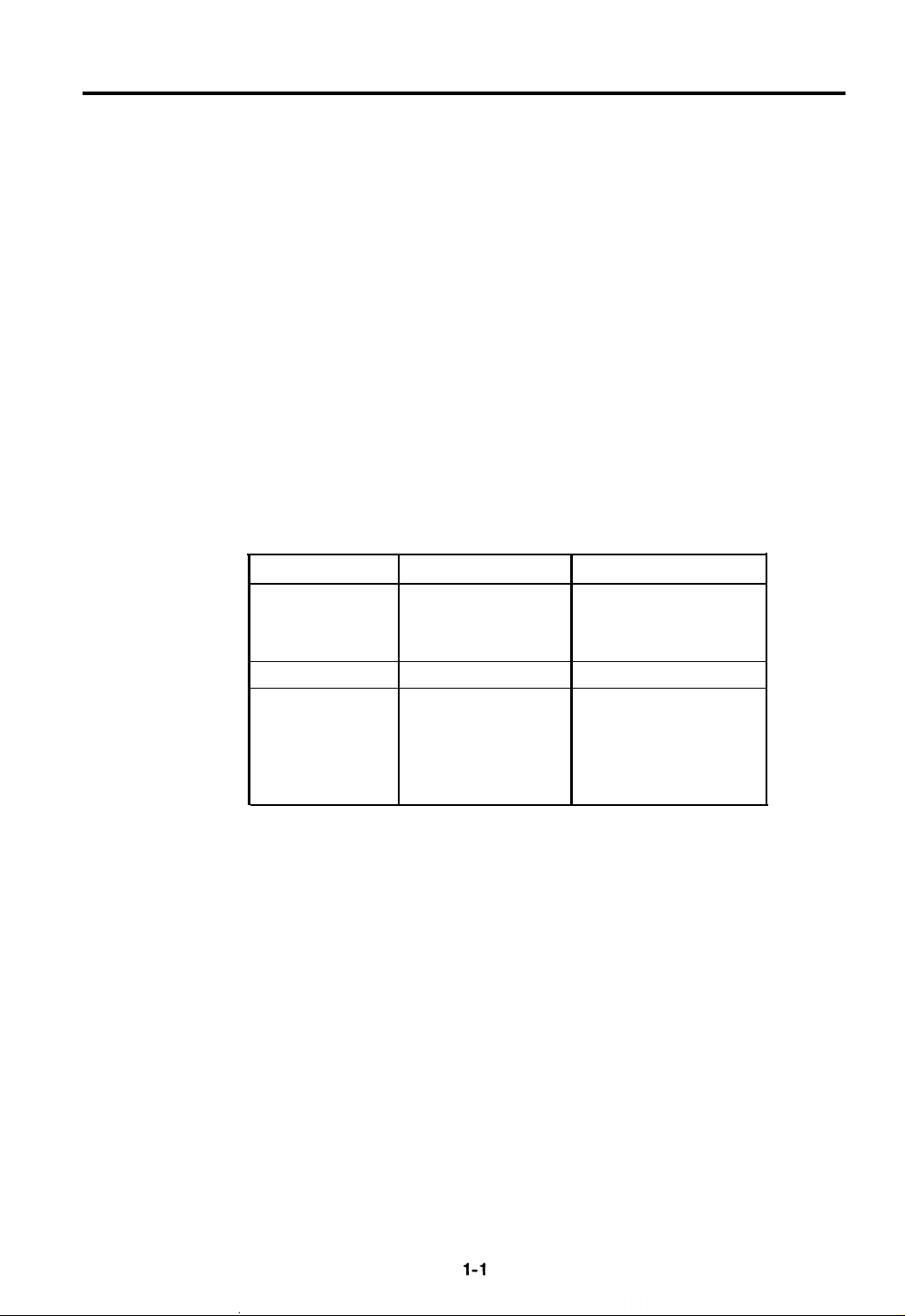
SPECIFICATIONS
16
April ’88
Configuration:
Copying Process:
Original:
Original Size:
Copy Paper Size:
Copy Paper Weight:
Reproduction Ratios:
Enlargement
Full Size
Reduction
Desk top
Dry electrostatic transfer system
Sheet/book
Maximum A3 (11“ x 17”)
Maximum A3 (11“ x 17”)
Minimum A6
(51/2" x
81/2”)
Cassette feed 52 to 128 g/m
Manual feed
52 to 157 g/m
See the following table:
v
A4 Version Letter Version
1:1.41 1:1.55
1:1.22
1:1.15
.
1:1
●
1:0 93
.
.
1:0.82
● . .
1:0.71
1:1.29
1:1.21
:G
11
.
1:0 93
●
.
1:0 77
1:0.74
1:0.65 1:0.65
2
(14 lb to 34 lb)
2
(14 lb to 42 lb)
Zoom:
From 65% to 155% in 1 % steps
Reproduction Ratio Full size - Enlargement or
Change:
Full size - Reduction in less than 5 seconds
Enlargement
- Reduction or
Reduction - Enlargement in less than 6.5
seconds
Page 5

16 April ’88
Copying Speed:
The copy speed (in copies per minute) is shown
in the following tables:
A4 Version
A3 B4 A4 B5
11
13
20 20
A4R B5R
15 15
Letter Version
LDG LG LT LT(R)
12 15
22
16
When used with document feeder, A4 (LT) speed
is 17 cpm (sideways).
First-Copy Time:
6.0 seconds (A4 or
81/2” x 11”)
Warm-Up Time: Approximately 100 seconds (23°C)
Copy Number Input:
Special Functions:
Numeral keys, 1 to 999, (count up or count down)
- Margin adjustment
- Auto size magnification mode
-2 single copies mode
- Auto paper select and auto reduce/eniarge
mode (with ADF only)
Manual Image Density
7 Steps (Development bias variable)
Selection:
Automatic Reset: 1 min. standard setting; can also be set to 3 min.
or no auto reset.
All functions canceled except cassette selection.
Quantity entered returns to “1”, and reproduction
ratio returns to full size.
1-2
Page 6

16 April ’88
Paper Feed:
- Double universal cassette feed, 250 sheets each
(auto cassette shift)
- Manual feed table
- Optional large capacity tray (LCT) at second
feed station.
Paper-Feed System: Friction-pad system
Exposure System: Slit exposure, moving optics
Lens:
Through lens, F8, f = 180mm
Light Source: Halogen lamp (85 V, 290 W)
Photoconductor:
Charge System:
Erase:
Selenium drum (F type)
Dual wire dc corona
LED lamp unit (34 LEDs)
Development System: Magnetic brush roller
Toner Density Control:
Development Bias
System:
Automatic, direct density sensing
Automatic voltage change (The control board
monitors the selected image density level, drum
temperature, and rest time.)
Toner Replenishment:
Toner Consumption:
Cleaning System:
Cartridge exchange (300 g/cartridge)
Approx. 7,500 copies/cartridge (A47% original)
Blade and brush
Quenching System: Photo-quenching
Image Transfer:
Paper Separation:
Single wire dc corona, pre-transfer lamp
Dual wire ac corona and pick-off pawls
Image Fusing:
Heat/pressure - roller type
Fusing Lamp: Halogen lamp (840 W)
1-3
Page 7

16 April ’88
Electronic Control
8-bit microprocessor
System:
Copy Tray Capacity:
250 sheets (B4 / 10” x 14”)
100 sheets (A3 / 11” x 17“)
Self-diagnostics:
19 codes, displayed in the copy counter
Power Source: 110V/60Hz....15A
115V/60Hz....15A
220V/50Hz....8A
220V/60Hz....8A
240V/50HZ....8A
Power Consumption: Warm-up:
1.0 kW
Stand-by: 0.08 kW
Copying: 0.42 kW (A4 sideways)
Dimensions:
Maximum:
Copier only:
1.22 kW
(WxDxH)
734 x 654 x 390 mm
28.9 x 25.8 x 15.4 inches
Full System:
1363 x 654 x 460 mm
53.7 x 25.7 x 14.1 inches
Weight:
65 kg (143 lb) (Copier only)
100 kg (221 lb) (Full System Without table)
Optional Equipment: Document Feeder
Sorter (20 bins)
Large Capacity Tray
Editor Board (requires editing eraser lamp)
Color Development Unit (Red, Blue, Green)
1-4
Page 8
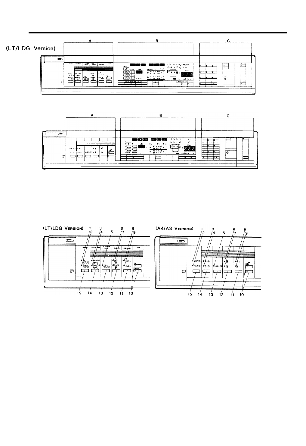
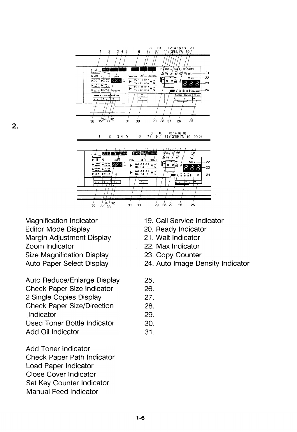
OPERATION PANEL
(A4/A3 Version)
16 April ’88
SECTION A
1. Sort Indicator
2. Stack Indicator
3. Auto Reduce/Enlarge Indicator
4. Auto Paper Select Indicator
5.2 Single Copies Indicator
6. Left Margin Adjustment Indicator
7. Right Margin Adjustment Indicator
8. Original Image Size Indicator
9. Copy Image Size Indicator
10. Zoom Keys
11. Size Magnification Key
12. Margin Adjustment Key
13.2 Single Copies Key
14. Auto Selection Key
15. Sorter Key
1-5
Page 9
16 April ’88
SECTION B
1. (LT/LDG Version)
(A4/A3 Version)
1,
2
3
4
5
6
7
8
9
10
11
12
13
14,
15.
16
17
18
4
<
●
.
,
.
●
Auto Image Density Key
Manual Image Density Key
Manual Image Density Indicator
Color Toner Indicator
Misfeed Location Display
Select Cassette Key
Paper Size Indicator
,
(
Full Size Key
32
Full Size Indicator
33
Magnification Ratio Indicator
34
Enlarge Key
35
Reduce Key
36
.
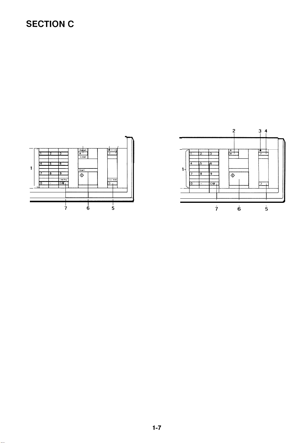
Page 10
16 April ’88
(LT/LDG Version)
-
1. Number Keys
2. Recall/Enter Key
3. Interrupt Indicator
4. Interrupt Key
(A4/A3 Version)
5. Clear Modes Key
6. Start Key
7. Clear/Stop Key
Page 11
Page 12

Page 13

16 April ’88
PAPER PATH
Paper feed starts from one of the two paper feed stations. The path followed
depends on which cassette the operator has selected. For copy processing,
all sheets follow the same path from the paper feed mechanism through the
fusing unit. After that, copies are delivered to the receiving tray.
1. Paper Feed
A friction pad and feed roller mechanism separates one sheet of paper from
the
paper stack and feeds it to the registration rollers. The registration rollers
are not turning at this time. The paper buckles slightly when the leading edge
reaches the registration rollers. Buckling seats the sheet securely between the
registration rollers and corrects skew.
1-10
Page 14

16 April ’88
2. Registration
At the programmed time, the registration rollers start turning to feed the paper
to the drum.
Image Transfer
3.
The toner image on the drum surface
is pulled from the drum onto the
passing paper by the transfer corona.
4. Paper Separation
The separation corona breaks the electrostatic attraction between the paper
and the drum. The suction of the vacuum fan pulls the paper onto the
transport belt. The transport belt moves the paper with the developed copy
image to the fusing unit.
5. Fusing
The paper passes between two rollers which bond the toner image to the
paper by applying heat and pressure. At this point the copy is complete.
1-11
Page 15
16 April ’88
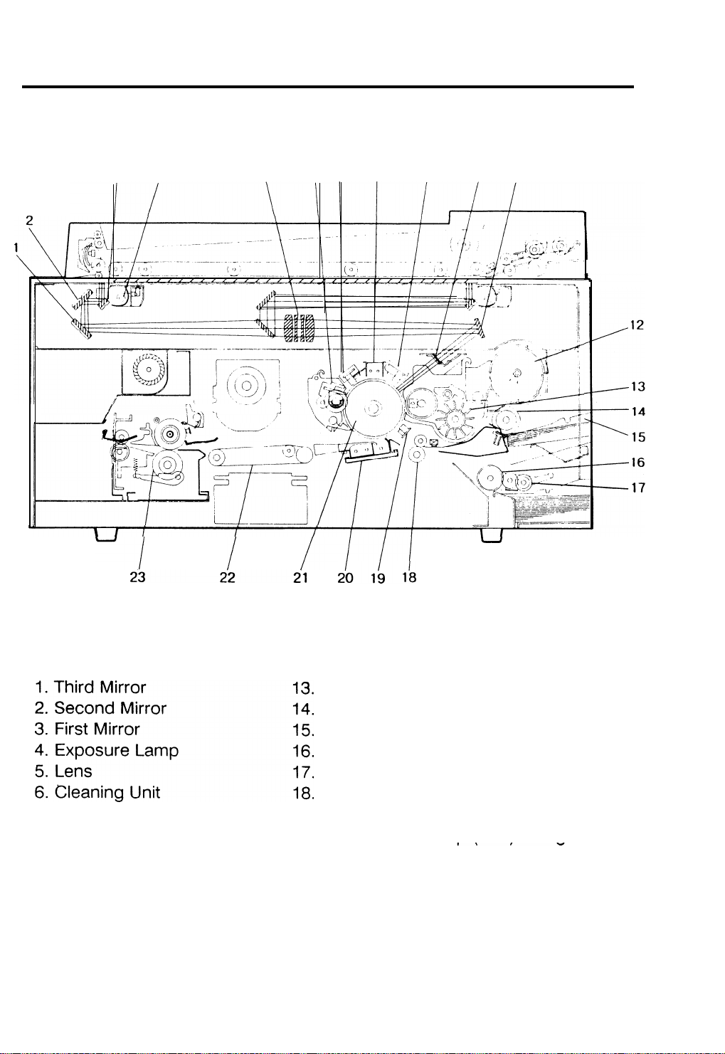
MECHANICAL COMPONENT LAYOUT
34
5
678 9
10 11
7
.
Quenching Lamp
Main Corona Unit
8
9
Erase Lamp Unit
10
Toner Shield Glass
(
11
Fourth Mirror
12
Toner Cartridge
Development Unit
First Feed Roller
First Cassette
Second Feed Roller
Pick-up Roller (LCT)
Registration Roller
19
.
Pre-Transfer Lamp (PTL) /lmaqe
Density Sensor Board
20. Transfer/Separation Corona Unit
21. Selenium Drum
22. Transport Belt
, 23. Fusing Unit
1-12
Page 16
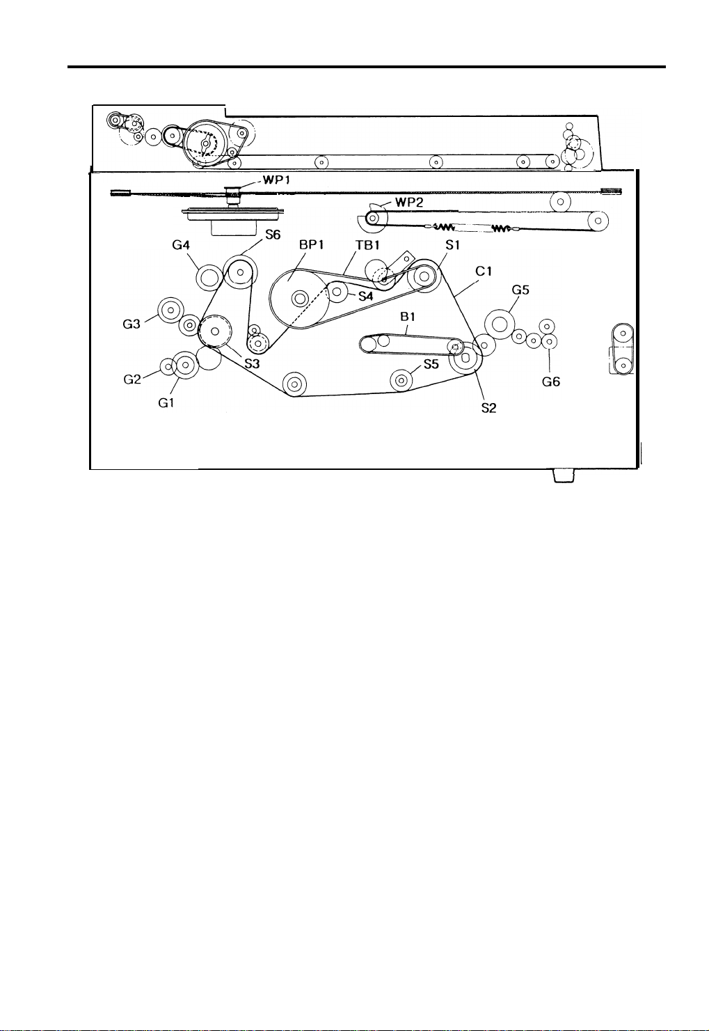
DRIVE LAYOUT
16 April ’88
Gears
G1
Second Feed Clutch Gear
Pick-up Roller Drive Gear(LCT)
G2
First Feed Clutch Gear
G3
G4
Toner Supply Clutch Gear
Hot Roller Drive Gear
G5
Exit Roller Drive Gear
G6
Sprockets
Main Motor Sprocket
S1
Fusing Drive Sprocket
S2
Feed Drive Sprocket
S3
S4
Cleaning Drive Sprocket
Toner Collection Bottle
S5
Drive Sprocket
S6
Development Drive Sprocket
Wire Pulleys
WP1 Scanner Drive Pulley
WP2 Second Scanner Drive Pulley
Timing Belt
TB1 Drum Drive Belt
Belt
B1 Transport Belt
Belt Pulley
BP1 Drum Drive Pulley
Chains
Cl Main Drive Chain
1-13
Page 17
16 April ’88
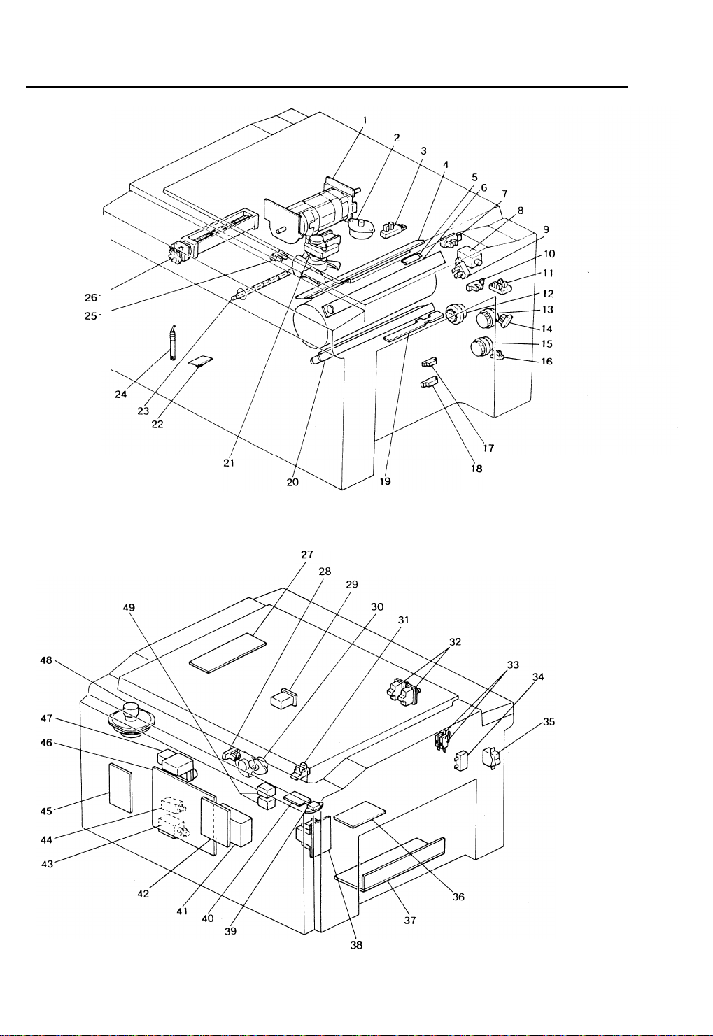
ELECTRICAL COMPONENT LAYOUT
.
1-14
Page 18

.
16 April ’88
1. Main Motor - Ml
2. Lens Drive Motor - M2
3. Lens HP Sensor - S1
4. Quenching Lamp - L1
5. Drum Heater
6. Erase Lamp - L2
7. Pulse Generator Sensor - S2
8. Toner Supply Solenoid - SOL1
9. Color Toner End Sensor - S3
10. Manual Feed Sensor - S4
11. Color Toner Sensors - S5
12. Registration MC - MCI
13. First Paper Feed MC - MC2
14. First Paper End Sensor - S6
15. Second Paper Feed MC - MC3
16. Second Paper End Sensor - S7
17. First Paper Size Sensor - S8
18. Second Paper Size Sensor - S9
19. Registration Sensor - S10
20. Pre Transfer Lamp - L3
27. Lamp Regulator PCB - PCB1
28. Second Scanner Home Position
Sensor - S12
29. Total Counter - CO1
30. Second Scanner Motor - M5
31. Scanner Home Position
Sensor - S13
32. Front Cover Safety Switch - SW2
33. Door Switch - SW1
34. Main Motor Capacitor - C
35. Main Switch - SW3
36. Relay PCB - PCB2
37. DC Power Supply Unit - PSU
38. Transformer - TR1
39. Fusing Triac - FT
40. Heater Control PCB - PCB5
41. Power Pack - T/S - P1
42. Interface Board - PCB3
43. Cleaning Solenoid - SOL2
44. Pick-off Solenoid - SOL3
21. Vacuum Fan Motor - M3
22. Toner Overflow Sensor - S14
23. Fusing Lamp - L4
24. Oil End Sensor - S15
25. Paper Exit Sensor - S11
26. Exhaust Blower Motor - M4
45. Feed Control PCB - PCB4
46. Main PCB - PCB6
47. Power Pack - C/B - P2
48. Scanner Drive Motor - M6
49. AC Drive Relay - R1
1-15
Page 19

16 April ’88
ELECTRICAL COMPONENT DESCRIPTIONS
SYMBOL
NAME
Motors
Ml
M2
M3
M4
M5
M6
Main Motor
Lens Drive Motor
Vacuum Fan Motor
Exhaust Blower
Motor
Second Scanner
Motor
Scanner Drive Motor
Magnetic Clutches
MC1
MC2
MC3
Registration MC
First Paper Feed MC
Second Paper Feed
MC
FUNCTION
Drives all main unit components
except otics unit and fans/bIowers.
(100Vac)
Positions the lens. (dc stepper)
Provides suction so that paper is
held firmly on the transport belt. (100
Vat)
Removes heat from around the
fusing unit. (100 Vat)
Positions the second scanner. (dc
stepper)
Drives the scanner. (dc stepper)
Drives the registration rollers.
Starts paper feed from the first paper
feed station.
Starts Paper feed from the second
fe1’
paper eed station.
LOCATION
1
2
21
26
30
48
12
13
15
Solenoids
SOL1
SOL2
SOL3
Switches
SW1
SW2
SW3
Sensors
S1
S2
Toner Supply
Solenoid
Cleaning Solenoid
Pick-off Solenoid
Door Switch
Front Cover Safety
Switch
Main Switch
Lens Home Position
Sensor
Pulse Generator
Energizes to supply toner.
Moves the cleaning blade against the
drum.
Brings the pick-off pawls into contact
with the drum.
Enables the Door Open indicator.
Cuts ac power to ac components.
Supplies power to the copier.
Informs the CPU when the lens is at
the full size position.
Supplies timing pulses to the main
board.
8
43
44
33
32
35
3
7
1-16
Page 20

16 April ’88
SYMBOL
S3
S4
S5
S6
S7
S8
S9
S10
S11
S12
NAME
Color Toner End
Sensor
Manual Feed Sensor
Color Toner Sensors
First Paper End
Sensor
Second Paper End
Sensor
First Paper Size
Sensor
Second Paper Size
Sensor
Registration Sensor
Paper Exit Sensor
Second Scanner
Home Position
Sensor
FUNCTION
Detects when it is time to add toner.
Detects when the manual feed table
is open.
Detects which color toner
development unit is installed.
Informs the CPU when the first
cassette runs out of paper.
Informs the CPU when the second
cassette runs out of paper.
Determines what size paper is in the
first cassette.
Determines what size paper is in the
second cassette.
Misfeed detector and ON/OFF timing.
Misfeed detector.
Informs the CPU when the second
scanner is at the home position.
LOCATION
9
10
11
14
16
17
18
19
25
28
S13
S14
S15
Scanner Home
Position Sensor
Toner Overflow
Sensor
Oil End Sensor
Printed Circuit Boards
PCB1
PCB2 Relay PCB
PCB3 Interface PCB
PCB4
PCB5
PCB6
Lamp Regulator PCB
Feed Control PCB
Heater Control PCB
Main PCB
Lamps
L1
L2
L3
Quenching Lamp
Erase Lamp
Pre-Transfer Lamp
Informs the CPU when the scanner is
at the home position.
Detects when the
full
.
Detects low
Regulates the exposure lamp voltage.
Main power relay. Provides 100 volts
ac to motors and circuits.
Interfaces the data
copier main board and the sorter
and/or DF main boards.
Contains multiplexing circuitry to
control feed components.
Controls heater switching.
Controls all copier functions both
directly and through other PCBS.
Neutralizes any charge remaining on
the drum surface after cleaning.
Discharges the drum outside of the
image area. Provides lead/traiI edge
erase and editing functions.
Reduces charge on the drum surface
before transfer.
used toner bottle is
oil condition.
between the
31
22
24
27
36
42
45
40
46
4
6
20
1-17
Page 21

16 April ’88
SYMBOL
L4
Power Packs
P1
P2
Transformer
TR1
Counter
CO1
Relays
R1
NAME
Fusing Lamp
Power Pack - T/S
Power Pack - C/B
Transformer
Total Counter
AC Drive Relay
FUNCTION
Provides heat to the fusing unit.
Provides dc voltage for the transfer
and provides ac and dc voltage for
separation coronas.
Provides high voltage power for the
charge corona and the development
roller bias.
Steps down the wall voltage to 100
Vat.
Keeps track of the total number of
copies made.
Main Power Relay
LOCATION
23
41
47
38
29
49
Others
c
FT
PSU
Main Motor Capacitor
Fusing Triac
DC Power Supply
Unit
Start capacitor
Switches fusing lamp on and off.
Rectifies 100 Vac input and outputs
dc voltages.
34
39
37
1-18
Page 22
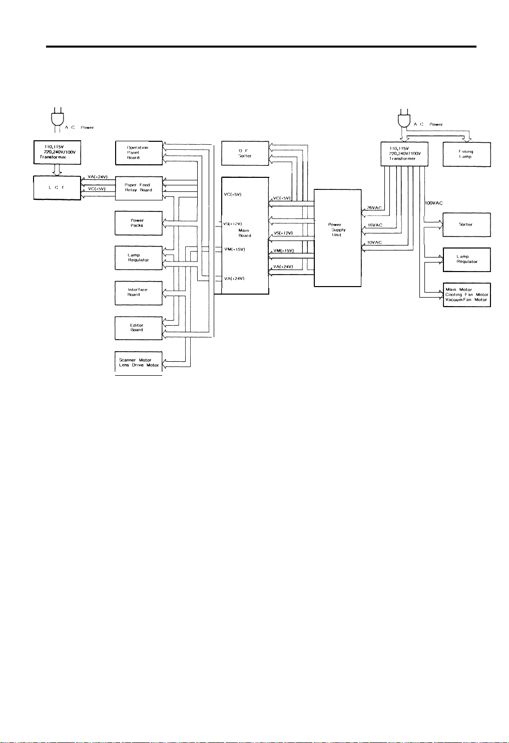
AC AND DC POWER DISTRIBUTION
16 April ’88
The ac power supply is filtered then distributed to the fusing lamp and the
main transformer. The transformer supplies 100 volts to the cooling fan,
vacuum fan, and the main motor.
The”dc power supply unit receives ac 26, 16, and 10 volts, via fuses, from the
main transformer. These voltages are rectified and regulated to 24, 15 and 12,
and 5 volts respectively and distributed to the sorter, ADF, and the copier
main board. All supplies have their own ground line.
The main board supplies voltage to all copier electrical components including:
power packs, PCBs, and relays. It also supplies the editor.
The LCT has a separate power supply.
1-19
Page 23
16 April ’88
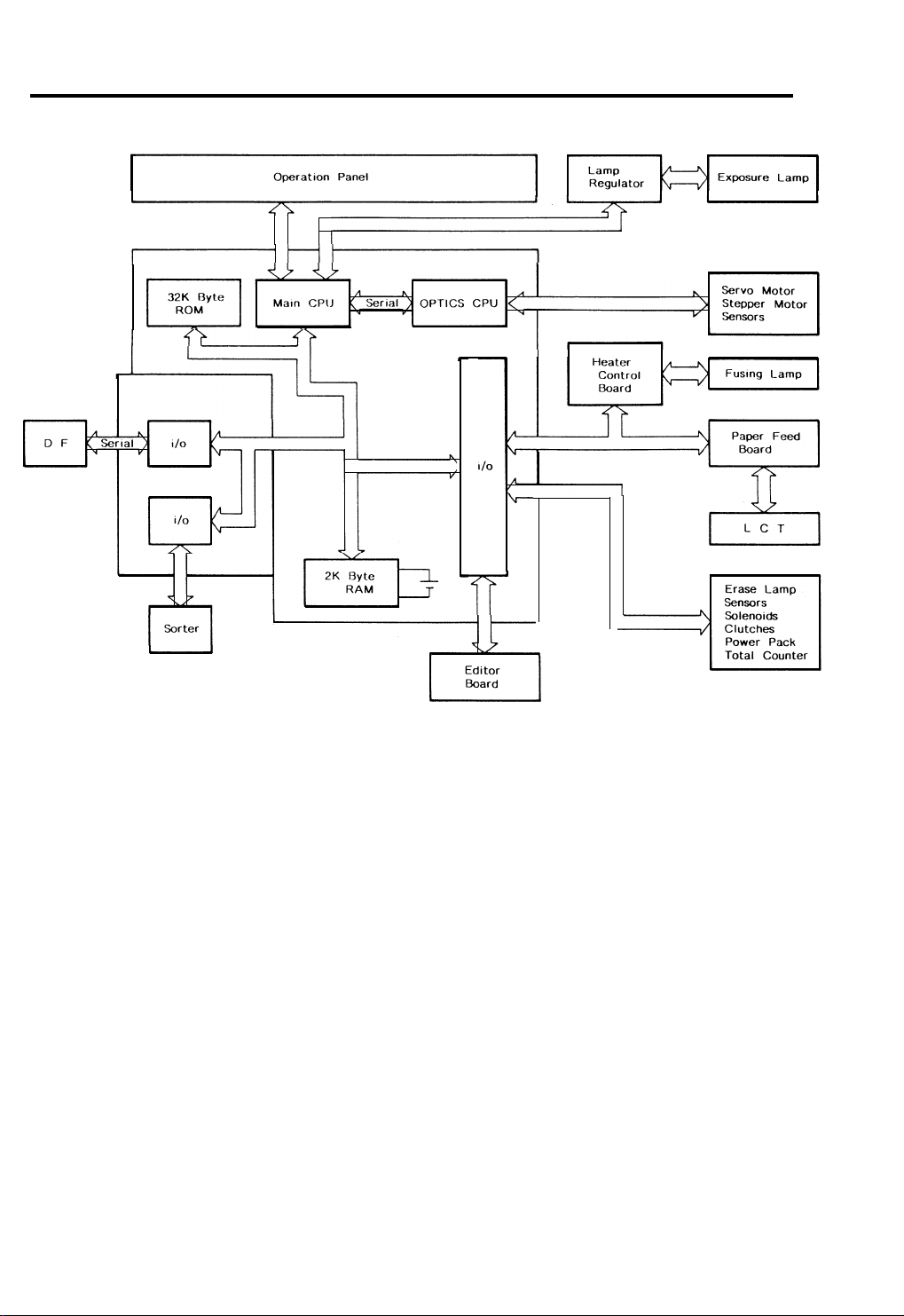
OVERALL MACHINE CONTROL
The base copier has two CPUs on the main board that control all machine
operations (the main CPU and the optics CPU).
The main CPU is the main controller of this copier. It monitors the input
signals from sensors and controls the electrical devices through program
mable 1/0 devices. The main board has a RAM (2 kilobytes) for the service
program function. A battery backs up the power to this RAM. This CPU con
trols the fusing lamp, via the heater control board, the exposure lamp, via the
lamp regulator, and motors directly from the main board.
The optics CPU controls the servomotor (15 volts) and the stepper motors
(24 volts) for the optics section.
The interface board is connected to the copier main board when the
document feeder and/or sorter are installed.
1-20
Page 24
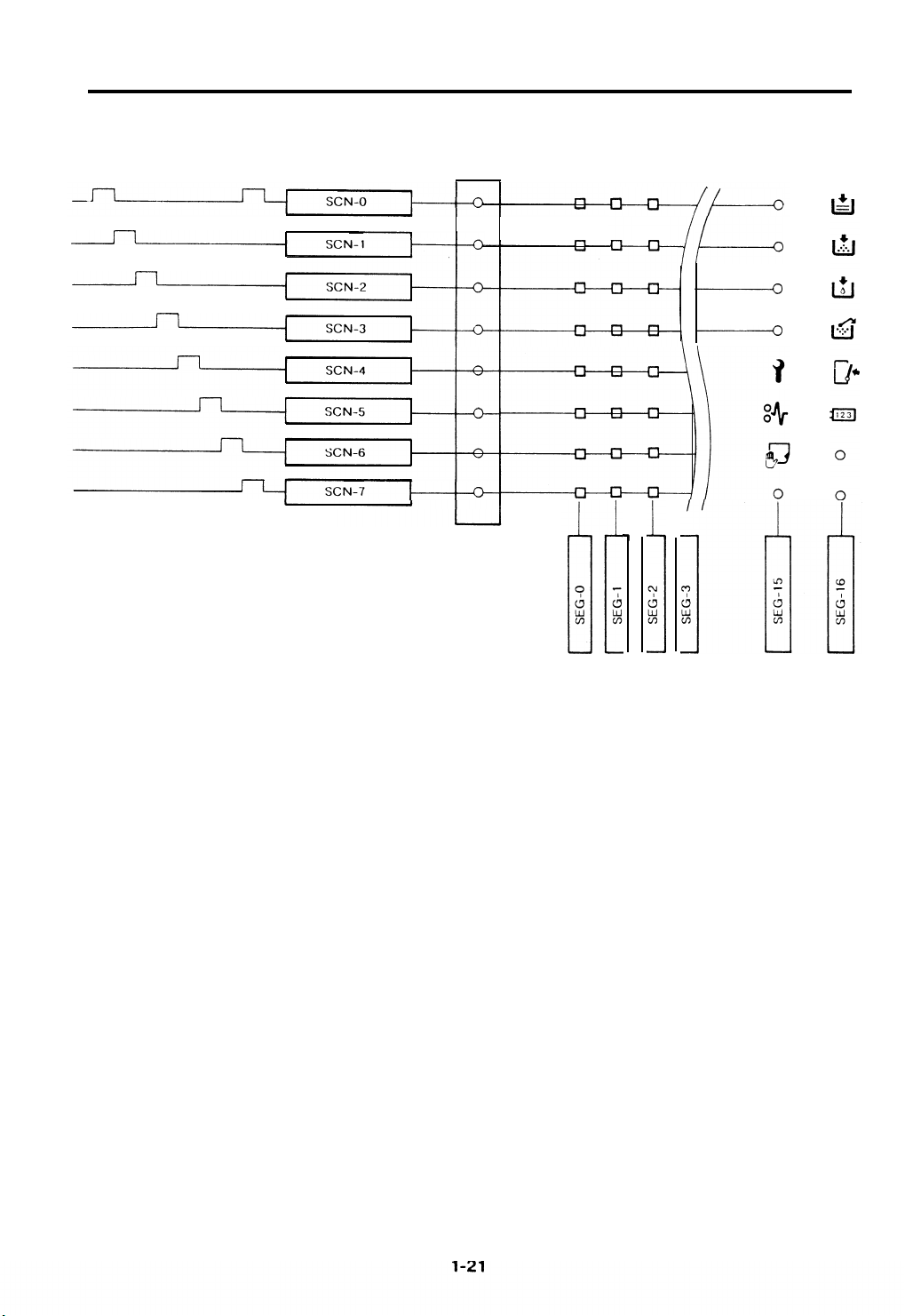
OPERATION PANEL CONTROL
16 April ’88
The CPU controls all functions of the operation panel. The CPU sends data to
programmable 1/0 devices which form a multiplexing circuit consisting of 8
scan lines and 17 segment lines, Transistors drive all the scan lines at 12 volts
to reduce effects from noise.
The multiplexing circuit lights all displays and monitors all keys of the
operation panel. The door switch is also monitored by this circuit and acts like
any other operation panel key. The counters are also controlled by the
operation panel multiplexing circuit and act like the operation panel lamps.
Page 25

SECTION 2
DETAILED SECTION
DESCRIPTIONS
Page 26

OVERVIEW . . . . . . . . . . . . . . . . . . . . . . . . . . . . . . . . . . . . . . . . . . . . . . . . . : . . . . . . ...2-6
LEAD EDGE ERASE . . . . . . . . . . . . . . . . . . . . . . . . . . . . . . . . . . . . . . . . . . . . . . . . . ...2-7
SIDE ERASE . . . . . . . . . . . . . . . . . . . . . . . . . . . . . . . . . . . . . . . . . . . . . . . . . . . . . . . ...2-7
I. Side Erase Operation . . . . . . . . . . . . . . . . . . . . . . . . . . . . . . . . . . . . . . . . . . ...2-8
TRAIL EDGE ERASE . . . . . . . . . . . . . . . . . . . . . . . . . . . . . . . . . . . . . . . . . . . . . . . . . ...2-9
ERASE LAMP CIRCUIT . . . . . . . . . . . . . . . . . . . . . . . . . . . . . . . . . . . . . . . . . . . . . . ...2-10
OPTICS . . . . . . . . . . . . . . . . . . . . . . . . . . . . . . .. . . . . . . . . . . . . . ...2-12
OVERVIEW . . . . . . . . . . . . . . . . . . . . . . . . . . . . . . . . . . . . . . . . . . . . . . . . . . . . . . . ...2-12
SCANNER DRIVE . . . . . . . . . . . . . . . . . . . . . . . . . . . . . . . . . . . . . . . . . . . . . . . . . . ...2-13
I. Scanner Drive Mechanism . . . . . . . . . . . . . . . . . . . . . . . . . . . . . . . . . . . . . . ...2-13
2. Scanner Motor Control
LENS/MIRRORPOSITIONING
I. Lens Drive . . . . . . . . . . .
Z. Lens Positioning . . . . . .
3. Second Scanner Drive .
4. Second Scanner Positioning . . . . . . . . . . . . . . . . . . . . . . . . . . . . . . . . . . . . ...2-18
STEPPER MOTOR CONTROL . . . . . . . . . . . . . . . . . . . . . . . . . . . . . . . . . . . . . . . . ...2-19
AUTOMATIC IMAGE DENSITY SENSING . . . . . . . . . . . . . . . . . . . . . . . . . . . . . . . ...2-20
EXPOSURE LAMP CONTROL . . . . . . . . . . . . . . . . . . . . . . . . . . . . . . . . . . . . . . . . ...2-21
Service Call Conditi.ons . . . . . . . . . . . . . . . . . . . . . . . . . . . . . . . . . . . . . . . . . . . . . . ...2-22
DEVELOPMENT . . . . . . . . . . . . . . . . . . . . . . . . . . . . . . . . . . . . . . ...2-23
overview . . . . . . . . . . . . . . . . . . . . . . . . . . . . . . . . . . . . . . . . . . . . .
DRIVE MECHANISM . . . . . . . . . . . . . . . . . . . . . . . . . . . . . . . . . . . . . . . . . . . . . . . . ...2-24
SEALS AND END MAGNETS . . . . . . . . . . . . . . . . . . . . . . . . . . . . . . . . . . . . . . . . . ...2-25
CROSS-MIXING . . . . . . . . . . . . . . . . . . . . . . . . . . . . . . . . . . . . . . . . . . . . . . . . . . . ...2-26
IMAGE DENSITY CONTROL . . . . . . . . . . . . . . . . . . . . . . . . . . . . . . . . . . . . . . . . . ...2-27
1. ManualImag eDensityControl . . . . . . . . . . . . . . . . . . . . . . . . . . . . . . . . . . . ...2-27
Z. Automatic Image Density Control . . . . . . . . . . . . . . . . . . . . . . . . . . . . . . . . ...2-28
. . . . . . . . . . . . ...2-23
3. Bias Compensation Factors . . . . . . . . . . . . . . . . . . . . . . . . . . . . . . . . . . . . . ...2-29
4. Rest Time Compensation (V2) . . . . . . . . . . . . . . . . . . . . . . . . . . . . . . . . . . . ...2-29
5. Drum Temperature Compensation (V3) . . . . . . . . . . . . . . . . . . . . . . . . . . . . . .2-30
6. Total Bias (VT) . . . . . . . . . . . . . . . . . . . . . . . . . . . . . . . . . . . . . . . . . . . . . . . . ...2-30
BIAS FOR ID SENSING . . . . . . . . . . o . . . . . . . . . . . . . . . . . . . . . . . . . . . . . . . . . . . ...2-31
BIAS CONTROL CIRCUIT . . . . . . . . . . . . . . . . . . . . . . . . . . . . . . . . . . . . . . . . . . . . ...2-32
Page 27

COLOR DEVELOPMENT . . . . . . . . . . . . . . . . . . . . . . . . . . . . . . . . . . . . . . . . . . . . . . .2-33
I. Overview . . . . . . . . . . . . . . . . . . . . . . . . . . . . . . . . . . . . . . . . . . . . . . . . . . . . ...2-33
Z. Bias Control . . . . . . . . . . . . . . . . . . . . . . . . . . . . . . . . . . . . . . . . . . . . . . . . . ...2-33
3. Base Bias for Color . . . . . . . . . . . . . . . . . . . . . . . . . . . . . . . . . . . . . . . . . . . . ...2-33
4. Bias for lD Sensing . . . . . . . . . . . . . . . . . . . . . . . . . . . . . . . . . . . . . . . . . . . . ...2-33
5. Color Detection . . . . . . . . . . . . . . . . . . . . . . . . . . . . . . . . . . . . . . . . . . . . . . . ...2-34
SERVICE CALL CONDITION . . . . . . . . . . . . . . . . . . . . . . . . . . . . . . . . . . . . . . . . . ...2-35
TONER DENSITY DETECTION AND TONER SUPPLY . . . . . . . . ...2-36
TONER DENSITY DETECTION . . . . . . . . . . . . . . . . . . . . . . . . . . . . . . . . . . . . . . . ...2-36
TONER DENSITY CONTROL . . . . . . . . . . . . . . . . . . . . . . . . . . . . . . . . . . . . . . . . . ...2-37
TONER SUPPLY . . . . . . . . . . . . . . . . . . . . . . . . . . . . . . . . . . . . . . . . . . . . . . . . . . . ...2-39
I. Roller Drive Mechanism.. . . . . . . . . . . . . . . . . . . . . . . . . . , . . . . . . . . . . . . ...2-39
Z. Toner Agitator Drive Mechanism . . . . . . . . . . . . . . . . . . . . . . . . . . . . . . . . . ...2-40
TONER SUPPLY AMOUNT . . . . . . . . . . . . . . . . . . . . . . . . . . . . . . . . . . . . . . . . . . . ...2-41
l. Detect Supply Mode . . . . . . . . . . . . . . . . . . . . . . . . . . . . . . . . . . . . . . . . . . . ...2-41
Z. Fixed Supply Mode . . . . . . . . . . . . . . . . . . . . . . . . . . . . . . . . . . . . . . . . . . . . ...2-41
TONER END DETECTION . . . . . . . . . . . . . . . . . . . . . . . . . . . . . . . . . . . . . . . . . . . ...2-42
COLORTONERDENSITY DETECTIONANDCOLOR TONER SUPPLY . . . . . . . ...2-42
l. Color Toner Density Control . . . . . . . . . . . . . . . . . . . . . . . . . . . . . . . . . . . . ...2-42
Z. Color Toner End Detection. . . . . . . . . . . . . . . . . . . . . . . . . . . . . . . . . . . . . . ...2-43
3. Abnormal Condition . . . . . . . . . . . . . . . . . . . . . . . . . . . . . . . . . . . . . . . . . . . ...2-44
SERVICE CALL CONDITION . . . . . . . . . . . . . . . . . . . . . . . . . . . . . . . . . . . . . . . . . ...2-44
IMAGE TRANSFER AND PAPER SEPARATION . . . . . . . . . . . . . ...2-45
PRE-TRANSFER LAMP (PAL).... . . . . . . . . . . . . . . . . . . . . . . . . . . . . . . . . . . . . . ...2-45
IMAGE TRANSFER . . . . . . . . . . . . . . . . . . . . . . . . . . . . . . . . . . . . . . . . . . . . . . . . . ...2-45
PAPER SEPARATION . . . . . . . . . . . . . . . . . . . . . . . . . . . . . . . . . . . . . . . . . , . . . . . ...2-46
PRE-TRANSFER LAMP CIRCUIT. . . . . . . . . . . . . . . . . . . . . . . . . . . . . . . . . . . . . . ...2-47
TRANSFER/SEPARATIONCORONA CIRCUIT . . . . . . . . . . . . . . . . . . . . . . . . . . . ...2-48
PICK-OFF MECHANISM . . . . . . . . . . . . . . . . . . . . . . . . . . . . . . . . . . . . . . . . . . . . . ...2-49
l. Touch and Release Mechanism . . . . . . . . . . . . . . . . . . . . . . . . . . . . . . . . . . ...2-49
2. Side to Side Movement . . . . . . . . . . . . . . . . . . . . . . . . . . . . . . . . . . . . . . . . ...2-50
PICK-OFF CIRCUIT . . . . . . . . . . . . . . . . . . . . . . . . . . . . . . . . . . . . . . . . . . . . . . . . . ...2-51
DRUM CLEANING . . . . . . . . . . . . . . . . . . . . . . . . . . . . . . . . . . . . . ...2-52
OVERVIEW . . . . . . . . . . . . . . . . . . . . . . . . . . . . . . . . . . . . . . . . . . . . . . . . . . . . . . . ...2-52
Page 28

.
16 April ’88
DRUM
SELENIUM DRUM
Selenium has the characteristics of:
1
.
Being able to accept a high positive electrical charge in the dark. (The
electrical resistance of selenium is high in the absence of light.)
2
.
Dissipating the electrical charge when exposed to light. (The conductivity
of selenium is greatly enhanced by exposure to light.)
.
Dissipating an amount of charge in direct proportion to the intensity of the
3
light. That is, where a stronger light illuminates the selenium surface, a
smaller voltage remains on the selenium.
The sensitivity of selenium changes slightly with variations in the surface
temperature of the drum. (Under cool conditions, the drum may be
excessively charged; this will result in background or excessive image
density.) To prevent this, the CPU monitors the temperature variations around
the drum and changes the development bias accordingly. Also, during cold
periods, the drum heater warms the drum.
Drum sensitivity also depends on how long the drum has rested between
copy runs. The copier’s CPU compensates for changes in drum sensitivity
due to rest time by changing the development bias. This prevents variations in
image density at the beginning of copy runs
The selenium drum used in this model has high sensitivity, good color
reproduction,
and good reproduction of low contrast originals (pencil
originals, etc.)
2-1
Page 29

16 April ’88
HANDLING THE DRUM
1
.
Never touch the drum surface with bare hands.
2
●
Store the drum in a CooI dry place away from heat.
.
When cleaning the drum, always wear gloves.
3
4
.
Prime the drum with setting powder only when installing a new drum.
●
Never expose the drum to light for long periods.
5
.
Drum conditioning is necessary after installing a new drum. In addition, it
6
should be done at the following times:
1 ) When image density is reduced due to over exposure of the drum
2) After cleaning the drum
3) When the drum is lightly scratched.
7
●
Always keep the drum in the protective sleeve when inserting or pulling
the drum out of the copier.
.
Before inserting or pulling out the drum, pull the cleaning unit out slightly
8
to avoid scratching the drum on the pick-off pawls.
.
Return used drums to the distributor according to standard procedure.
9
Page 30
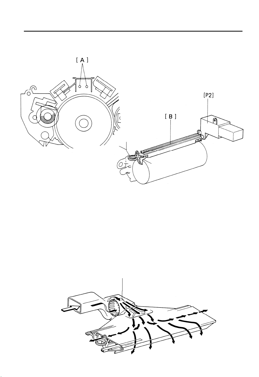
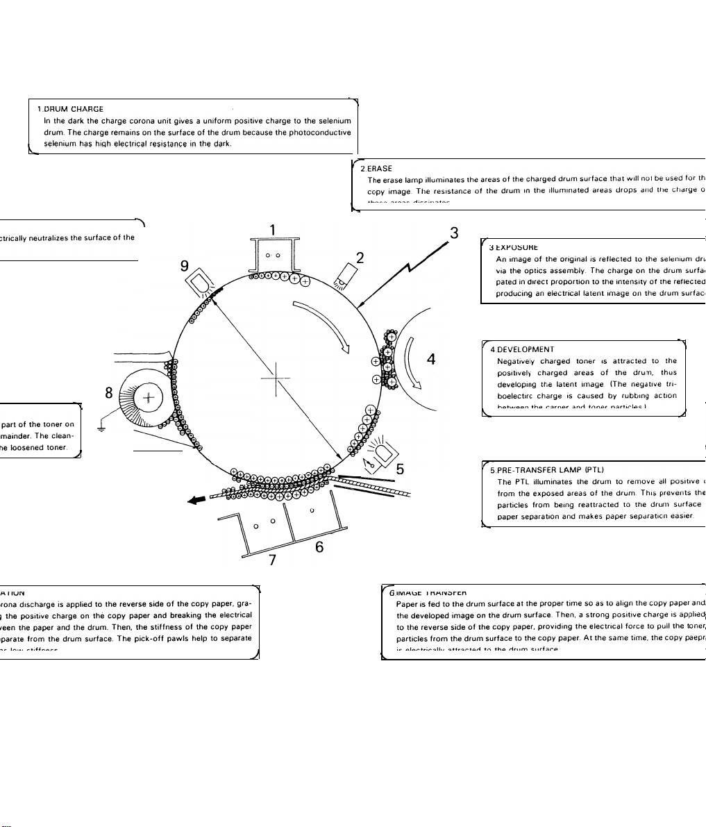
DRUM CHARGE
OVERVIEW
16 April ’88
This copier uses
drum. The corona wires generate a corona of positive ions when the charge
power pack [P2] applies a high positive voltage. The selenium coating
receives a uniform positive charge (750 t 50 volts) as it rotates
corona unit [B].
The main motor fan [C] provides a smooth flow of air to the interior of
charge corona unit to prevent uneven build-up of positive ions. (An uneven
build up of positive ions could cause uneven image density.)
a dual wire corotron [A] and a highly sensitive selenium
past
the
the
[cl
2-3
Page 31

16 April ’88
CORONA WIRE CLEANER
The flow of air around the charge corona wires [A] may deposit paper dust or
toner particles on the corona wires.
These particles may interfere with
charging and cause low density bands on copies. The wire cleaner [B] allows
the operator to correct this problem by simply pulling out and pushing in the
corona unit.
Each corona wire is held between two pads on the wire cleaner bracket [C].
The wires ride between the pads when the unit is pulled out, and the pads
clean off any particles on the wires.
2-4
Page 32

CHARGE CORONA POWER PACK
16April ’88
The circuit operation for the charge corona [A] begins with the input of +24
volts to the power pack at CN1-1. This power supply is used for the high
voltage coronas.
The charge corona turns on 0.42 second after the Start key is pressed. A
LOW
signal from the main board (at CN206-A22) energizes the power pack.
The charge corona always turns on at the same time, but the off timing
depends on paper size.
2-5
Page 33

16 April ’88
ERASE
OVERVIEW
Lead Edge Erase Margin
Side Margins -size copies, the total of both side
margins is less than
Original Image width
Charged width on the Drum
Lead Edge Erase
Side Erase
The erase lamp [A] consists of a line of LEDs extending across the full width
of the drum [B].
The erase lamp has three functions: lead edge erase, side erase, and trail
edge erase. Trail edge erase begins after the trailing edge of the copy paper;
therefore, the trailing edge of the copy will not be erased.
4 mm. )
The erase lamp unit [A] also has two thermistors: TH-I and TH-2. Both of
these thermistors detect the temperature around the drum. TH-1 selects the
proper rest time compensation, and TH-2 controls the development bias
voltage.
Page 34

LEAD EDGE ERASE
The entire line of LEDs turns on when the main motor turns on. They stay on
until the erase margin slightly overlaps the lead edge of original image area on
the drum (Lead Edge Erase Margin). This prevents the toner density sensor
pattern from being developed on every copy cycle and prevents the edge of
the original from appearing on the copy image. The width of the lead edge
erase margin can be adjusted using SP Mode # 41.
During image density detection cycles (once every ten cycles), the center
block of erase lamps turns off long enough for the sensor pattern to be
developed.
SIDE ERASE
Based on the paper size and on the reproduction ratio, the LEDs turn on in
pairs (one on either side) to discharge the drum potential on both sides. This
reduces toner consumption and drum cleaning load.
The CPU adjusts the side erase margin to be as near as possible to the actual
image size, even when using the zoom function. However, since the erase
lamp LEDs will not work in precise one millimeter intervals, the side erase
margin varies slightly depending on the reproduction ratio. The width of the
side erase margin varies from O mm to a maximum of 6 mm (total of both
sides).
2-7
Page 35

16 April ’88
1. Side Erase Operation
The tables below show which erase lamps turn off,
size and reproduction ratio selected. Note that A3 side edge erase occurs
because the charge corona end block covers stop the edges of the drum
from receiving charge.
2-8
Page 36

16 April ’88
TRAIL EDGE ERASE
Normally, the erase lamps turn on after the trailing edge of the latent image
has passed. Therefore, a trail edge erase margin cannot be observed on the
copy. Trail edge erase ON timing is the same as charge corona OFF timing.
During enlargement or reduction, the trail erase ON timing changes according
to the paper size and the reproduction ratio.
Page 37

16 April ’88
ERASE LAMP CIRCUIT
This copier uses 34 LEDs in the erase lamp unit.
Shift register drivers control the LEDs. Initially, the RESET signal (LOW active)
turns off all the shift registers. Then the main board sends erase lamp data to
the shift registers from CN203-15.
2-1o
Page 38

16 April ’88
After the RESET signal goes back to HIGH, the shift registers start accepting
data. If the data line is HIGH at the time of the CLOCK pulse (rising edge), the
shift register is set to turn the LED on; if it is LOW, the the shift register is set
to keep the LED off. The data in the shift registers is shifted right one position
at the start of each clock cycle; so, it takes 34 CLOCK pulses to set the shift
registers for all the LEDs.
After all data bits have been sent, the main board sends the LATCH signal to
turn on the erase lamp unit. The latch signal sets the shift registers which turn
on all LEDs for which data bits have been set.
The center section of LEDs turns on and off as a block, and the outer LEDs
turn on and off in pairs.
2-11
Page 39

16
April ’88
OPTICS
During the copy cycle, an image
surface
Light Path:
Exposure Lamp [A] --> Original [B] --> First Mirror [C] -->
Second Mirror [D] --> Third Mirror [E] -->
Fourth Mirror [G] --> Toner Shield Glass [H] --> Drum [1]
The cooling blower [J] circulates cool air into the optics cavity. The air flows
from the right to the left in the optics cavity and exhausts through the vents in
the top cover. This blower operates during every copy cycle.
This model has eight standard reproduction ratios: four reduction ratios, three
enlargement ratios, and full size. In addition, it has a zoom function. The user
can change the reproduction ratio in one percent steps from 65% to 155%.
Stepper motors are used to change the positions of the lens and mirrors.
Separate motors are used because of the wide range of reproduction ratios.
The scanner drive motor is a servomotor and is controlled by the optics CPU.
The scanner drive motor changes the scanner speed depending on the
reproduction ratio.
via the optics assembly as
of the original
follows.
Lens [F] -->
.
This copier has a special function: the 2 Single Copies mode, which makes
two single copies from a bound document.
2-12
Page 40

SCANNER DRIVE
16 April ’88
1. Scanner Drive Mechanism
This model uses a dc servomotor [A] to drive the scanners.
The first scanner [B], which consists of the exposure lamp [C] and the first
mirror, is connected to the scanner drive wire by the wire clamp [D]. The
second scanner [E], which consists of the second and third mirrors, is
connected to the scanner drive wire by a movable pulley (the second scanner
pulley
[F]).
The pulley moves the second scanner at half the velocity of the first scanner.
This is to maintain the focal distance between the original and the lens during
scanning. This relationship can be expressed as:
V1r = 2(V2r)
where: r =
Reproduction ratio
= VD/r
V1r = First scanner velocity (when the reproduction ratio is “r”)
V2r =
VD
—
—
Second scanner velocity (when the reproduction ratio is “r”)
Drum peripheral velocity (150 mm/s)
The wire clamp for the first scanner also works as the actuator of the home
position sensor. The CPU controls both the registration and return timing.
2-13
Page 41

SCANNER DRIVE
16 April ’88
1. Scanner Drive Mechanism
This model uses a dc servomotor [A] to drive the scanners.
The first scanner [B], which consists of the exposure lamp [C] and the first
mirror, is connected to the scanner drive wire by the wire clamp [D]. The
second scanner [E], which consists of the second and third mirrors, is
connected to the scanner drive wire by a movable pulley (the second scanner
pulley
[F]).
The pulley moves the second scanner at half the velocity of the first scanner.
This is to maintain the focal distance between the original and the lens during
scanning. This relationship can be expressed as:
V1r = 2(V2r)
where: r =
Reproduction ratio
= VD/r
V1r = First scanner velocity (when the reproduction ratio is “r”)
V2r =
VD
—
—
Second scanner velocity (when the reproduction ratio is “r”)
Drum peripheral velocity (150 mm/s)
The wire clamp for the first scanner also works as the actuator of the home
position sensor. The CPU controls both the registration and return timing.
2-13
Page 42

16 April ’88
2. Scanner Motor Control
The scanner drive motor [M6] is a servomotor, The optics CPU on the main
board [PCB6] controls the speed of this servomotor. The main CPU and the
optics CPU communicate through a serial interface bus.
At the programmed time, the main CPU sends a scanner start signal to the
optics CPU. The optics CPU then checks the drum speed by monitoring the
pulses from the pulse generator.
Based on this input, the optics CPU
determines the proper speed for the scanner drive motor. The optics CPU
sends the speed data to the timer IC which sends the motor drive pulses.
The. encoder on the servomotor has a photointerrupter that generates pulse
signals. The optics CPU monitors the scanner speed by these pulse signals
and uses this data to regulate the servomotor speed.
The home position sensor [S13] informs the optics CPU whether the first
scanner is in the home position.
2-14
Page 43

LENS/MIRROR POSITIONING
[B]
16 April ’88
[M2]
[A]
1. Lens Drive
The lens drive motor [M2] (stepper motor) changes the lens [A] position in
accordance with the selected reproduction ratio to provide the proper optical
distance between the lens and the drum surface.
The lens drive motor drives the entire lens unit through an idle gear [B]. The
rotation of the lens drive pulley moves the lens back and forth in discrete
steps.
2-15
Page 44

16 April ’88
2. Scanner Motor Control
The scanner drive motor [M6] is a servomotor, The optics CPU on the main
board [PCB6] controls the speed of this servomotor. The main CPU and the
optics CPU communicate through a serial interface bus.
At the programmed time, the main CPU sends a scanner start signal to the
optics CPU. The optics CPU then checks the drum speed by monitoring the
pulses from the pulse generator.
Based on this input, the optics CPU
determines the proper speed for the scanner drive motor. The optics CPU
sends the speed data to the timer IC which sends the motor drive pulses.
The. encoder on the servomotor has a photointerrupter that generates pulse
signals. The optics CPU monitors the scanner speed by these pulse signals
and uses this data to regulate the servomotor speed.
The home position sensor [S13] informs the optics CPU whether the first
scanner is in the home position.
2-14
Page 45

16 April ’88
2. Lens Positioning
[Enlargement]
Low
The lens home position sensor [S1] informs the optics CPU when the lens is
at the full size position (home position). The optics PCB determines the lens
stop position in reduction and enlarge modes by counting the number of
steps the motor makes with reference to the lens home position. After
changing the reproduction ratio, the lens moves directly to the selected
magnification position.
Lens home position is registered each time the lens starts from or passes
through the lens home position sensor. As the lens moves from the
enlargement side to the reduction side, it registers the home position. At
registration there is
board. This occurs
a LOW to HIGH voltage change at CN101-B3 ‘of the main
when the actuator blade enters the lens home position
sensor.
A small vibration can be observed when the lens moves through home
position from reduction to enlargement because the lens is going in the
wrong direction to register. The lens overshoots the home position by only
one step before going back to reference home position.
Page 46

3. Second Scanner Drive
16 April ’88
1
To provide the proper optical distance between the original and the lens, this
model uses a stepper motor [A] to move the second scanner. A separate
motor is used because the second scanner must travel a long distance to
accommodate the wide range of reproduction ratios. The single scanner drive
wire provides the second scanner with drive as well as correcting the second
scanner position.
When the second scanner drive pulley [B] turns to change the scanner
position, WP1 and WP2 do not turn. So, the wire clamp [C]
position and only the second scanner pulley [D] moves. When the scanner
drive pulley turns, WP3 does not rotate; however, the second scanner pulley
and the wire clamp do move.
stays at the home
As the second drive motor drives the second drive pulley directly, then the
second scanner can be positioned manually (for maintenance etc.).
2-17
Page 47

16 April ’88
4. Second Scanner Positioning
Like the lens, the second scanner is positioned by counting the number of
steps from the home position. Second scanner home position is determined
by a HIGH to LOW to HIGH change at CN101-B4 of the main board.
Actually, as this machine has horizontal magnification adjustment by changing
the position of 2nd scanner drive pulley using SP Mode # 44, the home
position may be detected when the signal goes from HIGH to LOW by
calculating the adjusted magnification data.
When moving away from the home position, the second scanner drive pulley
[A] turns clockwise and moves the second scanner directly to the selected
position. However, when moving closer to the home position (pulley turning
counterclockwise), the second scanner overshoots the selected position by 5
steps and then returns to the selected position. This takes out any
mechanical play.
2-18
Page 48

STEPPER MOTOR CONTROL
16 April ’88
Both the lens
drive
[M5] are
stepper motors. The stators of these stepper motors have four coils (labeled
A, B, A and B above), and the rotors are permanent magnets.
Pulse signals energize the four coils as shown in the above illustration. The
rotor turns in discrete steps.
2-19
Page 49

16 April ’88
AUTOMATIC IMAGE DENSITY SENSING
Leading Edge of the Original
The input for the automatic image density circuit is via a fiber optic cable [A]
that is “mounted on the first scanner. Light from the exposure lamp [B] passes
through a small hole in the reflector, reflects from the original, and is collected
by the fiber optic cable. The sampled strip starts 31.5 millimeters from the
leading edge of the original and is 8 millimeters wide and 30 millimeters long.
The fiber optic cable conducts the light to a sensor (photodiode) on the lamp
regulator. The sensor circuit converts the light intensity to a voltage level. The
detected voltage is adjustable via a variable resistor on the lamp regulator
board. A peak hold circuit keeps the maximum voltage.
The lamp regulator sends the maximum voltage value to the main board. The
CPU then computes the correct image density and adjusts the development
bias accordingly. (See the section on image density control for more
information. )
2-20
Page 50

EXPOSURE LAMP CONTROL
Lamp
ON/OFF
16 April ’88
[PCB4]
The lamp regulator board controls the exposure lamp. The voltage applied to
the exposure lamp is determined by the combination of HIGH and LOW
signals at CN204-6, -7, and -8.
The main CPU sends the lamp trigger signal 0.13 seconds after the
registration clutch turns off.
The main CPU constantly monitors CN204-5 to check whether the lamp is on
or off. If CN204-5 becomes HIGH when CN204-9 is LOW (lamp ON) or
CN204-5 becomes LOW when CN204-9 is HIGH (lamp OFF), the CPU
displays SCI 1. RAI -RA3 opens at the same time, cutting the + 24V power
*
line
.
2-21
Page 51

16 April ’88
Service Call Conditions
Self Diagnostic Code 11:
Exposure Lamp Malfunction
Code 11 is displayed if the lamp monitor voltage is detected during standby
(lamp ON), or if the lamp filament opens.
Self Diagnostic Code 21:
canner
Code 21 is displayed if the scanner home position sensor stays deactivated
for more than 2 seconds. This code is effective only when the scanner home
position is initialized.
Self Diagnostic Code 23:
O Registration Start Signal
N
Code 23 is displayed if the optics board does not send the registration start
signal to
Home Position Check
the
main board.
The main board waits 4 seconds for this signaL
Self Diagnostic Code 24:
No Scanner Home Position Signal
Code 24 is displayed if the optics board does not send the scanner home
position signal to the main board. The main board waits 20 seconds for this
signal.
Self Diagnostic Codes 28 and 29:
Lens Home Position Check
Code 28 is displayed if the lens home position sensor stays deactivated more
than 3 seconds. Code 29 is displayed if the scanner home position sensor
stays
activated more than 3 seconds.
Self Diagnostic Codes 2A and 2B:
cond S
canner
Home Position
At certain times (power ON, clear, timer) the second scanner either moves to
its home position or moves out and back. Code 2A is displayed if the second
scanner home position sensor stays deactivated longer than 2.5 seconds.
Code 26 is displayed if the second scanner home position sensor stays
activated longer than 2.5 seconds.
Self Diagnostic Codes 2C and 2D:
Scanner Motor Encod
er Frequ
encv
Code 2C is displayed if the frequency of the signal from the scanner motor
encoder is too high. Code 2D is displayed if the frequency of the scanner
motor’s signal is too low.
2-22
Page 52

DEVELOPMENT
Overview
16 April ’88
When the main motor
[B] start turning. The
transports it to the development roller. Internal permanent magnets in the
development roller attract the developer to the development roller sleeve.
The turning sleeve of the development roller then carries the developer past
the doctor blade [C]. The doctor blade trims the developer to the desired
thickness and creates backspin to the cross-mixing mechanism.
The development roller continues to turn, carrying the developer to the
selenium drum. When the developer brush contacts the drum surface, the
positively charged areas of the drum surface attract and hold the negatively
charged toner. In this way, the latent image is developed.
Positive bias is applied to the development roller to prevent toner from being
attracted to non-image areas on the drum that may have residual positive
charge. The bias also controls image density.
After turning about 100 degrees more, the development roller releases the
developer to the developer tank. The developer is agitated by the paddle
roller and the cross-mixing mechanism.
turns on, the paddle roller [A] and development roller
paddle roller picks up developer in its paddles and
Also, in this machine, rotation of the paddle roller [A] and development roller
[B] tend to cause air pressure inside the unit at point [D] to become higher
than the air pressure around the development unit.
Therefore, a hole, fitted with a filter, has been added to the top of the unit to
relieve air pressure and to minimize toner scattering. It also causes air flow
across the face of the ID sensor, which helps dislodge any toner or paper
dust which might fall on it. Also, to allow better heat transmission than earlier
machines, the bottom plate of the unit is made of aluminum.
Page 53

SEALS AND END MAGNETS
[A]
16 April ’88
Several seals prevent toner from spilling out into the copier. The upper brush
seal [A] prevents particles from scattering upward. The side seals [B] at the
ends of the development unit contact the drum-ends (out of the image area);
they prevent toner from scattering out of the sides.
Since the internal permanent magnets are shorter than the development roller
sleeve, the toner tends to scatter from both ends. To reduce this scattering of
toner, small magnets [C] are mounted under the ends of the development
roller [D]. These magnets create small magnetic fields that stop developer
particles from scattering.
.
2-25
Page 54

16 April ’88
CROSS-MIXING
This copier uses a standard cross-mixing mechanism to keep the toner and
developer evenly mixed.
It also helps agitate the developer to prevent
developer clumps from forming and helps create the triboelectric charge.
The developer on the turning development roller is split into two parts by the
doctor blade [A]. The part that stays on the development roller [B] forms the
magnetic brush and develops the latent image on the drum. The part that is
trimmed off by the doctor blade goes to the backspin plate
[C].
As the developer slides down the backspin plate to the paddle roller [D], the
mixing vanes [E] move it slightly toward the rear of the unit. Part of the
developer falls into the auger inlet and is transported to the front of the unit by
the mixing auger [F].
2-26
Page 55

16 April ’88
IMAGE DENSITY CONTROL
Image density is controlled by changing two items: (1) the strength of the bias
voltage applied to the development roller sleeve, and (2) the strength of the
voltage applied to the exposure lamp.
Applying a bias voltage to the development sleeve reduces the potential
between the development roller and the drum, thereby reducing the amount
of toner transferred. As the bias voltage becomes greater, the copy image
becomes lighter. Similarly, increasing the voltage to the exposure lamp
causes an increase in light intensity which also results in lighter copies.
The method of control is different depending on whether
manually selected or the automatic ID system is used. “
1. Manual Image Density Control
Manual Image Density Control
r
I
the image density is
When the image density is set manually, the bias depends on two factors: the
auto image density base level, and the manually selected ID level. (See the
above table. ) The exposure lamp voltage also varies as shown in the table.
NOTE: To set the auto image density base level, simultaneously press and
hold the Clear/Stop key and press the Auto ID key. Then, select the
base level using the manual ID keys.
.
2-27
Page 56

16 April ’88
2. Automatic Image Density Control
o
0
0 0
0
0
0
0
I
I
0
0
0
1 0
1
1
1 0 1 320
1
1
1
‘o
1
1
1
010
0
0
~
0
1
1 1
o
1
1
1
1
b
0
0
0
1
o
\
1
r
200
230
260
290
350
380
410
440
470
500
I
200
!
I
t
Development Bias Voltage (V)
When automatic image density control is on, the exposure lamp voltage is set
to Vo + 5 volts. A change in the bias voltage only controls the image ‘density.
The normal factory setting is the fourth column; however, this setting can be
changed for troubleshooting or to satisfy customer requirements by selecting
the Auto ID mode, holding down the Clear/Stop key, and pressing the image
density keys.
At the start of the copy cycle, the original sensing mechanism measures the
background density of the original image. It does this by measuring the
strength of the light reflected from a 30 mm strip near the leading edge of the
original. A fiber optic cable pipes the reflected light to a photodiode on the
lamp regulator board. The photodiode is the input element of the auto ID
circuit.
The CPU checks the voltage output by the auto ID circuit. This circuit has a
peak hold function. The peak hold voltage corresponds to the maximum
reflectivity of the originaL The CPU then determines the proper bias base
level, with reference to the peak hold voltage, and sends a 4-bit control signal
to the power pack. The power pack then applies the proper bias to the
development roller.
2-28
Page 57

.
16 April ’88
3. Bias Compensation
Factors
As discussed previously, either the automatic image density system or the
operator, through the image density keys, sets the bias base level (V1). The
CPU increases the bias base level as necessary to compensate for the rest
time between copy runs and the drum temperature, both of which affect drum
TD: Drum Temperature
4. Rest Time Compensation (V2)
The drum sensitivity often drops slightly over the first few cycles of a copy
run. This is because the light from the exposure lamp fatigues the drum
slightly, and it takes
a few copies for the selenium to restabilize. The amount
that the sensitivity drops depends on the drum’s temperature and the rest
time between copy runs (the longer the rest time, the greater the change).
The copier increases the bias at the beginning of each copy run to prevent
variations in the image density of the first few copies produced. The above
two tables show the amount of bias increase. If the drum temperature is less
than 10
degrees Celsius, no rest time compensation is
applied.
When the main switch is turned on, the CPU automatically selects the “greater
than two hours” rest time compensation level.
2-29
Page 58

16 April ’88
5. Drum Temperature Compensation (V3)
(v) ,
Temp
(TH-2), and it
The
CPU
22 18 15
TH Resistance
monitors drum temperature through a thermistor
increases or decreases the bias voltage to compensate for variations in drum
sensitivity that are induced by temperature changes in the drum cavity. The
temperature compensation is effective from 5 degrees to 50 degrees
(Celsius).
As shown by the “knee” in the above chart, the temperature compensation
factor depends on the temperature range. Between 5°C and 15°C, the change
in
V3 is -14 V/”C; between 15°C and 50”C, the change in V3 is -5 to -6V/”C.
6. Total Bias (VT)
The total bias applied to the development roller sleeve is the sum of the base
bias and the two compensating factors.
.
2-30
Page 59

BIAS FOR ID SENSING
16
April
’88
Scanner
Bias
600
500
400
300
200
100
!
Bias change Signal ( from Optics Board)
I
for ID
( Fixed Bias)
t
Sens’or Pattern
Drum Temp = 30”C
Rest Time = Over 2hours
Auto ID Input = 3V
for ‘Image
(Selected Bias)
for Image
I
To develop the ID sensor pattern consistently, the CPU applies a fixed base
bias level to the development roller at the beginning of each copy cycle. The
fixed base bias is 470 volts (SP Mode data selectable) after ten copies; prior
to which, it is affected by drum cavity temperature and drum rest time.
The CPU applies the ID sensor bias to the development roller about 1.12
seconds after the Start key is pressed. Just after the sensor pattern is
developed, the CPU changes the bias output to the level selected by auto ID
sensor or the operator for image development. The bias output remains at
this level until 0.22 second after the scanner starts returning.
The ID sensor bias can be changed to adjust the overall image density by SP
Mode # 33 as follows:
ID Sensor Bias (SP Mode # 33)
Data
.
● 470V
O
.
.
1
.
2
.
●
.
3
Base Bias
440V
500V
530V
Normally the data of SP Mode # 33 is “O” (factory preset).
2-31
Page 60

16 April ’88
COLOR DEVELOPMENT
1. Overview
This copier has mono-color copying capability in red, green, and blue as well
as standard black. To change colors, the development unit must be replaced.
To detect which color is used, an actuator is mounted on the development
unit. Since the reflectivity varies with the color of the toner, the toner end
detection system uses a mechanical detection system instead of an ID sensor
detection system.
2. Bias Control
Due to the differences in the characteristics of black and color toner, the CPU
changes the bias control when it detects a color development unit.
3. Base Bias for Color
4. Bias for ID Sensing
VT
Since the reflectivity of color toner varies with the color type, the ID sensor is
used only to detect overtoning. Just as for black copies, the image density is
sensed once in 10 copy cycles.
2-33
Page 61

16 April ’88
The ID sensor bias can be changed to adjust the color image density by
using SP Mode # 75 as follows:
Data ID Sensor Bias
.
.
o
.
1
.
590 volts
620 volts
Normally, the data of SP Mode # 75
is “O”. When the data is changed to “1”,
the threshold level for toner supply inhibition is increased. This causes the
toner density to become higher
(See the section on color toner density
control.)
5. Color Detection
Blue
Green
Red
Color Toner Sensors*
S-A S-B
OFF OFF
ON OFF
OFF ON
ON ON
Three actuators, each having a
between the different toner colors.
Toner
Black
Blue
Green
Red
different shape, are used to distinguish
When a color development unit is installed
in the copier, the actuator activates the color toner sensors. The CPU
determines which color unit is instaIled based on the input from these two
sensors. (See the preceding table.)
*
ON
= actuator blocking the gap of the photo-interrupter.
,
2-34
Page 62

16 April ’88
SERVICE CALL CONDITION
Self Diagnostic Code 31:
Drum Thermistor Open
Code 31 is displayed if the drum thermistor circuit becomes open.
Self Diagnostic Code 32:
PTL / ID Se
Code 32 is displayed if the PTL / ID sensor board circuit becomes open or it
is not set properly.
nsor Boaard Ope
n
2-35
Page 63

16 April ’88
.
TONER DENSITY DETECTION AND TONER
SUPPLY
TONER DENSITY DETECTION
A B c
[Low Toner]
Developed Sensor
Sensor
Original Lead Edge
DE
Edge Erase
The main CPU checks toner density by directly sensing the image density at
the beginning of the first copy cycle after the main switch is turned on, and at
every 10th
copy after that.
During the check cycles, the sensor pattern is exposed prior to exposure of
the original. After the sensor pattern is developed, its reflectivity is checked by
the image density sensor (which is a hotosensor). The CPU notes the
reflectivity. If the reflected light is too strong, indicating a too low toner density
condition, it adds toner to the development unit.
The toner is not added all at once. The CPU energizes the toner supply
solenoid for the proper amount of time to add a selected amount of toner
over the next 10 cycles.
2-36
Page 64

16 April ’88
The image density sensor checks the density of the sensor pattern image
once every 10 copy cycles. The CPU receives two voltage values directly
from the sensor: the value for the bare drum (Vsg) and the value for the
sensor pattern (Vsp). These two values are then compared to determine
whether more toner should be added.
- Detect Mode B -
is added)
When the image density is too low, the CPU activates the toner supply
solenoid to add a selected amount of toner over the next 10 copy cycles.
To maintain the image density precisely and prevent image offset, toner
supply amount is changed automatically according to the value of Vsp.
If Vsp is in condition (2), toner is added according to the supply amount
selected by SP Mode # 34. If Vsp is in condition (3), toner is added according
to the supply amount selected by SP Mode # 31.
When Vsp is less than 1/20 Vsg, toner is not supplied.
2-37
Page 65

16
April ’88
Detect mode A controls toner density as follows:
.
High image density (no toner is added)
Low image density (toner is added)
SP Mode # 35 changes the toner end detection level and the timing cycle.
The toner end detection level drops to 0.65 and the monitoring cycle is every
5 copy cycles.
SP Mode # 54 is used to turn on the LED of the sensor. VR201 adjusts the
light intensity of the sensor LED. Therefore, the photosensor Vsg can be
correctly calibrated.
Toner density control can be selected with SP Mode # 30.
If Vsg becomes less than 2.5 volts, the CPU determines that the sensed data
is abnormal. It then changes from detect mode to fixed supply mode. The
amount supplied is determined by the data of SP Mode # 32 (fixed mode). At
the same time the Service Call indicator starts blinking. However, copies can
still be made.
2-38
Page 66

TONER SUPPLY
Roller Drive Mechanism
1.
16 April ’88
The toner supply clutch gear [A] turns when the main motor is on. The
transmission
of this rotation to the toner supply drive gear [B] is controlled by
the toner supply clutch [C].
When the toner supply solenoid [SOLI ] energizes, the toner supply clutch
engages and starts turning the toner supply drive gear. The toner supply
drive gear turns the toner supply roller gear [D]. Toner catches in the grooves
on the toner supply roller [E]. Then, as the grooves turn past the opening, the
toner drops into the development unit.
The toner supply opening is the same width as A4 lengthwise
(81/2”
x 11”) and
is located at the center of the developer tank. This is to reduce toner
scattering from both the ends of the development roller even if small size
paper is used continuously.
2-39
Page 67

16 April ’88
2. Toner Agitator Drive Mechanism
The toner agitator mechanism, contained in the toner cartridge, prevents
toner from blocking.
The toner supply roller gear engages the toner agitator gear [A] through an
idle gear [B]. Therefore, the toner agitator gear turns whenever the toner
supply clutch is engaged.
Rotation passes through the toner cartridge casing to the agitator junction.
2-40
Page 68

16 April ’88
TONER SUPPLY AMOUNT
This copier has two different ways of controlling the amount of toner sup
plied. Normally, the detect supply system controls toner supply; however, a
fixed supply system can also be selected. When
unit is installed, the CPU automatically selects fixed supply mode.
a color toner development
1. Detect Supply Mode
When the data of SP Mode # 30 is “O”, the standard detect supply mode B is
selected. If a low image density condition is detected, a small amount of toner
is supplied on each of the next 10 copy cycles as determined by the setting of
the data into SP Mode # 34 and # 31.
Toner supply starts 0.52 second after the scanner motor reverses. (Toner is
supplied at this time to prevent toner scattering on the copies.) The actual
amount of toner added is determined by controlling the ON time of the toner
supply solenoid, which activates a spring clutch.
2. Fixed Supply Mode
When the data of SP Mode # 30 is “1”, or a color development unit is
installed, the fixed supply mode is selected. In this case, a fixed amount of
toner is added every copy cycle as determined by the setting of the SP Mode
# 32. When a color development unit is installed, a fixed amount of toner is
determined by the setting of SP Mode # 70. The length of time that the toner
supply solenoid is energized depends on the data set into the SP Mode # 32
(Black) or # 70 (color) and the paper size.
2-41
Page 69

16 April ’88
TONER END DETECTION
The CPU uses the image density sensor to detect a toner end condition. This
method is effective in both detect and fixed supply modes.
If Vsp becomes greater than 0.75 volt, the CPU determines that it is time to
add toner and starts blinking the Add Toner indicator.
After the indicator starts blinking, the operator can make up to 50 copies. If a
new toner cartridge is not added within that 50 copy interval, the Add Toner
indicator stops blinking (stays on) and copying is inhibited. The toner end
condition is reset by opening and closing the front cover.
COLOR TONER DENSITY DETECTION AND COLOR TONER SUPPLY
1. Color Toner Density Control
When a color development unit is used, the CPU automatically selects the
fixed toner supply mode. SP Mode # 70 determines the supply amount.
The CPU calculates the threshold level for toner
color development installation procedure is
determined by calculating the average of Vsp
developer.
Since the fixed supply system is selected when in color toner mode, it is
necessary to inhibit toner supply if the toner density becomes high to prevent
over-toning. The CPU checks Vsp once in 10 copy cycles. If Vsp becomes
lower than the threshold level, the CPU stops supplying toner. Toner supply
resumes when Vsp rises above the threshold level again.
A RAM stores the threshold level data for the three colors. The CPU selects
the correct threshold level from this RAM after checking the color signal from
the color toner sensors. The power supply for the RAM has battery backup so
the data will not be lost if the power supply is disconnected.
The RAM stores not only the threshold level data but also the number of
copies made data with each color. This data can be displayed on the
operation panel by using SP Mode # 73.
supply inhibition when the
completed.
and Vsg while using new
This level is
Page 70

2.
Color Toner End Detection
16 April ’88
[E]
[A]
[D]
[cl
[F]
[G
The toner agitator gear [A] has a cam [B] (the toner end cam) on its inner
surface, and it rotates only when toner is supplied. The cam follower on the
end of the toner end lever [C] rides on the surface of the toner end cam
(spring pressure). The opposite end of the toner end lever alternately presses
and releases the toner end arm [D] as the cam turns. The toner end plate [E],
which is in the toner hopper, is mounted on the same shaft as the toner end
arm.
When there is sufficient toner in the hopper, the toner end plate is prevented
from moving by the toner. Therefore, even when the toner end lever drops to
the lowest position on the cam (releasing the toner end arm), the toner end
arm does not move and the toner end sensor [F] is not activated.
When there is insufficient toner in the hopper, the toner end plate can move.
When the toner end lever releases the toner end arm, the toner end plate
lowers and the actuator [G] on the toner end arm moves into the toner end
sensor. The CPU receives a single pulse from the toner end sensor.
If this condition is detected by the CPU more than seven times consecutively,
the Add Toner indicator starts blinking.
After the indicator starts blinking, 50 copies can be made. If a new toner
cartridge is not added within that 50 copy interval, the Add Toner indicator
stops blinking (stays on) and copying is inhibited.
2-43
Page 71

16 April ’88
3. Abnormal Condition
If Vsg becomes lower than 3.2 volts, the machine will reduce toner supply to
half of the normal supply amount. (For example, the amount of toner supply
condition, the Service Call indicator is not displayed and the machine can be
operated.
SERVICE CALL CONDITION
Service Call Indicator Blinks (no code):
ID Sensor Abnormal
The Service Call indicator starts blinking if Vsg becomes less than 2.5 volts.
When this happens, the machine automatically shifts to the fixed supply
mode. Operation is possible.
t
.
2-44
Page 72

.
16 April ’88
IMAGE TRANSFER AND PAPER SEPARATION
PRE-TRANSFER LAMP (PTL)
After the latent image is developed but before the image is transferred to the
copy paper, the drum surface is illuminated by the pre-transfer lamp [A]. This
illumination reduces the positive potential on the drum surface. This prevents
the toner particles from being re-attracted to the positively charged drum
during the paper separation process. It also makes image transfer and paper
separation easier.
IMAGE TRANSFER
The registration rollers [B] feed the copy paper through the transfer entrance
guides to the transfer section. A high positive voltage (+5.6 kilo volts) is
applied to the transfer corona wire [C], and the corona wire generates
positive ions. These positive ions are applied to the copy paper, and the
positive charge attracts the negatively charged toner away from the drum and
onto the paper. In addition, the paper is held against the drum by the negative
counter charge on the drum.
2-45
Page 73

16
April ’88
PAPER SEPARATION
After image transfer the copy must be separated from the drum. To break the
attraction between the paper and the drum, the separation corona wire [D]
applies an ac corona (500 Hz) to the reverse side of the paper. The stiffness
and weight of the paper causes it to separate from the drum [E].
The separation corona has a small dc bias but its affect is negligible. A dc
bias is unnecessary because the separation corona is wide and diffuse. The
positive charge on the paper (from the transfer corona) is not completely
discharged until the paper is far enough from the drum that the toner will not
be reattracted to the drum. The two pick-off pawls [F] ensure that thin,
low-stiffness paper or upward curled paper separates completely.
.
2-46
Page 74

PRE-TRANSFER LAMP CIRCUIT
16 April ’88
When the Start key is pressed, the main board outputs a LOW signal to
activate the pre-transfer lamp. The pre-transfer lamp, like the erase lamp, is
an array of LEDs. However, the CPU does not control the individual elements
of the pre-transfer lamp as it does the erase lamp. Instead, all of the LEDs
turn on and off simultaneously.
2-47
Page 75

16 April ’88
TRANSFER/SEPARATION CORONA CIRCUIT
When the Start key is pressed, the main board sends LOW signals to
energize the power pack for the transfer and separation coronas. The power
pack has a dc to dc converter and a dc to ac inverter. The dc to de converter
changes +24 volts to +5.6 kilovolts for the transfer corona. The inverter
changes +24 volts to 5.0 kilovolts ac (500 Hz) with a negative dc bias (about
-90 V) for the separation corona.
2-48
Page 76

PICK-OFF MECHANISM
1. Touch and Release Mechanism
16 April ’88
The pick-off solenoid [A] energizes 1.69 seconds after the Start key is
pressed. The pick-off lever [B] rotates counterclockwise (rear view) and
pushes the pawl shaft pin [C]. Then the pawl shaft [D] rotates clockwise and
the pick-off pawls [E] touch the drum. The pawl springs [F] hold the pick-off
pawls on the shaft and prevent them from touching the drum too strongly.
When the leading edge of the paper passes the pick-off area and just before it
reaches the fusing unit, the pick-off solenoid turns off. The pick-off lever
spring then rotates the pick-off lever and moves the pick-off pawls away from
the drum.
2-49
Page 77

16 April ’88
2. Side to Side Movement
The pick-off pawls [A] do not always contact the drum in the same place but
instead move slightly to the side on each copy cycle.
The pick-off pawl shaft [B] and the cam rider [C] are joined by a one-way
bearing [D]. Each time the pick-off pawl solenoid turns on, the one-way
bearing causes the cam rider to turn together with the pick-off pawl shaft. As
the cam rider turns, it and the pawl shaft are forced to move laterally by a
cam. However, when the pawl shaft rotates the pawls away from the drum the
cam. rider does not turn.
Pawl lateral movement is 0.1 to 0.2 millimeter per copy cycle. After the pick-off
pawls move about 8 millimeters, the cam rider passes the “step” of the cam
and the pawl shaft is returned to its start position by the pawl shaft spring.
2-50
Page 78

PICK-OFF CIRCUIT
16 April ’88
I
1
Main Board
The main PCB supplies +24 volts to the pick-off solenoid at CN206-BI 2. The
CPU supplies a LOW signal at CN206-BI 1 1.69 seconds after the Start key is
pressed. This
The CPU waits 0.99 second before turning off the pick-off solenoid. The
leading edge of the paper has just passed the pick-off area at this time.
LOW
I
J
signal energizes the pick-off solenoid.
Separation Solenoid
Page 79

16 April ’88
DRUM CLEANING
OVERVIEW
[cl
B]
A]
The cleaning brush [A] and cleaning blade [B] remove any toner remaining
on the drum after the image is transferred to the paper.
The cleaning brush and drum move in opposite directions at their point of
contact. The cleaning brush removes paper dust and nearly half of the toner
from the drum surface to reduce the cleaning load placed on the blade.
Next, the cleaning blade removes the remaining toner. The falling toner
catches in the fibers of the cleaning brush and is carried inside the cleaning
unit. As the brush turns inside the cleaning unit, it rubs against a beater ridge,
which dislodges the toner particles. The toner particles fall onto the toner
collection coil [C].
The toner collection coil transports the used toner to the front of the machine
where it falls into the used toner bottle.
2-52
Page 80

DRIVE MECHANISM
16 April ’88
The main chain [A] drives the cleaning unit when the main motor is on. The
brush gear [B] is fitted into the cleaning drive sprocket [C]. A pin on the
inside of the sprocket drives an allen screw [D] on the shaft of the gear,
turning the gear. The brush gear drives the coil gear [E] directly, and the
toner in the unit is transported to the used toner bottle by the toner collection
coil [F].
2-53
Page 81

16 April ’88
CLEANING BLADE
solenoid [A] is energized, it turns the cleaning solenoid lever [B] clockwise
(rear view). Due to the pull of the cleaning blade pressure spring
pressure arm [D] also turns clockwise and pushes the cleaning blade lever
[E] up. The cleaning blade holder then rotates and the cleaning blade [F]
presses against the drum. The pressure spring limits the blade pressure.
The cleaning blade is mounted by a single swivel screw [G] at its exact center
of gravity. With this type of mounting the blade sets parallel and applies even
pressure automatically. Also since pressure is transmitted in the center,
single pressure spring is used. Side-to-side movement is applied to the
cleaning blade to prevent uneven wear and ensure efficient cleaning.
The blade scraper [H] is mounted in contact with the bottom of the cleaning
blade. When pressure is applied to the cleaning blade, it is forced forward and
bends at its outer edge. When pressure is released from the blade, it snaps
back to its original shape. At this time, the blade scraper [H] scrapes off the
excess toner and paper dust from the edge of the blade. This helps to
maintain efficient cleaning. The blade pressure is released when there is no
key input for 15 minutes, when a paper misfeed occurs, or when the safety
switches are open. The blade scraper also prevents toner
inside the copier by keeping toner inside the cleaning unit.
from scattering
[C], the
a
2-54
Page 82

16 April ’88
TONER COLLECTION
BOTTLE VIBRATION
The toner collection bottle [A] is vibrated to prevent toner from building up in
one place and activating the toner overflow sensor too early.
The main drive chain [B] turns the drive sprocket [C]. The drive sprocket has
a gear on the reverse side which turns the cam drive gear [D]. A pin on the
cam drive gear rotates the cam wheel [E]. This wheel has six slots in which
the pin catches; so, the cam wheel turns 1/6 of a revolution for each full turn
of the cam drive gear.
The cam part of the cam wheel pushes the cam lever [F] out as it turns. The
pin on the other end of the cam lever pushes the vibration link [G] toward the
front of the copier. This link pushes the toner collection bottle against the
spring installed inside the bottle
turn, the cam lever is releaseh
bottle quickly toward the rear of
cover. When the cam wheel completes one
and the spring pushes the toner collection
the copier. This action keeps the toner level
inside the toner collection bottle.
2-55
Page 83

16 April ’88
TONER OVERFLOW SENSOR CIRCUIT
The toner overflow sensor [S14] signals the CPU when the toner collection
bottle is full.
A tiny tuning fork is
used as
the sensing element of the toner overflow sensor.
This tuning fork is a damping element in a multivibrator circuit. As long as
there is nothing in contact with the tuning fork, the vibrating frequency of the
circuit stays low and the transistor stays off.
When toner presses against the tuning fork, the resistance of the piezoelectric
elements that are in contact with the tuning fork changes and the vibrating
frequency increases.
The frequency detection circuit passes the higher
frequency signal to the rectifier which activates the switching transistor. The
transistor sends a LOW signal to CN206-AI 5.
When the CPU detects this LOW signal, it stops the copier,
lights the Used
Toner Bottle indicator, and blinks the Service Call indicator.
2-56
Page 84

CLEANING SOLENOID CIRCUIT
16 April ’88
When the Start key is pressed or the main switch is turned on, the CPU sends
a LOW signal to CN206-A24. This signal energizes the cleaning solenoid.
Fifteen minutes after the main motor turns off, this signal becomes HIGH
again, turning off the solenoid. This releases the cleaning blade from the
drum. When the cleaning blade is released, the edge of the blade is cleaned.
The fifteen minute delay for the release of the cleaning blade is to avoid toner
scattering. Toner scattering is increased if the cleaning blade is released too
frequently.
2-57
Page 85

16 April ’88
QUENCHING LAMP
In preparation for the next copy cycle, light from the quenching lamp [A]
neutralizes any charge remaining on the drum [B].
The LED array lamp used for quenching is similar to the pre-transfer lamp
(PTL) [C]; however, the light intensity of the quenching lamp is less than that
of the PTL.
2-58
Page 86

PAPER FEED AND REGISTRATION
OVERVIEW
16 April ’88
This model has two paper feed stations. The first cassette [A] and
cassette are located on the right side of the copier. The capacity of
the cassettes is 250 sheets.
As an option the second cassette can be replaced with a 1,000 sheet large
capacity tray [6]. This would increase the maximum paper capacity to 1,250
sheets.
Paper can also be fed using the manual feed table [E], which utilizes the feed
mechanism of the first feed station.
All two feed stations use the feed roller and friction pad feed mechanism. The
LCT also uses a pick-up roller [C]. During paper feed, the top sheet of paper
separates from the stack and is fed to the registration rollers. The friction pad
prevents all but the top sheet from feeding.
The feed rollers of the first feed station feed the top sheet directly to the
registration rollers [D].
second
each of
2-59
Page 87

16 April ’88
FRICTION PAD FEED SYSTEM
This copier uses a feed roller and friction pad paper feed system. The friction
pad separates a single sheet from the top of the stack of paper.
When the feed roller [A] starts turning, it forces a single sheet of paper across
the friction pad [B]. The roller stops turning when the paper reaches the
registration rollers.
At that time the friction pad is pressing the paper up against the feed roller.
So, when the registration rollers start turning, the friction of the moving paper
as it is pulled from under the feed roller causes the feed roller to start turning
again. As the trailing edge clears the leading edge of the paper stack, the
feed roller catches on the next sheet and starts moving it forward. The feed
roller stops turning when the trailing edge of the first sheet leaves the feed
roller. The leading edge of the next sheet is then held ready for feeding
between the friction pad and feed roller.
Sometimes sheets of paper tend to stick together (perhaps due to static
electricity or poorly cut edges). When this happens, two sheets may feed
between the feed roller and friction pad. However, the coefficient of friction
between the friction pad and lower sheet is much greater than that between
the two sheets of paper; so, the top sheet slips through while the pad holds
the lower sheet.
The friction pad holder is mounted on one end of the swivel plate with a swivel
screw; so, it automatically applies even pressure against the feed roller and
the copy paper. The pad pressure spring on the other end of the swivel plate
(reverse side) provides the pressure. After removing the cassette, the pad
pressure is released.
2-60
Page 88

PAPER LIFT MECHANISM
1 m First and Second Feed Stations
16 April ’88
[E]
When a cassette is inserted into the copier, the curved release guides on the
sides of the cassette press against the rollers on the release levers [A] and
force the release levers down. The release levers rotate the cassette arm
shaft [B], moving the cassette arm down and out of the way. When the
cassette is fully seated, the release guides allow the release levers to move
back up. The cassette arm [C] presses up the cassette bottom plate [D] until
the paper contacts the paper feed roller.
To prevent copy paper from multi-feeding or jamming, the spring [E] pressure
is adjustable.
Page 89

16
April
’88
2. Paper End Detection
When a cassette or the LCT runs out of paper, the paper end feeler (A] drops
through a slot in the cassette (or LCT) bottom plate. The paper end actuator
[B], which is on the same shaft as the paper end feeler, pivots into the
detector (photointerrupter). The paper end sensor [C] then sends a HIGH
signal to the CPU, informing it that the cassette is empty. Then the Add Paper
indicator turns on, the Print key turns red, and the machine stops after the
copy is finished.
2-62
Page 90

PAPER SIZE DETECTION
[Actuator Plate Combination Table]
Five microswitches in the cassette entrance detect the cassette tray paper
size. The paper size switches [A] are actuated by a plate on the front of the
cassette. Each paper size has its own unique combination of notches in the
actuator plate [B]. The CPU reads which microswitches have been
deactivated (HIGH -
LOW) by the actuator plate to determine which size
cassette has been inserted.
2-63
Page 91

16
April ’88
PAPER FEED DRIVE
The main drive chain [A] turns the paper feed drive sprockets. The upper
drive sprocket [B] turns the first magnetic clutch [C], and the second feed
magnetic clutch [D] through the idle gears [E].
2-64
Page 92

MANUAL FEED
16 ApriI ’88
The manual feed table [A] uses the same feed mechanism as the first
cassette. When the manual feed table is opened, it forces down the copy
paper in the first cassette, clearing the way for manual feed. A slot in the
manual feed table allows the paper end feeler [B] to drop down and the Add
Paper indicator turns on. At the same time the rear arm of the tray activates
the manual feed sensor [C] and the Manual Feed indicator turns on.
When the manual feed table is opened and the copy paper in the first
cassette is forced down, the top sheet of paper still remains between the
paper feed roller and the friction pad [D]. The spring plate installed on the
manual feed table is positioned between the paper feed roller and the top
sheet of paper, preventing the top sheet of paper from being fed with the
manual feed paper.
The first cassette must be installed to use manual feed. If it is not, the friction
pad will separate from the feed roller, making paper feed impossible. If the
manual feed table is opened without the first cassette inserted, the Manual
Feed indicator and the First Cassette indicator blink and the Start key turns
red.
2-65
Page 93

16
April ’88
FEED AND REGISTRATION TIMING
The following table shows the timing of the rollers used with the various feed
stations.
Main Drive M
2-66
Page 94

T1
T2
-----
-----
16 April ’88
If the cleaning solenoid is on and the Start key is pressed, then the
main motor and the registration clutch turn on.
The selected paper feed station’s paper feed
second after the Start key is pressed. At
clutch turns on 0.63
the same time, the
registration clutch turns off.
If the 3rd paper feed station is selected, the relay clutch turns on at
the same time as the 3rd paper feed clutch.
T3
-----
If the 2nd paper feed station is selected, the 2nd paper feed clutch
and the LCT clutch turn off 0.09 second after the registration sensor
turns on.
T4
-----
If the 1st paper feed station is selected, the 1st paper feed clutch
turns off 0.12 second after the registration clutch turns on.
-----
T5
The registration start signal appears at the 1000th pulse. This
compensates for differences in the length of the paper paths for each
feed station.
1.
Registration
After the leading edge of the copy paper reaches the registration rollers, the
optics CPU sends the registration start signal (1,000th pulse) to the main
CPU. At this time, the main CPU energizes the registration clutch to feed the
copy paper for image transfer.
2-67
Page 95

16
April ’88
PAPER TRANSPORT
[B
The copy paper rides on the transport belt [A] to the fusing unit [B].
A vacuum fan [C] holds the paper firmly against the belt so there is enough
friction between the paper and the belt for smooth transportation. The
transport belt is directly gear driven (no clutch); so, it turns constantly when
the main motor is on.
The front part of the transport unit is hinged and can be pressed down for
easy jam removal.
2-68
Page 96

IMAGE FUSING AND PAPER EXIT
OVERVIEW
.
16 April ’88
Two fusing rollers, which apply heat and pressure, fuse the image to the
paper. The hot roller [A] is made of teflon, and the pressure roller [B] is made
silicone rubber with a teflon tube coating. Pressure is constantly applied
of
copy
between the rollers. There is no pressure release mechanism.
The fusing lamp [C], which is located at the hot roller axis, is turned on and
off to maintain the operating temperature.
The temperature control circuit
monitors the hot roller surface temperature through a thermistor [D].
The oil supply pad [E] applies silicone oil to the hot roller. The oil blade [F]
then spreads the oil evenly across the hot roller. The oil reduces the adhesion
between paper and the hot roller (reducing misfeeds), reduces paper curl,
and helps
to keep the roller clean by reducing the amount of toner transferred
to the hot roller surface. The oil supply pad also works as the hot roller
cleaning pad.
The hot roller strippers [G] separate the copy from the hot roller and direct it
to the fusing exit rollers [H].
The lock position of the pressure lever tension springs [1] adjusts the roller
pressure.
2-69
Page 97

16 April ’88
FUSING DRIVE MECHANISM
The fusing drive gear [A] turns the release gear [B] which drives the hot roller
gear [C]. Rotation passes from the hot roller gear through two idle gears to
the exit rollers. The friction between the hot roller and the pressure roller
drives the pressure roller.
The release gear spring [D] allows the release gear to move in and out. This
prevents the gears from being damaged if they should not engage correctly
when the fusing unit is set. Also
by pulling the fusing knob out slightly, the
j
operator can disengage the release gear and the fusing drive gear so that the
fusing rollers can be turned easily for removing misfeeds.
2-70
Page 98

OIL SUPPLY AND CLEANING
16 April ’88
Silicone oil is applied to the hot roller to help prevent toner and paper from
sticking to the hot roller, to reduce paper curl, and to assist roller cleaning.
A small one-way valve moves the oil from the oil tank [A] (capacity 580 cc) to
the oil sump [B]. The oil pump lever [C] alternately presses and releases the
rubber sleeve [D] between the valves as the oil cam [E] turns.
The felt wick soaks up oil and supplies it to the top of the oil supply pad [F].
The oil supply pad then applies the oil to the hot roller as it turns. The oil
blade spreads and levels the oil on the hot roller. Excess oil flows along the
blade toward the ends of the roller. At the ends, oil skimmers scrape off the
excess oil and return it to the oil sump. Oil flows out through a hole in the
bottom of the oil sump and returns to the oil tank.
The oil supply pad both distributes oil to the hot roller and removes toner and
foreign matter from the hot roller surface.
2-71
Page 99

16 April ’88
OIL END SENSOR
Oil end detection is based on the difference between the index of refraction of
air and the index of refraction of silicone oil.
The index of refraction of silicone oil (1.40) is very near that of the sensor
casing (1.49);
result, when oil [A] covers the sensor [B], light [C] from the LED [D] is only
refracted slightly at the boundary between the casing and the oil. The
phototransistor [E] stays off.
However, the index of refraction of air is much lower (1 .00). So, the critical
angle for the air-casing interface is much less than that of the oil-casing
interface. Light from the LED strikes the air-casing interface at an angle
greater than the critical angle. So, when oil runs out, light from the LED
reflects instead of refracting and activates the phototransistor.
so, the oil-casing interface has a very large critical angle. As a
2-72
Page 100

FUSING EXIT ASSEMBLY
16 April ’88
The fusing exit assembly [A] includes the fusing roller strippers [B], the lower
[C],
fusing exit guide
the exit sensor, and the antistatic brush.
The hot roller strippers prevent copy paper from wrapping around the hot
roller. They slide between the paper and the roller, and then direct the paper
to the fusing exit rollers.
The lower fusing exit guide prevents the copy paper from wrapping around
the pressure roller. Although the lower fusing exit guide is not touching the
pressure roller, it will catch the leading edge of the copy paper due to the face
curl of the paper. (The face curl is caused by the pressure between the teflon
hot roller and silicone rubber teflon coated pressure roller.)
2-73
 Loading...