

Page 1
Page 2

SECTION 1
OVERALL MACHINE
INFORMATION
Page 3

1 December 1990
1. SPECIFICATIONS
Configuration:
Desk top
Copy Process: Dry electrostatic transfer system
Originals: Sheet/Book
Original Size: Maximum A3/11"x17"
Copy Paper Size: Maximum A3/11"x17"
Minimum A6/5 1/2" x 8 1/2" (lengthwise)
(Duplex Copying) A4 and B5/8 1/2" x 11" (sideways)
Copy Paper Weight: Cassette feed: 52 to 157 g/m2 (14 to 42 lb)
Paper tray feed: 64 to 90 g/m2 (17 to 22 Ib)
Manual feed: 52 to 157 g/m2 (14 to 42 lb)
Duplex: 59 to 104 g/m2 (16 to 27 lb)
Reproduction Ratio: 2 Enlargement and 3 Reduction
A4/A3 Version LT/LDG Version
Enlargement
Full size 100% 100%
Reduction
Zoom: From 50% to 200% in 1% steps
Copying Speed: 18 copies/minute (A4 /8 1/2" x 11" sideways)
10 copies/minute (A3/11" x 17")
Warm-Up Time: 60 seconds (at 20oC)
First Copy Time: 5.9 seconds (A4/8 1/2" x 11" sideways)
Copy Number Input: Ten keys, 1 to 99 (count up)
141%
122%
93%
82%
71%
155%
129%
93%
74%
65%
Manual Image Density
Selection:
7 steps
1-1
Page 4

1 December 1990
Automatic Reset: 1 minute standard setting; can also be set to 3
minutes or no auto reset.
Paper Capacity: Cassettes: 500 sheets
Paper tray: 250 sheets
Manual feed table: 50 sheets
Toner Replenishment: Black: Cartridge exchange (370 g/ cartridge)
Color (red, blue, & green): Cartrid ge excha ng e
(310g/cartridge)
Copy Tray Capacity: 250 sheets (B4/8 1/2" x 14" and smaller)
100 sheets (A3/ 11" x 17")
Power Source: 110V / 60 Hz/ 15A (for Taiwan)
115V/ 60Hz/ 15A (for N.A.)
220V/ 50Hz/ 8A (for EU.)
220V/ 60Hz/ 8A (for EU.)
240V/ 50Hz/ 8A (for EU.)
(Refer to the serial number plate (rating plat e) to
determine the power source required by the
machine.)
Power Consumption: Maximum: 1.2 kw
Warm-up: 0.72 kw (average)
Ready: 0.16 kw (average)
Copy cycle: 0.81 kw (average)
Dimensions:
Width Depth Height
Copier only
Full system
672 mm
(26.5")
1149 mm
(45.3")
600 mm
(23.7")
600 mm
(23.7")
Weight: Copier only: 52 kg (114.7 Ib)
Full system: 71 kg (156.6 Ib)
Optional Equipment: Document feeder
10 bin sorter
Duplex unit
Color development unit
Key counter
Universal Cassette
410 mm
(16.2")
513 mm
(20.2")
•Specifications are Subject to cha ng e withou t no tice .
1-2
Page 5
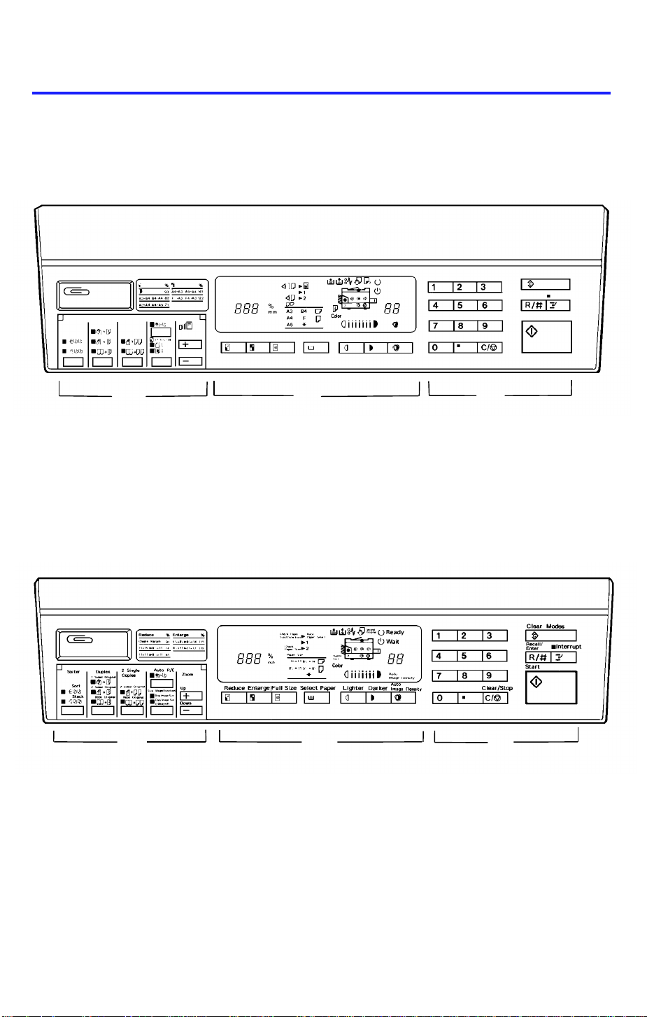
2. OPERATION PANEL
— A4/A3 Version —
C B A
1 December 1990
— LT/LDG Version —
Section A: See page 1-4.
Section B: See page 1-5 or 1-6.
BC
A
Section C: See page 1-7 or 1-8.
1-3
Page 6
2
1 December 1990
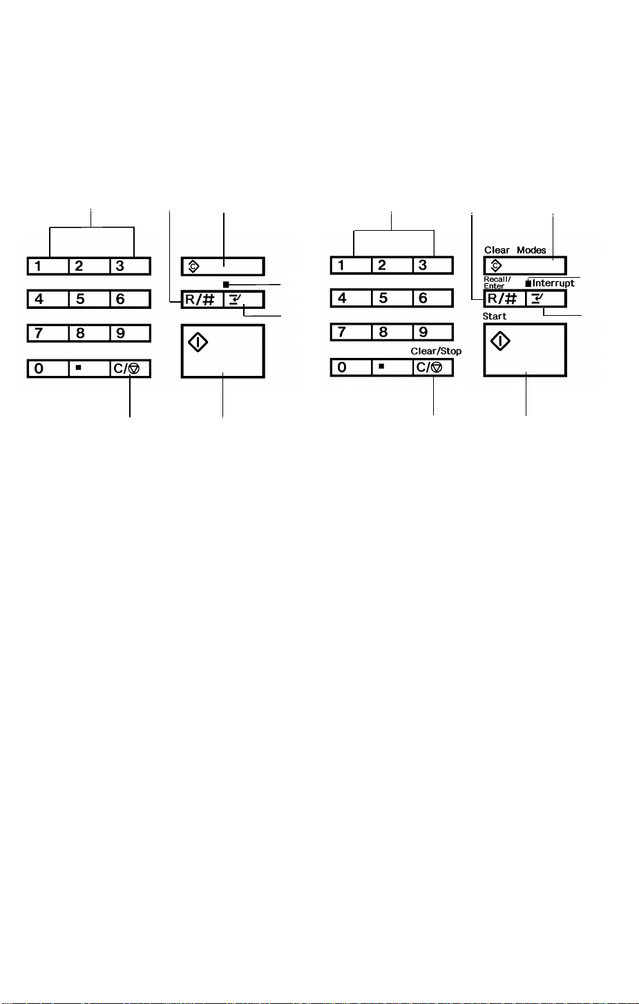
Section A —
— A4/A3 Version —
1
2
7
— LT/LDG Version —
3
4
5
6
1
3
4
5
7
6
1. Number Keys
The number keys are used to
enter the desired numb er of
copies. They are also used to
input the sizes of the original
and the copy image when in size
magnification mode.
2. Recall/Enter Key
Press to display the number of
copies entered. Also use to
enter or change da ta when in
size magnification mode.
3. Clear Modes Key
Press to clear all previously
entered settin gs and modes.
4. Interrupt Indicator
Lights when interrupt mode is
selected.
5. Interrupt Key
Press to make interrupt copies
during a copy run.
6. Start Key
Press to start copying.
7. Clear/Stop Key
Press to cancel the copy
number entered. While cop ying ,
press to stop copying.
1-4
Page 7

— Section B —
1
— A4/A3 Version —
1
2 3 4
5
6 7
1 December 1990
8 9 10
11
12
13
14
15
212223
1. Magnification Ratio Indicator
Shows the selected
reproduction ratio and data for
the Size Magnificatio n mod e.
2. Check Paper Size Indicator
Lights when improper paper
size is selected in the book
original mode or the duplex
mode. (Copying is impossible.)
3. Check Paper Size/Dir ection
Indicator
Blinks when the original size
do es not mat ch with the pap er
size or directio n. This indicator is
functional only wit h th e do cume nt
feeder. (Copying is possible.)
4. Auto Paper Select Indicator
Lights when auto paper select
mode is selected. This mode is
an optional feature with the
document feeder.
5. Duplex Unit Indicator
Lights when the duplex unit is
installed.
6. Load Paper Indicator
Lights when the cassette or the
paper tray in use runs out of
paper.
20
1819
1617
7. Add Toner Indicator
Blinks when it is time to change
the toner cartridge. When it is
continuously lit, the copier
cannot be used unt il a new
cartridge is installed.
8. Check Paper Path Indicator
Lights if there is a misfeed
within the machine.
9. Manual Feed Indicator
Lights when the manual feed
table is open.
10. Second Original Indicator
Lights when it is time to position
the second original on the
exposure glass when making
duplex copies.
— Light ON —
If copying has been completed,
press duplex key to cancel the
duplex mode and press start
key to eject copies.
— Light Blinking —
Press start key to eject copies.
11. Ready Indicator
Lights when the machine is
ready to make copies.
1-5
Page 8

24
1 December 1990
— LT/LDG Version —
1
2 3 4
5
6 7
8 9 10
11
12
13
14
15
212223
12. Wait Indicator
Lights when that the ma chin e is
not ready to copy.
13. Copy Counter
Displays the number of copies
entered. While copying, it shows
the number of copies made.
14. Auto Image Density Indicator
Lights when the copier is
automatically controlling image
density. If this indicator blinks,
refer to page 55.
15. Manual Image Density
Indicator
Shows the manually selected
image density. If this indicator
blinks, refer to page 55.
16. Auto Image Density Key
Press to select/cancel the
automatic image density mode .
20
1819
1617
18. Misfeed Location Displa y
Shows the location(s) of misfed
paper.
19. Color Copy Indicator
Lights if a color toner
development unit is insta lled .
20. Select Paper Key
Press to select the cassette or
the paper tray for paper feed, or
press to cancel auto paper
selection mode when the
document feeder is insta lled .
21. Full Size Key
Press to make copies the same
size as the originals.
22. Enlarge Key
Press to make enlarged copies.
23. Reduce Key
Press to make reduced cop ies.
17. Manual Image Density Keys
Use to cancel the automatic
image density mode and
manually select the image
density level.
24. Paper Size Indicator
Shows the size and direction of
the paper in use.
1-6
Page 9
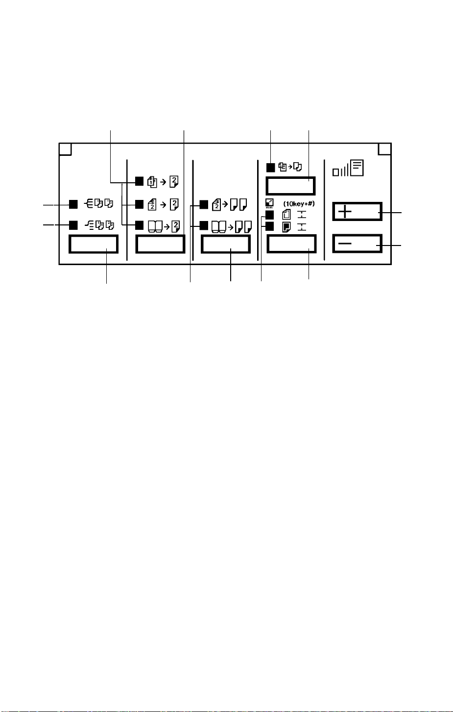
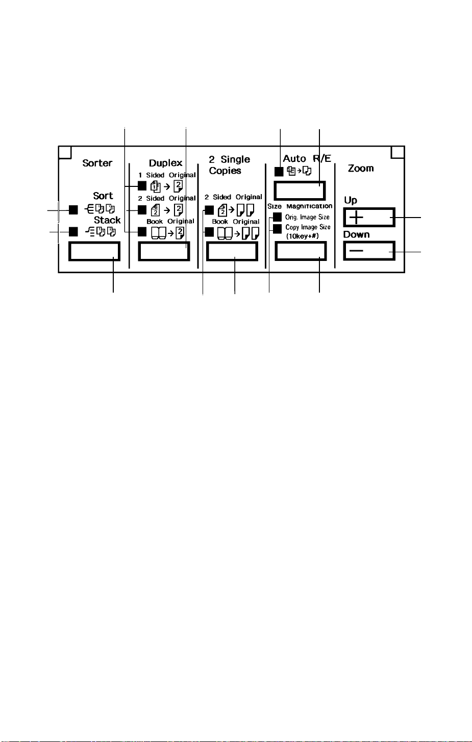
— Section C —
— A4/A3 Version —
5 4 6 7
1 December 1990
3
2
1
13
1. Sorter Key
Press to select the sort or stack
mode. The sort mode and stack
mode are optional feature s requ iring
a sorter.
2. Stack Indicator
Lights when in the stack mode.
3. Sort Indicator
Lights when in the sort mode.
8
9
1112
10
5. Duplex Indicators
Show which duplex copying mode is
selected.
6. Auto Reduce/Enlarge Indicator
Lights when in the auto
reduce/enlarge mode. This mode is
an optional feature requiring a
document feeder.
4. Duplex Key
Press to select one of three du plex
modes. These modes are optional
features requiring a duplex unit.
1-7
Page 10
2
1 December 1990
— LT/LDG Version —
5 4 6 7
3
1
7. Auto Reduce/ Enl arge Key
Press to select the auto
reduce/enlarge mode. This
mode is an optional feature
requiring a document feeder.
8. Zoom Up Key
Press to increase the
reproduction ratio in 1% step s.
9. Zoom Down Key
Press to reduce the
reproduction ratio in 1% step s.
10. Size Magnification Key
Press to select the size
magnification mode.
1213
11
10
11. Size Magnification Indicators
Lights when in the size
magnification mode; shows
when to enter the original size
and copy size data.
12. 2 Single Copies Key
Press to select one of two 2
single copies modes. The 2
Sided Original mode is an
optional feature requiring a
document feed er.
13. 2 Single Copies Indicators
Show which the 2 single cop ies
mode is selected.
8
9
1-8
Page 11

1 December 1990
1-9
Page 12
1 December 1990
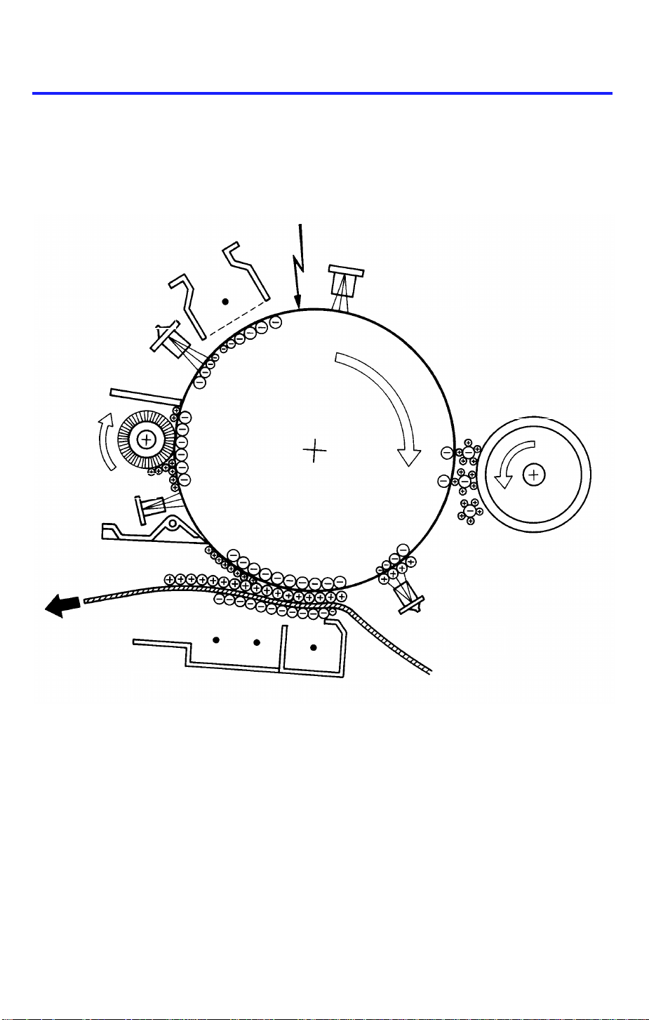
3. COPY PROCESSES AROUND THE DRUM
2. EXPOSURE
1. DRUM CHARGE
3. ERASE
9. QUENCHING
4. DEVELOPMENT
8. CLEANING
7. PAPER
SEPARATION
5. PRE-TRANSFER LAMP
(PTL)
6. IMAGE TRANSFER
1-10
Page 13

1 December 1990
1. DRUM CHARGE
In the dark, the charge corona unit gives a uniform negative charge to the organic
photoconductive (OPC) drum. The charge remains on the surface of the drum because the
OPC drum has a high electrical resistance in the dark.
2. EXPOSURE
An image of the original is reflected to the OPC drum surface via the optics assembly. The
charge on the drum surface is dissipated in direct proportion to the intensity of the reflected
light, thus producing an electrical latent image on the drum surface.
3. ERASE
The erase lamp illuminates the areas of the charged drum surface that will not be used for
the copy image. The resistance of the drum in the illuminated areas drops and the charge on
those areas dissipates.
4. DEVELOPMENT
Positively charged toner is attracted to the negatively charged areas of the drum, thus
developing the latent image. (The positive triboelectric charge is caused by friction between
the carrier and toner particles.)
5. PRE-TRANSFER LAMP (PTL)
The PTL illuminates the drum to remove all negative charge from the exposed areas of the
drum. This prevents the toner particles from being reattracted to the drum surface during
paper separation and makes paper separation easier.
6. IMAGE TRANSFER
Paper is fed to the drum surface at the proper time so as to align the copy paper and the
developed image on the drum surface. Then, a strong negative charge is applied to the back
side of the copy paper, producing an electrical force which pulls the toner particles from the
drum surface to the copy paper. At the same time, the copy paper is electrically attracted to
the drum surface.
7. PAPER SEPARATION
A strong ac corona discharge is applied to the back side of the copy paper, reducing the
negative charge on the copy paper and breaking the electrical attraction between the paper
and the drum. Then, the stiffness of the copy paper causes it to separate from the drum
surface. The pick-off pawls help to separate paper.
8. CLEANING
The cleaning brush removes most of the toner on the drum and loosens the remainder. Then
the cleaning blade scrapes off the loosened toner.
9. QUENCHING
Light from the quenching lamp electrically neutralizes the surface of the drum.
1-11
Page 14

1 December 1990
4. FUNCTIONAL OPERATION
1-12
Page 15
11
12
1 December 1990
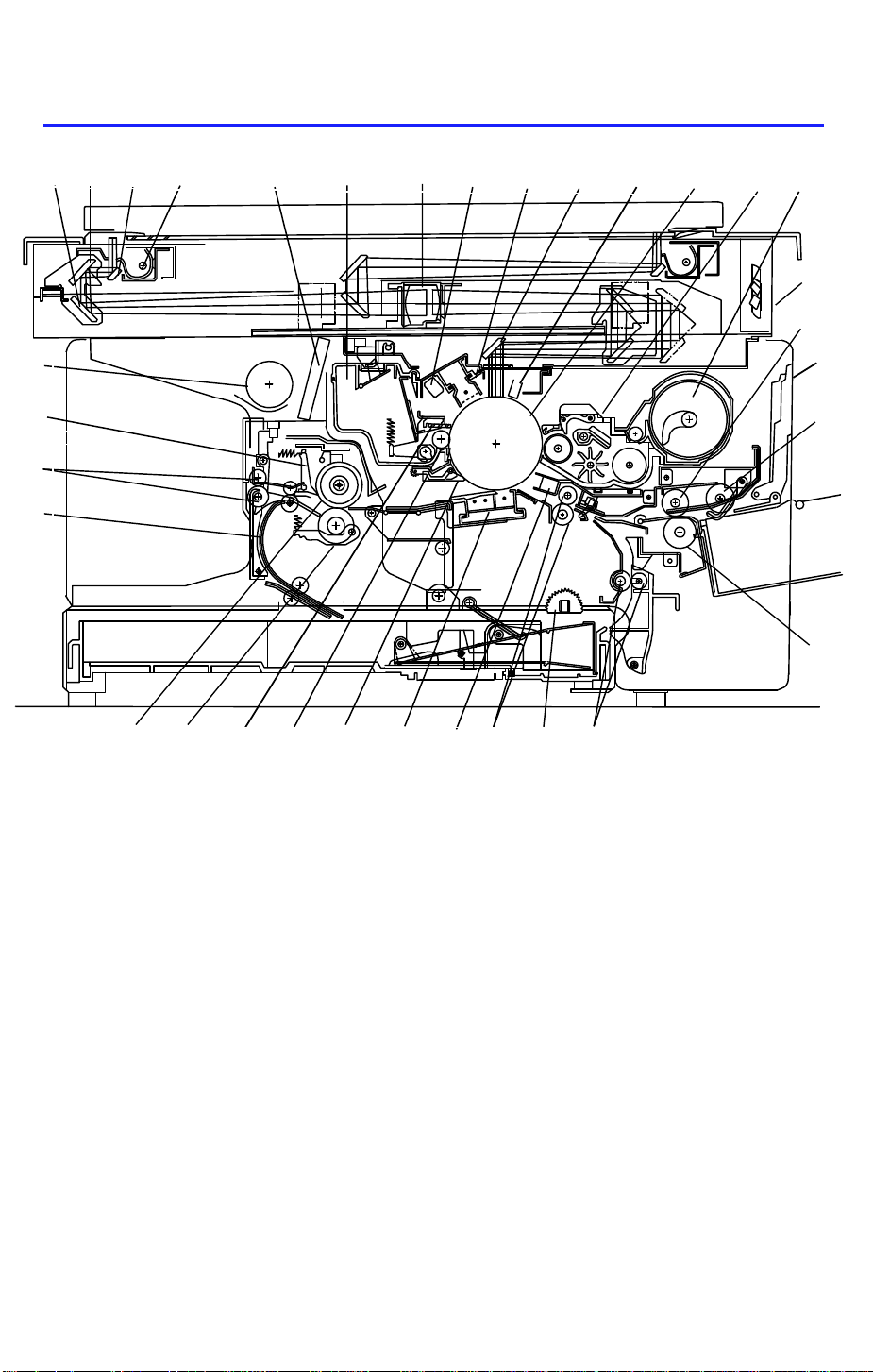
5. MECHANICAL COMPONENT LAYOUT
1
2 3
4
5
6 7
8 9 10
13 14
15
16
33
32
31
30
29
1. Third Mirror
2. Second Mirror
3. First Mirror
4. Exposure Lamp
5. Ozone Filter
6. Cleaning Unit
7. Lens
8. Quenching Lamp (QL )
9. Charge Corona Unit
10. Sixth Mirror
11. Erase lamp (EL)
12. OPC Drum
13. Development Unit
14. Toner Supply Unit
15. Optics Cooling Fans
16. Feed Roller
17. Manual Feed Table
18. Pick-up Roller
17
18
19
20212224 2325262728
19. Separation Roller
20. Relay Rollers
21. Semi-circular Feed Rollers
22. Registration Rollers
23. Pre-transfer Lamp (PTL)
24. Transfer and Separation Corona
Unit
25. Pick-off Pawls
26. Cleaning Brush
27. Cleaning Blade
28. Pressure Roller
29. Hot Roller
30. Duplex Turn Guide (Option)
31. Exit Rollers
32. Hot Roller Strippers
33. Exhaust Blower
1-13
Page 16
G24
G29
1 December 1990
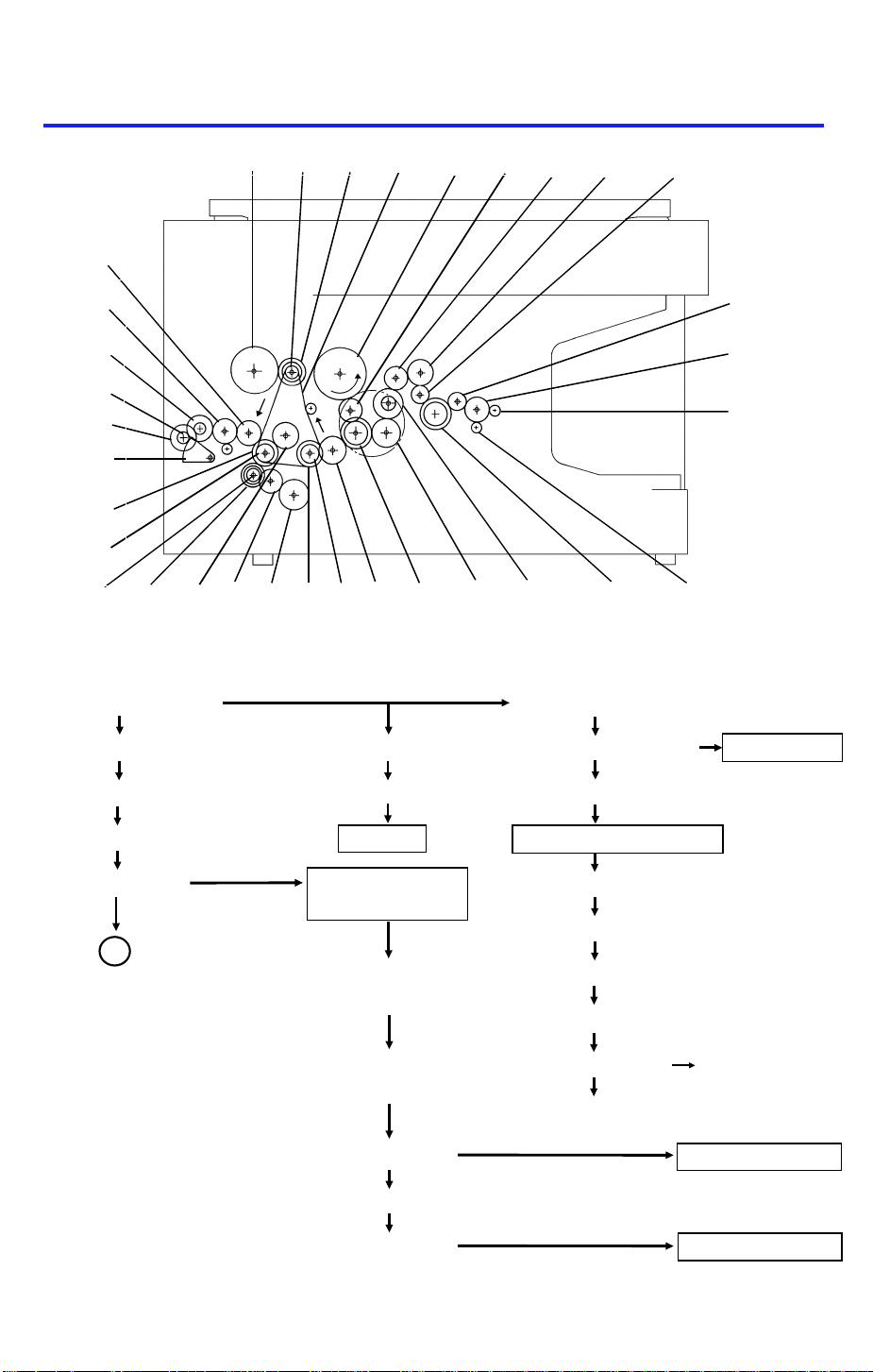
6. DRIVE LAYOUT
G17 BP2 G16 TB1 G19 G18
G5
G6
G7
G9
G8
G10
G4
BP3
G11G12G13
G14
G1: Main Motor Gear G20: Relay Gear
G3BP1G15
G22 G23
G25G21G20G1G2
G26
G27
G28
G2: Relay Gear G18: Relay Gear G21: Cleaning Drive Cleaning Unit
G3: Timing Belt Drive Gear G19: Drum Drive Gear G22: Relay Gear
BP1: Timing Belt Pulley Drum Fusing and Exit Section
TB1: Timing Belt Development G23: Relay Gear
Section
G24: Relay Gear
A
BP2: Timing Belt G25: Hot Roller Gear
Pulley
G26: Relay Gear
G16: Development G27: Relay Gear G29: Duplex Transport
CL Gear Gear (Option)
G28: Exit Roller Gear
Development CL Development Unit
G17: Toner Supply CL Gear
Toner Supply CL Toner Supply Unit
1-14
Page 17

1 December 1990
A
Paper Feed Section
BP3: Timing Belt Pulley
G11: Registration CL Gear G4: Relay Gear 2nd Feed Station
Registration CL G5: Relay Gear G12: Relay Roller
CL Gear
Registration Roller
1st Paper Feed CL G6: 1st Paper Feed CL Gear Relay Roller CL
1st Paper Feed CL G7: Relay Gear Relay Roller
G13: Relay Roller Gear
1st Paper Feed Rollers G8: Paper Lift CL Gear G14: Relay Gear
G15: 2nd Paper Feed
Paper Lift CL CL Gear
G9: Paper Lift Gear 2nd Paper Feed CL
G10: Sector Gear 2nd Paper Feed Roller
1-15
Page 18
789
10
2122242325
27
1 December 1990
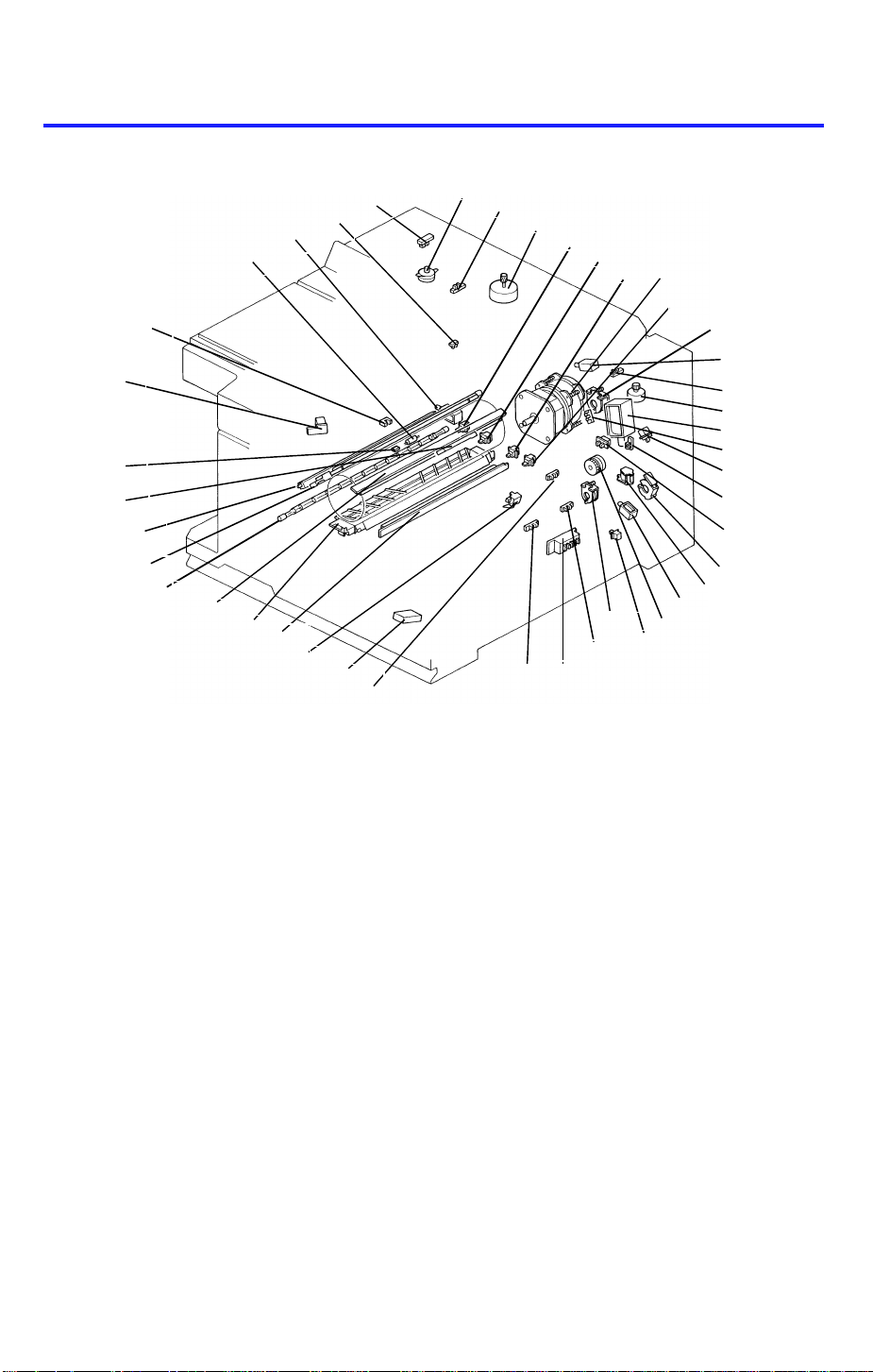
7. ELECTRICAL COMPONENT LAYOUT
39
41
32
40
38
36
37
34
42
35
43
31
30
1
4
3
5
6
13
11
12
15
16
14
17
18
19
20
2
26
33
29
28
1. Scanner H.P. Sensor
2. Lens Motor
3. Lens H.P. Sensor
4. Exit Sensor
5. Scanner Motor
6. 2nd Paper Size SW-1 (SW4)
7. 2nd Paper Size SW-2 (SW5)
8. 2nd Paper Size SW-3 (SW6)
9. 2nd Paper Size SW-4 (SW7)
10. Main Motor
11. Development CL Sol.
12. 4th/5th Mirror H.P. Sensor
13. Toner Supply CL Sol.
14. Toner End Sensor
15. 4th/5th Mirror Motor
16. Pick-up Roller Release Sol.
17. Manual Feed Table SW
18. Development Unit Set Sensor
19. Color Switch
20. Paper Lift CL Sol.
21. 1st Paper Feed CL Sol.
22. Relay Roller CL Sol.
23. Right Cover SW
24. Registration Clutch
25. 2nd Paper Feed CL Sol.
26. 1st Paper Size SW
27. 1st Paper End Sensor
28. 2nd Paper End Sensor
29. Cassette Lift Sensor
30. Registration Sensor
31. Pre-transfer Lamp (PTL)
32. ID Sensor
33. Total Counter
34. Erase Lamp (EL)
35. Transfer and Separation Corona Unit
36. Charge Corona Unit
37. Fusing Lamp
38. Quenching Lamp (QL)
39. Auto ID Sensor
40. Toner Overflow Sensor
41. Fusing Thermistor
42. Fusing Thermofuse
43. Tray Lock Sol.
1-16
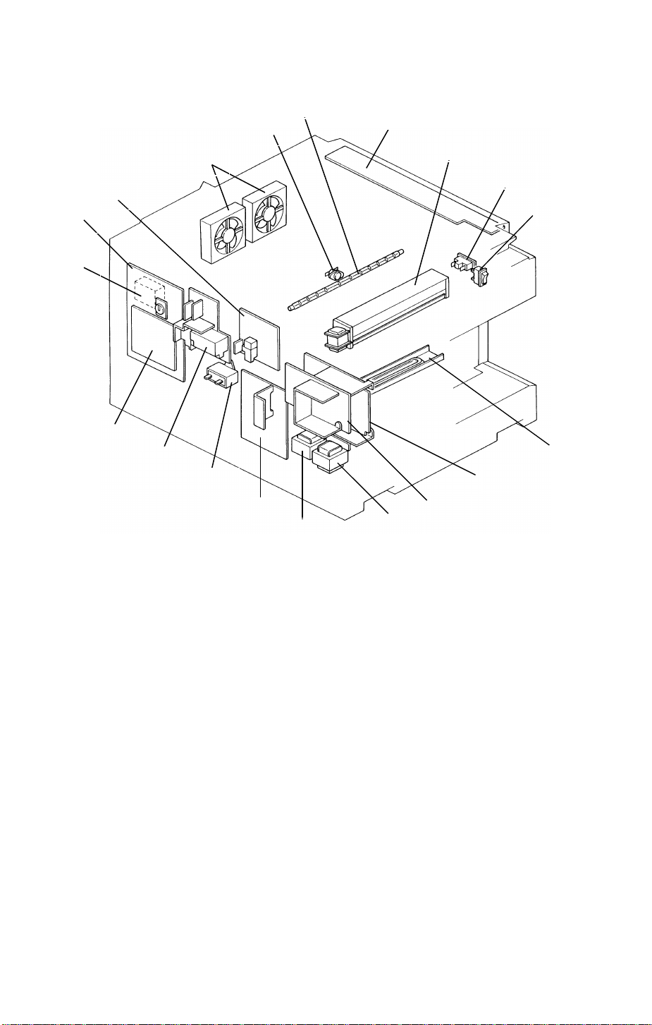
Page 19
55
1 December 1990
49
50
48
51
47
52
46
45
53
44
62
61
60
44. Key Counter (Option)
45. Main Board
46. CC/Grid/Bias Power Pack
47. Optics Cooling Fan Motors
48. Optics Thermoswitch
49. Exposure Lamp
50. Operation Panel Board
51. Exhaust Blower Motor
52. Cover Safety SW
53. Main SW
59
56
58
54. Drum Anti-condensation Heater
55. Main DC Power Supply Board
56. Optional DC Power Supply Board
(Option)
57. Optional Transformer (Option)
58. Main Transformer
59. AC Drive Board
60. Main Motor Capacitor
61. TC/SC Power Pack
62. Interface Board (Option)
57
54
1-17
Page 20

1 December 1990
8. ELECTRICAL COMPONENT DESCRIPTIONS
SYMBOL NAME FUNCTION INDEX
NO.
Motors
M1 Main Motor Drives all the main unit components except
for the optics unit and fans.
(115/220/240Vac)
M2 Scanner Motor Drives the scanners (1st and 2nd). (dc
stepper)
M3 Lens Motor Moves the lens position according to the
selected magnification. (dc stepper)
M4 4th/5th Mirror Mo-
tor
M5 Optics Cooling
Fan Motor-1
M6 Optics Cooling
Fan Motor-2
M7 Exhaust Blower
Motor
Move the 4th/5th mirror position according
to the selected magnification. (dc stepper)
Prevents built up of hot air in the optics
cavity. (24 Vdc)
Prevents built up of hot air in the optics
cavity. (24 Vdc)
Removes heat from around the fusing unit
and blower the ozone built up around the
charge section to the ozone filter.
Magnetic Clutch
MC1 Registration
Clutch
Drives the registration roller. 24
Solenoid
10
5
2
15
47
47
51
SOL1 Toner Supply
Clutch Solenoid
SOL2 1st Paper Feed
Clutch Solenoid
SOL3 2nd Paper Feed
Clutch Solenoid
SOL4 Pick-up Roller
Release Solenoid
SOL5 Paper Lift Clutch
Solenoid
SOL6 Tray Lock Sole-
noid
SOL7 Development
Clutch Solenoid
SOL8 Relay Roller
Clutch Solenoid
Drives the toner supply roller via the toner
supply spring clutch.
Starts paper feed from the first paper
station.
Starts paper feed from the 2nd paper
station.
a) After the paper is fed, releases the
pick-up roller from next paper. b) When the
manual feed table is used, releases the
pick-up roller from the table.
Lifts paper to the appropriate feed position. 20
Locks the paper tray/duplex unit. 43
Drives the development unit. 11
Drives the relay roller for the 2nd cassette
station.
1-18
13
21
25
16
22
Page 21

1 December 1990
SYMBOL NAME FUNCTION INDEX
NO.
Switches
SW1 Main Switch Supplies power to the copier. 53
SW2 Cover Safety
Switch
SW3 1st Paper Size
Switch
SW4 2nd Paper Size
Switch-1
SW5 2nd Paper Size
Switch-2
SW6 2nd Paper Size
Switch-3
SW7 2nd Paper Size
Switch-4
SW8 Color Switch Determines which color development unit is
SW9 Manual Feed Ta-
ble Switch
SW10 Right Cover
Switch
Cuts the ac power line. 52
Determines what size paper is in the first
cassette.
Determines what size paper is in the paper
tray.
Determines what size paper is in the paper
tray.
Determines what size paper is in the paper
tray.
Determines what size paper is in the paper
tray.
installed.
Detects when the manual feed table is
open.
Detects when the right cover is open. 23
Sensor
S1 Scanner Home
Position Sensor
Informs the CPU when the 1st scanner is at
the home position.
26
6
7
8
9
19
17
1
S2 Lens Home
Position Sensor
S3 4th/5th Mirror
Home Position
Sensor
S4 Registration
Sensor
S5 Exit Sensor Detects misfeeds. 4
S6 1st Paper End
Sensor
S7 2nd Paper End
Sensor
S8 Toner End
Sensor
S9 Toner Overflow
Sensor
S10 Paper Lift
Sensor
Informs the CPU when the lens is at the
home position (full size position).
Informs the CPU when the 3rd scanner
(4th/5th mirrors assembly) is at the home
position (full size position).
Detects misfeeds. 30
Informs CPU when the first cassette runs
out of paper.
Informs CPU when the paper tray runs out
of paper.
Detects when it is time to add toner. 18
Detects when the used toner tank is full. 40
Detects the correct feed height of the
cassette.
1-19
3
12
27
28
29
Page 22

1 December 1990
SYMBOL NAME FUNCTION INDEX
NO.
S11
S12 Development
Image Density
(ID) Sensor
Unit Set Sensor
Detects the density of the image on the
drum to control the toner density.
Sensors whether or not the development
unit is properly set.
Printed Circuit Board
PCB1 Main Board Controls all copier functions both directly
and through the other PCBs.
PCB2 AC Drive Board Drives all ac motors, the exposure lamp,
fusing lamp, quenching lamp, exhaust
blower motor.
PCB3 Main DC Power
Supply Board
PCB4 Auto Image
Density Sensor
(ADS)
PCB5 Optional DC
Power Supply
Board
PCB6 Interface Board Interfaces between the copier main board
PCB7 Operation Panel
Board
Rectifies 26 and 10 Vac input and outputs
dc voltages.
Senses the background density of the
original.
Rectifies 26 and 10 Vac input and outputs
dc voltasges.
and all the optional equipment’s main board.
Informs the CPU of the selected modes
and displays the situations on the panel.
32
18
45
59
55
39
56
62
50
Lamps
L1 Exposure Lamp Applies high intensity light to the original for
exposure.
L2 Fusing Lamp Provides heat to the hot roller. 37
L3 Quenching Lamp Neutralizes any charge remaining on the
drum surface after cleaning.
L4 Erase Lamp Discharge the drum outside of the image
area. Provides leading/trailing edge erase.
L5 Pre-transfer
Lamp
Reduces charge on the drum surface
before transfer.
49
38
34
31
Power Packs
P1 CC/Grid/Bias
Power Pack
P2 TC/SC Power
Pack
Provides high voltage for the charge
corona, grid, and the development roller
bias.
Provides high voltage for the transfer and
separation corona.
46
61
1-20
Page 23

1 December 1990
SYMBOL NAME FUNCTION INDEX
NO.
Heaters
H1 Drum Anti-
condensation
Heater
H2 Optics Anti-con-
densation Heater
Option
Counters
CO1 Total Counter Keeps track of the total number of copies
CO2 Key Counter
(Option)
Prevents moisture around the drum. 54
Prevents moisture from forming on the
optics.
made.
Used for control of authorized use. Copier
will not operate until installed.
Transformer
TR1 Main Transformer Steps down the wall voltage to 26 Vac and
10 Vac.
TR2 Optional
Transformer
Steps down the wall voltage to 26 Vac and
10 Vac for the document feeder and duplex
unit.
Others
TH Fusing
Thermistor
Monitors the fusing temperature. 41
N/A
33
44
58
57
TF Fusing
Thermofuse
TS Optics
Thermoswitch
C Main Motor Ca-
pacitor
Provides back-up overheat protection in the
fusing unit.
Provides back-up overheat protection
around the exposure lamp.
Start capacitor 60
42
48
1-21
Page 24
1 December 1990
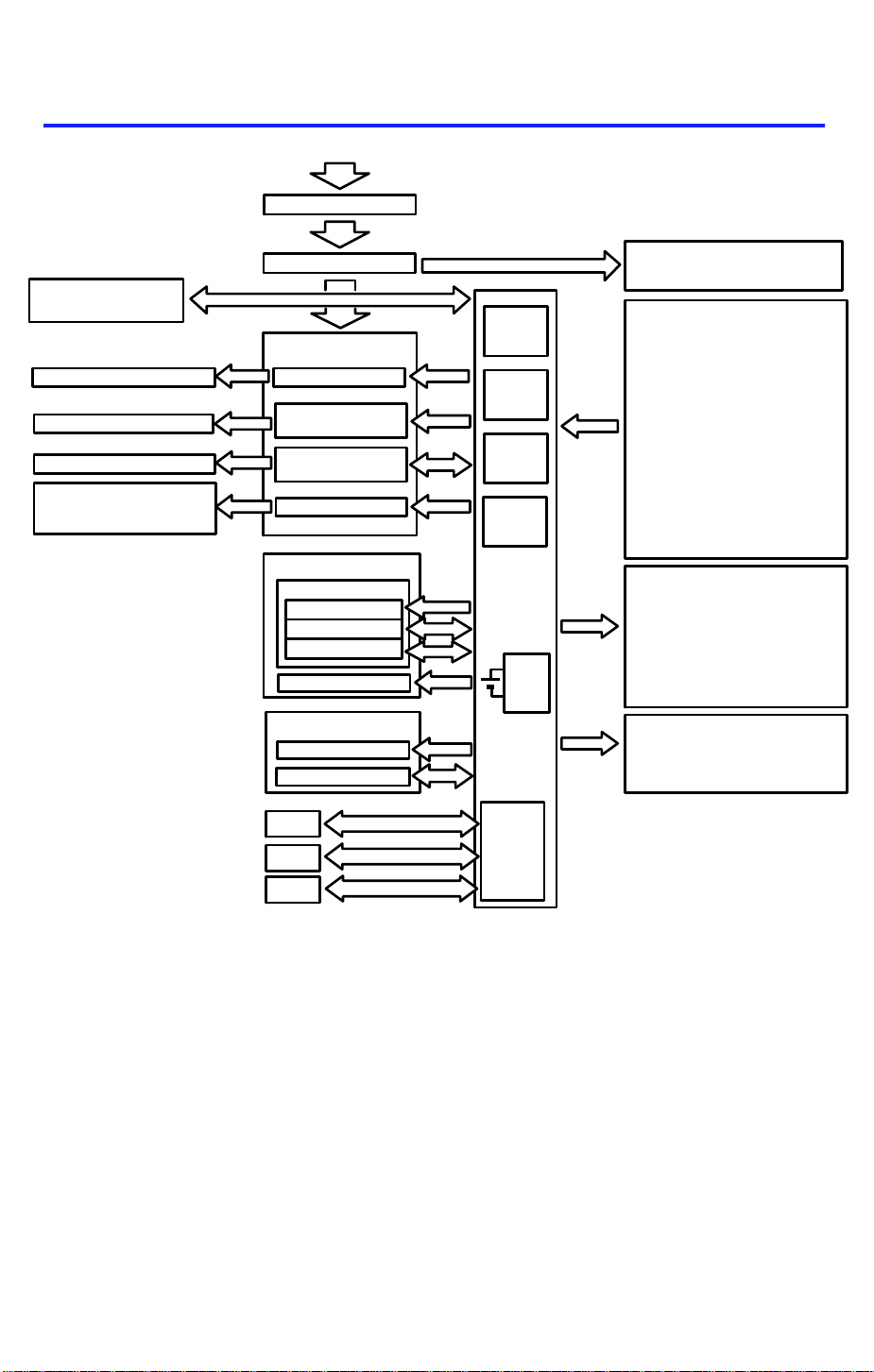
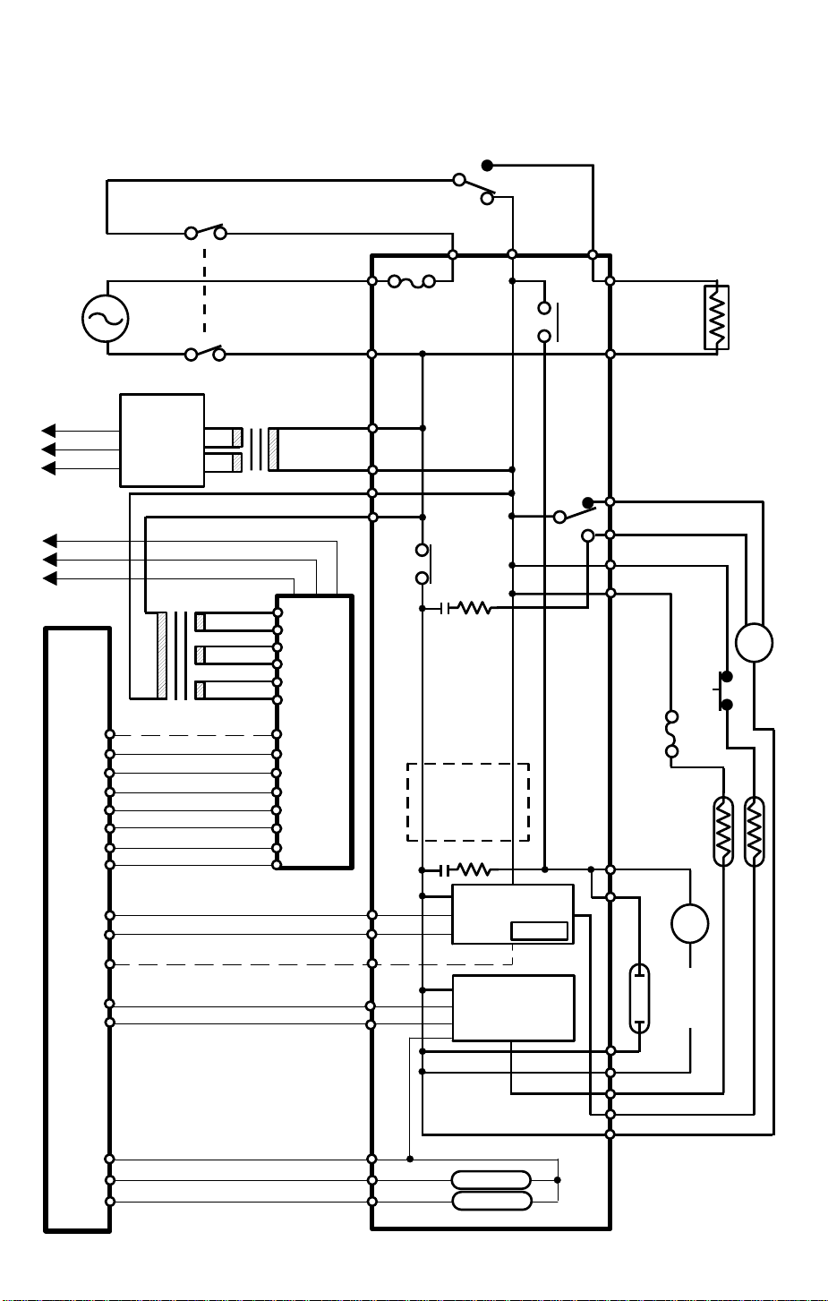
9. OVERALL MACHINE CONTROL
AC Power (115V or 220/240V)
Cover Safety Switch
Operation
Panel Board
Exhaust Blower Motor (L)
Fusing Lamp
Exposure Lamp
Main Motor
Quenching Lamp
Exhaust Blower Motor (H)
Main Switch
AC Drive Board
Power Relay
Fusing Lamp
Drive Circuit
Exposure Lamp
Drive Circuit
Main Motor Relay
Power Packs
CC/Grid/Bias P.P.
Charge Corona
Grid Voltage
Dev. Bias
TC/SC P.P.
Counters
Total Counter
Key Counter
IC 123
CPU
IC 105
I/O
IC 124
I/O
IC 111
ROM
Main Board
RAM
Board
Anti-condensation Heater
Sensors/Switches/Thermistor
Image Density Sensor
Registration Sensor
Cassette Lift Sensor
Exit Sensor
Auto ID Sensor
Scanner HP Sensor
Lens HP Sensor
4th/5th Mirror HP Sensor
Toner Overflow Sensor
Toner End Sensor
Color Switch
1st/2nd Paper Size Switches
1st/2nd Paper End Sensors
Right Cover Switch
Manual Feed Table Switch
Fusing Thermistor
Solenoids/Clutches
Pick-up Roller Release Sol.
Cassette Lift CL Sol.
1st/2nd Paper Feed CL Sol.
Relay Roller CL Sol.
Registration Clutch
Tray Lock Sol.
Development Drive CL Sol.
Toner Supply CL Sol.
Motors
Scanner Motor
Lens Motor
4th/5th Mirror
Optics Cooling Fan Motor
-Drum
-Optics
ARDF
Duplex
Sorter
Serial
Serial
Interface
Board
NOTE: The interface board is
connected to the copier main
board when the ARDF, duplex
unit and/or sorter is installed.
The above diagram shows the cont rol syste m of th is copie r in block form. The
CPU (IC123) on the main board controls the timing of all copie r’s ope rat ion
based on the CPU’s internal clock. The CPU monit ors the inp ut signals from
all sensors and controls the dc comp on ents directly or through two I/O chips
(IC 105 and IC 124). It also con tro ls a c components such as the fusing lamp,
exposure lamp, main motor qu en chin g lamp , an d exh au st blo wer motor (High
speed) directly via the ac drive board. The exh au st blo wer motor (Low speed)
is controlled via the I/O chip (IC 124) an d ac drive board. The cha rge corona,
grid voltage and development bias are powered by the same power pack
(P1) but are controlled separa te ly a s shown above. The main board has a
RAM board for the service program mode and misfeed recovery. A battery
backs up the power to the RAM board.
1-22
Page 25
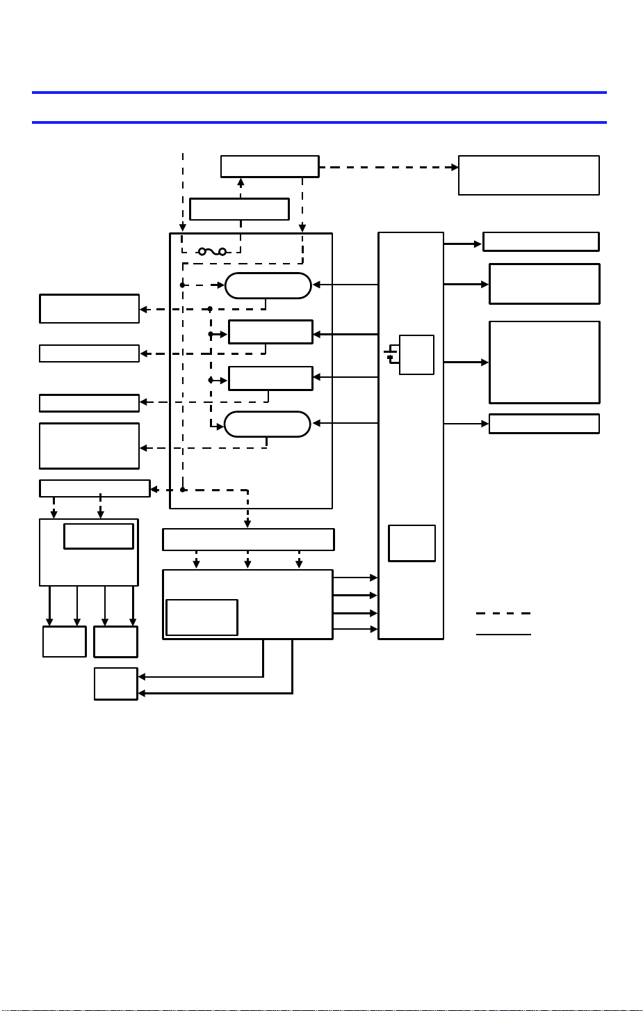
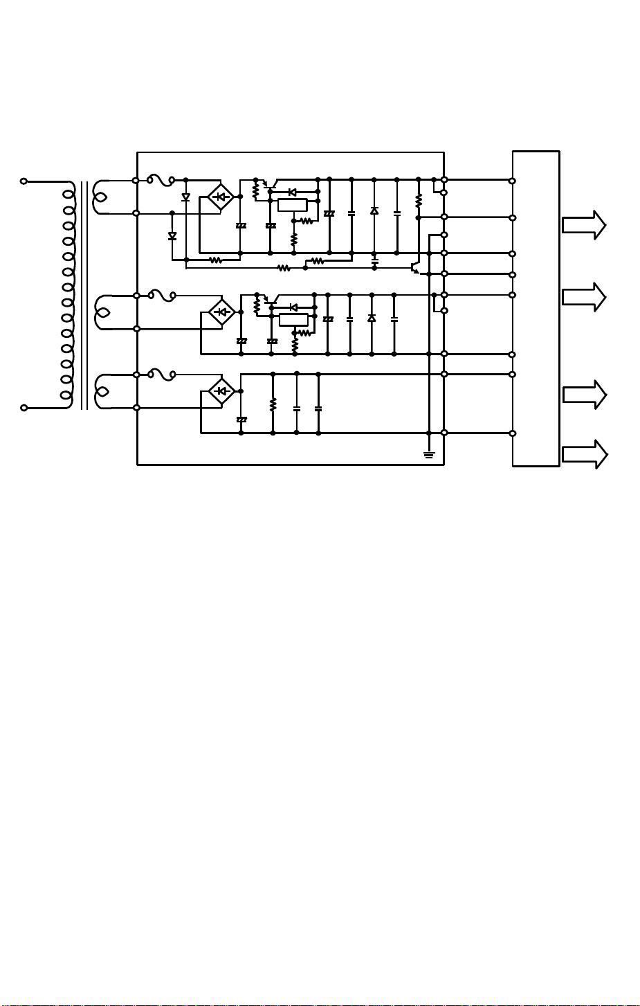
10. AC POWER AND DC POWER
DISTRIBUTION
AC Power (115V or 220/240V)
Main SW
Cover Safety SW
1 December 1990
Anti-condensation Heater
-Drum
-Optics (Option)
Exhaust Blower
Motor (L)
Fusing Lamp
Exposure Lamp
Main Motor
Quenching Lamp
Exhaust Blower
Motor (H)
Optional Transformer
26V AC 10V AC
FU100 (5V)
FU101 (24V)
Optional
DC Power Supply
Board
24V
(VA)5V(VC)
ARDF
24V
(VA)5V(VC)
Duplex
Fuse
Power Relay
(RA401)
Fusing Lamp
Drive Circuit
Exposure Lamp
Drive Circuit
Main Motor
Relay (RA402)
AC Drive Board
Main Transformer
10V AC 26V AC 26V AC
Main DC Power Supply Board
FU100 (5V)
FU101 (24V)
FU102 (30V)
24V (VA)
24V (VA)
24V (VA)
24V (VA)
30V (VM)
24V (VA)
5V (VC)
Zero
Cross
RAM
PCB
Main
Board
Interface
Board
Scan
Operation Panel Board
Signal
5V (VC)
Solenoids
Clutches
24V (VA)
30V (VM)
Power Packs
Lens Motor
4th/5th Mirror Motor
Optics Cooling Fan
Scanner Motor
Sensors
Switches
Interface Board
Motors
ac power
dc power
24V (VA)
Sorter
5V (VC)
When this copier is plugged in and the main switch is turned off, ac power is
supplied via the ac drive board to the anti-co nd ensation heater. When the
front cover and/or the exit cove r is open, the cover safety switch complete ly
cuts off power to all ac and dc components. The RAM board has a back up
power supply (dc battery) for the service program mode and misfeed job
recovery.
When the main switch is turned on, the ac power sup ply to the
anti-condensation heat er is cut of f an d ac power is supp lied to the ac drive
board. The main transformer receives wall outlet ac power through the ac
drive board and outputs 10 volts ac and 26 volts ac to the main dc power
supply board.
1-23
Page 26

1 December 1990
The main dc power supply board converts the 10 volts ac input to +5 volts
and a zero cross signal. There are two 26 volts ac inputs. The dc power
supply board converts them t o +24 volts an d +30 volts.
The +5 volts and +24 volts are supplied to both th e copier main board and
the sorter main board. The zero cross signal and +30 volts are supplied to
the copier main board.
The copier main board supplie s dc powe rs to all cop ier dc components. All
sensors, and switches plus the inte rfa ce bo ard ope rat e on +5 volts. The
scanner motor operate s on +30 volts. All other dc componen ts inclu ding the
power relay (RA401) and the main motor relay (RA 402) operate on +24 volts.
The ARDF and the duplex unit have a separat e dc power sup ply.
When the main board receives power, it act ivat es th e power rela y (RA401)
which then supplies ac power to the fusin g lamp drive circuit, and the
exposure lamp drive circuit on the ac drive board. The exhaust blower motor
begins rotating at low speed. The fusing lamp drive circuit receives a trigger
signal from the main board an d the fusing lamp lights. The exposure lamp
does not turn on until the main boa rd send a trigger pulse to the exp osure
lamp drive circuit.
When the Start key is pressed, the main bo ard ene rgize s the main mot o r
relay (RA402). Then, the ma in mot or an d the quenching lamp turn on an d th e
exhaust blower starts rotating at high speed.
When the main switch is turned off, power is cut off to the main board an d to
RA401, and the drum and optional anticondensa tio n he at ers are turned on.
The exposure lamp and the fusing lamp power lines are completely
disconnected from the lin e volt ag e.
1-24
Page 27
10.1 AC POWER DISTRIBUTION
Main SW
(SW1)
115V
220/240V
To DF and Duplex
[24] VA
[5] VC
[0] GND
To Sorter
[24] VA
[5] VC
[0] GND
ZERO
CROSS
[0] GND
[0] GND
[30] GND
[0] GND
[24] VA
[0] GND
[5] VC
Main
Board
(PCB1)
CN108-1
CN108-2
CN107-1
CN107-2
CN107-3
CN107-4
CN107-5
CN107-6
CN122-7
CN122-6
CN122-10
CN122-14
CN122-9
Optional
DC Power
Supply
Board
(PCB5)
TR1
Cover
Safety
SW (SW2)
10V AC
26V AC
CN103-1
CN103-2
CN103-3
CN100-1
CN100-2
CN100-3
CN100-4
CN100-5
CN100-6
CN102-2
CN102-1
CN101-1
CN101-2
CN101-3
CN101-4
CN101-5
CN101-6
TR2
T404
Fuse
T407
CN418-1
CN418-3
CN417-3
CN417-1
26V AC
26V AC
10V AC
DC
Power
Supply
Board
(PCB3)
CN401-8
CN401-9
CN401-5
CN401-1
CN401-6
T403 T401T402
RA401
AC
Drive
Board
(PCB2)
Noise Filter
Circuit
(220/240V
Only)
Exposure
Lamp Drive
Circuit
Fusing
Lamp Drive
Circuit
RA402-1
RA402-2
CN421
(220/240V
Only)
1 December 1990
CN411-1
CN411-2
Drum
Anti-condensation
Heater (H1)
CN420-3
CN420-2
Exhaust Blower Motor
CN419-1
Exposure Lamp
T405
Fusing
Lamp
Thermoswitch
Thermo-
fuse
169 C
(TF)
CN413-1
Main
Motor (M1)
CN415-1
(TS)
o
(L1)(L2)
M
Quench-
ing
Lamp
(L3)
LH
M
(M7)
CN122-13
CN122-12
CN122-11
CN401-2
CN401-3
CN401-4
Main Motor Relay
1-25
Power Relay
RA401
RA402
CN415-2
CN413-2
T406
CN419-2
CN420-1
Page 28
1 December 1990
10.2 DC POWER DISTRIBUTION
CN417
-1
115V
220/240V
CN417
-3
CN100
10VAC
CN100
CN100
26VAC
CN100
CN100
26VAC
CN100
DC Power Supply Board
FU100
-5
ON
-6
D101
FU101
-3
-4
FU102
-1
-2
ST100
D100
R104
ST101
ST102
R100
+
C100
R107
+
+
C110
Q100
R105
+
C101
Q102
+
C107
R108C110
D102
IC100
D104
IC101
R101
R102
R106
C114C111
C103+C104
+
C109 D105 C113
C108
D103
R103
C112
Q101C105
CN101-6CN107
CN103
-2
CN102
-2
CN103
-1
CN101
-5
CN102
-1
CN101
-4
CN103
-3
CN101-3CN107
CN101
-2
CN101
-1
(
(
(
Sorter
CN108
Sorter
CN107
CN108
CN107
Sorter
CN107
CN107
Main Board
-6
To
)
-1
To
)
-5
-2
-4
To
)
-3
-2
-1
[5]Vc
Zero
Cross
[0]GND
[0]GND
[24]VA
[0]GND
[30]VM
[0]GND
[24]VA
[5]VC
[30]VM
[0]GND
1-26
Page 29

SECTION 2
SECTIONAL DESCRIPTION
Page 30

1 December 1990
1. DRUM
1.1 OPC DRUM CHARACTERISTICS
An OPC has the characteristics of:
1. Being able to acce pt a high negat ive ele ctrical charge in the dark. (The
electrical resistance of a photoco nd uct or is high in the absence of light.)
2. Dissipatin g the ele ctrica l ch arg e whe n exp ose d to light . (Exp osu re to lig ht
greatly increases the conductivity of a photocond uctor.)
3. Dissipating an amount of charge in direct proportion to the intensity of the
light. That is, where stronger light is directed to the photoconductor
surface, a smaller voltage remain s on the OP C.
4. Being less sensitive to changes in temperatu re (whe n compared to
selenium F type drums). This makes it unnece ssary to monitor and
control the drum temperature.
2-1
Page 31

[F]
[D]
[E]
1 December 1990
1.2 DRUM UNIT
[H]
[G]
[B]
[C]
[A]
[C]
An organic photoconducto r drum [A] is used on this model.
A drum unit [B] is used to hold the drum to pre ven t stress on the drum. The
drum unit consists of an OPC drum, ID sensor [C] and pick-off pawls [D].
When the drum is replaced, and/or th e pick-o ff pawls an d/ or the ID sen sor
are cleaned, the drum unit must be removed from the copier as a unit.
The drum is driven by the main motor [H] through the main mot o r ge ar [E ], a
relay gear and the drum drive gear [F]. The pick-off pawls [ D] are always in
contact with the drum surfa ce. The ID sen sor is elect rically connected to the
ID sensor connector [G].
2-2
Page 32

1 December 1990
1.3 HANDLING THE DRUM
The organic photoconductor drum is compa ratively more sensitive to light
and ammonia gas than a selenium drum.
1. Never expose the drum to direct sunlight.
2. Never expose the drum to direct light of more than 1,000 Lux for more
than a minute.
3. Never touch the drum surface with bare hands. Wh en the drum surf ace is
touched with a finger or beco mes dirty, wipe with a dry cloth or clean with
wet cotton. Wipe with a dry clot h after cleaning with wet co tt on .
4. Never use alco ho l to clea n th e dru m; alcohol dissolves the drum surface.
5. Store the drum in a coo l, dry pla ce away from heat.
6. Take care not to scra tch the drum as th e dru m la yer is thin and is easily
damaged.
7. Never expo se th e drum to corrosive gases such as ammonia gas.
8. Always keep the drum in th e pro te ctive shee t whe n inserting or pulling the
drum unit out of the copier to avoid exposing it to bright light or direct
sunlight. This will protect the dru m from light fatigue.
9. Before inserting or pulling out the drum unit, the follo wing shou ld be
performed to avoid damaging the drum:
a) Remove the cleaning unit.
b) Remove the development unit.
c) Remove the charge corona unit.
d) Release the transport unit.
10. Before pulling out the drum unit, place a sheet of paper under the drum to
catch any dropped toner.
11. Drum initial setting (SP #66) must be performe d whe n a new drum is
installed.
NOTE: This is not necessary at installation of a new machine as the drum
initial setting is performed at the factory.
12. Dispose of the used drum acco rdin g to local regulations.
2-3
Page 33

1 December 1990
2. DRUM CHARGE
2.1 OVERVIEW
[A]
[C]
[C]
[B]
[A]
This copier uses a single wire scorotro n and a highly sensitive OPC drum [A].
The corona wire [B] genera tes a corona of negative ions wh en the CC/B/G
power pack applies a high voltage . A sta inless steel grid plate [C] makes the
corona charge uniform. The dru m coat ing receives a uniform negative charge
as it rotates past the corona unit.
The exhaust blower, locat ed abo ve the cop y exit, causes a flow of air from
the upper area of the deve lopment unit through the charge corona unit. This
prevents uneven build -up of negative ions that ca n cau se un eve n image
density. The exhaust blower runs at half speed when in the stand-by
condition and runs at fu ll sp ee d while copying.
The exhaust blower has an ozone filte r (a ctive carbo ns) which adsorbs ozone
(O3) generated by th e coro na discharge. The ozone filter de crea ses in
efficiency over time as it adsorbs ozo ne. The ozone filter should be replace d
at every 60,000 copies.
The flow of air around the charge corona wire may deposit paper dust or
toner particles on the corona wire . The se pa rticle s may in te rfe re with
charging and cause low density ba nds on cop ies. The wire cleaner cleans
the corona wire when the op erator slides the corona unit in and out .
2-4
Page 34

1 December 1990
2.2 CHARGE CORONA WIRE CLEANER MECHANISM
[B]
[A]
[D]
[C]
Pads [A] above and below th e charge corona wire clean the wire as the
charge unit is manually slid in and out.
The cleaner pad bracket [B ] rotates when the charge unit is fully extended
and the bracket is pulled up against the rear block [C]. This moves the pads
against the corona wire (see illustra tio n). If the charge unit is not fully
extended, the pads do not tou ch th e corona wire.
The pads move away from the wire when the charg e unit is fu lly inse rte d an d
the cleaning bracket is pushed against the front block [D].
After copier installatio n the key operator should be instructe d ho w to use this
mechanism when copies have whit e stre aks.
2-5
Page 35

1 December 1990
2.3 CHARGE CORONA CIRCUIT
VA [24]
VC [5]
CC Trig [ 24]
Grid Trig (PWM) [ 0 0/5]
Grid FB
GND [0]
CN112-8
CN112-7
CN112-6
CN112-5
CN112-4
CN112-3
CN112-2
CN112-1
CN1-1
CN1-2
CN1-3
CN1-4
CN1-5
CN1-6
CN1-7
CN1-8
CC/Grid/Bias
Power Pack
(P1)
TC
TG
TB
Charge
Corona Wire
Grid
Development
Roller
Main Board (PCB 1)
The main board supplies +24 volt s to th e CC/G rid/Bias power pack at CN1-1
as the power supply source. About 0.44 seconds af te r t he Sta rt key is
pressed, the CPU drops CN1-3 fro m +24 volts to 0 volts. This energizes the
charge corona circuit within th e CC/G rid/Bias power pack, which applies a
high negative voltage of approximately –5.6 kv to the charge corona wire.
The corona wire then generates a negative corona charge.
The grid limits the charge voltage to ensu re th at the charge does not fluctuate
and an even charge is applied to the drum surf ace .
The grid trigger pulse applied to CN1-5 is a pulse width modulated signa l
(PWM signal). This signal is not only a trigger signal; it also chan ges the
voltage level of the grid. As the width of the pulse ap plie d incre ases, the
voltage of the grid also increase s. The CPU monitors the grid voltage at
CN1-7 and controls the wid th of th e grid trigger pulses based on this
feedback.
2-6
Page 36

1 December 1990
2.4 GRID VOLTAGE CORRECTION
There are two grid voltage correction factors. These correct fo r increases in
the drum residual voltage (Vr). The first such fact or, Vr correct ion, is done
every 1,000 copies. Vr correction is based on the data of the dru m coun te r
(SP #69) and the Vr correction ratio (L) (SP #67). The second factor, Vp
correction, corrects for changes in the photo con ductor’s chargeability. (The
chargeability of a new OPC drum may change after inst alla tio n, but this
stabilizes at around 2,000 copie s.) Vp correction is based on the drum
counter. The counter re set s to "0" whe n dru m initia l se tt ing (S P mod e #66) is
performed.
Both correction factors are applied to the copy pro cess as fo llows:
1. Image area
Grid Voltage = –920 volts
+
Vr Correction Factor.
Vr Correction Factor
L = Vrp/Vsg x 100 (Vr correction ratio)
2. Non-image are a
Grid Voltage = 0 volts (Fixed)
L Change of Grid Voltage
100 to 89 (%)
88 to 76 (%)
75 to 62 (%)
61 to 45 (%)
44 to 0 (%)
±0 (volts)
–40 (volts)
–80 (volts)
–120 (volts)
–160 (volts)
Vrp: ID sensor output for Vr correction pattern
Vsg: ID sensor output for bare drum
2-7
Page 37

1 December 1990
3. ID sensor pa tt ern area
Grid Voltage = –620 volts
Vp Correction Factor
+
Drum Counter
0 to 999 (copies)
1,000 to 1,999 (copies)
Over 2,000 (copies)
4. Vr correction pattern area
Grid Voltage = –500 volts (Fixed)
Vp Correction Factor
Black Color
±0 (volts)
–20 (volts)
–40 (volts)
±0 (volts)
±0 (volts)
–20 (volts)
2-8
Page 38

3. OPTICS
3.1 OVERVIEW
1 December 1990
[C] [B] [A] [E] [H] [F]
[D] [I] [G]
During the copy cycle, an image of the original is reflecte d onto the drum
surface through the optics assembly as follows.
Light Path:
Exposure Lamp [A] → Original → First Mirror [B] → Second Mirror [C]
→ Third Mirror [D] → Lens [E] → Fourth Mirror [F] → Fifth Mirror [G]
→ Sixth Mirror [H] → Drum [I]
[J]
The two optics cooling fans [J] draw cool air into the optics cavity. The air
flows from the right to the left in the optics cavity and exhausts through the
vents in the left cover. These fans operate during the copy cycle.
This copier has six standard reprod uct ion ratios: Three reduction ratios, two
enlargement ratios, and full size. It also has a zoom fun ctio n. The operator
can change the reproduction ratio in one perce nt steps from 50% to 200%.
Stepper motors are used to cha nge th e positio ns of the le ns and mirrors.
Separate motors a re use d be cause the wide range of reproduction ratios
makes it mechanically difficult fo r one moto r t o positio n both the lens and
mirrors. A stepper motor is also used to drive th e scanner. This motor
changes the scanner spe ed according to the reproduct ion ratio.
The thermoswitch opens at 130 oC and removes ac power to the exposure
lamp to prevent overh eating. The thermoswitch can be reset ma nu ally whe n
the exposure lamp area cools.
2-9
Page 39

[F]
1 December 1990
3.2 SCANNER DRIVE
[B]
[D]
[E]
[C]
[A]
[G]
3.2.1 1st and 2nd Scanner Drive Mechanism
This model uses a stepping moto r [A] to drive the scanners. Both ends of
each scanner are driven to pre vent skewing. The scanners have slid ers [B ],
which ride on guide rails.
The scanner home position is detected by the home position sensor [C]. The
scanner return position is determine d by cou nt ing the scann er mot or drive
pulses.
The first scanner [D], which consists of the exposu re lamp and the first mirror,
is connected to the scanner drive wire by the wire clamps [E]. The second
scanner [F], which consists of th e seco nd and third mirro rs, is conn ect ed to
the scanner drive wire by movable pulleys (the second scann er pulley [G ]).
The pulley moves the second scanne r at ha lf th e velo city of the first scanner.
This is to maintain the focal distance between the original and the lens during
scanning. This relationship can be expressed as:
V1r = 2 (V2r) = VD/r
where r = Reproduction ratio
V1r = First scann er velo city (whe n the reproduction ratio
is "r")
V2r = Seco nd scann er velo city (whe n the reproduction ratio
is "r")
VD = Drum peripheral velocity (12 0 mm/s)
2-10
Page 40

3.3 LENS DRIVE
: Reduction
: Enlargement
[D]
1 December 1990
[C]
[E]
[B]
[G]
[A]
[F]
3.3.1 Lens Drive
The lens motor [A] (stepper motor) changes the lens [B] position through the
lens drive wire [C] in accordance with the selected rep rod uction ratio to
provide the proper optical distan ce between the lens and the drum surface.
The rotation of the lens drive pulley moves the lens back and forth in discrete
steps. The home position of the len s is dete cte d by th e home position sensor
[D]. The main board keeps track of the lens position based on the number of
pulses sent to the lens mo to r.
3.3.2 Shading Mechanism
The shading plate s [E] are installed on the lens housin g [F] and are slid open
and shut by the shading cam [G]. This shading mechanism adju sts the
horizontal light inten sity, which be come s une ven in redu ctio n mode, when the
light at both edges is more intense. The shading plates close in reduction
mode to even out the ligh t int en sity.
2-11
Page 41

(93% → 71/65%)
1 December 1990
3.3.3 Lens Positioning
[A] [C]
Home Position (100%)
(100% → 141/155%)
[D]
[B]
(141/155% → 71/65%)
(71/65% → 93%)
(71/65% → 141/155%)
(141/155% → 122/129%)
(122/129% → 100%)
(100% → 71/65%)
(71/65% → 100%)
Reduction SideEnlargement Side
The lens home position sensor [A] informs the main board when the lens is at
full size position (home position). The main board dete rmine s the lens sto p
position in reduction an d en largement modes by countin g the number of
steps the motor makes with reference to the lens home position. When a new
reproduction ratio is select ed , th e lens [B] moves directly to the selected
magnification position.
The lens home position is registe red each time the lens starts from or passes
through the lens ho me posit ion sensor. As the lens moves fro m t he
enlargement side to the reduction side, the sensor registers the home
position. This occurs when the actu at or plate [C] enters the lens home
position sensor.
A small vibration can be observed when the lens moves through home
position from the red uct ion side to the enlargemen t side because the lens is
going in the wrong direction to register the home positio n. The len s
overshoots the home position by on ly one pulse before going back to register
the home position.
The lens always stops while moving from lef t to rig ht (as viewed from the
front) to minimize the erro r cause d by mechanical play in the drive gears [D].
2-12
Page 42

3.4 4TH AND 5TH MIRROR DRIVE
[A]
(71/65% → 100%)
Home Position (100%)
1 December 1990
[B]
(100% → 141/155%)
(141/155% → 71/65%)
(71/65% → 93%)
(93% → 71/65%)
(71/65% → 141/155%)
(141/155% → 122/129%)
(122/129% → 100%)
(100% → 71/65%)
3.4.1 Drive
The 4th/5th mirror drive motor (stepper motor) changes the 4th/5th mirror
assembly position throug h th e pin ion gears [A] and the rack gear [B] in
accordance with the selected reproduction ratio to provide the proper optical
distance between the lens and drum surf ace .
3.4.2 Positioning
The positioning mechanism is similar to that of lens po sitio ning, as shown in
the above positioning chart. The scanner always stops while moving from
right to left (as viewed from the fron t).
2-13
Page 43

1 December 1990
3.5 STEPPER MOTOR CONTROL CIRCUI T
Scanner
H.P. Sensor
(S1)
Lens
H.P. Sensor
(S2)
4th/5th
Mirror
H.P. Sensor
(S3)
CN122-3
CN122-4
CN122-5
CN102-7
CN102-8
CN102-9
CN102-10
CN102-11
CN102-12
CN806-3
CN806-2
CN802-1
CN824-3
CN824-2
CN824-1
CN826-3
CN826-2
CN826-1
[0] GND
[ 5]
Scanner H.P.
[5] VC
[0] GND
[ 5] Lens H.P.
[5] VC
[0] GND
[ 5] 4th/5th
Mirror H.P.
[5] VC
A [ 30 0/30]
A [ 30 0/30]
B [ 30 0/30]
B [ 30 0/30]
A [ 24 0/24]
A [ 24 0/24]
B [ 24 0/24]
B [ 24 0/24]
A [ 24 0/24]
A [ 24 0/24]
B [ 24 0/24]
B [ 24 0/24]
Main Board (PCB1)
VM [30]
VM [30]
VA[24]
VA[24]
VA[24]
VA[24]
CN105-1
CN105-2
CN105-3
CN105-4
CN105-5
CN105-6
CN102-1
CN102-2
CN102-3
CN102-4
CN102-5
CN102-6
CN106-1
CN106-2
CN106-3
CN106-4
CN106-5
CN106-6
CN825
6
5
4
3
2
1
Scanner
Motor
(M2)
1
2
3
4
5
6
Lens
Motor
(M3)
4th/5th
Mirror
Motor
(M4)
Step 1 2 3 4 5 6 7 8
A
B
A
B
ON
OFF
ON
OFF
ON
OFF
ON
OFF
Com.
1
2 3 4
A
A
B
Com.
6
5
B
The scanner motor, th e len s mo to r, an d the 4th/5th mirror motor are all
stepper motors. The scanner mot or op era te s on +30 volts. Bot h the len s
motor and the 4th/5th mirror motor operate on +24 volt s. The stat ors of these
stepper motors have four coils (labeled A, B, A, B above), and th e rotor is
made of permanent magnets. Pulse signals energize the four coils as shown
in the above illustration. The roto rs o f these motors turn in discrete steps, and
48 steps are required for on e revo lution.
2-14
Page 44

1 December 1990
The lens motor and the 4th/5th mirro r moto r move at a const an t spe ed , bu t
the scanner motor speed varies acco rdin g to the reproduction ratio. The CPU
changes the pulse rate (pulse per second) to adjust the speed for the
selected reproduction ratio.
HP sensors inform the main board when the first scanner, lens, and 4th/5t h
mirror assembly reach their respective home positions. The main board
determines the stop position by count ing the numb er of steps the moto r
makes with reference to the home position.
2-15
Page 45

70 mm
B
Sampled area
A
[A]
[C]
40 mm
1 December 1990
3.6 AUTOMATIC IMAGE DENSITY DETECTION
[B]
Light from the exposure lamp is reflected from the original and tra vels to the
lens [A] via the mirrors. The auto ID senso r [B] , a phot odiode, is mounted on
the upper front frame. The sensor cover [C] has a hole in it to allow light to
fall directly onto the sensor. Sampling starts 10 millimete rs from th e leadin g
edge of the original and continued to 40 millimeters from the lead ing edge of
original in full size mode.
The length A and B in each rep roduction ratio are calcu lat ed as follows:
A=
The photosensor circuit converts the light intensity to a voltage. The dete cte d
10 mm
Reproduction Ratio (%)
x100
B=
Reproduction Ratio (%)
x100
voltage is amplified and sent to the main PCB. The CPU stores the voltage of
each sampled point in RA M. It the n comp utes the image density of th e
original from the maximum sample volt ag e and changes the development
bias accordingly. (See page 2-3 0 for d et ails. ) The exposure lamp voltage is
constant regardless of the image density of the origin al. (See page 2-1 8 for
details.)
2-16
Page 46

1 December 1990
3.7 EXPOSURE LAMP VOLTAGE CONTRO L
The main board controls the expo sure lamp voltage through the ac drive
board. The exposure lamp voltage is based on the base lamp voltage and
various correction factors. The exposure lamp data settin g dete rmine s the
base lamp voltage. The followin g table gives th e appro ximate lamp voltage
for each data setting.
Exposure Lamp Data/Voltage Reference Table
Exposure Lamp Voltage
Exposure
Lamp Data
100 57.1 105.9 126 71.9 133.4
101 57.6 106.9 127 72.5 134.5
102 58.2 108.0 128 73.0 135.5
103 58.8 109.1 129 73.6 136.6
104 59.3 110.1 130 74.2 137.6
105 59.9 111.2 131 74.7 138.7
106 60.5 112.2 132 75.3 139.8
107 61.1 113.3 133 75.9 140.8
108 61.6 114.4 134 76.5 141.9
109 62.2 115.4 135 77.0 142.9
110 62.8 116.5 136 77.6 144.0
111 63.3 117.5 137 78.2 145.1
112 63.9 118.6 138 78.7 146.1
113 64.5 119.6 139 79.3 147.2
114 65.0 120.7 140 79.9 148.2
115 65.6 121.8 141 80.5 149.3
116 66.2 122.8 142 81.0 150.4
117 66.8 123.9 143 81.6 151.4
118 67.3 124.9 144 82.2 152.5
119 67.9 126.0 145 82.7 153.5
120 68.5 127.1 146 83.3 154.6
121 69.0 128.1 147 83.9 155.6
122 69.6 129.2 148 84.4 156.7
123 70.2 130.2 149 85.0 157.8
124 70.8 131.3 150 85.6 158.8
125 71.3 132.4
115V machine
(Standard)
220/240V
Exposure
Lamp Data
machine
Exposure Lamp Voltage
(Standard)
115V machine
220/240V
machine
NOTE: Exposure lamp rating: 100V machine : 85V/300W
115V machine: 97V/300W
220/240V machine: 180V/330W
2-17
Page 47

1 December 1990
The exposure lamp voltage consist s of th e followin g 3 factors:
Exposure lamp voltage = Base lamp voltage factor
+
Reproduction ratio correction factor
+
Drum wear correction factor
3.7.1 Base Lam p Voltage Factor In Manual Image Densi ty Control
Darker Lighter
Manual ID Level 1234567
Exposure Lamp Data Vo –4
Vo ±0 Vo ±0 Vo ±0
Vo +4 Vo +8 Vo +12
The above table shows changes in the expo sure la mp data in manual image
density mode.
SP mode #48 sets the expo sure lamp da ta for level 4 (Vo) of manual imag e
density mode. A value from 100 to 150 can be select ed .
3.7.2 Base Lamp Voltage Factor In Auto Image Density Contr ol
In auto ID mode, the CPU selects the level 4 (Vo) exposu re lamp dat a
regardless of the input from the auto image density sensor. When the auto
image density level is set to lighter in SP mod e #34, the expo sure lamp da ta
changes to that of man ua l ID level 5 as sho wn be low. When the auto image
density level is set to darker, the develop men t bias shifts +40 volts. Only the
development bias varies acco rding to the input from the auto imag e density
sensor. (See page 2-30).
Auto Image Density Level (SP mode #34)
Auto Image Density
Level
Normal 0
Darker 1
Lighter 2
SP Data
(SP mode #34)
Exposure Lamp Data
Same as level 4
(Vo ±0)
Same as level 4
(Vo ±0)
Same as level 5
(Vo +4)
Development Bias
Shift
±0 volts
+40 volts
±0 volts
2-18
Page 48

3.7.3 Reproduction Ratio Corr ection Factor
Exposure
Lamp
Data
+10
+5
+0
-
1 December 1990
Lighter
50 100
62
140 150 160 180 200 (%)
Reproduction Ratio
For the reduction and en larg ement reproduction ratios the light path is longe r
than for the full size reproduct ion ratio. For this reason, the expo sure lamp
voltage is increased whe n red uction or enlargemen t is selected. The above
chart shows the exposu re lamp data at various reprodu ctio n ratios.
2-19
Page 49

1 December 1990
3.7.4 Drum Wear Correction Factor
Exposure
Lamp
Data
+10
(Max)
SP #61 = 0
+5
+0
-
0 10203040 60708090 110 (Hours)
50 100
SP #61 = 1
Main Motor On Time
To compensate for OPC drum wea r ca use d by con ta ct with the cleaning
brush, the exposu re lamp voltage is increased at set intervals of main motor
ON time. When SP mode #61 is set to 0, exp osu re lamp dat a is increa sed 1
at 10-hour intervals. When SP mode #61 is set to 1, the dat a is increa sed 1
at 20-hour intervals. The total increase cannot excee d 8.
2-20
Page 50

3.8 EXPOSURE LAMP CONTROL CIRCUI T
Main Board (PCB1) AC Drive Board (PCB2)
1 December 1990
CN108-1
Zero
Cross
240V
T402
CN419-1
Thermo-
SW (TS)
Exposure
Lamp
(L1)
CN419-2
T407
A
D
AC115V
AC220V
AC240V
B
CPU
(EXPO)
E
Feed back signal
+24V
TP111
0V
CN122-7
CN122-6
CN122-13
CN401-8
CN401-7
CN401-2
VR401
R403
R401
C
24V
0V
Trigger Pulse
CN122-10
AC power
Zero cross
Trigger pulse
Lamp power
Feedback
signal
CN401-5
A
B
C
D
E
PC401
R404
R404
C401
ZD
401ZD402
ZD
403ZD404
R411
TRC401
D401
R406
R413
DB401
CR401
L401
L402
CN421
220V
220V Only
TR401
C411
Feedback
The main board sends lamp trigger pu lses to the ac drive board from
CN122-10. PC401 activates TRC401, which provid es ac power to the
exposure lamp, at the trailing edge of each trigger pu lse.
The voltage applied to the expo sure lamp is also provided to the fee db ack
circuit. The feedback circuit steps down (TR401), rectif ies (DB401), and
smoothes (zener diodes and capacitors) the lamp voltage. The CPU monit ors
the lowest point of the smoot he d wave (f eedb ack sign al), which is directly
proportional to the actu al lamp voltage.
The CPU changes the timing of the trigger pulses in response to the
feedback voltage. If the lamp voltage is too low, the CPU sends the trigg er
pulses earlier so that more ac power is applie d to the expo sure lamp. This
feedback control is performed instantly; so, the lamp voltage is always sta ble
even under fluctuating ac power conditions.
The voltage applied to the expo sure lamp can be changed with SP mode #48
(Light Intensity Adjustment). The ADS voltage ad just ment (SP mode #56)
must be done whenever the light intensity adjust men t is done.
2-21
Page 51

1 December 1990
3.9 SERVICE CALL CONDITIONS
Service Code 11: Exposure Lamp Error
The feedback signal becomes high er th an 4.2 volts (r.m.s.) for 1.0
second when the exposure lamp is on, or it becomes higher than 1.0
volt (r.m.s) for 1.0 second when the exp osu re lamp is off.
Service Code 12: Exposure Lamp Error
The feedback signal falls belo w 0.5 volt (r.m. s.) fo r 1.0 second when
the exposure lamp is on, or th e exp osure lamp stays on for longer tha n
10 seconds.
Service Code 13: Zero Cross Signal Error
The CPU does not receive the zero cross signal with in 0.56 second.
Service Code 21: Scanner Home Position Error
The scanner home position sensor rema ins off (LOW) 8 seconds after
the main switch is turned on.
Service Code 22: Scanner Home Position Error
The scanner home position sensor is still on (HIGH) 1.0 secon d afte r
the scanner starts.
Service Code 28: Lens Home Position Error
The lens home position sensor remains of f (LO W) 3 .5 seconds after the
lens moves to the home position.
Service Code 29: Lens Home Position Error
The lens home position sensor is still on (HIGH) 3.5 secon ds afte r the
lens leaves the home position.
Service Code 2A: 4th/5th Mirror Home Position Error
The 4th/5th mirror home position sensor is still on (HIGH) 2.5 seconds
after the 4th/5th mirror assembly moves to the home position.
Service Code 2B: 4th/5th Mirror Home Position Error
The 4th/5th mirror home position sensor is still off (LOW) 2.5 seconds
after the 4th/5th mirror assembly leaves the home position.
2-22
Page 52

4. ERASE
Lo
Lc
4.1 OVERVIEW
1 December 1990
LE
EL
SE
ES
LE: Lead edge erase margin 2.5 ±1.5 mm
SE: Side erase margin 2.0 ±2.0 mm on each side;
total of both sides 4 mm or less
LO: Original width
LC: Charged width of drum
EL: Lead edge erase
ES: Side erase
The erase lamp [A] consist s of a line of LE Ds extending across the full width
of the drum [B].
The erase lamp has three functio ns: lead ing edg e era se, side era se, and trail
edge erase. Trail edge erase begins after the trailing edge of the copy paper;
therefore, the trailing edge of the copy will not be era sed .
2-23
Page 53

1 December 1990
abcd e f g h f e d bac
4.1.1 Lead Edge Erase
The entire line of LEDs turns on when the main mot or tu rns on . The y stay on
until the erase margin slight ly overla ps the lead edge of the original ima ge
area on the drum (Lead Ed ge Erase Ma rgin ). This prevents the toner den sity
sensor pattern fro m being developed every copy cycle and the shadow of the
original edge from being deve loped on the paper. At this point, side erase
starts. The width of th e lead edge erase margin can be adju sted using SP
mode #41.
During the image density detection cycle (once eve ry ten copy cycles), a
block of erase lamps (labele d "h" ab ove ) t urn s off long enough for the senso r
pattern to be developed.
The entire line of LEDs turns on when the re sidu al volt ag e on the OPC dru m
is being detected (Vr correction).
4.1.2 Side Erase
Based on the combinat ion of copy paper size and the reproduction ratio data,
the LEDs turn on in blocks (labeled "a" – "h" above ). This reduces toner
consumption and drum cleaning load.
2-24
Page 54

1 December 1990
The following table shows which erase lamp LEDs turn on.
Blocks On Paper Size Reproduction Ratio (%)
None
a
a – b
a – c
a – d
a – e
a – f
a – f, g
All
A3, A4 sideways
11" x 17", 11" x 8 1/2
B4
8 1/2" x 11", 8 1/2" x 5 1/2"
A4 lengthwise
B5 lengthwise
A5 lengthwise, 5 1/2" x 8 1/2"
98 – 200
92 – 97
86 – 91
80 – 91
71 – 79
61 – 70
50 – 60
For ID sensor pattern
For Vr correction
4.1.3 Trailing Edge Erase
The entire line of LEDs tu rns on aga in to erase the trailing edge aft er th e
latent image has passed. This prevents the trailing edge from appearing on
the copy. The LEDs stay on to era se th e leading edge of the laten t image in
the next copy cycle. After th e final copy, the erase lamps t urn off at th e same
time as the main motor.
2-25
Page 55

1 December 1990
5. DEVELOPMENT
5.1 OVERVIEW
[E]
[A] [D]
[C][B]
[F]
When the main motor turns on, th e pa ddle roller [A] development roller [B]
the auger [C], and the agitator [D] start turnin g. The paddle rolle r picks u p
developer in its paddles and transports it to the development roller. Internal
permanent magnets in the development roller attract the developer to the
development roller sleeve .
The turning sleeve of the deve lop ment roller then carries the developer pa st
the doctor blade [E]. The doct or blade trims the developer to the desired
thickness and creates backsp ill to th e cross-mixing mechanism.
The development roller con tin ue s to tu rn, carrying the deve lop er to the OPC
drum. When the developer bru sh con ta cts th e dru m surface, the negatively
charged areas of the drum surfa ce at tra ct an d hold th e positive ly ch arg ed
toner. In this way, th e lat en t imag e is d eve loped.
The development roller is given a negat ive bia s to pre ven t toner from being
attracted to non-image areas on the drum that may have resid ual neg ative
charge. The bias also controls image density.
After turning abou t 10 0 de gre es more, the development roller rele ases the
developer to the deve loper tank. The develope r is agita te d by the paddle
roller, agitator [D], an d th e cross-mixin g mechanism.
Rotation of the pad dle roller and development ro ller te nd to cau se air
pressure inside the unit to become hig he r tha n the air pre ssure arou nd the
development unit. A hole, fitted with a filter [F], has been added to the top of
the unit to relieve air pressure and to minimize toner scattering.
2-26
Page 56

5.2 DRIVE MECHANISM
[A]
1 December 1990
[I]
[H]
[J]
[G]
[E]
[B]
[F]
[D]
[C]
When the main motor turns, the rota tion is transmitted from the develo pment
drive gear [A] to the deve lop ment roller gear [B] throug h the development
clutch [C]. (The rotation is transmitted to the development drive gear wh en
the development sole no id [D] is de-energized.) Then, the rotation is
transmitted from the develo pment roller gear to the paddle roller gear [E]
through the idle gea r [ F].
A gear [G] on the front end of the paddle roller shaft drives the auger gear [H]
and the agitator gear [I]. The padd le rolle r shaf t ha s a knob [J] on the fron t
end so that it can be turned manually to exchange toner. The knob has a
one-way clutch inside. The one-wa y clutch prevents the developmen t roller
from turning in the wrong direction.
The development clutch solenoid energizes each copy cycle after image
development is completed. This stops the rollers, thereby reducing developer
fatigue.
2-27
Page 57

1 December 1990
5.3 CROSS-MIXING
[F]
[A]
[B]
[E]
[D]
[C]
This copier uses a standard cross-mixing mechanism to keep the toner and
developer evenly mixed . It also he lps ag ita te the developer to prevent
developer clumps from forming and help s create the trib oelectric charge.
The developer on the turnin g de velo pment roller is split into two parts by the
doctor blade [A]. The part tha t stays on the development roller [B] forms the
magnetic brush and develops the latent image on the drum. The part that is
trimmed off by the doctor blade goes to the backspill plate [C].
As the developer slides down the backspill plate to the agit ator [D], the mixing
vanes [E] move it slightly toward the re ar of the unit . Pa rt of the developer
falls into the auger inlet and is transported to the fro nt of the unit by the auge r
[F].
The agitator moves th e de velo pe r slig ht ly t o th e fro nt as it turn s, so the
developer stays level in th e de velo pment unit.
2-28
Page 58

1 December 1990
5.4 DEVELOPMENT BIAS FOR IMAGE DENSITY CONTRO L
Image density is controlled by chan gin g two it ems: (1) the strength of the bias
voltage applied to th e de velo pment roller sleeve, and (2) the stren gth of the
voltage applied to th e exp osure lamp.
Applying a bias voltage to the development sleeve reduces the potential
between the develo pment roller and the drum, th ereby reducing the amoun t
of toner transferred. As the bias voltage beco mes greater, the copy image
becomes lighter. Similarly, incre asing the voltage to the exposure lamp
causes an increase in light intensity which also results in lighter copies.
The method of control is different dependin g on whethe r the ima ge density is
manually selected or the au tomatic ID mode is used.
The development bias ap plie d to the development rolle r sleeve has the
following three factors:
Development bias voltage = Base bias volta ge fact or
(Manual or automatic image density control)
+
Base bias voltage adjustmen t fa ctor
+
Vr correction factor
The base bias voltage for non-image areas is –200 volts (Fixed ).
5.4.1 Base Bias Voltage Factor In Manual Ima ge Dens ity Control
Darker Lighter
Manual ID Level1234567
Base Bias Voltage –120 –120 –160 –200 –200 –240 –280
Exposure Lamp Data Vo –4 Vo Vo Vo Vo +4 V o+8 Vo+12
In manual ID control mode, the base bias volt ag e depe nds on th e man ually
selected ID level. The voltag e applied at each ID level is shown in the above
table. The base exposu re lamp voltage also varies dependin g on the ma nual
ID level as shown in the table. (See pa ge 2-18 for more in formation.)
2-29
Page 59

1 December 1990
5.4.2 Base Bias Vol tage Factor In Automatic Image Density Control
In automatic image density contro l mode , th e base exp osure lamp voltage is
fixed to Vo. (See page 2-18 for more information.) Image density is cont rolle d
by changing only the base bias voltage.
The base bias voltage depends on the backg round image density of the
original, which is measured using the origin al ID sen sor. (See page 2-18 for
more information.)
The CPU checks the voltage output from the automa tic ID circuit . This circuit
has a peak hold function. The peak hold volta ge corresp on ds to the
maximum reflectivity of the original. The CPU then det ermin es the pro per
base bias level with refere nce to th e pe ak ho ld voltage.
The following table gives th e ba se bias voltages at each ADS outpu t leve l.
When the automatic density level is set to darker by SP mode #34, the base
bias voltage shifts +40 volts as shown in th e following table.
Base Bias Voltage
K
K ≥ TH1
TH1 > K ≥ TH2
TH2 > K ≥ TH3
TH3 > K
Normal or Lighter
(SP mode #34 = 0 or 2)
–200 volts
–260 volts
–320 volts
–380 volts
Darker
(SP mode #34 = 1)
–160 volts
–220 volts
–280 volts
–340 volts
ADS Output Voltage (Peak Hold Voltage )
K =
ADS Adjusted Voltage (SP #56)
TH1 to 3: Threshold level (Se e the following table.)
To maintain the correct image density, the lamp da ta is incre men te d whe n
the reproduction ratio is changed and/or dru m wear correction is done. This
increment in the lamp data increases the intensity of lig ht re fle cted from the
original. Therefore, the ADS output voltage also changes.
In order to maintain a const an t volt ag e for the same original when the lamp
data is incremented, the th reshold levels are shifted with each incre ment in
the lamp data as shown in the following table.
Increase of
lamp data
TH1 0.70 0.75 0.80 0.85 0.89 0.94 0.98 1.03 1.08 1.12
TH2 0.66 0.70 0.74 0.78 0.83 0.87 0.91 0.96 1.00 1.04
TH3 0.29 0.31 0.33 0.35 0.37 0.39 0.41 0.43 0.45 0.48
+0 +1 +2 +3 +4 +5 +6 +7 +8 +9
2-30
Page 60

5.4.3 Base Bias Vol tage Adjustment Factor
Base Bias Adjustment
(Black toner: SP mode #37, Colo r Toner: SP mode #79)
1 December 1990
Image Density
SP Data
(SP mode #37 or #79)
Change of
Base Bias Voltage
Normal 0 ±0 volts
Darkest 1 +40 volts
Darker 2 +20 volts
Lighter 3 –20 volts
Lightest 4 –40 volts
The base bias voltage can be changed in SP mode #37 for black toner or
#79 for color toner to adju st the image density level. The ab ove tab le gives
the base bias voltage fo r each SP mod e setting. This adjustme nt shou ld be
done only when the exposure lamp volt age ad just ment (SP mode #48) fails
to achieve the desired image density.
5.4.4 Vr Correction Factor
As the OPC drum is used, drum residual voltage (Vr) gradually increases. Vr
correction compensate s fo r resid ua l volta ge on the dru m. Vr corre ctio n is
done every 1,000 copies based on the dat a of the drum cou nter (SP mode
#69) and the Vr correction ratio (L) (SP mode #67). The following chart
shows how the bias voltage changes depe nding on the Vr correction ratio (L).
Vr Correction Factor
L Change of Bias Vo ltage
100 to 89 (%)
88 to 76 (%)
75 to 62 (%)
61 to 45 (%)
44 to 0 (%)
±0 (volts)
–40 (volts)
–80 (volts)
–120 (volts)
–160 (volts)
NOTE: L = Vrp/Vsg x100 (Vr Correction Ratio)
Vrp: ID sensor output for Vr corre ctio n pa tt ern
Vsg: ID sensor output for ba re drum
When the Vr correction is made every 1,0 00 copie s, all blocks of erase lamps
turn on and the development bias becomes 0 volts to deve lop the Vr
correction pattern.
2-31
Page 61

1 December 1990
5.5 DEVELOPMENT BIAS CIRCUI T
VA [24]
VC [5]
Bias Trig (PWM) [ 0 0/5]
Bias FB
GND [0]
CN112-8
CN112-7
CN112-6
CN112-5
CN112-4
CN112-3
CN112-2
CN112-1
CN1-1
CN1-2
CN1-3
CN1-4
CN1-5
CN1-6
CN1-7
CN1-8
CC/Grid/Bias
Power Pack
(P1)
TC
TG
TB
Charge
Corona Wire
Grid
Development
Roller
Main Board (PCB 1)
The main board supplies +24 volt s to th e CC/G rid/Bias power pack at CN1-1
as the power supply source. When the Start key is pressed , th e CPU starts
sending the bias trigger pulse to CN1-4. This en erg izes the development bias
circuit within the CC/Grid/Bias power pack, which applies a high neg ative
voltage to the developme nt roller. Th e development bias is applied whenever
the drum is rotating except when the Vr pat te rn is developed.
The bias trigger pulse applied to CN1-4 is a pulse width modulated signa l
(PWM signal). This signal is also used to chan ge the volta ge level of the
development roller. As th e widt h of the trigg er pulses increase, the voltage of
the development roller a lso incre ase s. The CPU monitors the developme nt
bias voltage at CN1-6 and con trols the width of the bias trigger pulses based
on this feedback.
2-32
Page 62

5.6 DEVELOPMENT UNIT SET SENS OR
1 December 1990
[B]
[A]
When the development unit is re move d fro m the copie r, th e de velo pment unit
set sensor (S12) [A] sen ds a LOW signal to the main board and "U3" lights in
the operation panel. When the development unit is properly set in the copier,
the sensor is actuated by a projection [B] on the rea r of the toner supply unit
and "U3" turns off.
2-33
Page 63

[D]
1 December 1990
5.7 COLOR DEVELOPMENT UNIT DETECTI O N
[A]
[D]
[B]
[C]
Color Development Unit Detection Table
SW 8-1 SW 8-2 Color
OFF
ON
OFF
ON
OFF
OFF
ON
ON
Black
Red
Green
Blue
[A]
[C]
ON: LOW
OFF: PULSE
When a color development unit is inst alle d in th e copier, the color switch [A]
is activated by screw [B] at th e rea r sid e of the development unit. The color
switch has two microswitches (SW8-1 [C] and 8-2 [D]) insid e. The CPU
receives a LOW signal from the microswitch activated by the screw and
determines which color unit has been installed.
2-34
Page 64

1 December 1990
6. TONER DENSITY DETECTION AND TONER
SUPPLY
6.1 DETECT SUPPLY MODE
Sensor
Pattern
Original Lead Edge
Original
ON OFF ON OFF
A B C
RAM Clear
1234567891011121314 202122
Toner Density Detection Toner Density Detection Toner Density
D E
1st
Leading Edge Erase
Detection
ID Sensor
Pattern
2nd 3rd
Low Toner Density
Toner Supply Timing
Toner Add
Toner Supply Clutch ON
(10 times)
Detection
Development
Bias
Detection
The CPU checks toner density by directly se nsin g th e image density every 10
copy cycles (every 5 copies for the colo r deve lopment unit). If the RAM is
cleared (SP mode #99), or a new RAM is installe d, the CPU checks the
image density at the beginning of the first copy cycle.
During the check cycles, the sensor pat te rn is exposed prior to exposure of
the original. After the sen sor pa tt ern is developed, its reflectivity is che cked
by the image density sensor (a photose nso r). The CP U not es th e reflectivity.
If the reflected light is too stro ng , ind icating a too low toner density conditio n,
toner is added to the development unit.
The toner is not added all at once . The CP U ene rgize s the ton er supply
clutch solenoid for th e proper amount of time to add a selected amount of
toner over the next 10 cycles.
When a color development unit is used, the CPU automatically selects fixed
toner supply mode.
2-35
Page 65

(1/8 Vsg)
1 December 1990
6.2 ID SENSOR FUNCTION IN DETECT SUPPLY MODE
Main Board
I/D Sensor
A
K
R
B
C
E
C
ID Sensor Output
A
Vsg 4V
CN110-2
CN110-3
CN110-1
ID Sensor LED
TP 110
(PSE)
VR102
+5V
IC 105
I/O
IC111
ROM
IC190
RAM
Low Density
+24V
CPU
CN118-2
SOL 1
CN118-1
Toner Supply
CL Solenoid
Vsp
High Density
[BLACK]
The image density senso r checks the density of the sensor pattern image
once every 10 copy cycles. The CPU receives two voltage values directly
from the sensor: the value for the bare drum (Vsg) and th e value for the
sensor pattern (Vsp). The se two values are then compared to determine
whether more toner should be added .
1. Vsp ≤1/8 Vsg .....No toner is added. (High density)
2. Vsp >1/8 Vsg .....Ton er is add ed.(Low density)
When the image density is too low, the CPU activates the toner supply clu tch
solenoid to add tone r over the next 10 copy cycles. The amount of toner
added depends on the value of Vsp , the selected toner supp ly ratio (SP
mode #31) and the paper size in use. (See page 2-42 for more info rmat ion.)
When the data of SP mode #3 5 is set to "1" (factory setting = "0") , th e CPU
changes the interval of the ID check from every 10 copies to every 5 copies
for the black deve lop ment unit.
2-36
Page 66

1 December 1990
6.3 FIXED SUPPLY MODE
When the data of SP mode #3 0 is "1" (factory setting = "0") or a color
development unit is insta lled , the fixed supply mode is selected. In this case,
a fixed amount of tone r is adde d eve ry copy cycle de pe nd ing on the selected
toner supply ratio (SP mode #32 (black toner), SP mode #70 (color to ner),
the paper size in use, and the supply mode data. (See page 2-44 for more
information.)
2-37
Page 67

1 December 1990
6.4 ID SENSOR FUNCTION IN FIXED SUP PLY MODE
6.4.1 Black Development Unit
In fixed supply mode, toner is supp lied every cop y cycle accord ing to th e
fixed toner supply ratio data (S P mod e), the paper size da ta and the color
data. However, the tone r supp ly clutch solenoid is de-energized to prevent
over-toning when Vsp is lower than 1/8 Vsg.
Vsg 4V
Vsp
[BLACK]
Low Density
1/8 Vsg
High Density
6.4.2 Color Development Unit
When a color development unit is installed, the CPU automatically selects the
fixed toner supply mode. The amount of toner supplied depends on the fixed
toner supply ratio (SP mo de #70) , th e pa pe r size dat a an d th e kind of color
data.
The CPU calculates the th reshold level for toner supply when the color
developer initial settin g (SP mode #10) procedure is complete d. This level is
determined by calculating the ave rag e of Vsp/ Vsg x 100 (%).
Since the fixed supply mode is selecte d whe n in color toner mode, it is
necessary to inhibit to ne r supp ly if the ton er de nsity becomes high to prevent
over-toning. The CPU checks Vsp once every 5 cop y cycles. If Vsp becomes
lower than the thresho ld level, the CPU stops supplying toner. Toner supply
resumes when Vsp rises above the thre sho ld leve l a gain.
Vsg 4V
Low Density
Vsp
[COLOR]
Threshold Level
High Density
The threshold level (a pe rcen tage) for each color can be monit ored in SP
mode #80 (Red), #81 (Green) and #8 2 (Blu e).
2-38
Page 68

1 December 1990
6.5 ABNORMAL CONDITION IN TONER DENSITY
DETECTION
If the Vsg goes below 2.5 volts (Vsg abnormal) or Vsp goes above 2.5 volts
(Vsp abnormal) 5 times in a row, the CPU determines that toner density
detection is abnormal. The CPU changes from the det ect supply mode to the
fixed supply mode. At the same time either the Auto ID indicator or the
selected manual ID level start s blinkin g, and the machine can be operated.
Abnormal Condition In Toner Density Detection
SP mode #55 Display
Vsp Vsg
varies 0.00
varies 5.00
Vsg ≤ 2.5 (Vsg Abnormal)
Vsp ≥ 2.5 (Vsp Abnormal)
Conditions
6.6 DEVELOPMENT BIAS FOR ID SENS OR
The development bias fo r t he ID sensor consists of the followin g 2 fa ctors:
Development bias volta ge = Ton er density adjustment factor
+
Vd correction factor
The development volta ge for th e Vr correction is 0 volts.
6.6.1 Toner Density Adjustment Factor
Toner Density Adjustment
(Black Toner: SP Mode #33, Color Ton er: SP Mod e #75)
SP Data
Toner Density
Normal 0 –260 volts –240 volts –300 volts –320 volts
Low 1 –220 volts –200 volts –260 volts –280 volts
High 2 –280 volts –260 volts –320 volts –340 volts
Higher 3 –300 volts –280 volts –340 volts –360 volts
Developer Initial Setting –340 volts –280 volts –240 volts –240 volts
(SP mode
#33 or #75)
Black Toner Red Toner Blue Toner Green Toner
Development Bias Voltage
The development bias can be ad just ed by SP mod e #3 3 fo r black toner or
#75 for color toner to adju st the toner density level. The above chart shows
the development bias voltage corresponding to setting of SP #33 or #75. This
adjustment should be used only whe n the exposure lamp volta ge adjustment
(SP mode #48) can not achieve th e desired image density.
2-39
Page 69

1 December 1990
6.6.2 Vd Correction Fac tor (Only For Black Toner)
After developer is replaced, the tribo electric charge sometimes changes as
the new developer mixture is not stabilized in during the first 500 copies. The
development bias for th e ID sen sor is adjusted automatically to compensa te
for these changes.
The CPU calculates the th reshold level for the Vd correctio n when the black
developer initial set tin g procedure (SP mode #65) is completed. This
threshold level is the ave rage of Vsp/Vsg x 100 (%). The resu lt of the
calculation can be monitored by SP mode #64. The CPU has a software
counter to count numb er of co pie s made wit h th e de veloper. The counter
resets to "0" when SP mode #65 is performed. The Vd correctio n is made
based on the data of the coun te r and of SP mo de #64. The following table
gives the threshold levels fo r e ach dat a valu e of SP#64.
SP Data
(SP mode #64)
0
1
2
3
4
Vsp/Vsg x100 (%)
12 to 15
0 to 7
8 to 11
16 to 21
More than 22
Change of Development Bias Voltage
0 to 499 copies More than 500 copies
±0 volts
–40 volts
–20 volts
±0 volts
±0 volts
±0 volts
±0 volts
±0 volts
+20 volts
+40 volts
2-40
Page 70

[E]
1 December 1990
6.7 TONER SUPPLY AND AGITATOR DRIVE MECHANISM
[I]
[F]
[J]
[F]
[H]
[G]
[B]
[A]
[C]
[D]
The toner supply clutch gear [A] turns when the main motor is on. The
transmission of this rotation to the toner supply drive gear [B] is controlled by
the toner supply clutch [C].
When the toner supply clutch sole noid [D] energizes, the toner supply clu tch
engages and starts turning the toner supply drive gear. The toner supply
drive gear turns the toner supply roller gear [E ]. Tone r catches in the grooves
on the toner supply roller [F] . Then, as the grooves turn past the pin hole
plate [G], the ton er drops into the development unit through the pin holes.
The toner agitator [H] mecha nism, which is contained in the toner cartridg e,
prevents toner from blocking. The toner agitator gear [I] turns whene ver th e
toner supply clutch soleno id is e ng aged . Rotation passes throug h the toner
cartridge casing to the ag itator junction [J].
2-41
Page 71

1 December 1990
6.8 TONER SUPPLY AMOUNT
This copier has two different ways of controlling the amount of toner supplied.
Normally, the detect supply mode controls toner supply f or the bla ck
development unit; however, a fixed supply mode also can be selected by SP
mode #30. When the colo r development unit is installed, the fixed supply
mode controls toner supply regardless of the settin g of SP mod e #30.
6.8.1 Detect Suppl y Mode (SP mode #30 = 0)
The amount of ton er supplied depends on th e ID sen sor data, the detect
toner supply ratio data , an d the paper size. The toner supply clutch solenoid
on time in each copy cycle is calculated as follows:
Toner Supply Clutch Solenoid ON Time = I x T x P (pulses)
Where : I = ID Sensor Data
T = Detect Toner Supply Ratio Data
P = Paper Size Data
For example: Vsp = 0.65 volts, which means the toner
supply level is "2" and the ID sensor = 29.
The data of SP mode #31 is set to "0".
The toner supply ratio is 15 % and the toner
supply data = 2.
Paper size is A4 or LT.
The paper size data = 1.
Toner Supply Clutch ON Time = I x T x P
= 29 x 2 x 1
= 58 (pulses)
= 232 (m sec.) (1 pulse = 4.0 m sec.)
2-42
Page 72

ID Sensor Data
1 December 1990
Vsp/Vsg x100
(Vsp, if Vsg = 4.0 volts)
0 to 12.5 %
(0 to 0.5 volts)
12.5 to 15.0 %
(0.5 to 0.6 volts)
15.0 to 17.5 %
(0.6 to 0.7 volts)
17.5 to 25.0 %
(0.7 to 1.0 volts)
25.0 to 62.5 %
(1.0 to 2.5 volts)
(See note below.)
62.5 to more than 100 %
(2.5 to 5.0 volts)
Toner Supply Level
(Toner Supply Ratio, if SP #31 = 0)
No toner supply
(0 %)
1
(3.75 %)
2
(7.5 %)
3
(15 %)
4
(30 %)
Fixed supply mode N/A
ID Sensor Data
0
15
29
59
118
NOTE: If this condition is detected two times consecut ively, the ton er sup ply
ratio rises to 60% (ID Sensor Data = 236), which is double that at
toner supply level 4.
Detect Toner Supply Ratio Data (SP mode #31)
SP Data
(SP mode #31)
0 15 % 2
17 %1
2 30 % 4
3 60 % 8
Toner Supply Ratio Toner Supply Ratio Data
Paper Size Data
Paper Size Paper Size Data
Paper Size ≤ A4 or LT
Paper Size > A4 or LT 2
1
2-43
Page 73

1 December 1990
6.8.2 Fixed Suppl y Mode (SP mode #3 0 = 1)
The amount of toner sup plied depends on the fixed to ne r su pply ra tio dat a,
the paper size data and the color data. The toner supply clutch solenoid on
time in each copy cycle is calculated as follows:
Toner Supply Clutch Solenoid ON Time = T x P x 2 x C (pulses)
Where: T = Fixed Toner Supply Ratio Data
P = Paper Size Data
C = Color Data
For example: The data of SP mod e #3 2 is set to "0".
The toner supply ratio is 7.0% and the toner
supply data = 2.
Paper size is A4. The paper size data = 29.
Black toner is used. The color data = 1.
Toner Supply Clutch ON Time = T x P x 2 x C
= 2 x 29 x 2 x 1
=116 (pulses)
= 464 (m sec.) (1 pulse = 4.0 m sec.)
2-44
Page 74

Fixed Toner Supply Ratio Data (Black Toner: SP mode #32)
1 December 1990
SP Data
(SP mode #32)
0 7.0 % 2
1 3.5 % 1
2 10.5 % 3
3 14.0 % 4
Toner Supply Ratio Toner Supply Ratio Data
Fixed Toner Supply Ratio Data (Color Toner : SP mode #70)
SP Data
(SP mode #70)
0 14.0 % 2
1 7 .0% 1
2 21.0 % 3
3 28.0 % 4
Toner Supply Ratio Toner Supply Ratio Data
Paper Size Data
Paper Size Paper Size Data
A3 58
B4 43
A4 29
B5 23
A5 15
B6 11
11" X 17" 55
8 1/2" X 14" 37
8 1/2" X 11" 27
5 1/2" X 8 1/2" 14
Universal (
Paper size not detected 0
)
*
29
Color Data
Blue or Green 1.2
Color Color Data
Black 1
Red 2
2-45
Page 75

[D]
[B]
1 December 1990
6.9 TONER END DETECTION
[E]
[C]
[A]
[G]
[F]
The toner agitator gear [A] ha s a cam [B] (t he ton er end cam) on it s inne r
surface, and it rotates only whe n to ner is sup plie d. The cam fo llowe r on th e
end of the toner end lever [C] rides on the surface of the tone r end cam
(spring pressure). The opposite end of the toner end lever alt ern at ely pre sses
and releases the tone r end arm [ D] as th e cam turns. The toner end plate [E],
which is in the toner hopper, is mount ed on th e same shaft as the toner end
arm.
When there is sufficient toner in the hopper, the to ne r end plat e is p reve nted
from moving by the toner. Therefore, even when the toner end lever drops to
the lowest position on th e cam (releasing the toner end arm), th e to ne r e nd
arm does not move and the to ne r end sensor [F] is not activated.
When there is insufficient toner in the hopper, the ton er en d pla te can move.
When the toner end lever re lea ses the toner end arm, the to ne r end plat e
lowers and the actuato r [ G] on th e toner end arm moves into the to ne r end
sensor. The CPU receives a single pulse from th e toner end sensor.
2-46
Page 76

1 December 1990
If this condition is detected by the CPU two times consecutively, the Add
Toner indicator starts blinking.
After the indicat or sta rts blinking, 50 copies can be made. If a new toner
cartridge is not added within that 50 copy interval, the Add Toner indica tor
stops blinking (stays on) and copying is inhibited. If the main switch is turned
off and on after this, only 1 copy can be made each time.
The toner end condition is normally detected by the mechanism described
here. However, it can also be detected using the ID sensor. The Add Toner
indicator will start blinking in the following cases:
Black Development Unit : If Vsp exceeds 1/4 Vsg 10 times in a row.
Color Development Unit: If Vsp/Vsg exceeds 1.1 x thresho ld leve l 10
times in a row. The threshold level is th e
average of Vsp x Vsg, which is calcula ted and
stored in RAM when the color developer initial
setting (SP mode #10) procedu re is
completed.
When Vsp exceeds 1/4 Vsg in th e bla ck d eve lopment unit, the CPU checks
toner density every 5 copy cycles inste ad of eve ry 10 cop y cycles.
When the toner cartridge is replaced and the front cover is closed, the CPU
turns on the main moto r, the development clutch solenoid, and the toner
supply clutch solenoid for ap pro ximat ely 3 seconds to supply toner to the
empty toner supply unit from the toner cartridge. A toner end check is also
done during this 3 second period. The CPU performs this operation a
maximum of 3 times (9 seconds) to clear the ton er end condition.
6.10 TONER SUPPLY UNIT INITI AL SE TTING (SP mode #63)
When a brand-new machine is inst alle d or th e toner supply unit is replaced
with a new one, the toner supply u nit initia l se tt ing (S P mod e #63) must be
performed to prevent the CPU from falsely detectin g toner end.
When SP mode #63 is performe d, the CPU turns on the main motor, the
development clutch sole no id, and the ton er sup ply clut ch solenoid for
approximately 3 seconds to supply t oner to the empt y ton er sup ply un it fro m
the toner cartridge. A toner en d che ck is also done during this 3 second
period. The CPU performs this operation a maximum of 3 time s (9 secon ds)
to clear the toner end con dit ion.
2-47
Page 77

1 December 1990
7. IMAGE TRANSFER AND PAPER
SEPARATION
[B]
[F]
[E] [D]
[C]
[A]
7.1 PRE-TRANSFER LAMP (PTL)
After the latent imag e is d eve loped but before the image is transferred to the
copy paper, the drum surface is illuminated by the pre -tra nsf er lamp [A]. This
illumination reduces the negative pote nt ial on the drum surf ace [B] . This
prevents the toner particles f rom being re-attracted to the neg atively charged
drum during the paper separatio n process. It also makes image transf er an d
paper separation easier.
7.2 IMAGE TRANSFER
A high negative voltage (–4.8 kilovolts) is applie d to the tran sfe r coron a wire
[C], and the corona wire generates ne ga tive ions. These negative ions are
applied to the copy paper, and the negative charge attracts the positively
charged toner away from the dru m and onto th e paper. In addition, the paper
is held against the drum by t he positive counter charge on th e drum.
2-48
Page 78

1 December 1990
7.3 PAPER SEPARATION
After image transfer the cop y must be sepa rat ed from the dru m. To break the
attraction between th e paper and the drum, the sepa rat ion corona wire [D]
applies an ac corona to the reverse side of the paper. The stif fness and
weight of the paper causes it to sepa rat e fro m the drum.
The negative charge on the paper (fro m the tran sfe r co ron a) is not
completely discharge d until th e pa per is fa r eno ugh fro m t he drum th at the
toner will not be reattracted to the drum. The two pick-off pawls [E] ensure
that thin, low stiffness pap er an d upward curled paper separate comple te ly.
The spurs [F] prevents the unfused toner on the pape r fro m being smeared
by the pick-off pawls.
2-49
Page 79

1 December 1990
7.4 PRE-TRANSFER LAMP AND TRANSFER/SEPARATION
CORONA CIRCUIT
CN121-2
CN121-1
[24] VA
TC2 Trig [ 24]
TC1 Trig [ 24]
[ 24] PTL
VA [24]
SC Trig [ 24]
GND [0]
CN126-5
CN126-4
CN126-3
CN126-2
CN126-1
CN1-1
CN1-2
CN1-3
CN1-4
CN1-5
TC/SC
Power Pack
(P2)
Transfer Corona
Separation Corona
Main Board
PTL (L5)
(PCB1)
When the Start key is pressed, the main bo ard out pu ts Low sig nals to tu rn on
the pre-transfer lamp (PTL) and the TC/ SC power pack for th e tra nsf er and
separation coronas.
The pre-transfer lamp is comp ose d of 50 LEDs su pplied by +24 volts.
The TC/SC power pack has a dc to dc con vert er an d a dc to ac inverter. The
dc to dc converter changes +24 volts to -4.8 kilovolts for the transfer corona.
The inverter changes +2 4 volt s to th e 5.0 kilovolts ac (500 Hz) for the
separation corona.
The TC2 trigger is only used for the seco nd sid e cop ies in du ple x copy mode.
This shifts the corona current to incre ase transfer efficiency.
The separation corona circuit in the TC/SC power pack has a current lea k
detection circuit for safety. When this circuit detect s tha t more tha n 2
milliampere is supplied to the separation corona, th e separation corona turn s
off immediately. When th e main switch is turned off and on, or the front cover
or the exit cover is opened and closed, th is cond itio n is cleared.
2-50
Page 80

8. DRUM CLEANING
8.1 OVERVIEW
[E]
1 December 1990
[B]
[C]
[D]
[A]
[F]
The cleaning brush [A ] an d clea ning blade [B] remove any to ne r re main ing
on the drum [C] afte r t he ima ge is transferred to the paper.
The cleaning brush and drum move in opposite direction s at their point of
contact. The clean ing brush removes paper dust and nearly half of the toner
from the drum surface to redu ce the cleaning load placed on the blade.
The cleaning blade re move s the re main ing toner. The falling ton er cat ches in
the fibers of the cleaning brush and is carried inside the cle an ing unit . The
toner collection roller [D] carrie s the used toner to the used ton er ta nk. The
light of the quenching lamp [E] neutralizes any charge remaining on the drum
in preparation for the next copy cycle.
The cleaning blade re lea ses when the release knob is pressed. This cleans
the edge of the cleaning blad e using the blade scraper [F], wh ich is moun ted
under the cleanin g bla de .
2-51
Page 81

1 December 1990
8.2 DRIVE MECHANISM
[H]
[G]
[D]
[F]
[E]
[A]
[C]
[B]
The rotation of the main motor is tra nsmit te d to the clean ing unit thro ug h the
main motor gear [A], the relay ge ar [B ], and the cleaning drive gear [C].
The gear [D] driven by the cleaning drive gear pa sses th e rot at ion to the
toner collection roller g ea r [ E] and to the cleaning brush gear [F] thro ug h the
idle gears [G].
The cleaning blade [H] is mo un te d in the center of the blade and is tilted to
apply even pressure.
2-52
Page 82

8.3 TONER OVERFLOW DETECTION
[C]
[B]
[A]
1 December 1990
The toner overflow detection mechanism stops copier operation when the
used toner tank gets full. When the ta nk gets fu ll, th e pre ssure of th e use d
toner pushes up a mova ble plate [A] mounted in the top of the used toner
tank. As this plate move s up, it ra ises th e toner overflow actuato r [B] . When
the actuator moves into the toner overflow sensor [C], the CPU starts to blink
"E70" on the operation pa ne l. Af ter the "E70" starts to blink, 25 0 copies can
be made. Then, after 250 copies the "E70" stops blinking (stays on) and
copying is inhibited.
2-53
Page 83

1 December 1990
9. QUENCHING
[A]
[B]
In preparation for the ne xt cop y cycle , ligh t fro m the quench ing lamp (QL) [A]
neutralizes any charge remainin g on the drum [B ].
The neon lamp is used for quen chin g an d it is t urn ed on whe ne ver th e main
motor rotates.
2-54
Page 84

10. PAPER FEED AND REGISTRATION
[J]
10.1 OVERVIEW
[G]
1 December 1990
[C]
[D]
[A]
[B]
[E]
[F][I][H]
This model has two paper fe ed st at ions. The first feed station is loca te d on
the right side of the co pie r and the second feed station is located inside the
copier. The first feed st at ion uses a cassette [A] which can load 500 sheets,
and the second feed st at ion uses a drawer type tray [B] which can load 250
sheets. Paper can also be fed using the manu al fe ed table [C], which utilizes
the feed mechanism of the first fee d sta tio n.
The first feed station uses a FRR feed system. Rotation of the pick-up roller
[D] drives the top sheet of pape r fro m t he ca sset te to the feed and the
reverse rollers. The feed [E] and reverse [F] rollers t hen take ove r the paper
drive. If more than one sheet is fed by the pick-up roller, the reverse rolle r
rotates in the opposit e direction and prevents all bu t th e top sheet from
passing through to the reg istration rollers [G].
The second feed station use s the semicircula r f eed rolle r [H] an d corn er
separator [I] system. The semicircula r f eed rolle r ma kes one rotation to drive
the top sheet of paper to the relay rolle rs [J], which th en feed th e she et to the
registration rollers. The corn er sep arator allows only one sheet to feed.
2-55
Page 85

1 December 1990
10.2 FRR FEED SYSTEM
[B]
[C]
[A]
This copier uses an FRR (Feed + Reverse Roller) paper feed system which
utilizes three rollers.
10.2.1 Pick-up Roller
The pick-up roller [A] is not in contact with the paper sta ck bef ore it starts
feeding paper. Short ly a ft er the Start key is pressed, th e pick-u p roller drops
down and feeds the top sheet betwee n th e feed [B] and the re verse rollers
[C]. At almost the same time th at the paper’s leading edge arrives at the feed
roller, the pick-up roller lifts off the paper stack so that it does not interfere
with the operation of the feed and reverse rollers. The fee d an d reve rse
rollers then take over the paper feed process.
10.2.2 Fe ed and Rev erse Rollers
There is a one-way bearing inside the fee d rolle r so it can tu rn on ly in one
direction. The reverse roller is driven in the opposit e dire ctio n to the feed
roller. The reverse roller, howeve r, is driven through a slip clutch (torque
limiter clutch) which allows it to turn in either direction depending on the
friction between the rollers. A spring keeps the reverse roller in contact with
the feed roller.
2-56
Page 86

1 December 1990
F2
F2
F1
[B]
[A]
F2
F3
F1
F3 F1
[B]
F1
[A]
The direction that the reverse roller [A] tu rns depend s on the frictional forces
acting on it. The slip clutch applies a constant clockwise force (F1). When
there is a single sheet of paper being driven between the rollers, the force of
friction between the feed roller [B] and the paper (F2) is greate r then F1. So,
the reverse roller turns counterclockwise.
If two or more sheets are fed betwe en the rollers, the forwa rd fo rce on the
second sheet (F3), be come s le ss tha n F1 because the coefficient of friction
between the two sheets is small. So , the reverse roller starts turning
clockwise and drives the second sheet back to the cassette .
2-57
Page 87

[J]
[G]
[D]
[C]
1 December 1990
10.3 1ST FEED STATION PAPER LI FT ME CHANI SM AND
PAPER END DETECTION
[H]
[K]
[I]
[A]
[F]
[E]
[B]
10.3.1 Pape r Lift Mec hanism
When the cassette [A] is inse rte d into the copier, the casset te actuator pin [B]
is pushed down by the cassett e. The paper lift clutch unit [C] moves do wn
and then the paper lift gear [D] engag es with the secto r gea r [ E] .
Simultaneously, the paper size actuator [F] act ua tes the paper size switch [G].
Under the following conditio ns, the CPU checks the paper lift sensor [H] to
see if the paper is at the feed position:
1. When th e Start key is pressed.
2. When the warm-up con dit ion changes to the ready condition .
3. When the manual feed table is closed.
2-58
Page 88

1 December 1990
If the paper has not been raised to the feed position, the CPU turns on the
main motor and the paper lift clut ch. The paper lift gear turns the sect or gear
and the bottom plate raises until the top sheet pushe s up th e pa pe r lif t sen sor
feeler [I]. When the paper lift senso r is de-act ua te d, the pap er lift senso r
sends a Low signal to the main bo ard , an d then the main motor and the
paper lift clutch are turned off.
If the tray lift sensor stays HIGH fo r 7 secon ds af te r the paper lift clu tch is
turned on, "U5" lights in the operati on panel.
As paper is fed into the copier, th e leve l of pa per st ack gets lower. If the level
becomes too low, the paper lift senso r is actua te d and the CPU en erg izes th e
paper lift clutch until the top sheet raises the feeler to de-actuate the paper lift
sensor again. This ensures th at the pap er is always at the correct feed height.
10.3.2 Pape r End Dete ction
When the cassette runs ou t of paper, the paper end feeler [J] drops through a
slot in the cassette bottom plate. As it drops, the pap er en d sen sor [K] is
actuated by the feeler. The paper end sensor then sends a HIGH signal to
the main board. The Add Pap er indicator then turns on. The Wait indicator
keeps turning on and th e mach ine stops after the copy cycle is finishe d.
2-59
Page 89

1 December 1990
10.4 2ND FEED STATION PAPER LI FT MECHANI S M AND
PAPER END DETECTION
[A]
10.4.1 Pape r Lift Mec hanism
[G]
[I]
[H]
[D]
[J]
[K]
[F]
[C][B][E]
When the paper tray [A] is closed after the paper is loaded, th e release shaft
[B] is pushed by the rear frame [C] an d rele ases the lock arm [D], which is
mounted on the paper tray bottom plate.
Once the lock arm is released, the bottom plate is raised by the pressure
spring [E] and the top shee t pu shes up the corner separato r [ F] an d sto ps at
the correct feed height.
10.4.2 Pape r End Dete ction
When the paper tray runs out paper, th e pape r end fee ler [G ] drops through a
slot in the tray bottom plat e. The paper end actuator [H], which is on the
same shaft as the paper en d fe eler, pivots into the paper e nd se nso r [ I] . The
paper end sensor sends a HIG H signa l t o th e main boa rd an d th en the Add
Paper indicator turns on . The Wait indicator keeps tu rnin g on and the
machine stops after t he copy cycle is f inish ed .
When the paper tray is pulled out, the release arm [J], which is spring loaded,
rotates clockwise and lifts the paper end actuator and the paper end feele r.
This prevents the paper en d feeler from being damage d by th e pa pe r tray.
When the paper tray is closed, the proje ctio n [K ] on the pap er tra y push es the
release arm to release the paper e nd actu at or an d the pape r end feeler.
2-60
Page 90

10.5 PAPER SIZE DETECTION
1 2 3 4 5
SW3–
10.5.1 1st Feed Station
1 December 1990
[A]
[B]
The paper size switch (SW3) [A] in the cassette entrance detects th e pape r
size. The paper size switch has five microswitches (SW3 -1 through 3-5)
inside. The paper size switch is act ua te d by an actu ator plate [B] on the rea r
of the cassette. Each paper size has its own unique combination of notches
in the plate. The CPU receives a LO W signa l from th e microswitches
activated by the act uator and determines which casset te was inserted.
2-61
Page 91

1 December 1990
Paper Size Detection Tab le (1st Feed Sta tio n)
Paper Size
Switch 3 –
1 2 3 4 5
Universal 0 0 0 0 0 *
A3
B4
A4
A4
B5
B5 (lengthwise)
A5 (sideways)
A5 (lengthwise)
B6 (sideways)
B6 (lengthwise)
Return Post Card
Post Card
11" x 17"
11" x 8 1/2"
11" x 15"
10" x 14"
8 1/2" x 14"
8 1/2" x 13"
8 1/2" x 11"
8 1/2" x 5 1/2"
8 1/4" x 13" (14")
F (8" x 13")
8" x 10 1/2"
8" x 10"
5 1/2" x 8 1/2"
No Cassette
1 0 0 0 0
1 1 0 0 0
0 0 1 0 0
1 0 1 0 0
0 1 1 0 0
1 1 1 0 0
0 0 0 1 0
1 0 0 1 0
0 1 0 1 0
1 1 0 1 0
0 0 1 1 0
1 0 1 1 0
0 0 0 0 1
1 0 0 0 1
0 1 0 0 1
1 1 0 0 1
0 0 1 0 1
1 0 1 0 1
0 1 1 0 1
1 1 1 0 1
0 0 0 1 1
1 0 0 1 1
0 1 0 1 1
1 1 0 1 1
0 0 1 1 1
1 1 1 1 1
A3
B4
A4
A4
*
*
A5
A5
*
*
*
*
11 x 17
8 1/2 x 11
*
*
8 1/2 x 14
*
8 1/2 x 11
5 1/2 x 8 1/2
*
F
*
*
5 1/2 x 8 1/2
Size Indication
0: Low (ON)
1: High (OFF)
2-62
Page 92

10.5.2 2nd Feed Station
[A]
1 December 1990
[F]
[E]
[B]
[C]
[D]
Four paper size switches (SW4 [A], SW5 [B ], SW6 [C], and SW7 [D]) on the
rear frame detect the paper size. The paper size switches are actuated by an
actuator plate [E] on th e rea r o f th e pa pe r tray. The paper end guide [F] is
connected to the actuator p la t e. When the paper end guide is pushed agains t
the paper stack loaded in the cassette, the actuato r plate slides into position
and actuates the appropria te paper size switch .
Paper Size Detectio n Tab le (2nd Feed Station)
Paper Size
Switch
4 5 6 7
A3
F (8" x 13")
A4 lengthwise
A4 sideways
B4
11" x 17"
11" x 8 1/2"
8 1/2" x 11"
8 1/2" x 14"
0 1 1 1
1 0 1 1
1 0 0 1
1 1 0 1
0 0 1 1
0 1 1 1
1 1 1 0
1 1 0 1
1 0 1 1
0 0 0 0
2-63
A3
F
A4
A4
B4
11" x 17"
8 1/2" x 11"
8 1/2" x 11"
8 1/2" x 14"
Duplex Unit
Size Indication
0: Low (ON)
1: High (OFF)
Page 93

[C]
[B]
1 December 1990
10.6 PAPER FEED DRIVE MECHANISM
10.6.1 1st Feed Station
[F]
[E]
[G]
[H]
[A]
[D]
Through several gears and a timing belt, main motor rotation is transmitted to
the relay gear [A] and th en the 1st pa pe r fee d clut ch ge ar [B]. The 1st paper
feed clutch gear turns the reve rse rolle r d rive gear [C]. The paper feed timing
is controlled by the 1st paper feed clut ch [D] .
The pick-up roller [E] is normally in contact with the paper sta ck. Whe n the
leading edge of the pap er pa sses between the feed roller [F] and th e reverse
roller [G], the pick-up roller is then lifted up by the pick-up roller re lea se
solenoid [H]. After th e tra iling edge of the pape r passes un der t he pick-up
roller, the pick-up roller release solenoid is de-energized and the pick-up
roller drops back onto the paper stack in preparation for the next cop y cycle.
2-64
Page 94

10.6.2 2nd Feed Station
[B]
1 December 1990
[H]
[D]
[A]
[E]
[C]
[F]
[G]
Main motor rotation is transmit ted to the relay roller clutch gear [A] through
gears and a timing belt. The paper feed timing is controlled by the relay roller
clutch [B] and the 2nd feed clutch [C]. The relay rolle r gea r [D] tra nsmit s
rotation to the 2nd fee d clut ch ge ar [E ] through the relay gear [F] only when
the relay roller clutch is on (when the relay clutch soleno id [G ] is energized).
Both the relay roller clutch an d the 2nd paper feed clutch tu rn on at th e same
time to start paper feed. The 2nd feed clut ch is ene rgize d fo r 500
milliseconds to transfer drive to the 2nd feed roller sh aft an d turns the 2nd
feed rollers [H]. The 2nd feed rollers stop turning when the 2nd feed clutch
gear completes one rotation. The relay roller clutch soleno id sta ys ene rgize d
until the leading edge of the paper reaches the registration rollers.
2-65
Page 95

1 December 1990
10.7 SLIP CLUTCH MECHANISM
[D]
[B]
[A]
[C]
[E]
[D]: Reverse Roller
[E]: Slip Clutch Cover
The slip clutch consists of two hubs conne cte d by a drive spring [A]. The
spring grips the input hub [B] loose ly and grips th e outp ut hub [C] tig ht ly. It
will slip if the resistance to rotation is too great. The hubs and spring are
precisely machined, and th e ou tput hub and spring slip when a single sheet
of paper feeds between the feed roller and reverse roller.
2-66
Page 96

10.8 MANUAL FEED TABLE
[A]
1 December 1990
[C]
[B]
[D]
The manual feed table [A] uses the same feed mechanism as t he first feed
station and a maximum of 50 sheets of standard weig ht pap er can be
loaded. When the man ua l f ee d ta ble is open ed , a rele ase lever [B] activates
the manual feed table switch (SW9) [C] and releases the paper lift-up clut ch
unit mechanically to dro p down the cassette bottom pla te. At the same time
the pick-up roller release solen oid turn s on to relea se th e pick-u p rolle r and
the paper end feeler [ D] dro ps do wn into a slot in the manual feed tab le an d
the Add Paper indicator lights.
The manual feed table switch sen ds a LOW sig nal to th e main board so th at
the Manual Feed indicator turns on and the pick-up roller is lifte d up.
When paper is loaded onto the manual feed table, the paper end sensor is
de-actuated and the Add Pap er indicator turns off.
2-67
Page 97

1 December 1990
10.9 PAPER REGISTRATION
[E]
[A]
[G]
[F]
[T]
[B]
[C]
[D]
Main motor rotation is transmit ted to the timing belt [A] throug h a series of
gears. The timing belt rotate the relay ge ar [B ] an d then the registration roller
clutch gear [C]. When the registration clutch [D] is energized, the rotation of
the clutch gear is transmitted to the lower registra tio n rolle r [E] .
The registration rollers can be rotated by a knob in the front to ease misfe d
paper removal.
The registration sensor [F], which is positione d just before the re gist rat ion
rollers [G], controls the paper feed stop timing. The 1st paper fe ed clutch
stays on for 120 milliseconds and the relay roller clutch (2nd feed station)
stays on 144 milliseconds after the leading edge of pape r act ua te s t he
registration sensor. At the end of the period, the CPU turns off the 1st paper
feed clutch or the relay roller clutch. This dela y allows time for the paper t o
press against the registration rollers and buckle slightly to corre ct skew.
The CPU energizes the registration clutch 1.4 second s after the Start key is
pressed. The registration rollers then feed the paper to the image tran sfe r
section.
2-68
Page 98

1 December 1990
10.10 PAPER FEED AND MISFEED DE TECTI ON TIMING
Timing Pulse
(4 m sec/pulse)
Start Key
Main Motor
0
400 m sec
1500 2000 2500 3000 3500 4000
100
<1st Feed Station>
1st Feed Clutch
Pick-up Roller
Release Sol.
Registration
Sensor
Registration
Clutch
<2nd Feed Station>
Relay Roller
Clutch
2nd Feed Clutch
Registration
Sensor
Registration
Clutch
Tray Lock Sol.
Exit Sensor
100
100
1433
1750
120 m sec
500 m sec
144 m sec
1877
1750 1750
2273 (A4 S)
J1
2000
2000
2285 (LT S)
2010
1433 1433
J1 2010
1877
120 m sec
500 m sec 500 m sec
144 m sec
2273 (A4 S) 1877
J1
2000 2000
2000 2000
J2
2700
2.75 sec (A4 sidewise)
2.80 sec (LT sidewise)
2285 (LT S) 2285 (LT S)
2010 2010
120 m sec
J1 2010 J1 2010
144 m sec
J3
2273 (A4 S)
J1
1433
500 m sec
J2
2700
PAPER FEED AND MISFEED DETECTION TIMING
The registration sen sor an d th e exit sensor monitor the move ment of the
paper through the paper path. If the CPU determines that a misfeed exists,
the Check Paper Path and th e Misfeed Location indicat ors tu rn on . When the
main switch is turned on, the CPU checks these two sensors for initial
misfeed. During the copy cycle, the CPU performs three kinds of misfeed
detection:
J1: Checks whether the regist rat ion sensor is actuated within 10 pulse s (40
milliseconds) after the registration clutch turns on. (The Misfeed Location
indicator "A" or "B" turns on.)
J2: Checks whether the exit sen sor is actu ated within 700 pulses (2.8
seconds) after the registration clutch turns on. (The Misfeed Location
indicator "C" turns on .)
J3: Checks whether the copy pa pe r has pa ssed through the exit sensor 2.7 5
(A4 sideways) or 2.80 (Lette r sid ewa ys) seconds after the exit sensor has
been actuated. (The Misfeed Loca tio n ind icator "D" turns on.)
2-69
Page 99

[D]
1 December 1990
11. IMAGE FUSING
11.1 OVERVIEW
[F] [E]
[H]
[G]
[B]
[A]
[C]
After the image is tran sferred, the copy paper en te rs t he fusing unit. There
the image is fused to the copy paper by the process of heat an d pressure
through the use of a hot roller [A] and pressure roller [B] .
The fusing lamp [C] located inside the hot roller is turn ed on and of f to
maintain the operating temperature of 185 oC. The CPU monitors the hot
roller surface temperature through a thermistor [D] which is in contact with
the hot roller’s surface. A th ermofuse [E] protects th e fusing unit from
overheating.
The hot roller strippers [F] separate the cop y paper fro m the hot roller and
direct it to the exit rollers [G]. The exit sensor [H] monitors the progress of the
copy paper through th e fusing unit and acts as a misfeed det ect or while the
exit rollers drive the copy paper to the copy tray. When the sort er is insta lled,
the paper sensor on the sorter also fu nct ion s as a misf eed dete ctor.
2-70
Page 100

[B]
1 December 1990
11.2 FUSING DRIVE RELEASE MECHANI S M AND COVER
SAFETY SWITCH
[A]
[A]
[E]
[D]
[C]
The front cover is opened.
[E]
[D] [D]
The exit cover is opened.
[C]
The front cover and exit
cover are opened.
[E]
[C]
The fusing unit drive release mechanism automatically disengages th e fusing
unit drive gear [A] when the front cover [B ] or th e exit cover is ope ne d. Th is
allows the fusing unit drive ge ar to ro ta te freely so that misfed paper can be
easily removed.
When the front cover and /o r the exit cove r is open ed , th e actuator plate [C]
pulls release wire [D] and the fu sing unit drive gear is d isen ga ged.
The actuator plat e also re lea ses the cover safety switch [E] removing all
power from the copier and the optional peripherals.
2-71
 Loading...