

Page 1
P/N A0486684
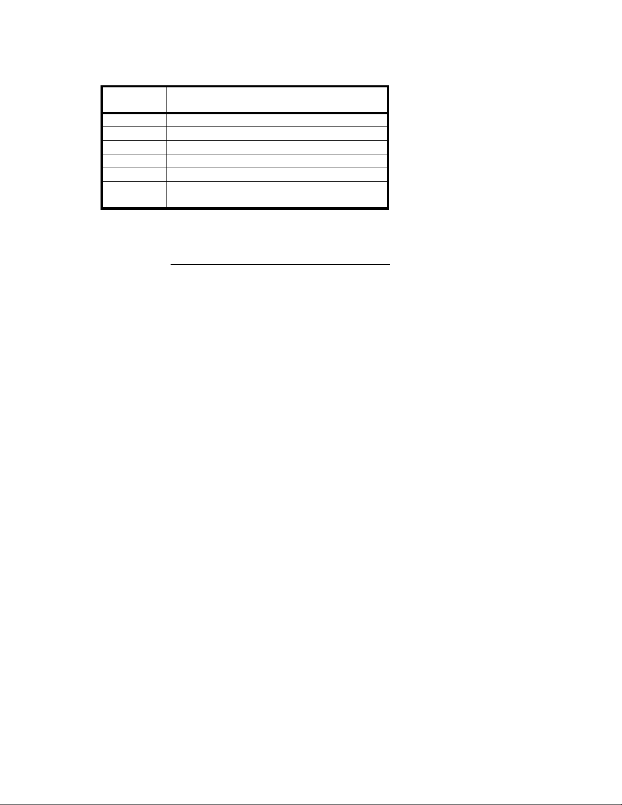
FACTORY SETTING
SP MODE
NUMBER
41 0 1 2 3 4 5 6 7 8 9 10 11 12 13 14 15
42 0 1 2 3 4 5 6 7 8 9 10 11 12 13 14 15
43 0 1 2 3 4 5 6 7 8 9 10 11 12 13 14 15
44 0 1 2 3 4 5 6 7 8 9 10 11 12 13 14 15
47 0 1 2 3 4 5 6 7 8 9 10 11 12 13 14
48 128 129 130 131 132 133 134 135 136
137 138 139 140 [ ]
FACTORY SETTING DATA
SERIAL No.
Page 2
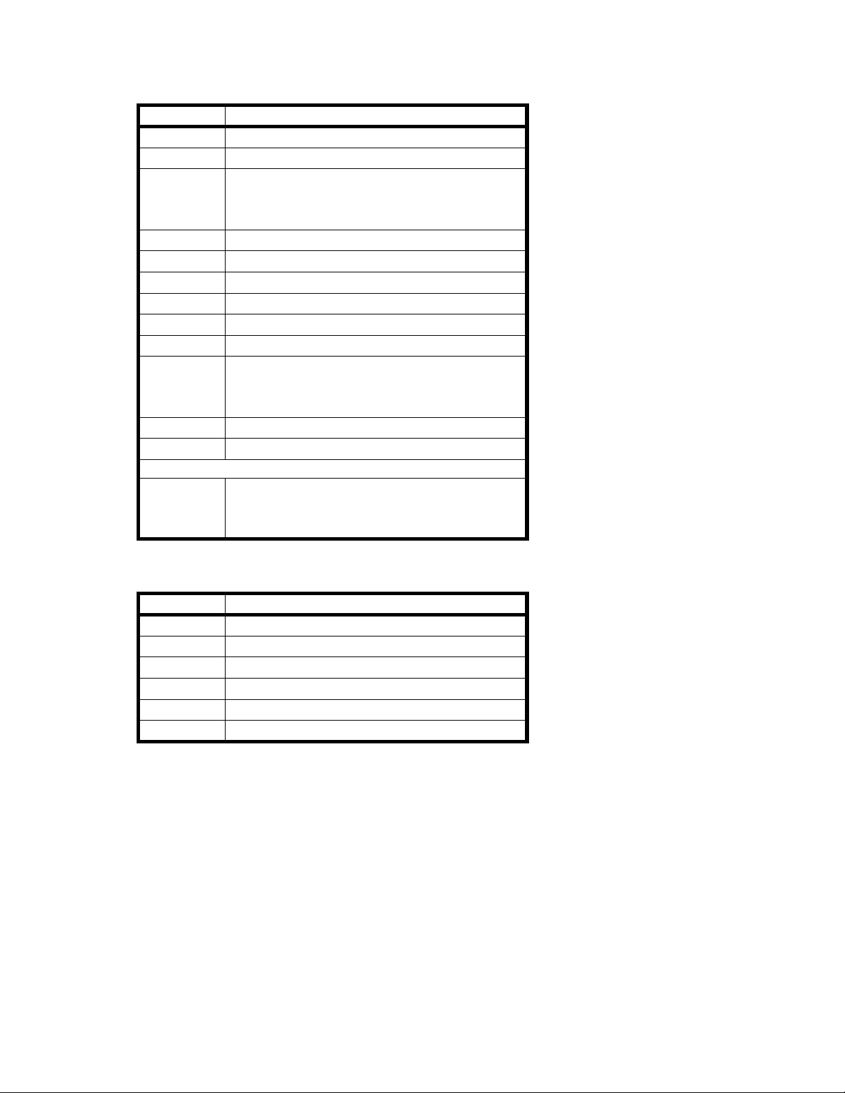
TEST POINTS
Copier Main Board
NUMBER FUNCTION
TP101 GND
TP102 VCC (+5V)
TP103 ADS (Auto Image Density Sensor)
Adjust the voltage to 2.5 ± 0.1 using
VR101.)
TP104 GND
TP105 AVSS (GND)
TP106 GND
TP107 HT (23oC 96kΩ)
TP108 BIN (Development Bias Fee d Ba ck)
TP109 GIN (Grid Voltage Feed Back)
TP110 PSE (ID sensor voltage)
Adjust the voltage to 4.0 ± 0.2 using
VR102.
TP111 EXPO (Exposure Lamp Voltage)
TP112 GND
JP103 Key Counter (Cut this jumper wire when
installing the key count er on the
machine.)
DF Main Board
NUMBER FUNCTION
TP102 +5V
TP103 GND
TP104 Factory Use
TP105 +12V
TP106 +24V
TP107 Factory Use
Page 3
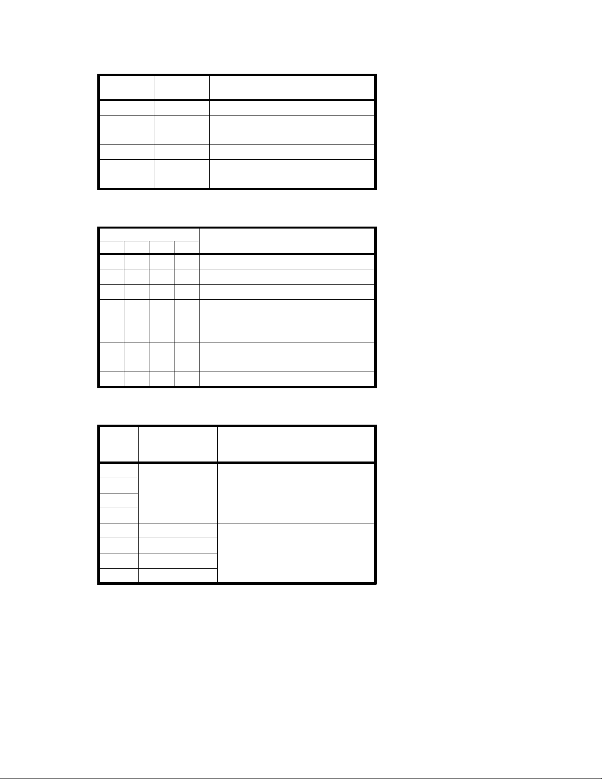
DIP SWITCHES
Copier Main Board
DIP
SWITCH
NORMAL FUNCTION
101-1 OFF Free Run
101-2 OFF Forced Start (Ready temp .
by-passed) Factory Use
101-3 OFF Clear Counter and/or memory
101-4 OFF Service Program modes
access
DF Main Board
DIP SWITCH 101 FUNCTION
1234
ON OFF OFF OFF
ON OFF OFF ON
OFF ON OFF ON
OFF OFF ON ON
Normal
1 sided free run
2 sided free run
Solenoid test:
Switch101 - solenoids ON
Switch102 - solenoids OFF
ON ON OFF ON
Motor test (lift switch must be
ON.)
ON ON ON ON
All indicators ON
Duplex Main Board
DIP
SWITCH
FACTORY
SETTING
FUNCTION
700-1 Jogger Position Adjustment
700-2
700-3
(0.5mm per step)
Refer to the Data Table.
700-4
700-5 OFF
700-6 OFF
Factory Use
700-7 OFF
700-8 OFF
Page 4

Data Table
DIP SWITCH 700 (0:OFF, 1:ON) ADJUSTMENT VALUE
1234
0000 -3.5mm
1000 -3.0mm
0100 -2.5mm
1100 -2.0mm
0010 -1.5mm
1010 -1.0mm
0110 -0.5mm
1110
0001 0.5mm
1001 1.0mm
0101 1.5mm
1101 2.0mm
0011 2.5mm
1011 3.0mm
0111 3.5mm
1111 4.0mm
±0
Page 5

VARIABLE RESISTORS
Copier Main Board
NUMBER FUNCTION
VR101 Adjusts ADS Voltage (2.5 ± 0.1)
VR102 Adjusts ID Sensor Voltage (4.0 ± 0.2)
Power Pack (CC/Grid/Bias)
NUMBER FUNCTION
VRC Adjusts Main Charge Current
VRG Adjusts Standard Grid Voltage
VRB Adjusts Standard Dev. Bias
(Factory Use)
Power Pack (T&S)
NUMBER FUNCTION
VRT Adjusts Transfer Current
VRD Adjusts Separation Current
AC Drive Board
NUMBER FUNCTION
VR401 Factory Use
DF Main Board
NUMBER FUNCTION
VR101 Factory Use
VR102 Original leading edge registration
adjustment (One sided orig ina l mo de)
VR103 Original leading edge registration
adjustment (Two sided origina l mode )
VR106 Factory Use
Page 6

SP MODE OVERVIEW
SP Mode Data When
Movement Check
5 Exposure Lamp OFF - EM
6 Jam Detection OFF - EM
8 Input Check (Refer to Sensor/Switch Data Check Table) EM
9 Output Check (Refer to Electrical Component Check Table) EM
Installation and/or Sales Demonstration
10 Color Developer Initial Setting - Replace-
11 All Indicators ON - 12 220V/240V Conversion 0: 220V
1: 240V
User Requests
15 Auto Reset Time 0: 1 min.
1: 3 min.
2: None
16 Count Up/Down 0: Up
1: Down
17 Auto Feed Station Shift 0: Auto Shift
1: Manual
19 ADS Priority 0: ADS
1: Manual
20 APS Priority (When turning on the main
switch) (A054 copier only)
21 APS Priority (When the original is set on the
DF)
22 SADF Shut-off Time 0: 5 sec.
23 ADF Free Size 0: No 1: Yes 24 Factory Used
25 Margin Adjustment in Duplex Mode 0: Yes 1: No 27 A3 (DLT) Double Counter 0: Normal
28 Sort Priority 0: Manual
29 Fusing Temperature Control 0: ON/OFF
Copy Quality Check and/or Adjustment
30 Black Toner Supply Mode 0: Detect Mode
31 Black Toner Supply Ratio (Detect Mode) 0: 15% 1: 7%
32 Black Toner Supply Ratio (Fixed Mode) 0: 7.0% 1 3.5%
0: APS
1: Manual
0: APS
1: Manual
1: 60 sec.
1: Double
1: Auto Sort
1: Phase
1: Fixed Mode
2: 30% 3: 60%
2:10.5% 3: 14.0%
Performed
ment
Installation
-
-
-
-
-
-
-
-
-
EM or PM
EM or PM
EM or PM
Page 7

SP Mode Data When
33 ID Sensor Bias (Black) 0:-260V 1:-220V
2:-280V 3:-300V
Performed
EM or PM
34 ADS Level 0: Normal
1: Darker
2: Lighter
35 Black Toner ID Detection 0: 10 copies
1: 5 copies
37 Black Bias Adjustment 0: Normal
1: Darkest
2: Darker
3: Lighter
4: Lightest
41 Lead Edge Erase Margin Adjustment 0 – 15 EM
42 Registration Adjustment 0 – 15
43 Vertical Magnification Adjustment 0 – 15
44 Horizontal Magnification Adjustment 0 – 15
47 Focus Adjustment 0 – 15
48 Light Intensity Adjustment 100 – 150 EM and PM
49 Fusing Temperature Adjustment
51 Exposure Lamp Voltage Display - 52 Fusing Temperature Display - 54 Vsg Adjustment (VR102 on the main board)
55 Vsg & Vsp Check - 56 ADS Voltage Adjustment
(VR101 on the main board)
59 Bias Voltage Check - 61 Drum Wear Compensation Setting 0: 1/10h
62 ID Sensor Grid Voltage Setting Factory Use (The
63 Toner Supply Unit Initial Setting - Installation
64 Black Toner Density Level Display 0 – 4 65 Black Developer Initial Setting - Replace66 Drum Initial Setting 67 Vr Correction Ratio - 68 Vr Forced Detection - 69 OPC Counter - -
Options and Others
70 Color Toner Supply Ratio (Fixed Mode) 0: 14% 1: 7%
71 Sorter Operation 0: No
73 Color Copy Counter - EM or PM
175°C – 190°C
4.0 ± 0.2 V
2.5 ± 0.1 V
1: 1/20h
data must be "7")
2: 21% 3: 28%
1: Sorter (1)
2: Sorter (2)
EM or PM
EM
EM and PM
EM and PM
-
-
ment
EM or PM
Installation
Page 8

SP Mode Data When
Performed
74 Color Toner ID Detection 0: 5 copies
1: 10 copies
75 ID Sensor Bias (Color) 0: Normal
1: Lighter
2: Darker
3: Darkest
76 Sorter Bin Capacity 0: No Limit
1: Limit
77 ADF Odd Number Originals (Duplex Mode) 0: ON
1: OFF
79 Color Bias Adjustment 0: Normal
1: Darkest
2: Darker
3: Lighter
4: Lightest
80 Red Toner Density Level Display - EM
81 Green Toner Density Level Display 82 Blue Toner Density Level Display 87 PM Interval Setting 0: No PM
1: 40K
2: 60K
3: 80K
4: 100K
88 PM Counter Display - 89 PM Counter Reset - 93 Maximum Copy Quantity 1 – 99 User
Clear Mode
98 Clear Counters 0: No 1: Yes 99 Clear All Memory 0: No 1: Yes -
Copy and Original Counters
100 First Station Copies - EM or PM
101 1st Paper Tray Copies 102 2nd Paper Tray Copies (A054 copier only)
105 Duplex Copies 106 DF Originals -
Service Call Counters
120 Service Calls (Total) 121 Optics Section Service Calls 122 Exposure Lamp Service Calls 123 Not Used
124 Fusing Section Service Calls - EM
125 Service Calls for Interface Communication -
Misfeed Counters
130 Misfeeds (Total) 131 Number of Misfeeds by Location
1: Paper Feed 2: Exit 3: Sorter 4: DF 5: Duplex
EM
EM or PM
EM
User
Request
EM or PM
-
Request
EM
EM
Page 9

SERVICE CALL AND USER CODE TABLE
SERVICE CALL CODE
E-CODE CONTENTS SP Mode No.
(SC Counter)
11 Exposure Lamp Error
The feed back signal beomes higher than 4.2 volts (r.m.s)
for 1.0 second when the exposure lamp is on, or it
becomes higher than 1.0 volt (r.m.s) for 1.0 second when
the exposure lamp is off.
12 Exposure Lamp Error
The feed back signal falls below 0.5 volt (r.m.s) for 1.0
second when the exposure lamp is on, or the exposure
lamp stays on for longer than 10 seconds.
13 Zero Cross Signal Error
The CPU does not receive the zero cross signal within
0.56 second.
21 Scanner Home Position Error
The scanner home position sensor remains off (LOW) 8
seconds after the main switch is turned on.
22 Scanner Home Position Error
The scanner home position sensor still on (HIGH) 1.0
second after the scanner starts.
28 Lens Home Position Error
The lens home position sensor remains off (LOW) 3.5
seconds after the lens move to the home position.
29 Lens Home Position Error
The lens home position sensor is still on (HIGH) 3.5
seconds after the lens leaves the home position.
2A 4th/5th Mirror Home Position Error
The 4th/5th mirror home position sensor is still on (HIGH)
2.5 seconds after the 4th/5th mirror assembly moves to
the home position.
2B 4th/5th Mirror Home Position Error
The 4th/5th mirror home position sensor is still off (LOW)
2.5 seconds after the 4th/5th mirror assembly leaves the
home position.
52 Fusing Warm-up Error
The temperature detected by the thermistor does not
o
reach 175
C within 100 seconds after the main switch is
turned on.
53 Fusing Overheat
The temperature detected by the thermistor becomes
o
higher than 240
C.
55 Fusing Thermistor Open
The temperature detected by the thermistor does not
reach 2
o
C within 30 seconds after the main switch is
turned on.
SP Mode #122
(Exposure
Lamp)
SP Mode #121
(Optics)
SP Mode #124
(Fusing
Section)
Refer to
NOTE b)
–
Page 10

E-CODE CONTENTS SP Mode No.
(SC Counter)
70 Toner Overflow Sensor ON
When the toner overflow sensor is on, "E70" blinks in the
magnification indicator. Up to 250 copies additional can
be made. After 250 copies are made, "E70" lights and
copies cannot be made.
80 Duplex and Copier Main Board Communication Error
The copier main board does not receive any signal from
the duplex main board.
81 Interface Board Error
The interface board is not connected when the duplex
unit is installed.
82 Jogger Home Position Error
The output of the jogger home position sensor remains
LOW as the duplex main board is driving the jogger
fences outward.
83 Jogger Home Position Error
The output of the jogger home position sensor remains
HIGH as the duplex main board is driving the jogger
fences inward.
SP Mode #125
(Interface
Comunication)
–
NOTE: a) E-codes (E1 to E8) are displayed in the copy counter. To display the two digits,
press the Enter key.
Example:
When the machine detects the E11 condition, E1 is displayed in the copy
countrer. Hold down the Enter key, and "11" is displayed in the copy counter.
b) When the service call (E5) conditions occur, for safety reason they cannot be
cleared by turning off/on the main switch. The following procedure must be
performed to clear these service call conditions:
1. Turn on the main switch.
2. Turn DIP switch 101-1 on and off.
3. Turn the main switch off and on.
USER CODE
U-CODE CONTENTS
1 Right Cover Open
2 Key Counter Not Set
3 Development Unit Not Set
4 Sorter Open
5 Cassette Lift Sensor Not ON (Cassette is not properly set.)
 Loading...