

Page 1

INTRODUCTION
The A085/A087/A08 8 cop ier is based on the A069/A073/A07 4 cop ier, the base
copier.
This documentation gathe rs the modif ications to the base copier’s service manual
that service personnel will need to service this cop ier. This package contains the
following:
° A table of contents for the modified manual
° A list of the major difference s between this copier and the base
copier
° A set of selected pages to replace th e ones in th e base copier’s
manual, including revised specifica tions SP mode tables.
° An explanation of this mode l’s new fu nct ions
° An explanation of DF’s (A497) new f unction
° A section for the new sorter sta ple r (A 374)
Page 2

IMPORTANT SAFETY NOTICES
PREVENTION OF PHYSICAL INJURY
1. Before disassembling or assembling parts of the copier and peripherals,
make sure that the copier power cord is unplugged.
2. The wall outlet should be near the copier and easily accessib le.
3. Note that some components of the copier and the paper tray unit are
supplied with electrical voltag e even if the main switch is turned off.
4. If any adjustment or operation check has to be made with exterior covers
off or open while the main switch is turned on, keep hands away from
electrified or mechanically driven components.
5. If the hot roller temperature is low when the main switch is turned on, the
copier starts idling automatically when the warm-up period is completed.
Keep hands away from the mechanical and the electrical components to
avoid any injury.
6. If the start key is pressed before the copier completes the warm-up
period (Ready indicator starts blinking), keep hands away from the
mechanical and the electrical components as the copier starts making
copies as soon as the warm-up period is completed.
7. The inside and the metal parts of the fusing unit beco me extremely hot
while the copier is operating. Be careful to avoid touching those
components with your bare hands.
HEALTH SAFETY CONDITIONS
1. Never operate the copier without the ozone filters installed.
2. Always replace the ozone filters with the specified ones at the specified
intervals.
3. Toner and developer are non-toxic, b ut if you get either of them in your
eyes by accident, it may cause temporary eye discomfort. Try to remove
with eye drops or flush with water as first aid. If unsuccessful, get medical
attention.
Page 3

OBSERVANCE OF ELECTRICAL SAFETY STANDARDS
1. The copier and its peripherals must be installed and maintained by a
customer service representative who has completed the training co urse
on those models.
2. The RAM board on the main control board has a lithium battery which
can explode if replaced incorrect ly. Replace the battery only with an
identical one. The manufacturer recommends replacing the entire RAM
board. Do not recharge or burn this battery. Used batteries must be
handled in accordance with local regulations.
SAFETY AND ECOLOGICAL NOTES FOR DISPOSAL
1. Do not incinerate the toner cartridge or the used toner. Toner dust may
ignite suddenly when exposed to open flame.
2. Dispose of used toner, developer, and organic photoconductor
according to local regulations. (These are non-toxic supplies.)
3. Dispose of replaced parts in accordance with local regulations.
4. When keep ing used lithium batteries in order to dispose of them later, do
not put more than 100 batteries per sealed box. Storing larger numbers
or not sealing them apart may lead to chemic al reactions and heat
build-up.
Page 4

SECTION 1
OVERALL MACHINE
INFORMATION
Page 5
10 July 1992 MAJOR DIFFER ENT POINTS FROM THE BASE COPIER : A069/A073/A074
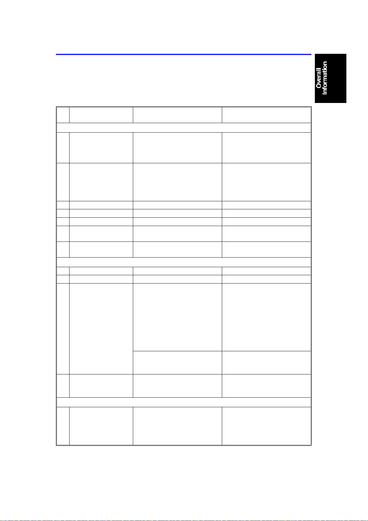
1. MAJOR DIFFERENT POINTS FROM THE
BASE COPIER : A069/A073/A074
The major different points of this copier A085/A087/A088 fr om the base
cop ier A069/A073/A074 are listed in the fo llowin g table:
No. Section/Item This model (A085/A087/A088) Base model
(A069/A073/A074)
Major features
1 Copy speed 27 copies/min.
(A4/11 x "8
16 copies/min. (A3)
15 copies/min. (11" x 17")
2 First copy time 5.4 seconds
for type 1 & 3: upper tray
5.8 seconds
for type 2: LCT
(A4/11" x 8
3 Color copy Not applicable Opti on
4 Overlay mode Not applicable Standard for A074
5 Edit function Not applicable Option for A 074
6 Shadows from
pasted originals
7 Combine 2 originals
mode
Erased for normal thickness
paper
Standard with ARDF Not applicable
1/2" sideways )
1/2" sideways )
Operation panel
8 Guidance display Not applicable Standard for A074
9 Beeper Not applicable Standard
10 Indicators (LEDs) The following indicators are not
applicable:
Color copy, full size, overlay,
ten keys zoom, enlarge,
reduce, special features, editor
boar d guidance , area memory ,
use d toner tank, close cover,
set key co unter , call service,
zoom, start key (red/ green)
The f ollowing indicator has
been newly added:
Combine 2 originals
11 Keys The following keys are not
applicable:
Col or copy, ten keys zoom
Optics
12 1st scanne r Newly designed
(The newly designed main
reflector lets shadows be
erased when copying pasted
originals.)
33 copies/min.
(A4 / 11"X8
19 copies/min. (A3)
18 copies/min. (11" x 17")
4.5 seconds
for type 1 & 3: upper tray
4.9 seconds
for type 2: LCT
(A4/11" x 8
Not erased
Standard
(Ove rlay/area memory; A074
only, editor board guidance;
option)
Not applicable
Standard
Original
1/2" sideways )
1/2" sideways )
1-1
Page 6
MAJOR DIFFERENT POINTS FROM THE BASE COPIER : A069/A073/A074 10 July 1992
No. Section/Item This model (A085/A087/A088) Base model
(A069/A073/A074)
Development
13 Development unit
shift mechanism
Not applicable Standard
Around the drum
14 Automatic drum
current adjustment
Not applicable Standard
Paper Feed
15 Tray lock Solenoid
(not for duple x tr ay)
Not applicable Standard
Fusing
16 Fusing unit Newly designed
(Serviceability has been
improved. The fusing roller
pressure a nd the nip band
width are less.)
17 Pressure roller Newly designed
(The diameter at the middle is
slightly smaller than that at the
ends, reducing the occurrence
ratio of creasing afte r f us ing.)
Original
Original (common with A006)
Process control
18 Process speed 150 mm/sec.
(The ma in motor speed is the
same, but its output is slowed
down by a step-down pulley.)
19 Grid bias voltage Vgi (for image): -715 V
V gp (for sensor pattern): -480 V
20 Separation corona
current
G correction Applies another -2 0 V to the
21 V
22 Exposure lamp
voltage
23 Color toner density
control
24 Development bias
voltage control for
color toner
ac 190 µA ac 210 µA
grid bias voltage after the drum
has rotated 2, 44, 75, and 105
hours.
The target lamp voltage for the
first copy of a copy run is
decreased by –0 .5 V.
Not applicable Standard
Not applicable Standard
180 mm/sec.
Vgi (for image): -745 V
V gp (for sensor pattern): -500 V
Applies another -20 V to the
grid bias voltage after the drum
has rotated 2, 37, 63, and 88
hours.
The target lamp voltage for all
the copies of a copy run are
the s ame.
Pe ripheral equipment
25 Color development
unit
26 Edit erase lamp unit
(Editing interface
adapter type B)
27 Editor board Not applicable Option for A074
Not applicable Option
Not applicable Option
1-2
Page 7

10 July 1992 MAJOR DIFFER ENT POINTS FROM THE BASE COPIER : A069/A073/A074
No. Section/Item This model (A085/A087/A088) Base model
(A069/A073/A074)
28 Sorter stapler (A366;
fixed bin type)
29 Sorter stapler (A374;
moving bin type)
30 Auto reverse
document feeder
(A497)
Not applicable Option
Option Not applicable
Option with combine 2
origi nals mode
(The software has been
changed. The ARDF with the
new ROM has a different
destination code.
The ARDF can be also installed
on other current models
(A069/A073/A074/A053).)
Option
1-3
Page 8

SPECIFICATIONS 10 July 1992
2. SPECIFICATIONS
Configuration: Desktop
Copy Process: Dry electrostatic transfer system
Originals: Sheet/Book
Original Size: Maximum A3/11" x 17"
Copy Paper Size: Maximum A3/11" x 17"
Minimum B5/11" x 81/2" - Paper tray
A6/51/2" x 8 1/2"(lengthwise)
-By-pass feed table
(LCT B5/A4/11" x 81/2" sideways only)
(Duplex Copying)
Multiple:
Single:
A4 and B5/81/2" x 11" (sideways)
Maximum A3/ 11" x 17"
Minimum B5/8" x 13"
Copy Paper Weight: • 250-sheet paper tray and 1000-s heet large
capacity tray:
52 –128g/m2, 14 –34lb
• By-pass feed table:
52 –157g/m2, 14 –42lb
• Duplex:
64 –105 g/m2, 17 –28lb
Reproduction Ratios: 4 Enlargement and 6 Reduction
A4/A3 Version LT/LDG Version
200%
Enlargement
Full S iz e 100% 100%
Reduction
141%
122%
115%
93%
82%
75%
71%
65%
50%
200%
155%
129%
121%
93%
85%
77%
74%
65%
50%
Receiving Tray
Capacity:
250 sheets (B4/81/2" x 14" and smaller)
100 sheets (A3/ 11" x 17")
1-4
Page 9
10 July 1992 SPECIFICATIONS
Power Source: 115V, 60HZ, more than 12A (for N.A)
110V, 60HZ, (for Taiwan)
220/230/240V, 50HZ/60HZ, more than 8A
(for EU and AA)
Power Consumption: Maximum: 1.5 KW
Warm-up: 0.77 KW
Stand -by : 0.14 KW
Co py Cycle (average): 1.2 KW
Noise Emission: Stan d-by: less than 40 dB
Copy Cycle (average):
less than 56 dB (copier only)
less than 59 dB (full system)
Maximum:
less than 62 dB (copier only)
less than 65 dB (full system)
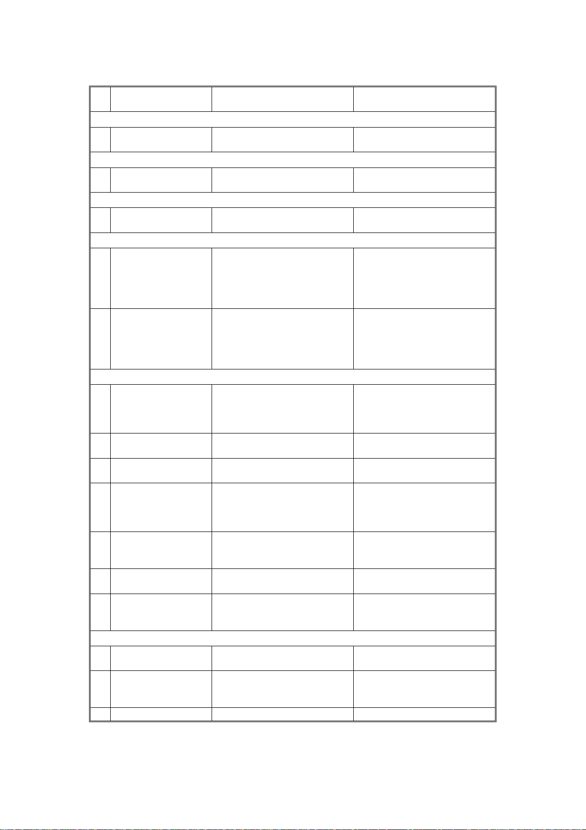
Dimensions:
Width Depth Height
Type 1
Type 2
Type 3
697 mm (1035 mm)
27.4" (40.7")
871 mm (1075 mm)
34.3" (42.2")
871 mm (1075 mm)
34.3" (42.2")
600 mm
23.6"
600 mm
23.6"
600 mm
23.6"
542 mm (574 mm)
21.3" (22.6")
542 mm (574 mm)
21.3" (22.6")
542 mm (574 mm)
21.3" (22.6")
( ): When the by-pass feed table is opened, the copy tray is extended, and
the platen cover is installed.
Weight: Copier only (Without the optional platen
cover= Approximately 2 kg (4.4 lb))
Type 1: approximately 77 kg (169.4 lb)
Type 2: approximately 87 kg (191.4 lb)
Type 3: approximately 83 kg (182.6 lb)
Zoom: From 50% to 200% in 1% steps
Copying Speed: 27 copies/minute (A4/81/2" x 11" sideways)
16 copies/minute (A3)
15 copies/minute ("11 x 17")
Copying Speed
with ARDF:
(Single copy (1 to 1),
27 copies/minute (A4/81/2" x 11" sideways)
16 copies/minute (A3)
15 copies/minute ("11 x 17")
full size)
Warm-up Time: Less than 110 seconds (20°C)
1-5
Page 10

SPECIFICATIONS 10 July 1992
First Copy Time: 5.4 seconds (A4/81/2" x 11" sideways)
Type 1, 3: (Upper tray feed)
5.8 seco nd s
Type 2: (Large capacity tray feed)
Copy Number Input: Ten keys, 1 to 999 (count up or count down)
manual Image Density
7 steps
Selection:
Automatic Reset: 1 minute standard setting; can also be set to 3
minutes or no auto reset.
Copy Paper Capacity: • By-pass feed table; appr oximately 20 sheets
• Paper tray: app roximately 250 sheets
• Large capacity tray; approximately 1000 sheets
Toner Replenishment: Black: cartridge exchange
(320 g/cartridge)
Optional Equipment: • Platen cover
• Document feeder
• Paper tray unit with one paper tray
• Paper tray unit with three paper trays
• 10 bin micro sorter
• 20 bin mini sorter
• 20 bin mid i sorter
• 20 bin sorter stapler
• Sorter adapter (needed when installing the
mini or midi sorter, or the sorter stapler)
• Interface PCB (needed when installing the
sorter stapler or the menu reader)
• Key counter
• Menu reader ( except for Europe)
• A3 counter (service part)
1-6
Page 11
(A328)
(A326)
10 July 1992 MACHINE CONFIGURA TION
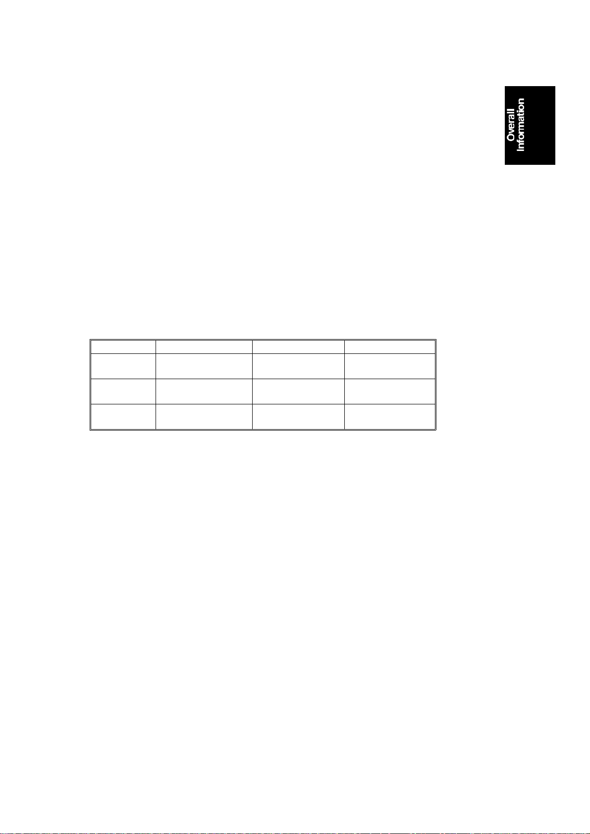
3. MACHINE CONFIGURATION
3.1 COPIER
TYPE 1 (A085) TYPE 2 (A088) TYPE 3 (A087)
UPPER TRAY 250 DUPLEX 250
LOWER TRAY 250 250 250
LCT – 1,000 1,000
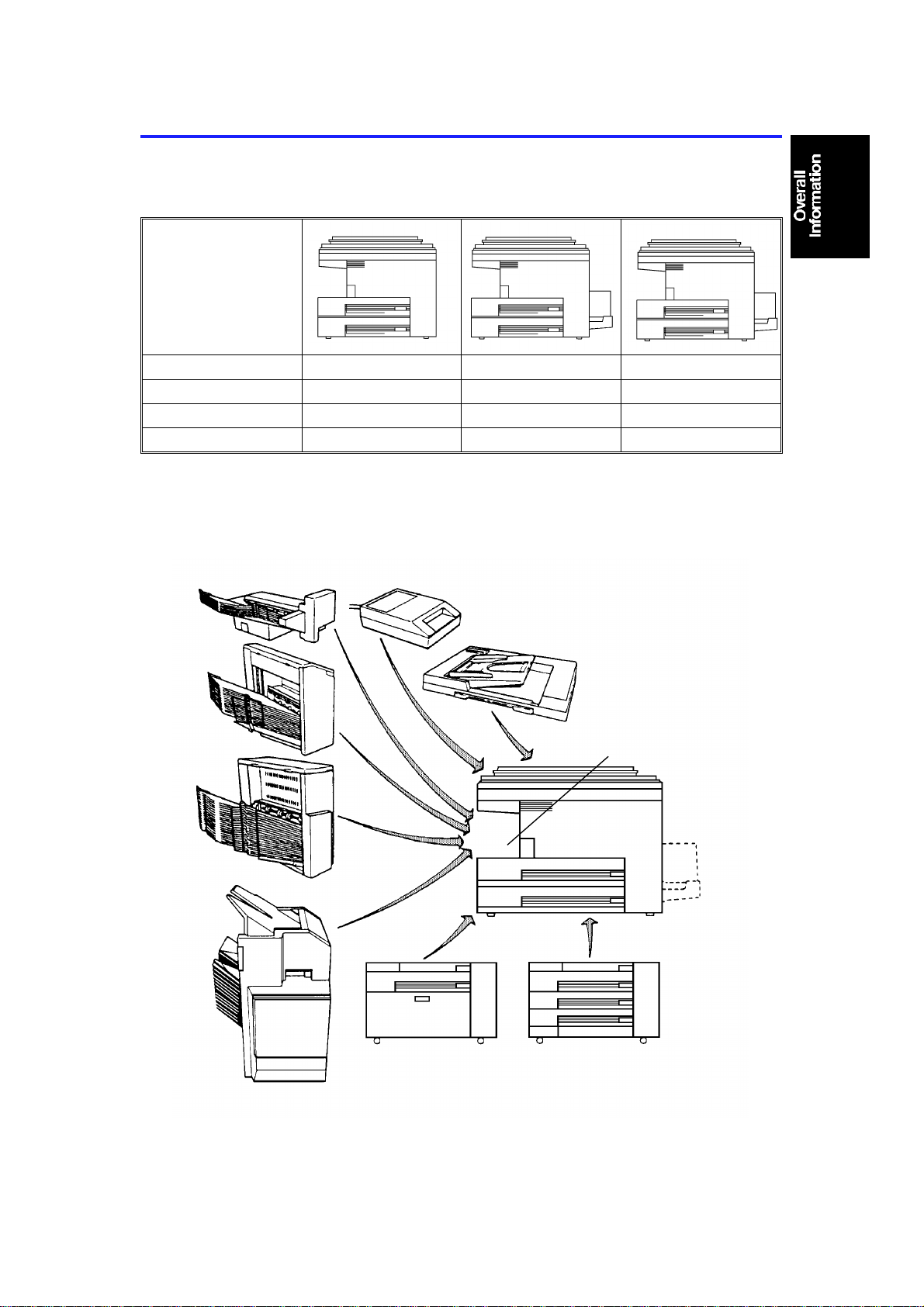
3.2 OPTIONAL EQUIPMENT
10BIN SORTER (A327)
20BIN SORTER
(A423)
20BIN SORTER
(A411)
MENU READER (A952)
ARDF (A497)
SORTER ADAPTER
SORTER ST APLER
(A374)
PAPER TRAY UNIT
(A325)
1-7
PAPER TRAY UNIT
Page 12
MACHINE CONFIGURATI ON 10 July 1992
REQUIRED
COPIER
TYPE 1
(A085)
1 TRAY
PAPER
TRAY UNIT
SORTER
DOCUMENT
FEEDER
MENU READER (A952) o o o **
(A325)
3 TRAY
(A326)
10 BIN
(A327)
20 BI N MINI
(A423)
20 BIN MIDI
(A411)
20 BIN
STAPLER
(A374)
ARDF (A497) o o o
TYPE 2
(A088)
ooo
ooo
ooo
ooo *
ooo *
ooo * **
TYPE3
(A087)
OPTIONAL
EQUIPMENT
SORTER
ADAPTER
(A328)
INTERFACE
PCB
(A344)
NOTE: * The sorter adapter is required to install the 20 bin
mini sorter, 20 bin midi sorter or sorter stapler .
* * The I/F board is required to install the sorter stapler
or Menu Reader.
1-8
Page 13

SECTION 2
DETAILED SECTION
DESCRIPTION
Page 14
[Fig. 2]
10 July 1992 OPTICS
1. OPTIC S
1.1 FIRST SCANNER
[C]
[B]
[Fig. 1]
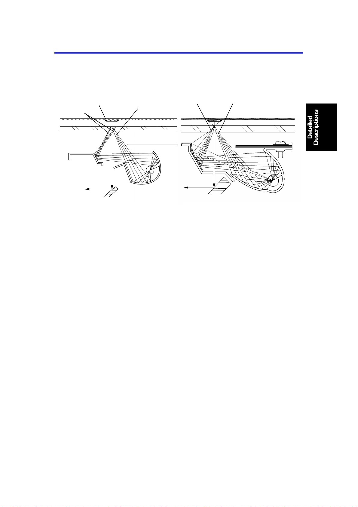
The first scanner of this copier has been re-designed from the one for the
base model (A069/A073/A074) to reduce shadows of p asted originals.
Although the exposure lamp’s rating voltage is the same, the shape of the
reflectors have been changed, as shown above. Figure 1 is fo r the base
model, and figure 2 is for this copier.
[A]
[B]
[A]
For figure 1, the light intensity [A] reflected from the main reflector is stronger
than the light intensity [B] reflected from the sub reflector. The proportion is
about 65% to 35%. Under this condition, as the scanner moves under the
original, the lead edge shadow [C] of the pasted parts of an original might
appear on copies.
For figure 2, the proportion of the light intensity [A,B] reflected from the main
and sub reflectors is almost 50% to 50%. Under this condition, both the lead
and trail edges of the pasted parts of an original will not make shadows.
Shadows might appear not only at the lead edge, but also the inner side of
the pasted parts. The light intensity of the exposure lamp at both ends is
slig htly stronge r than that at the center. This is nece ssary to have even
exposure on the drum surface through the lens. Because of this, eliminating
the side edge shadow of pasted parts of an original is very difficult. Although
the light intensity dis tribution of the expo sur e lamp from end to end has been
slightly changed on this model, the side edge shadow might appear on thick
pasted originals.
2-1
Page 15

SECTION 3
INSTALLATION
Page 16

10 July 1992 COPIER INSTALLATION
1. COPIER I NSTALLATION
1.1 ACCESSORY CHECK
1. Receiving Tray.......................................................................1
2. Outer Decal - Symbol Explanation .........................................1
3. Sorter Key Top and Cover.....................................................1
4. Counter Set Key (–17 machine only) .....................................1
5. Installation Procedure ............................................................1
6. Operating Instructions (Except –27 machine)........................1
7. New Equipment Condition Report
(–17, –19, –27, –29 machine only) ................................ 1
8. Envelope for NECR (–17 machine only).................................1
9. User Survey Card (–17 machine only)...................................1
10. Equipment Quality Report (–15 machine only).......................1
3-1
Page 17
[E]
COP I ER INS TALLATION 10 July 1992
1.2 INSTALLATION PROCEDURE
[A]
[A]
[A]
NOTE:
[B]
[D]
[C]
[A]
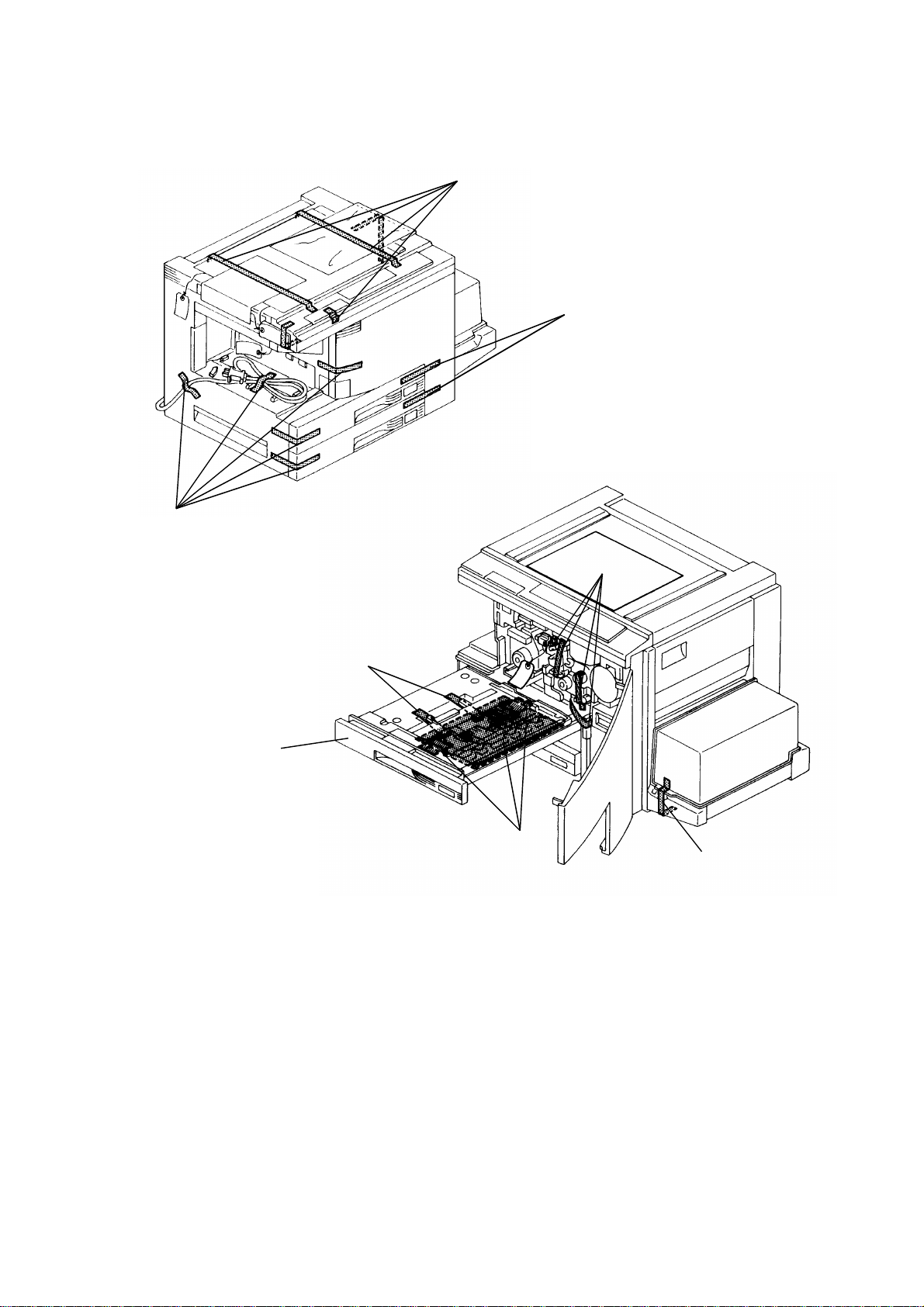
Keep the shipping retainers after installing the machine. They will
be reused if in the future the machine is transported to an
another location.
Proper reinstallation of the shipping retainers is required in order
to avoid any transport damage.
1. Remove the 12 strips of tape [A] as shown.
2. Open the front door and remove 4 strips of tape [B] as shown.
3. Pull out the duplex tray [C] and remove the 2 str ips of tape [D] and 3
sheets of paper [E] (duplex machine only).
3-2
Page 18
10 July 1992 COPIER INSTALLATION
[A]
[D]
[B]
[C]
[E]
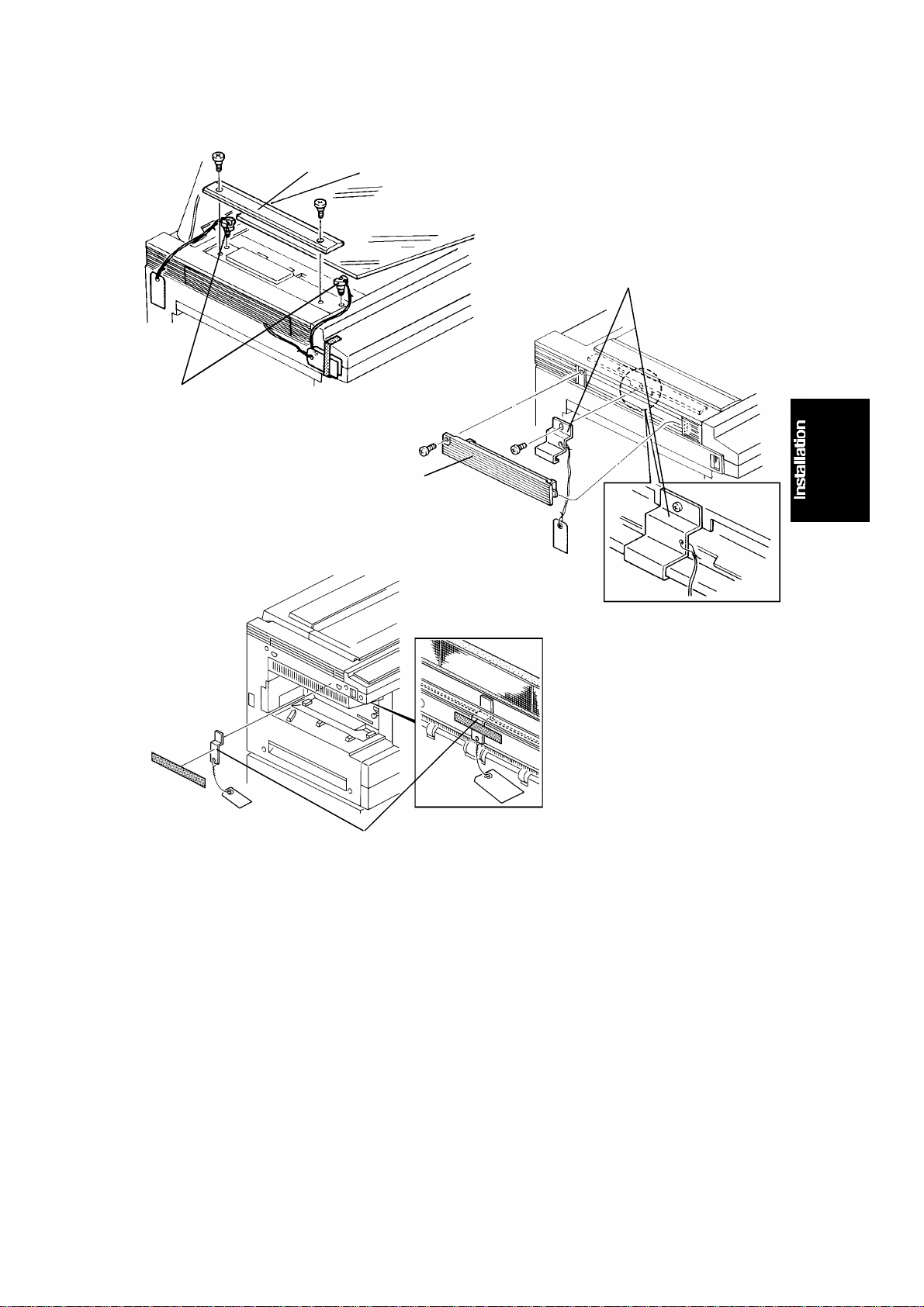
4. Remove the left scale [A] (2 shoulder screws).
5. Remove the scanner lock pin [B] simply by pulling it up from the front
and the r ear side of the left scale bracket .
6. Reinstall the left scale.
7. Remove the left optics cover [C] (1 screw).
8. Remove the scanner lock plate [D] (1 screw) and reinstall the left optics
cover.
9. Remove the ship ping retainer [E] ho lding the ozone filter. The retainer is
taped on the upper exit cover.
3-3
Page 19
[C]
COP I ER INS TALLATION 10 July 1992
[E]
[C]
[B]
[A]
[D]
[F]
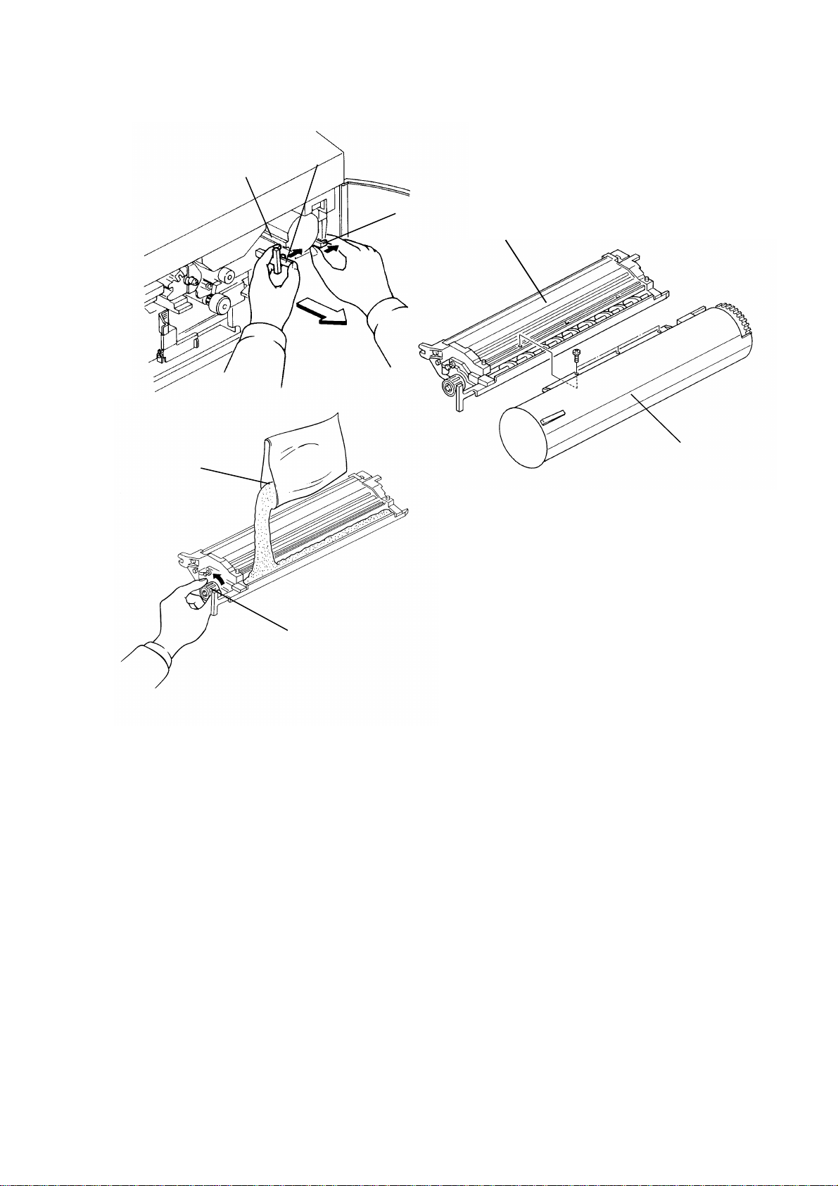
10. Push the development unit lock lever [A] to the right (to the lock
position).
11. Move the development release lever [B] to the right and pull out the black
development unit [C] half way. Holding the toner supply unit [D] with your
right hand and the bottom of the development unit with your left hand,
pull the unit all the way out . Place the unit on a clean sheet of paper.
12. Separate the toner supply unit from the development unit (3 screws).
13. Pour one pack of black developer [E] into the development unit while
turning the development roller knob [F] counterclockwise. This will
distribute the developer inside the unit.
14. Remount the toner supply unit on the development unit.
3-4
Page 20
10 July 1992 COPIER INSTALLATION
[B]
[C]
[A]
[D]
[E]
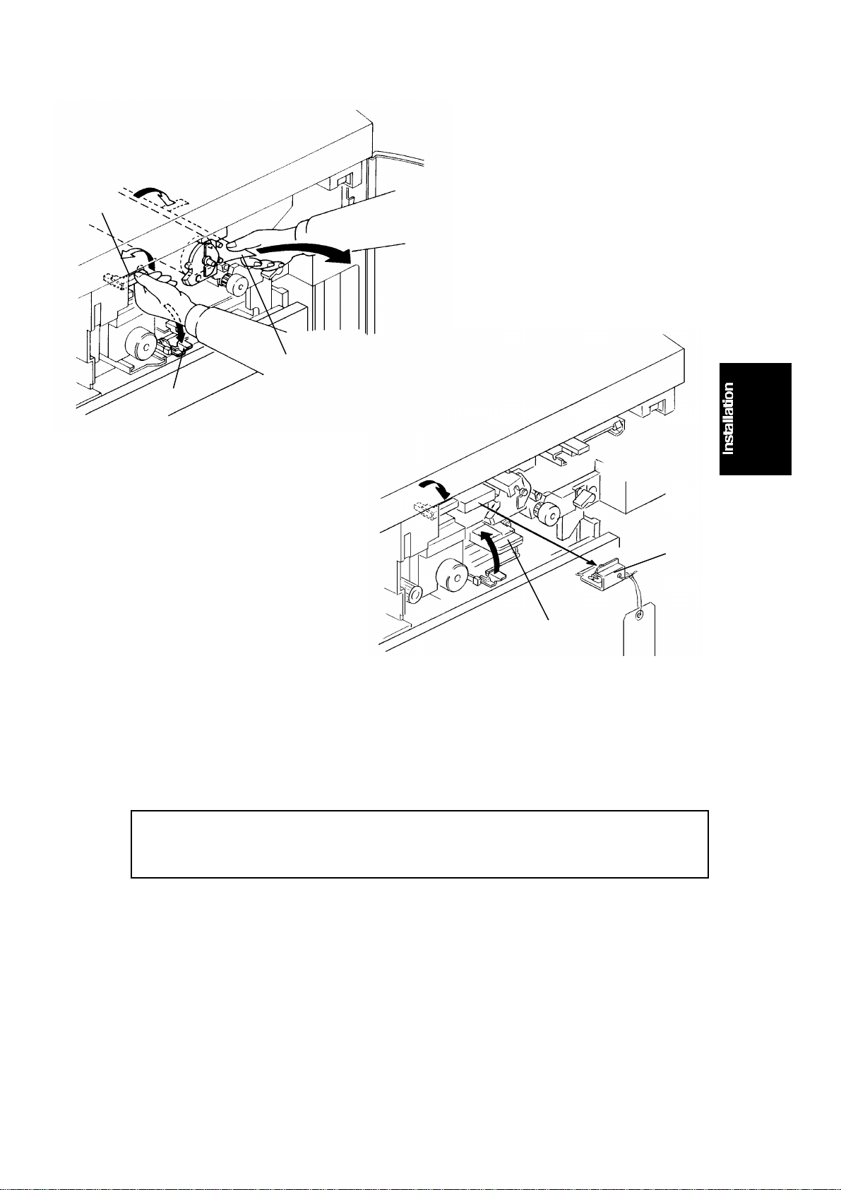
15. Lower the transfer & separation corona unit by pulling down the release
lever [A].
16. Turn the cleaning unit release lever [B] counterclockwise to the upright
posit ion . (Th e cleaning unit is released from the drum.)
17. Remove t he drum pr ot ective sheet [C] from the developm ent unit
opening.
CAUTION: To avoid damaging the pick-off pawls, remove the drum
protective sheet by pulling the lower side as shown in the
figure.
18. Turn the cleaning unit release lever clockwise to the set position.
19. Remove the clean ing blade lock plate [D].
20. Reset the transfer & separation corona unit [E].
3-5
Page 21

[D]
[E]
COP I ER INS TALLATION 10 July 1992
[B]
[C]
[C]
[A]
[F]
21. Install the black development unit [A] in the copier, and remove the cover
sheet [B] from the toner supply unit.
NOTE: • When installing the development unit, be sure that the
development unit rail is placed directly on the development
unit guide rail.
• Make sure that the development release lever [C] is in its
original p os ition after the development unit is set.
22. Shake the toner cartridge [D] well from side to side. While pushing the
toner cartridge in, insert it halfway into the holder with the seal [E] up.
23. As you peel off the seal, insert the cartridge completely. While pushing
the toner cartridge in, turn it counterclockwise until it stops.
24. Slide out the charge coron a unit [F] until it is fully extended and push it
back in to the o riginal position. Rep eat th is actio n several time s.
3-6
Page 22

10 July 1992 COPIER INSTALLATION
[B]
[D]
[F]
[E]
[C]
[A]
25. Close the front door and set the copy tray [A].
NOTE: The following steps from 26 to 29 are required only to install the
optional platen cover [B].
26. Remove the rear cover (remove 2 screws and loosen 2 screws).
27. Install the 2 shoulder screws [C] on the top cover as shown.
28. Pass the harness [D] throu gh the hole of the top cover and install the
optional platen cover (2 screws).
29. Couple the platen cover sensor connector [E] (3P white) with the copier
and reinstall the rear cover.
30. Stick the symbols explanation decal [F] on the top cover as shown. (If the
ARDF will be installed, stick the decal on the corresponding position of
the ARDF.)
31. If local voltage is 230 V or 240 V, perform t he vo ltage change procedure
(following the installation procedure).
3-7
Page 23
COP I ER INS TALLATION 10 July 1992
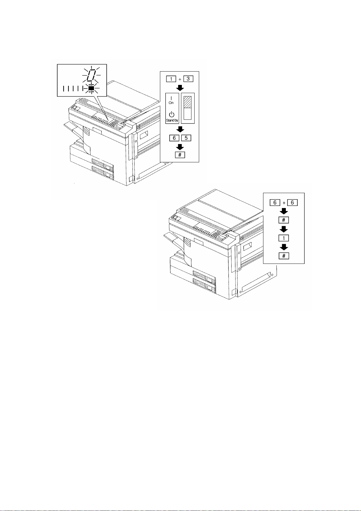
32. Load A3 ( 11" x 17") paper either in the 1st or the 2nd paper t ray and plug
in the machine.
33. While pressing both the "1" and "3" on the operation panel number keys,
turn on the main switch in order to access the SP mode.
NOTE: Release the number keys after confirming that the auto image
density indicator and the copy counter number "0" are blinking.
34. Enter "65" using the number keys and then press the enter key.
(The copier starts the black developer initialization, and this lasts about 5
minutes.)
35. Enter "66" using the number keys and press the enter key.
Press "1", then the enter key.
(The copier performs the drum initial setting.)
3-8
Page 24

10 July 1992 COPIER INSTALLATION
36. Enter "54" using the number keys and press the enter key, then the start
key.
(The copier performs ID/V sensor adjustments.)
37. Enter "48" using the number keys and then press the enter key twice.
38. Set the test chart on the exposure glass.
39. Make a full size copy at the manual image density level # 4 (center) aft er
the copier has warmed up.
3-9
Page 25

COP I ER INS TALLATION 10 July 1992
40. Confirm that level 2 of the gray scale is just visible on the copy.
If the image density is not correct, go thro u gh the following steps.
(1) Press the enter key twice.
(2) Change the exposure lamp voltage data displayed in the
magnification ratio indic ator. Use the number keys and follow these
rules:
If the image density is too dark: increase the setting
If the image density is too light: decrease the setting
NOTE: The dat a can be s et between 50 and 75 in 0.5 steps.
(3) Press the enter key and then make a copy.
(4) Confirm if the image density is correct or not.
If not, repeat the above steps from (1) to (3).
NOTE: The initial exposure lamp voltage must be adjusted in this step. If
the adjustment is done after step 43 (the machine performs the
initial VL pa ttern detection), th e reference volt age for the
exposure lamp voltage correction will be wrong throughout the
drum’s life.
3-10
Page 26

10 July 1992 COPIER INSTALLATION
41. Press the enter key and enter "56" using the number keys.
42. Press the enter key, then the start key.
(The copier performs the ADS sensor adjustment.)
43. Turn the main switch off and on.
44. Enter "6" using the number keys and make copies in the full s ize mode.
(The copier performs the VR sensor initial check during the copy cycle.
When the copy cycle is finished, the copier performs the VL sensor initial
check by lighting the expo sure lamp at the home position.)
45. Check the machine operation and copy quality.
46. Tell the customers that this copier sometimes keeps turning on the
exposure lamp at the home position when copy jobs are finished (the
same phenomenon as in step 44).
This is normal for this copier, and this also helps maintain good copy
quality.
3-11
Page 27

COP I ER INS TALLATION 10 July 1992
VOLTAGE CHANGE (220V to 230/240V)
[B]
[A]
[C]
NOTE: If the voltage of electrical power supp ly from wall outlets is 230V
or 240V, the following procedure must be done before plugging
in the machine.
CAUTION: Make sure that the power cord of the machine is
unplugged before starting the following procedure.
1. Remove the rear cover (remove 2 screws and loosen 2 screws).
2. Swing out the dc power supply board assembly [A] (1screw).
3. Disconnect the 1P connector [B] of the ac main harness and reconnect it
to the appropriate voltage connector [C] of the main tr ansformer.
NOTE: Each 1P connector of the main transformer has its vo ltage rating
printed on it.
4. Reassemble the copier.
3-12
Page 28

SECTION 4
SERVICE TABLES
Page 29

10 July 1992 SERVICE PROGRAM MODE
1. SERVICE PROGRAM MODE
1.1 MEMORY ALL CLEAR PROCEDURE (SP99)
CAUTION: Mem ory all clear mode (SP99) clears all the correction data
for process control and software counters, and returns all
the m odes to the default settings. Norma lly, this mode
should not be performed.
This procedure is required only when the copier
malfunctions due to a damaged RAM or when replacing the
RAM board for any reason.
1. Access the SP mode through Access Procedure 3. (While pressing both
the Clear Modes and Clear/Stop keys on the operation panel, turn on the
main switch.)
2. Enter "99" and press the Enter key.
3. Enter "1" and press the Enter key.
4. Enter the factory-set values in the following SP modes:
40: Jogger span (Duplex machine only)
41: Lead edge erase
42: Registration
43: Vertical magnification
44: Horizontal magnification
45: Duplex magnification (Duplex machine only)
47: Focus adjustment
50: Lens error correction
62: Grid reference voltage
161: Grid volt/M-CH(P)
162: T-CH PWM
163: D-CH (AC) PWM
164: D-CH (DC) PWM
NOTE: There is an SP data table sheet underneath the front upper cover
which gives the above factory -set values.
5. Turn off the main switch.
6. Clean the used toner tank because the toner end counter has been
cleared.
4-1
Page 30

SER VICE PROGRAM MOD E 1 0 July 1992
7. Replace the OPC drum with a new one.
NOTE: Sinc e the drum counter for the process control has been
cleared, the old drum cannot be used. If the old drum is used
after all memory is cleared, a dirty background and/or toner
scattering will appear on copies sooner or later because proper
VG correction will not be applied to the drum.
8. Clean the optics, sensors, and inside of the machine if necessary.
9. If the high voltage supply board - C TBG and/or - D is not the o riginal one,
do the following:
1) Clean the corona unit casings and replace the corona wires with new
ones.
2) Enter to the SP mode by the access procedure 2.
3) Enter the grid voltage correction data in SP62 referring to the label on
the high voltage supply board - CTBG.
4) Adjust the transfer corona current if the high voltage supply board CTBG is not the origin al one.
5) Adjust the separation coro na current if the high voltage supply board D is not the origin al one.
10. Enter the SP mode by access procedure 2. (While pressing both "1" and
"3" on the operation panel number keys, turn on the main switch)
11. Enable optional equipment operation by SP71 (sorter) and SP72 (paper
tray unit) as necessary.
12. Perform the following SP modes:
SP66: Drum initialize
SP54: Auto Vsg/Vlg adjustment
SP48: Exposure lamp voltage adjustment
SP56: Auto ADS gain adjustment
13. Check copy quality and the paper path and do the necessary
adjustments.
4-2
Page 31

10 July 1992 SERVICE PROGRAM MODE
1.2 SERVICE PROGRAM MODE TAB LE
NOTE: 1. A "p" after the mode name means that copies can be made.
For these modes, the copier goes automatically into copy
mode when an SP mode number is selected by pressing the
"#" key, or when the data number for adjustment is entered by
pressing the "# " key after selecting the SP mode number.
To make copies, enter desired copy quantity, select ID level
and paper tray, then press the Start key.
If you do not wish to make copies, press the "# " key instead of
the Start key.
2. A "•" before the mode number means that the mode can be
accessed by users and sales representatives.
3. In the
Function
column, comments (extra information) are in
italics.
4. In the
Mode No. Function Data
2 F ree Run S et
3 F ree Run Reset p Resets the copier from free run mode.
4 Forced Start p
5 Lamp OFF p
No Misfeed
6
Detection p
Call S ervice
7
Indicator
8Input Check p
9Output Check
Data
column, the default value is printed in bold letters.
Sets the copier in free run mode.
(The copier runs without paper feeding
After SP2 is set, press the start key to start free
run operation.
Before pressing the start key you can select
any other SP mode in which copying is
pos sible [p mark]. ["#"→SPNo.→"#"→Start
key].)
Copi es can be made before being the copie r is
warmed up.
(Copy quality and paper transport ar e not
assured
Copi es are made with exposure l amp OFF.
(Black copi es are mad e.)
Copi es are made withou t ON check of jam
detection.
Indicates the cause of a blinking indicator.
(Indicates 0, 1, 2, 3, 12, 13, 23, or 123 in the
three digit indicator.
PM: The three digit indicator blinks.
ID sensor failure: A DS or manual ID indicator
blinks.
Used toner overflow: E70 blinks in the three
digit indi cato r.)
Displays the input data from sensors and
switches.
(For data, see pa ge 4 - 17.)
Ele ctrical components turn on.
(For data, see pa ge 4 - 20.)
.)
.
0: Normal
1: PM
2: ID sensor
failure
3: Used toner
overflow
4-3
Page 32

SER VICE PROGRAM MOD E 1 0 July 1992
Mode No. Function Data
Turns on all the indicators on the operation
•11 All Indicators ON
panel.
(To turn off t he indicators, press the " #" key .)
Selects single or double count for the total
counter and key counter in A3/11" x 17"
A3/DLT Double
13
Count
cop ying.
(Double count is not applied for copies from
the by-pass feed table.
0: Single
1: Double
Double count is applied to the user code
counter [SP 91] and the mechanical counters.)
Manual Staple
•14
Reset
•15 Auto Reset
•16 Count Up/Down Selects count up or count down.
•17 Auto Cassette Shift
Selects accessible period for manual stapling
after com pleting a copy job in sort m ode.
(Only when t he sorter stapler is installed.)
Selects auto reset time of 1 or 3 minutes, or
cancels this mode.
Selects auto cassette shift mode.
(Copier automatically shifts to the LCT or
paper tray holding the same size paper when
0: 20 sec.
1: 1 min.
2: None
0: 1 min.
1: 3 min.
2: None
0: Up
1: Down
0: Yes
1: No
paper runs out.)
Specifies whet her the copie r defau lts to ADS or
•19 ID Mode
•20 LCT Priority
APS Priority
•21
(Copier)
22 SADF Auto Reset Selects auto reset time for SADF mode.
23 ADF Free Size
manual ID mode when the ma in switch is
turned on.
Sets the feed station priority to LCT or the 1st
tray.
Specifies whether the copier defaults to APS or
manual mode when the main switch is turned
on.
Enables originals of various sizes to be fed
from the same width stack.
(When th is mode is e nabled, the job in t erval for
each original increases.)
Selects the wi dth of th e side erase margin i n
Erase Edge mode (Program ke y + 7 + # ) or
Erase Ce nter A nd Edge mode (Progr am key +
8 + # ).
0: ADS
1: Manua l
0: On
1: Off
0: APS
1: Manua l
2: No
0: 5 sec.
1: 60 sec
0: No
1: Yes
(0:10 mm (A3, A4, B4, B5 lengthwise)
24 Side Edge Erase
15 mm (11"X17", 11"X8 1/2" sideways)
13 mm (8 1/2"X14", 8 1/2"X11" lengthwise)
0: Normal
1: Narrow
11 mm (F)
1:5 mm (A3, A4, B4, B5 lengthwise)
9 mm (11"X17", 11"X8 1/2" sideways)
8 mm (8 1/2"X14", 8 1/2"X11" lengthwise)
7 mm (F))
4-4
Page 33

10 July 1992 SERVICE PROGRAM MODE
Mode No. Function Data
Sets the stapl e limit of copie s in each bin, i n
staple mode.
(Only when t he sorter stapler is installed.)
25 Staple Limit
Auto APS Select
•26
(ADF)
Auto Sort Select
28
(ADF)
Yes: 20 sheets, No: 25 sheets for A4, B5, and
1/2" x 11"
8
Yes: 10 sheets, No: 15 sheets for B4, A3, 8
x 14", and 11" x 17"
Selects the priority of APS mode when
original s are set on the ADF.
(Only when the ADF is installed.)
Sort Mode is automatically selected when
more than 1 origin al is se t on th e ADF and the
en t ered copy quantity is grea t er than 1 and
less than 21 (11 f or the micro sorter).
(Sorter a n d A DF must be installed on the
0: Yes
1: No
1/2"
0: Yes
1: No
0: Manual
1: Auto Sort
machine.
When in duplex 1 [1-sided original mode],
more than 2 originals must be set.)
0: Yes
(Zero
cro ss)
1: No
(Phase)
0: Detect
Mode
1: Fixed Mode
0: 15%
1: 7%
2: 30%
3: 60%
0: 7.0%
1: 3.5%
2: 10.5%
3: 14.0%
0: N
1: L
2: H
3: HH
29 Zero Cross Control
Black Toner
30
Supply Mode
Black Toner
31
Supply Ratio
(Detect Mode)
Black Toner
32
Supply Ratio
(F ixed Mode)
Black (ID sensor)
33
Pattern Bia s
Selects fusing temperature control mode.
(Af t er selecting the control mode and turning
the main switch off/on, the fusing temperature
control mode changes .)
Selects black toner supply mode.
(See SP 3 1/SP32 for toner supply amount.)
Determines how much toner is supplied in
detect mode.
Determines how much toner is supplied in
fixed mode.
Sets the bias voltage appli ed to the
developme nt roller for the ID sensor patter n.
(0: –200 V= Normal
1: –160 V= Lighter
2: –220 V= Darker
3: –240 V= Darkest)
Sele cts the image density level in ADS mode.
•34 ADS Density
(Dat a 1: Increases charge grid voltage [–5 0 V ].
Development bias voltage has standard value.
Data 2: Increases development bias voltage
[–40 V]. Charge grid voltage has standard
0: N (Normal)
1: H (Darker)
2: L (Lighter)
value.)
Black ID sensor ch eck is performed every 5
35 Black ID Detection
copies or 10 copi es.
(If low image density occurs in the toner near
0: 10 copies
1: 5 copies
end condition, change the data to "1".)
4-5
Page 34

SER VICE PROGRAM MOD E 1 0 July 1992
Mode No. Function Data
Image Shift
•36
(Duplex 1)
37 Black Bias
Selects the margin on the r i ght side of the
reverse page i n duplex 1 mode.
(For type 2 copier only. When duplex 1
[1-sided original mode] is selected, this
margin is automat ica lly added.)
Adjusts black bias voltage if the image density
at level 4 cannot be adjusted by (SP48
exposure lamp voltage).
This must be done only other replacing the
OPC drum.
(0: Vo = Normal
1: Vo + 40 V= Darkest
2: Vo + 20 V = Darker
0: 5 mm
1: 0 mm
2: 10 mm
3: 15 mm
0: N
1: HH
2: H
3: L
4: LL
3: Vo –20 V = Lighter
4: Vo –40 V = Lightest)
Lead and Trail
•38
Edge Erase
•39 Center Erase
40 Jogger Span
41 Lead Edge Erase p
42 Registration p
Vertical
43
Magnification p
Horizontal
44
Magnification p
Duplex
45
Magnification
Selects the wi dth of th e lead an d trail edge
erase margins in Erase Edge mode ( Program
key + 7 + # ) or Erase Center And Edge
mode (Pr ogram key + 8 + # ).
Selects the wi dth of th e center erase margin in
Erase Ce nter mode (Progra m key + 6 + # ) or
Erase Ce nter A nd Edge mode (Progr am key +
8 + # ).
Adju sts the stop position of the jogger fen ces.
(For type 2 copier only. 0.5 mm per step. [max,
–4.0 mm to + 3.5 mm].)
Adjusts lead edge erase margin.
(0.5 mm per step [max – 4 .0 mm to + 3.5 mm].)
Adjusts lead edge re gistrat ion.
(0.5 mm per step [max – 4 .0 mm to + 3.5 mm].)
Adjusts magnification in the paper travel
direction.
(0.2 % per step. [max. –1.6% to + 1.4%].)
Adjusts magnification perpendicular to the
direction of paper t ravel.
(0.2 % per temp. [max. –3 .2 % to + 3.0%].)
Adjusts vertical magnification of the first image
to equal the second image in the duplex mode.
0: 10 mm
1: 5 mm
2: 15 mm
3: 20 mm
0: 20 mm
1: 10 mm
2: 15 mm
3: 25 mm
0~15
8 = default
0~15
8 = default
0~15
8 = default
0~15
8 = default
0~31
16 = default
0: + 0.4%
1: No
correction
2: + 0.2%
3: + 0.6%
4: + 0.8%
5: + 1.0%
6: + 1.2%
7: + 1.4%
8: + 1.6%
9: + 1.8%
10: + 2.0%
4-6
Page 35

10 July 1992 SERVICE PROGRAM MODE
Mode No. Function Data
Selects t he dev elopmen t bias voltage of
0: N
1: D
2: L
3: LL
Highlight Bias
•46
(Manual ID Level 7)
manual ID level 7.
(0: –240 V = Normal
1: –200 V = Darker
2: –280 V = Lighter
3: –320 V = Lightest)
Adjusts the 4th/5th mirror position to correct
Focus Adjustment
47
p
the fine focus.
(0.6 mm per pulse. SP47 must be done after
vertical and horizontal magnification
0~80
40 = default
adjustments [SP43 and 44].)
48 Lamp Voltage p
Adjusts the exposure lamp voltage.
(50 to 75 V in 0.5 V steps.
The lamp voltage must be adjusted only after
performing SP 66 when replacing the OPC
drum.)
50~75V
63V (115V)
65V (230V)
= default
Fusing
49
Temperature
Lens Error
50
Correction p
Lamp Voltage
51
Check
Fusing
52
Temperature
Check p
Drum Temperature
53
Check p
Auto Vsg/Vlg
54
Adjustment p
55 Vsp/Vsg Data p
Adjusts fusing temperature.
(175 to 190 °C in 1 °C steps.)
Adjusts the lens position to correct
magnification in enlarge/reduction mode.
(0.1% per step [max. –0.8%, to + 0.7%].)
Displays the exposure lamp voltage.
175~190 °C
185 ° =
default
0~15
8 = default
(The exposure lamp, main motor, fusing
ex haust fan, and exhaust blower turn on for 10
seconds when the Enter key is pressed.
•
P ress t he "
voltage (including corrections). This v alue
always includes -0.5V correction because of
" key to check the target lamp
[V]
the light intensity control program (regarding
the first copy cycle).
P ress t he C/S key to turn this mode off.
Do not repeat more than 5 times to avoid
overheating the optics cavity .)
Displays the fusing temperature. [°C]
Displays the temperature around the drum. [°C]
Adjusts the ID sensor Vsg and the V sensor Vlg
automatically when the start ke y is pressed.
(Adjusted ID sensor and V sensor PWM values
are displayed in the three digit indicator.
The adjusted output voltage can be monitored
by SP165 (ID sensor) and S P166 (V sensor).)
Displays the Vsg and Vsp readings.
The Vs g reading is displayed while the "0 " key
is held down.
(When making copies, the Vsp and Vsg
[V]
voltage readings are updated every 10 or 5
copies [ID sensor check timing].)
4-7
Page 36

SER VICE PROGRAM MOD E 1 0 July 1992
Mode No. Function Data
Adjusts the A DS gain data automatically when
the start key is pressed.
(Close the platen cover to prevent external
Auto ADS Gain
56
Adjustment
light from reaching the ADS sensor when
performing this adjustment.
The gain data is displayed in the three digit
indicator.
The adjusted ADS sensor output voltage can
be monitored by SP167.)
Displays the contents of the black toner end
Toner End Counter
58
Check
counter.
(Toner end condition is not counted if the
toner end condition happens within 250
copies after the previous toner end condition.)
Displays bias voltage. Press the Start key to
display the bias voltage. Press the C/S key to
stop.
[V]
59
Bias Voltage
Check p
Sets the grid voltage correction da ta to correct
the output from t he high voltage supply board
Grid Reference
62
Voltage
[G].
(A label on the high v oltage supply board
gives the correct value.
704
When the high voltage supply board [CTBG ] is
replaced, set the data using SP62.)
Agitates new black developer for about 5
minutes.
Black Developer
65
Initialize
Press t he start key to begin operation.
(This mode must be performed when new
developer is put in.
The t hree digit indicator shows the remaining
tim e of the ope ration in seconds.)
Used to set new drum condition.
(This must be done when a new drum is
R
correction
0: NO
1: YES
66 Drum Initialize
installed. T he OPC counter, V
level, and Vref [initial Vlp/Vlg] are cleared.
To set, press "1" then the "# " key.
The t hree digit indicator counts down from 100
to 0 as the initialization is done .)
[Display only]
0: 100-84
Drum Correction
67
Level (V
R)
Displays the present V
(VR level [%]= Vrp/Vrg x 100)
R cor rection lev el.
1: 83-58
2: 57-41
3: 40-28
4: 27-0
Lamp Correction
68
Level (V
Displays the present Vdat.
(Vdat = Vlp/Vlg x 100)
The VL level (% ) is displayed while the "•" key
L)
is held down.
(VL level [%] = Vdat/Vref x 100
[(Vlp/Vlg)/(I nitial Vlp/Vlg)]
=
x 100)
[Display only]
L level
V
0-100 : + 1V
101-150 : 0V
151- : –1V
4-8
Page 37

10 July 1992 SERVICE PROGRAM MODE
Mode No. Function Data
Se nse Drum
Correction Level
69
R) ( Forced VR
(V
Detection)
Detects V
drum counter.
Press the s tart key to set ope r ation.
(The detection will be done in the first 5 copy
cycles after exiting the SP mode.
The t hree digit indicator counts down from 100
R correction level re ga rdle ss of the
to 0 when this mode is accepted.)
Detects V
L correction leve l regardless of the
drum counter.
Sense Lamp
Correction level
70
(V
Detection)
L) (Forced VL
Press t he start key to begin operation.
(VL pattern detection is done 4 times.
Vdat is displaye d in the three digit indicator for
each detection.
The average of the 4 detections can be
monitored by SP68.)
0: No sorter
1: Micro sort er
2: Mini sorter
71 Sorter
Enables sorter operation.
3: Midi sorter
4: Sorter
stapler
5: Sorter
adapter
Option Paper Tra y
72
Unit
73 LCT Paper Size
Enables paper tray unit operation.
Selects paper s i ze for t he LC T.
(For type 2 and type 3 only)
0: No
1: Yes
0: A4
1: B5
2: LT
Sets the sort/stack quanti ty l imit.
76 Sorter Max
( 0: No= No sort/stack limit.
1: Yes= Sort/stack amount is limited, the
amount depends on which sorter
0: No
1: Yes
is installed.)
(ADF) Auto Feed
77
Out
(Duplex mode)
Sets the copier to eject the fi n al copy if a n odd
number of origi nals i s set.
(When "Yes", the final sheet is fed out;
When "No", t he sheet stay s in the duplex tra y.)
0: Yes
1: No
Resets the used toner overflow condition (E70)
and clears the toner end counter (SP58).
Toner End Counter
83
Clear
(To clear, press "1" then the "#" key.
The t hree digit indicator counts down from 100
to 0 when this function is used.
0: No
1: Yes
SP83 must be used when the used toner tank
is cleaned.)
0: No PM
1: 60 K
87 PM Interval Sets the interval of the PM counter.
2: 80 K
3: 100 K
4: 120 k
4-9
Page 38

SER VICE PROGRAM MOD E 1 0 July 1992
Mode No. Function Data
Displays contents of the PM counter.
(When entering this mode by pressing the "#"
key, the first three digits are displayed in the
88 PM Counter
three digit indicator.
•
Hold down the "
" key to display the second
three digits.
When the PM counter is exceeded, the three
digit indicator [reproduction ratio] blinks.)
Resets the PM counter.
89 PM Counter Clear
(Use th is mode after performing PM.
The t hree digit indicator counts down from 100
to 0 when this function is used.)
Enables user code mode (The key counter
shorting connector must be remov ed.)
(If this mode is set, users must enter a code to
make copies.
90 User Code Mode
R eset s when auto clear mode functions or
when C/S and clear modes keys are pressed
together.
0: No
1: Yes
The user codes are the following 20 numbers:
1101, 1202, 1303, 1404, 1505, 1606, 1707,
1808, 1909, 2010, 2111, 2212, 2313, 2414,
2515, 2616, 2717, 2818, 2919, 3020).
Displays the contents of each user code
counter. use the "+ " and "–" ("up" and "down")
keys to select user code. (The last two digits of
the user code a r e displayed in t he copy
User code Counter
•91
Check
counter.)
(User counters count from 0 to 999999.
P ress "# " key t o display the first three digits in
the three digit indicator.
•
Hold down the "
" key to display the second
three digits.)
Resets counters of all the user codes (SP91).
•92
User Code
Counter Clear
(To reset, press "1" t hen t he "# " key.
The t hree digit indicator counts down from 100
0: No
1: Yes
to 0 when this function is used.)
•93 Copy Limit
SC/Ja m C ounter
97
Clear
Limi ts the maximum copy quan ti ty th at can be
entered.
Clears all the service call and jam counters.
(To clear, press "1" then the "#" key.
The t hree digit indicator counts down from 100
1 – 999
999 = default
0: No
1: Yes
to 0 when this function is used.)
4-10
Page 39

10 July 1992 SERVICE PROGRAM MODE
Mode No. Function Data
Clea rs the f ollowing counters:
- Operation T i me (motor count only) (SP100)
- Copy/Original Counters (SP101)
- SC Counters (SP120)
98 Counter Clear
- Jam Counters (SP130)
- PM Counter (SP88)
- User Code Counters (SP91)
- User Program
0: No
1: Yes
(To clear, press "1" then the "#" key.
The t hree digit indicator counts down from 100
to 0 when this function is used.)
Clears all counters and returns all modes to the
default setting.
(To access this mode turn on the main switch
99 Memory All Clea r
while pressing both the "Clear Modes" and
"C/S" keys. Then ent er "99" a n d press the "#"
key.
0: No
1: Yes
To clear, press "1" then the "#" key.
The t hree digit indicator counts down from 100
to 0 when this function is used.)
Dis pl ays the total (accumulated) time that the
main motor has operated.
Time in hours.
(
-Motor Count P ress t he "# " key t o display the first three
digits in the three digit indicator. Hold down
•
" key to display the second three digits.
100 Operation Time
the "
-Drum C ount Hold down the "0" key to display the first three
digits in the three digit indicator. Hold down
•
the "0" & "
" keys to display t he second three
digits.
NOT E: Drum counter can be cleared by using
SP 66.)
Displays the total number of the following
copies or originals.
Use the "+ " & "–" ("up" & "down") keys to
select the desir ed numbe r .
(Press t he "# " key t o enter th is mode.
When the desired number, displayed in the
copy counter, is selected by using the "+ " &
101
Copy/Original
Counter
"–" keys, t he f irst t hree digits are displayed in
the three digit indicator.
•
Hold down the "
" key to display the second
three digits.)
101-1 Total Counter Displays the total number of copies
101-6 Duplex Counter
101-7 ADF Counter
Displays the total numbe r of duple x copies
made.
Displays the total numbe r of copies m ade
using the ADF.
4-11
Page 40

SER VICE PROGRAM MOD E 1 0 July 1992
Mode No. Function Data
101-8 Staple Counter
101-9
101-10
101-12
101-13
101-14
Paper Tray Unit
Counter
By-pass/LCT
Counter
A3/11" x 17" (DLT)
Counter
1/2" x 14" (LG)
B4/8
Counter
1/2" x 11" (LT)
A4/8
Counter
Dis pl ays the total n u mber of sets of stapled
copies.
Dis pl ays the total n u mber of shee ts fed from
the paper tray unit.
Dis pl ays the total n u mber of shee ts fed from
the by-pass feed table or the LCT.
Dis pl ays the total n u mber of A3 or 1 1"x 17"
copies.
Displays the total number of B4 or 81/2" x 14"
copies.
Dis pl ays the total n u mber of A4 or 81/2" x 11"
copies.
101-15 B5 Counter Displays the total number of B5 copies.
101-16
101-17
101-18 Reduction Counter
101-19
Original Total
Counter
Original Counter
(ADF)
Enlargement
Counter
Displays the total numbe r of originals copied.
Displays the total numbe r of originals copied
using the ADF.
Displays the total numbe r of copies m ade in
reduction mode.
Displays the total numbe r of copies m ade in
enlargement mode.
Displays the total numbe r of copies m ade by
using the following supplies.
Use the "+ " & "–" ("up" & "down") keys to
select the desir ed numbe r .
(Press t he "# " key t o enter th is mode.
110 Supply Counter
When the desired number displayed in the
copy counter is selected by using the "+ " &
"–" keys, t he f irst t hree digits are displayed in
the three digit indicator.
•
Hold down the "
" key to display the second
three digits.)
110-1 Drum Counter
110-2
Black Developer
Counter
Displays the total numbe r of copies m ade
using the present drum.
Displays the total numbe r of copies m ade
using the presen t black dev eloper.
Displays the total number of the following
service calls .
Use the "+ " & "–" ("up" & "down") keys to
select the desir ed numbe r .
(Press t he "# " key t o enter th is mode.
120 SC Counter
When the desired number displayed in the
copy counter is selected by using the "+ " &
"–" keys, t he f irst t hree digits are displayed in
the three digit indicator.
•
Hold down the"
" key to display the second
three digits.)
120-1 SC Total Counter
Dis pl ays the total n u mber of times the service
call indicator has turned on.
4-12
Page 41

10 July 1992 SERVICE PROGRAM MODE
Mode No. Function Data
120-2 SC Optics Counter
120-3
120-4 SC Drive Counter
120-5 SC Fuser Counter
SC Exposure
Counter
Dis pl ays the total n u mber of "Optics" service
calls.
Dis pl ays the total n u mber of "Ex posu r e"
service calls .
Dis pl ays the total n u mber of "Fun ction al Drive "
service calls .
Dis pl ays the total n u mber of "Fusing" se rvice
calls.
120-6SCCommunication
Counter
120-7 SC Duplex Counter
120-8 SC Feed Counter
120-9 SC Sorter Counter
130 Jam Counter
130-1 Jam Total Counter
130-2
130-3
130-4
130-5
130-6
130-7
130-8 Jam Fuser Counter
130-9
130-10
130-11
Jam 1st Feed
Counter
Jam 2nd Feed
Counter
Jam 3rd Feed
Counter
Jam 4th Feed
Counter
Jam 5th Feed
Counter
Jam By-pass/LCT
Feed Counter
Jam Inverter
Counter
Jam Duple x Stack
Counter
Jam Duplex Feed
Counter
Dis pl ays the total n u mber of "Interface
communication" service calls.
Dis pl ays the total n u mber of "Duplex" se rvice
calls.
Displays the total number of "Paper Feed"
service calls .
Dis pl ays the total n u mber of "Sorter" service
calls.
Displays the tota l number of paper jams.
Use the "+ " & "–" ("up & "down") keys to select
the desired nu m ber.
(Press t he "# " key t o enter th is mode.
When the desired number displayed in the
copy counter is selected by using the "+ " &
"–" keys, t he f irst t hree digits are displayed in
the three digit indicator.
•
Hold down the "
" key to display the second
three digits.)
Displays the tota l number of paper jams
excluding original jams in the ADF (SP130-14).
Displays the total numbe r of paper jams from
the uppe r paper tray ( Type 1 & 3).
Displays the total numbe r of paper jams from
the lower paper tra y.
Displays the total numbe r of paper jams from
the upper tray of the paper tray unit.
Displays the total numbe r of paper jams from
the middle tray of the paper tray unit.
Displays the total numbe r of paper jams from
the lower tray of the paper tray unit.
Displays the total numbe r of paper jams from
the by-pass feed table or the LCT.
Displays the tota l number of paper jams in the
fusing unit area.
Displays the tota l number of paper jams in the
duplex entrance area.
Displays the tota l number of paper jams in the
turn gate area during duplex stacking.
Displays the total numbe r of paper jams from
duplex tray.
4-13
Page 42

SER VICE PROGRAM MOD E 1 0 July 1992
Mode No. Function Data
130-12 Jam Exit Counter
130-13 Jam Sorter Counter
130-14 Jam ADF Counter
Paper Feed Timing
150
(By-pass/LCT)
p
Paper Feed Timing
151
(1st tray)
p
Paper Feed Timing
152
(2nd∼ 5th tray)
p
Paper Feed Timing
153
(Duplex) p
Single Duplex
154
R everse Timing p
157 Trail Edge Erase p
Displays the tota l number of paper jams in the
copier exit area.
Displays the tota l number of paper jams in the
sorter.
Dis pl ays the total n u mber of original jams in
the ADF.
Adjusts the registration paper buckle amount
for the paper fed from the by-pass feed table or
the LCT.
(The data value is the approximate distance
that the paper is fed after the lead edge is
detected by the registration sensor.)
Adjusts the registration paper buckle amount
for the paper fed from the upper paper tra y
(Type 1 & 3 only).
(The data value is the approximate distance
that the paper is fed after the lead edge is
detected by the registration sensor.)
Adjusts the registration paper buckle amount
for the paper fed from the lower paper tray or
the paper tray unit.
(The data value is the approximate distance
that the paper is fed after the lead edge is
detected by the registration sensor.)
Adjusts the registration paper buckle amount
for t he pape r fed fr om the duplex tray.
(The data value is the approximate distance
that the paper is fed after the lead edge is
detected by the registration sensor.)
Adjusts the switch-back timing of paper in the
duplex tray in single 2-sided copying.
(The smaller the data is, the earlier the
switch-back timing becomes.)
Adjusts the trail edge erase start timing.
(When the default value is selected, the trail
edge erase starts 2mm after the trail edge of
the image.)
0: 27 mm
–
19: 46 mm
20: 47 mm
21: 48 mm
–
24: 51 mm
0: 27 mm
–
9: 36 mm
10: 37 mm
11: 38 mm
–
24: 51 mm
0: 27 mm
–
6: 33 mm
7: 34 mm
8: 35 mm
–
24: 51 mm
0: 27 mm
–
14: 41 mm
15: 42 mm
16: 43 mm
–
24: 51 mm
0: –4 mm
–
3: –1 mm
4:
5: + 1 mm
–
8: + 4 mm
0: –6 mm
–
11: –0.5 mm
12:
13: + 0.5 mm
–
15: 1.5 mm
4-14
Page 43

10 July 1992 SERVICE PROGRAM MODE
Mode No. Function Data
Displays the grid bias voltage for the image
160
Grid V oltage
(Image)
area in the thre e digit indicator.
(G rid bias voltage can be chan ged by using
715 V
"+ " & "–" ["up" & "down"] keys in 5V steps.)
Displays the grid bias voltage for the ID sensor
Grid V oltage
161
(ID sensor pattern)
patter n i n the three digit indicator.
(G rid bias voltage can be chan ged by using
480 V
"+ " & "–" ["up" & "down"] keys in 5V steps.)
Displays the PWM value for the high voltage
supply board [T] (transfer corona) in the thre e
162 T-CH PWM
digit indicator.
(The PWM value can be changed by using the
"+ " & "–" ["up" & "down"] keys in 1 step.)
Displays the PWM value for the high voltage
supply board [D-ac] (separation ac corona) in
163 D-CH (AC) PWM
the three digit indicator.
(The PWM value can be changed by using the
"+ " & "–" ["up" & "down"] keys.)
Displays the hi gh voltage supply board [D- dc]
(separation dc corona) in the three digit
164 D-CH (DC) PWM
indicator.
(The PWM value can be changed by using
"+ " & "–" ["up" & "down"] keys.)
Displays the ID sensor output in the three digit
indicator.
(When entering this mode by pressing the "#"
165
ID-sensor
PWM/Output
Chec k
key, t he adjusted PWM value for the ID sensor
is displayed.
Hold down the start key to display the ID
sensor output voltage.
The PWM value can be changed by using the
"+ " & "–" ["up" & "down"] keys.)
Displays the V sensor output in the three digit
indicator.
(When entering this mode by pressing the "#"
166
V-Sensor
PWM/Output
Chec k
key, t he adjusted PWM value for the V sensor
is displayed.
Hold down the start key t o display the V sensor
output voltage.
The PWM value can be changed by using the
"+ " & "–" ["up" & "down"] keys.)
4-15
Page 44

SER VICE PROGRAM MOD E 1 0 July 1992
Mode No. Function Data
Displays the ADS sensor output in the three
digit counter.
(When entering this mode by pressing the "#"
key, t he adjusted gain data for the ADS sensor
ADS Gain/Output
167
Chec k
is displayed.
Hold down the start key to display the ADS
sensor output voltage.
Do not hold down the start key too long [about
20 sec], otherwise E12 comes up.
Gain data can be changed by using the "+ " &
"–" ["up" & "down"] keys.)
4-16
Page 45

10 July 1992 SERVICE PROGRAM MODE
1.3 SP- 8 SENSOR/SWITCH/SIGNAL DATA CHECK
- How to check sensor/switch/signal -
1. While pressing both 1 and 3 on the operation panel number keys, turn on
the main switch in order to access the SP mode.
NOTE: Release the number keys after confirming that the ADS indicator
and the copy co unter number "0" are blinking.
2. Enter 8 and then press the "#" key.
3. Enter the desired input number using the number keys and press the "# "
key.
NOTE: The input number entered is displayed in the three digit indicator.
4. Enter the number of copies in the copy counter and press the start key if
you want to check the input data during the copy cycle.
NOTE: The on/off status can also be checked manually.
5. The data ("0" or "1") will be displayed in the three digit indicator.
6. To check input data for another sensor, switch, or signal, press the "#"
key twice and repeat from step 3.
Input No. Sensor/Switch/ Signal
1 Registration sensor (S11) Paper not dete cted Pa per detected
2 Fus ing exit sensor(S 14) Paper not detected Paper de t ected
4 Upper relay sensor (S10) Paper not detected Paper detected
5 Lowe r relay sensor (S9) Paper not detected Paper detect ed
6
7
8
10 Upper tray set sensor (S2) Tray set Tray not set
11 Lower tray set sensor (S3) Tray set Tray not set
12
13
14
16 Upper t ray upper lim it sensor (S7) Down Up
17 Lower tray upper limit sensor (S8) Down Up
Tray relay sensor - 1
(Paper tra y unit) (S9)
Tray relay sensor - 2
(Paper tra y unit) (S10)
Tray relay sensor - 3
(Paper tra y unit) (S11)
Tray set sensor - 1
(Paper tra y unit) (S1)
Tray set sensor - 2
(Paper tra y unit) (S2)
Tray set sensor - 3
(Paper tra y unit) (S3)
Paper not detected Paper detected
Paper not detected Paper detected
Paper not detected Paper detected
Tray set Tray not set
Tray set Tray not set
Tray set Tray not set
01
Data
4-17
Page 46

SER VICE PROGRAM MOD E 1 0 July 1992
Input No. Sensor/Switch/ Signal
18
19
20
22 Upper t ray paper e nd sensor (S5) Paper detected Paper not detected
23 Lower tray pa per end sensor (S6) Paper detected Paper not detected
24
25
26
28 LCT paper end sensor (S26) Paper detected Paper not det ected
29 LCT cover switch (S15) Cover closed Cover open
30 LCT down switch (S16) Off On
31 LCT lower limit sensor (S27) Off On
32 LCT upper limit sensor (S28) Off On
34 Sorter bin H.P. sensor Not at H.P. At H.P.
35 Sorter bin lift sensor Off On
36 Sorter cover switch Cover open Cover closed
37 Sorter entrance sensor Paper not detecte d Paper detected
39 By-pass feed table se n sor (S1) Tabl e closed Tabl e open
40
41 Duplex unit set detection Off On
42 Duplex paper end se nsor (S24) Pa per not det ected P aper de t ected
43 Duplex turn gate sensor (S23) Pa pe r not detected Paper detected
44 Duplex entrance sensor (S22) Paper not detected Paper detected
45 Junction gate se nsor (S15) Paper not detected Paper detected
47 Platen cover switch (SW11) Platen cover closed Platen cover open
48 Scanner H.P. sensor (S16) Off On
53 T ray unit door switch ( SW13) Door clos ed Door open
54 Exit cover switch (SW10) Cover open Cover closed
55 Paper tray unit detection Tray unit detected
58 Key counter set signal Not set Set
59 Total counter micro read switch Off On
61
64 Expos ure lamp on sign al O ff On
Tra y upper limit sensor - 1
(Paper tra y unit) (S4)
Tra y upper limit sensor - 2
(Paper tra y unit) (S5)
Tra y upper limit sensor - 3
(Paper tra y unit) (S6)
Paper e nd sensor - 1
(Paper tra y unit) (S7)
Paper end sensor -2
(Paper tra y unit)
Paper e nd sensor - 3
(Paper tra y unit) (S8)
By-pass feed paper end sensor
(S4)
Jogger motor high temperature
signal
Down Up
Down Up
Down Up
Paper de t ected Paper not det ected
Paper de t ected Paper not det ected
Paper de t ected Paper not det ected
Paper de t ected Paper not det ected
Off On
01
Data
Tra y unit not
detected
4-18
Page 47

3
10 July 1992 SERVICE PROGRAM MODE
Input No. Sensor/Switch/ Signal
67
68
69
70
71
72
Upper tray paper size switches
(SW1 - SW 4)
Lower tray paper size switches
(SW5 - SW 8)
Tray paper size switches - 1
(Paper tra y unit) (SW1 - SW4)
Tray paper size switches - 2
(Paper tra y unit) (SW5 - SW8)
Tray paper size switches - 3
(Paper tra y unit) (SW9 - SW12 )
Original length&width sensors
(S20 & S21)
Refer to table 1 Refer to table 1
Refer to tables 2 and3Refer to tables 2 and
Table 1 Table 2
Paper size Data
A3 / 11" X 17" 1
B4 3
F / 8
1/2" X 14" 2
A4 l engthwise 6
A4 sideways /
8
1/2" X 11" lengthwise
B5 le ngthwise 12
B5 sideways /
1/2" X 11" sideways
8
4
8
Original width 1 1
Original width 2 2
Original length 1 4
Original length 2 8
Original length 3
(A3/A4 type machine only)
Original length 4 20
Original length 5 40
Data
01
3
Senso r Data
10
Table 3
Original size Data
A3 7F
11" X 17" 6F
B4 3F
A4 Lengthwise E
A4 sideways / 8 1/2" X 11"
lengthwise
B5 le ngthwise 6
B5 sideways / 8 1/2" X 11"
sideways
A5 l engthwise 0
A5 sideways 2
No original 0
7
3
Original Width
Sensors
2
1
1
2
Original Length Sensors
4
5
4-19
Page 48

SER VICE PROGRAM MOD E 1 0 July 1992
1.4 SP- 9 ELECTRICAL COMPONENT CHECK
- How to turn electrical component on/off -
1. While pressing both 1 and 3 on the operation panel number keys, turn on
the main switch in order to access the SP mode.
NOTE: Release the number keys after confirming that the ADS indicator
and the copy co unter number "0" are blinking.
2. Enter 9 using the number keys and then press the "#" key.
3. Enter the desired output number using the number keys.
NOTE: The output number entered will blink in the three digit indicator.
The two LEDs at each end of the manual ID level indicator will
light.
4. Press the start key to turn on the electrical component.
NOTE: When the selected electrical comp onent is active, all the manual
ID level LEDs will light.
Pressing the start key while holding down the interrupt key turns
on the selected electrical compo n ent together with the main
motor.
5. Press the Clear/Stop key to turn off the electrical component.
6. To turn on another electr ical component, repeat from step 3.
CAUTION:The motors keep turning in this output mode regardless of
upper or lo wer limit sensor signa l. Do not keep t he
electrical component on for a long time to prevent any
mechanical or electrical damage.
Output No. Electrical component
1 Main motor (M1)
2 High voltage supply - Charge corona (PCB7)
3
4
5 High voltage supply - Charge corona and grid bias for V
6 High voltage supply - Charge corona and grid bias for V
7 High voltage supply - Transfer corona (PCB7)
8 High voltage supply - Separation corona (PCB8)
9 High voltage supply - Development bias (PCB7)
10 ID sensor LED (S12)
11 V sensor LED (S13)
12 Scanner drive motor : Scanner move s forward and returns to the H.P. (M7)
13 Black development unit (NOTE)
High voltage supply - Charge corona and grid bias without V
(PCB 7)
High voltage supply - Charge corona and grid bias for ID sensor pattern
(PCB7)
R correcti o n
R pa ttern (PCB7)
L pattern ( PCB7)
4-20
Page 49

10 July 1992 SERVICE PROGRAM MODE
Output No. Electrical component
15 Development drive clutch (MC1)
16 Toner supply clutch (MC2)
17 Pre-transfer lamp (L2)
19 Erase la mp unit - A ll blocks (L5)
20 Erase lamp unit - Desi gnate d blocks for ID sensor pattern (L 5)
21 Erase lamp unit - Designated blocks for V
22 Sorter drive motor
23 Sorter bin drive motor : Up (CAUTION)
24 Sorter bin drive motor : Down (CAUTION)
25 Registration clutch (MC5)
27 By-pass feed clutch (MC3)
28 Feed relay clutch (MC4)
29 Tray unit drive clutch (Paper Tray Unit) (MC4)
30 Upper paper feed clutch (MC6)
31 Lower paper feed clutch (MC7)
32 Paper feed clutch - 1 (Paper tray unit) (MC1)
33 Paper feed clutch - 2 (Paper tray unit) (MC2)
34 Paper feed clutch - 3 (Paper tray unit) (MC3)
35 Duplex tray lock solenoid (SOL3)
37 Tray lock solenoid - 1 (Paper tray unit) (SOL1)
38 Tray lock solenoid - 2 (Paper tray unit) (SOL2)
39 Tray lock solenoid - 3 (Paper tray unit) (SOL3)
40 P ick-up solenoid (SOL2)
41 Upper tray li ft motor : Up (M3)
42 Lower tray l ift motor : Up (M4)
43 Tray lift motor - 1 (Paper tray unit) : Up (M1)
44 Tray lift motor - 2 (Paper tray unit) : Up (M2)
45 Tray lift motor - 3 (Paper tray unit) : Up (M3)
46 Upper tray lift motor : Down (M3)
47 Lower tray l ift motor : Down (M4)
48 Tray lift motor - 1 (Paper tray unit) : Down (M1)
49 Tray lift motor - 2 (Paper tray unit) : Down (M2)
50 Tray lift motor - 3 (Paper tray unit) : Down (M3)
51 Jogger mot or : Set jogger fences at the H.P. (M12)
52 Duplex feed motor : Normal rotation (M11)
53 Duplex feed motor : Reverse rotation (M11)
54 D uple x turn gate s ole noid (SOL7)
56 Junction gate sole noid (SO L6)
57 Exhaust blower motor (M 2)
58 Fusing exhaust fan motor : High speed (M6)
59 LCT lift motor : Up (M13) (CAUTION)
60 LCT lift motor : Down (M13) (CAUTION)
L patte r n ( L5)
NOTE : When the start key is pressed, the main motor starts turning.
While the "•" key is held down, the development drive and toner
supply clutches turn on to supply black toner.
4-21
Page 50

[C]
PREVENTIVE MAINTENANCE SCHEDU LE 10 July 1992
2. PREVENTIVE MAINTENANCE SCHEDULE
2.1 P M TABLE (NOTE)
Note3: Fusing Section
(1)Hot and Pressure Rollers
Replace th e hot [A] and
pressure [B] rollers every
160K if neces sary.
Then, lubricate t he roller
shaft [C] and bearings [D]
with BARRIERTA L55/2
grease.
[C]
[D]
[A]
[D]
[D]
[B]
(2)Fusing Drive Gears
Replace th e fusing d rive
gears [E] every 160K.
Then, lubric ate the gears
[E, F] and their shafts [G]
with Grease G501.
[D]
[G]
[E]
[E]
[F]
[E]
4-22
Page 51

SECTION 5
REPLACEMENT AND
ADJUSTMENT
Page 52

10 July 1992 OPTICS
1. OPTIC S
1.1 EXPOSURE LAMP REPLACEMENT
[C]
[B]
[A]
[B]
NOTE: Do not touch the reflector or the new exposure lamp with your
bare hands. Use a strip of paper as shown. (Oil marks from your
fingers on the lamp or reflectors will be affected by heat from the
lamp and will cause discoloration.)
1. Turn off the main switch.
2. Remove the exposure glass. (See Exposur e Glass Removal.)
3. Move the first scanner [A] to the cutout position at the front and rear
frames [B]. (See illustration.)
[C]
4. Remove the adjusting plates [C] (loosen 5 screws).
5. Remove the rear terminal bracket [D] (1 screw).
5-1
Page 53

OPTICS 10 July 1992
[A]
[B]
[C]
6. Remove the exposure lamp [A] from the front terminal b y moving the
lamp towards the rear.
7. Install a new lamp. Use a strip of paper to hold the lamp as shown.
Reassemble the rear terminal bracket [B].
NOTE: Make sure that the blister [C] on the lamp points towards the
reflector opening (left side of the copier) as shown.
8. Reassemble the copier.
9. Ch eck the exposure lamp vo ltage setting [X] by SP48.
10. Check the t arget lamp voltage [Y] by SP51 (pr ess the "•" key for reading).
11. Perform forced VL detection (SP70) [Y-X] times.
12. Check the t arget lamp voltage by SP51.
13. Perform forced VL detection (SP70) a few more times.
14. Check the target lamp voltage [Z] by SP51 again and co nfirm that the
voltage [Z] is the same as that in step 12. If not, repeat the forced VL
detection (SP70) until the voltage [Z] stabilizes.
15. Perform the auto ADS gain adjustment (SP56).
16. Adjust ADS density (SP34) if necessary.
5-2
Page 54

10 July 1992 OPTICS
1.2 OPTICS THERMOSWITCH REPLACEMENT
[A]
[C]
[B]
[A]
NOTE: The thermoswitch can be reset manually by pushing the red button
[C ] when the exposure lam p area cools.
1. Turn off the main switch.
2. Remove the exposure glass.
3. Remove the exposure lamp leads [A] from the terminals on both sides of
the thermoswitch [B].
4. Remove the thermoswitch from the bracket (2 screws), and replace it.
5-3
Page 55

OPTICS 10 July 1992
1.3 SCANNER DRIVE BELT REPLACEMENT
1.3.1 Belt Removal
[E]
[J]
[A]
[B]
[C]
[D]
[H]
[I]
[G]
[F]
1. Remove the following parts:
Platen cover or ADF [A]
Left scale [B] (2 shoulder screws)
Exposure glass [C]
Top cover [D] (6 screws)
Rear cover [E] (loosen 2 screws and remove 2 screws)
Right upper cover [F] (4 screws)
Front upper cover [G] (3 screws)
Operation panel [H] (4 screws and 2 connectors)
Left scale bracket [I] (2 screws, 1 connector and 1 harness clamp)
Lens cover [J] (2 screws and 1 connector)
* The rest o f procudure is the same as for A069/A073/A074.
5-4
Page 56

[F]
10 July 1992 TONER SUP PLY
2. TONER SUPPLY
2.1 TONER SUPPLY CLUTCH REMOVAL
[A]
[C]
[B]
[D]
1. Turn off the m a in switch and remove the rear cover .
2. Swing out the main control board assembly.
3. Remove the tension spring [A].
4. Remove the support bracket [ B] (3 screws) and gear [C].
[E]
5. Remo ve the toner supply clutch assembly [D] (2 screws, 1 wire saddle,
and 1 connector).
6. Remove the toner supply clutch [E] (1 E-ring).
NOTE: When reinstalling the clutch, make sure that the clutcch stopper
groove engages with the stopper [F].
5-5
Page 57

FUSING 10 July 1992
3. FUSING
3.1 FUSING UNIT REMOVAL
[A]
[B]
[C]
[D]
1. Open the front doo r .
2. Remo ve the fusing unit lock plate [A] (1 screw).
3. Hold the fusing unit cover [B] while pushing the release lever [C], and
pull out the fusing unit [D] until it stops.
4. Remove the fusing unit completely while pushing the release lever.
NOTE: Support the bottom of the fusing unit, before comp letely
removing it.
5-6
Page 58

10 July 1992 FUSING
3.2 FUSING LAMP REPLACEMENT
[C]
[D]
[B]
[E]
[A]
[C]
[B]
1. Remo ve the fusing unit (see Fusing Unit Removal).
2. Remove the fusing unit cover [A] (1 shoulder screw, 1 screw).
3. Remove the harnes s cover [B] (1 screw) and disconnect the fusing lamp
harness [C] (1 connector each).
4. Remove the front lamp holder [D] (1 sc rew) and replace the fusing lamp
[E].
5-7
Page 59

[I]
FUSING 10 July 1992
3.3 HOT ROLLER REPLACEMENT
[C]
[G]
[M]
[L]
[A]
[L]
[D]
[F]
[B]
[G]
[H]
[D]
[N]
[E]
1. Remove the fusing lamp (see Fusing Lamp Replacemen t).
[G]
[K]
[J]
[H]
2. Press both release levers [A] and low er the fusing exit assembly [B].
3. Remove the front and rear pressure springs [C].
4. Remove the fusing thermistor [ D] (1 screw).
5. Remove the harness bracket [E] ( 2 screws) and rear heater holder [F] (1
screw).
6. Remove the front and rear C-rings [G], 4 gears [H, I, J, K], front fu sing
bearings [L], and then remove the hot roller [M].
NOTE: a) Lubricate the roller shaft [N] with BARRIERTA L55/2 grease.
b) Peel off 3 cm (1 inch) from both ends of the protective sheet,
and install the hot roller.
c) Before setting the pressure springs, remove the rest of the
protective sheet.
d) Lubicate the fusing drive gears and their shafts with grease
G501.
5-8
Page 60

10 July 1992 FUSING
3.4 PRESSURE ROLLER REPLACEMENT
[F]
[B]
[E]
[G]
[J]
[A]
[C]
[D]
[I]
[E]
[H]
1. Unhook the fusing pressure springs [A].
2. Place the fusing unit up side down.
3. Remove the bottom plate [B] (5 screws).
4. Remove the bearing stopper [C] (1 screw) and swing the pressure arms
[D] as shown.
5. Slide the bearing [E] (1 E-ring) to front and remove the pressure roller
assembly [F].
6. Remove the rear bearing [G] (1 E-ring) and the fusing knob [H] (1 screw).
7. Replace the pressure roller [I].
NOTE: When installing a new pressure roller:
a) Lubricate the roller shaft [J] and bearings [E, G] with
BARRIERTA L55/2 grease.
5-9
Page 61

[B]
FUSING 10 July 1992
3.5 FUSING STRIPPER PAWL REPLACEMENT
[C]
[B]
[A]
[E]
[D]
[C]
1. Remo ve the fusing unit (see Fusing Unit Removal).
2. Lower the fusing exit assembly [A].
3. Remove the pawl pressure springs [B] and pawl releas e spr ing s [C].
4. Remove the fusing pawl bracket [D] (2 screws).
5. Remove the fusing s tripper pawls [E] and replace.
5-10
Page 62

[G]
10 July 1992 FUSING
3.6 THERMOFUSE HARNESS REPLACEMENT
[A]
[F]
[D]
[C]
[E]
[D]
[B]
1. Remo ve the fusing unit (see Fusing Unit Removal).
2. Remove the fusing unit cover [A] (1 shoulder screw, 1 screw).
3. Lower the fusing exit assembly [B], and remove the harness cover [C] (1
screw).
4. Disconnect the thermofuse harness [D] from the fusing harness [E] and
the fu sing lamp lead [F].
5. Remove the thermofuse holder [G] (1 screw) then remove the
thermofuse harness (2 plate clamps).
5-11
Page 63

FUSING 10 July 1992
3.7 FUSING THERMISTOR REPLACEMENT
[F]
[A]
[C]
[B]
[E]
[D]
1. Remo ve the fusing unit (see Fusing Unit Removal).
2. Remove the fusing unit cover [A] (1 shoulder screw, 1 screw).
3. Lower the fusing exit assembly [B], and remove the harness cover [C] (1
screw).
4. Disconnect the thermistor harness [D] from the fusing harness [E].
5. Remove the fusing thermistor [ F] (1 screw, 2 plate clamps).
5-12
Page 64

10 July 1992 COPY QUALITY A DJUST ME NT
4. COPY QUALITY ADJUSTMENT
4.1 UNEVEN EXPOSURE ADJUSTMENT
When: If the exposure is uneven.
Purpose: To m a intain even exposure.
Adjustment standard: The side-to-side variation of the gray scales on
the test chart should be less than one level.
How: Change the position of the exposure adjusting
plates to make the light intensity from the
exposu re lamp even acr oss its length.
[B]
[A]
NOTE: • Do not adjust the charge corona wire height to correct uneven
image density on the copy. Otherwise, the total charge corona
current will change, causing incorrect toner density control.
• Adjust the side-to-side light intensity based on the intensity at the
rear side to maintain proper VL correction.
• If it is necessary to adjust light intensity at th e rear, do it before
VL initial detection (before exiting SP mode and after doing SP66).
1. Clean the optics components and the charge corona wire.
2. Place a test chart on the expo sure glass and make an A3/11" x 17" copy.
3. If the side-to-side variations of the gray scales is not within the adjustment
standard, turn off the main switch and remove the exp osure glass.
4. Position the adjustin g plates [A] so that the copy image meets the
adjustment standard. The leading edges [B] of the four adjusting plates
must be aligned to avoid white streaks.
5-13
Page 65

[B]
OTHERS 1 0 July 1992
5. OTHERS
5.1 EXHAUST BLOWER FILTER (OZONE FILTER)
REPLACEMENT
[A]
[D]
[C]
1. Turn off the main switch.
2. Remove the rear cover.
3. Swing out the dc power supply board.
4. Unhook the high voltage cables fr om the vacuum fan bracket [A] and
disconnect the vacuum fan harness [B] (1 connector).
5. Remove the vacuum fan bracket (2 screws).
6. Remove the vacuum fan [C] (2 screws).
7. Replace the ozone filter [D].
NOTE: The PM interval of this ceramic ozone filter is 400K copies .
5-14
Page 66

10 July 1992 OTHER S
5.2 OPE RATION PANEL REMOVAL
[A]
1. Remove the rear cover, right upper cover and front upper cover.
2. Remove the operation panel [A] (4 screws and 2 connectors).
5-15
Page 67

OTHERS 1 0 July 1992
5.3 HIGH VOLTAGE SUPPLY BOA RD - CTBG
REPLACEMENT
[A]
[B]
[D]
1. Turn off the main switch and unplug the power cord.
2. Remove the rear cover.
3. Swing out the main control board assembly (1 screw).
4. Disconnect the bias cable [A] (1 connector, 2 harness clamps).
5. Disconnect the 3 high-voltage cables [B] and the harness [C].
6. Replace the high voltage supply board - CTBG power pack [D] (3 locking
supports).
7. Reassemble the machine.
8. Plug in the power cord.
9. While pressing both "1" and "3" on the operation panel num ber keys, turn
on the main switch in order to acc ess the SP mode.
[C]
NOTE: Release the number keys after confirming that the ADS indicator
and the copy co unter number "0" are blinking.
10. Enter "62" (grid voltage setting mode) using the number keys and press
the enter key.
11. Enter the new grid voltage correction data labeled on the board using the
number keys and press the enter key.
12. Adjust the transfer corona current.
(See Transfer and Separation Cor ona Current Adjustment.)
5-16
Page 68

10 July 1992 OTHER S
5.4 HIGH VOLTAGE SUPPLY BOARD – D REPLACEMENT
[A]
[B]
[C]
1. Turn off the main switch and unplug the power cord.
2. Remove the rear cover.
3. Disconnect the high-voltage cable [A] and the harness [B] (2 connectors).
4. Replace the high voltage supply board – D [C] (3 locking supports).
5. Adjust the separation coro na current.
(See Transfer and Separation Cor ona Current Adjustment.)
5-17
Page 69

OTHERS 1 0 July 1992
5.5 TRANSFER AND SEPARATION CORONA CURRENT
ADJUSTMENT
NOTE: The corona current varies with environmental con dition s su ch as
humidity and atmospheric pressure. The corona current is adjusted
at the fact or y and is suitable under a wide range o f environmental
conditions.
The transfer corona current adjustment will be required only when
the high voltage supply board - CTBG is replaced.
The separation corona current adjustment will be required only when
the high voltage supply board - D is replaced.
CAUTION: Make sure that SP9 (output mode) is not active before you
change the range on the digital multimeter. If SP9 is active,
the multimeter may be damaged.
Be careful as high voltage is ap plied to the corona wires.
[Special Tools]
The following special tools are requir ed for the trans fer and separation
corona current adjustment.
• P/N A0069105 Drum shoe shaft
• P/N 54429106 Drum shoe
• P/N 54479104 Shoe ad apt er
• P/N 54209507 Digital multimeter
[P repara tio n]
1. Turn off the main switch and remove the following parts:
Development unit
Cleaning unit
Charge corona unit
Drum unit
T&S corona unit
2. Clean the T&S corona unit with water or alcohol and replace the transfer
and separation corona wires with new ones.
3. Remo ve the drum from the drum unit (see Drum Rep lacement). Cover
the drum with a shielding sleeve.
5-18
Page 70

10 July 1992 OTHER S
[C]
[D]
[E]
[B]
[A]
[F]
[G]
4. Remove the bearin g screw [A] and the bearing [B] from the drum, then
install them on the drum shaft [C].
5. Install the drum shoe [D] and the shoe adapter at [E] the middle of the
drum shaft.
6. Install the drum shaft on the drum unit [F] as shown and secure the
bearing holder [G] (2 screws).
NOTE: Be careful not to injure your hand on the edge of the pick-off
pawls.
5-19
Page 71

OTHERS 1 0 July 1992
[B]
[A]
[C]
[F]
[D]
[G]
[E]
7. Install the drum unit in the copier while connecting the rear end of the
drum shaft [A] with the drum drive shaft [B] as shown.
8. Secure the drum unit with a screw and run the drum shoe harness [C]
through the development unit cavity.
9. Connect the digital multimeter and shoe adapt er leads as follows:
Positive multimeter lead [D] : Current terminal "A" of the multimeter
and the positive lead of the drum shoe
Neg a tive mu ltimeter lead [E]: Common ter minal "COM " of th e
mult imeter and th e bear ing holder [F]
Negative drum shoe lead [ G]: Bearing holder (ensuring the contact with
the negative multimeter lead and the
bear ing holder)
10. Reinstall the T&S corona unit and actuate the front door safety switch.
5-20
Page 72

10 July 1992 OTHER S
[Transfer Coro na Current Adjustment]
[A]
Adjustment standard: –19.5± 0.5 µA
1. Position the drum shoe at the center of the drum shaft so that the axis of
the current sensing plate [A] is aligned with the transfer corona wire as
shown.
2. Select the dc 200µA range on the digital multimet er.
3. While pressing both "1" and "3" on the operation panel num ber keys, turn
on the main switch to access the SP mode.
4. Enter "9" (output check) using the number key and then press the enter
key.
5. Enter "7" (high voltage supply - transfer corona); "7" will blink in the three
digit indicator.
6. Press the start key and read the transfer corona current on the digital
multimeter when it is stabilized.
7. Press the clear/stop key to turn off the transfer corona current, then the
enter key.
5-21
Page 73

OTHERS 1 0 July 1992
8. If the transfer corona current is out of the adjustment standard, do the
following steps.
9. Enter "162" (T-CH PWM) by using the number keys, then press the enter
key.
10. Change the PWM value displayed in the three digit indicator by using the
number keys as follows:
To increase the corona current (absolu te value): increase the PWM value.
To decrease the corona current (absolute value): decrease the PWM
value.
NOTE: You may use the following rule as reference:
Changing the PWM value by 16 will change the transfer corona
current by about 1µA.
11. Press the enter key.
12. Repeat steps 4 to 11 until the proper transfer corona current is obtained.
13. Turn off the main switch.
5-22
Page 74

10 July 1992 OTHER S
[ Separation Corona Current Adjustment]
[A]
[B]
Adjustment standard: ac 46.0± 1.2 µA
dc + 6.3± 0.8 µA
1. Position the drum shoe at the center (between the pick-off pawls) of the
drum shaft so that the upper edge [A] of the current sensing plate is
aligned with the pick-off pawl bracket [B] as shown.
2. Select the ac 200µA range on the digital multimeter.
3. While pressing both "1" and "3" on the operation panel num ber keys, turn
on the main switch to access the SP mode.
4. Enter "9" (output check) using the number key, and then press the enter
key.
5. Enter "8" (high voltage supply - separation corona); "8" will blink in the
three digit indicator.
6. Pr ess the start key and read the separation ac corona current on the
digital multimeter when it is stabilized.
7. Press the clear/stop key to turn off the separation coro na current, then
the enter key.
8. If the separation ac cor ona current is out of the adjustment standard, do
the following steps.
9. Enter "163" (D-CH(AC) PWM) b y usin g the number keys, then press the
enter key.
5-23
Page 75

OTHERS 1 0 July 1992
10. Change the PWM value displayed in the three digit indicator by using the
number keys as follows:
To increase the corona current (absolu te value): increase the PWM value.
To decrease the corona current (absolute value): decrease the PWM
value.
NOTE: You may use the following rule as reference:
Changing the PWM value by 6 will change the separation ac
corona current by about 1µA.
11. Press the enter key.
12. Repeat steps 4 to 11 until the proper separation ac corona current is
obtained.
13. Select the dc 200µA range on the digital multimeter.
14. Enter "9" (output check) using the number key and then press the enter
key.
15. Enter "8" ( high voltage supply - separation co rona); "8" will blink in the
three digit indicator.
16. Press the start key and read the separation dc corona current on the
digital multimeter when it is stabilized.
17. Press the clear/stop key to turn o ff the separation corona current, then
the enter key.
18. If the separation dc corona current is out of the adjustment standard, do
the following steps.
19. Enter "164" (D-CH(DC) PWM) b y usin g the number keys then pr ess the
enter key.
20. Change the PWM value displayed in the three digit indicator by using the
number keys as follows:
To increase the corona current (absolu te value): increase the PWM value.
To decrease the corona current (absolute value): decrease the PWM
value.
NOTE: You may use the following rule as reference:
Changing the PWM value by 100 will change the separation dc
corona current by about 1µA.
5-24
Page 76

10 July 1992 OTHER S
21. Press the enter key.
22. Repeat steps 14 to 21 until the proper separation dc corona current is
obtained.
23. Check the separation ac corona current again by repeating steps 2 to 7
to make sure that it is still within the adjustment standard.
24. Turn off the main switch.
5-25
 Loading...