

Page 1

SORTER STAPLER
(Machine Code: A374)
Page 2
10 July 1992 SPECIFICATIONS
1. SPECIFICATIONS
Paper Size for Bins: Sort or stack mode:
Maximum: A3, 11" x 17"
Minimum: A5, 51/2" x 81/2" lengthwise
Staple mode:
Maximum: A3, 11" x 17"
Minimum: B5, 81/2" x 11"
Paper Weight for Bins: Sort or stack mode:
52 - 93 g/m2, 14 - 25 lb
Staple mode:
52 - 80 g/m2, 14 - 21 lb
Number of Bins: 20 bins + proof tray
Bin Capacity: Sort mode: 30 sheets (A4, 81/2" x 11")
15 sheets (A3, 11" x 17")
Stack mode: 15 sheets
Proof tray - 100 sheets
(52 – 81 g/m2, 14 – 22 lb)
- 50 sheets
(82 – 128 g/m2, 23 – 34 lb)
- 30 sheets
(129 – 157 g/m2, 35 – 42 lb)
Stapler Capacity: From 2 to 20 sheets (80 g/m2, 20 lb) (2 to 10
sheets when using A3 /11"x17" or B4/81/2"x14")
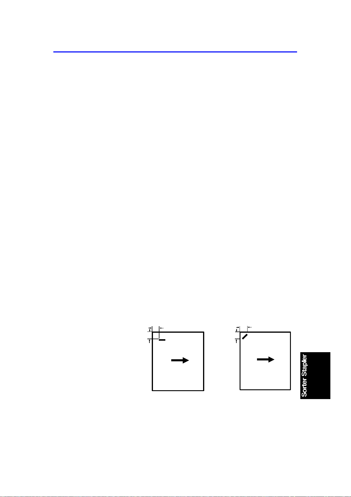
Stapling Position:
(Horizontal)
a
b
(Diagonal)
a
b
a = b
= 6 ± 2 mm
= 0.24" ± 0.08"
1
a = 10 ± 2 mm
= 0.39" ± 0.08"
b = 16 ± 2 mm
= 0.63" ± 0.08"
Page 3

SPECIFICATIONS 10 July 1992
Staple Replenishment: Cartridge exchange
(3,000 pieces/cartridge)
Power Source: DC 24V, 5V (form the copier)
Power Consumption: 50 W
Dimensions:
(W x D x H)
412 x 600 x 690 mm
(16.2" x 23.6" x 27.1")
Weight: About 25 kg, 55.1 lb
(Main Frame :22 kg, 48.5 lb
Mounting Frame: 3 kg, 6.6)
2
Page 4
10 July 1992 COMPONENT LAYOUT
2. COMPONENT LAYOUT
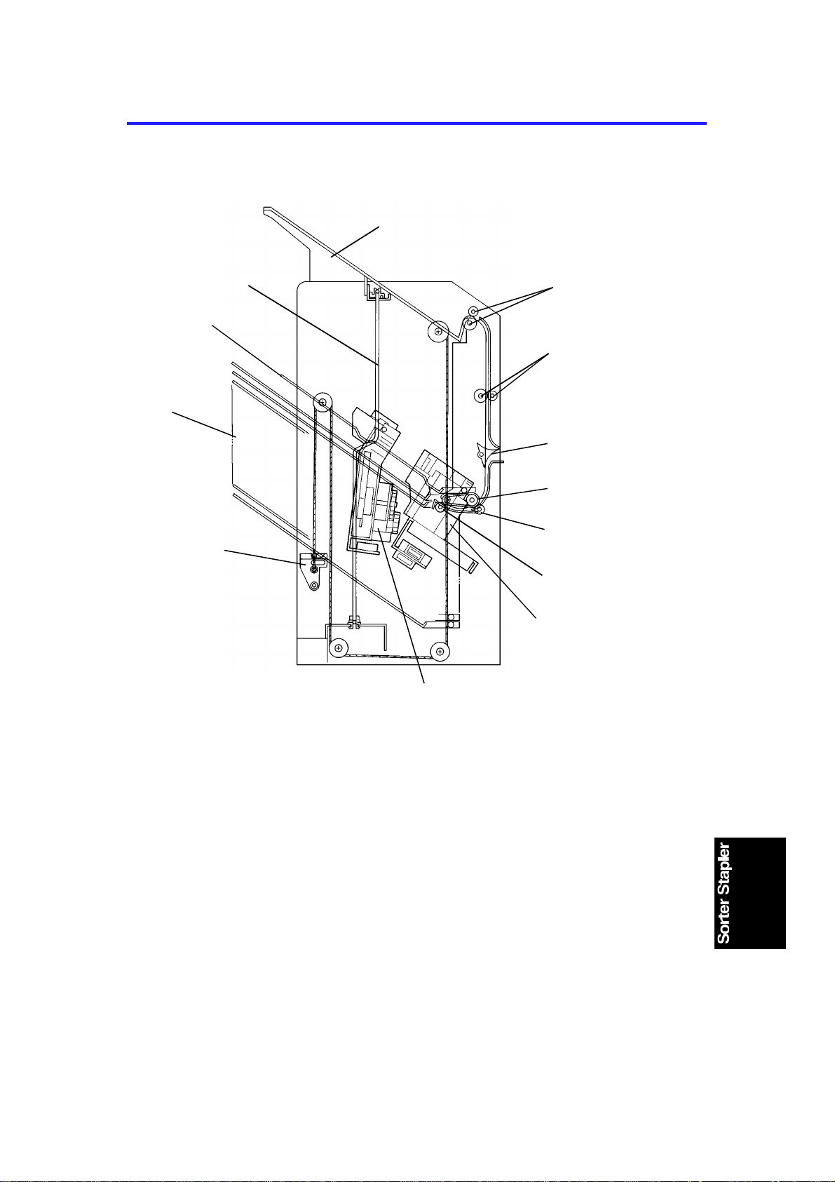
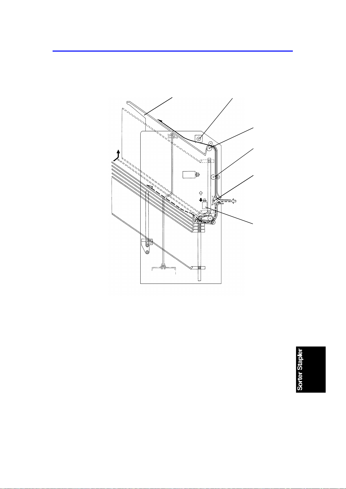
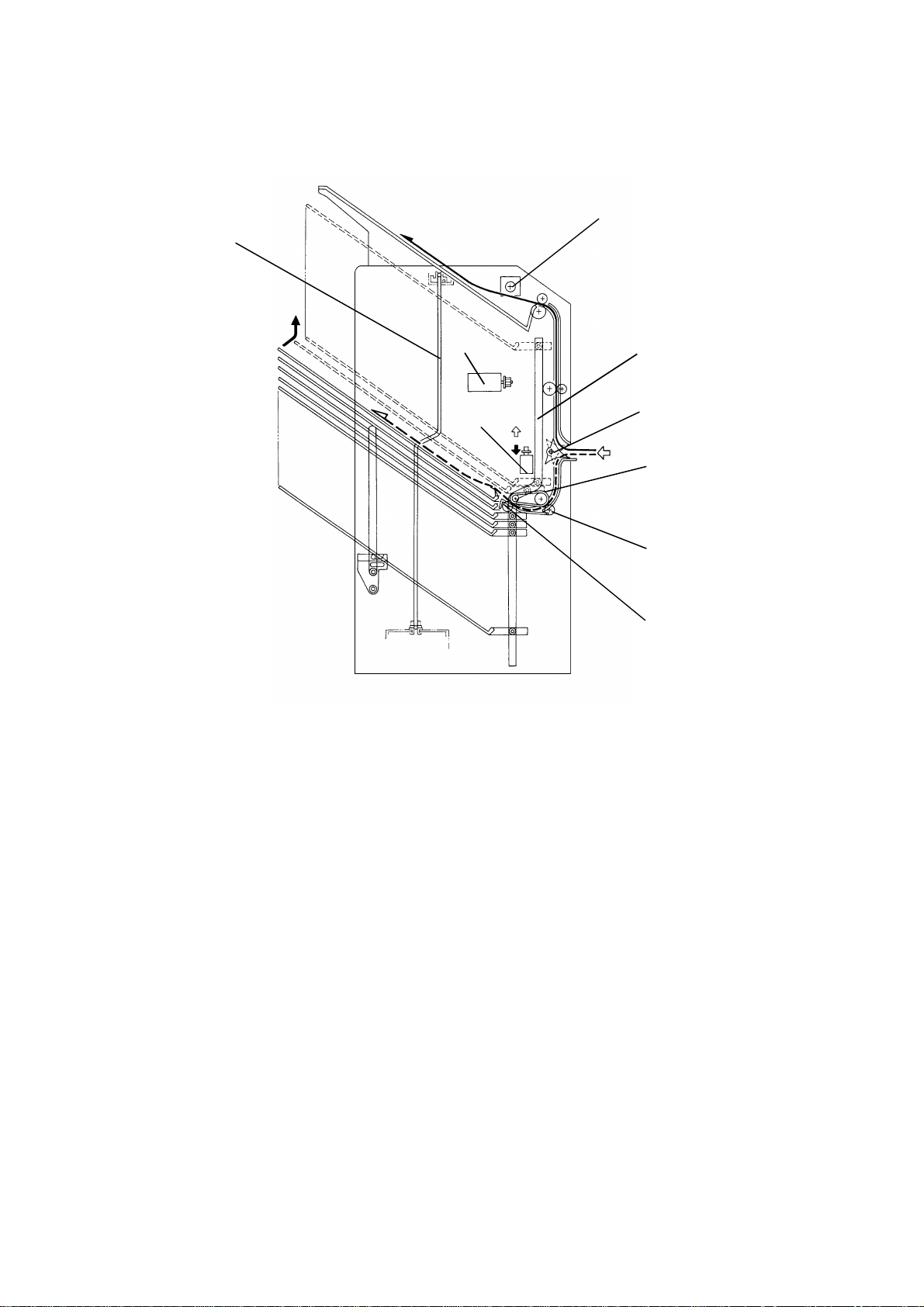
2.1 MECHANICAL COMPONENT LAYOUT
1
11
12
10
13
2
3
4
5
6
7
8
1. Proof Tray
2. Proof Tray Exit Rollers
3. Vertical Transport Rollers
4. Turn Gate
5. Bin Transport Belt
6. Bin Transport roller
7. Bin Exit Roller
9
8. Stapler
9. Grip Assembly
10. Bin Support Block
11. Bins
12. Suppor t Bin
13. Jogger Bar
3
Page 5
10
COMPONENT LAYOUT 10 July 1992
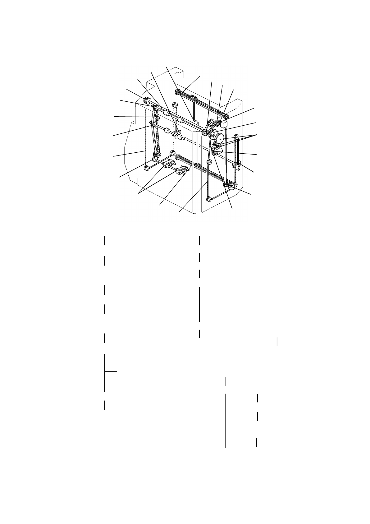
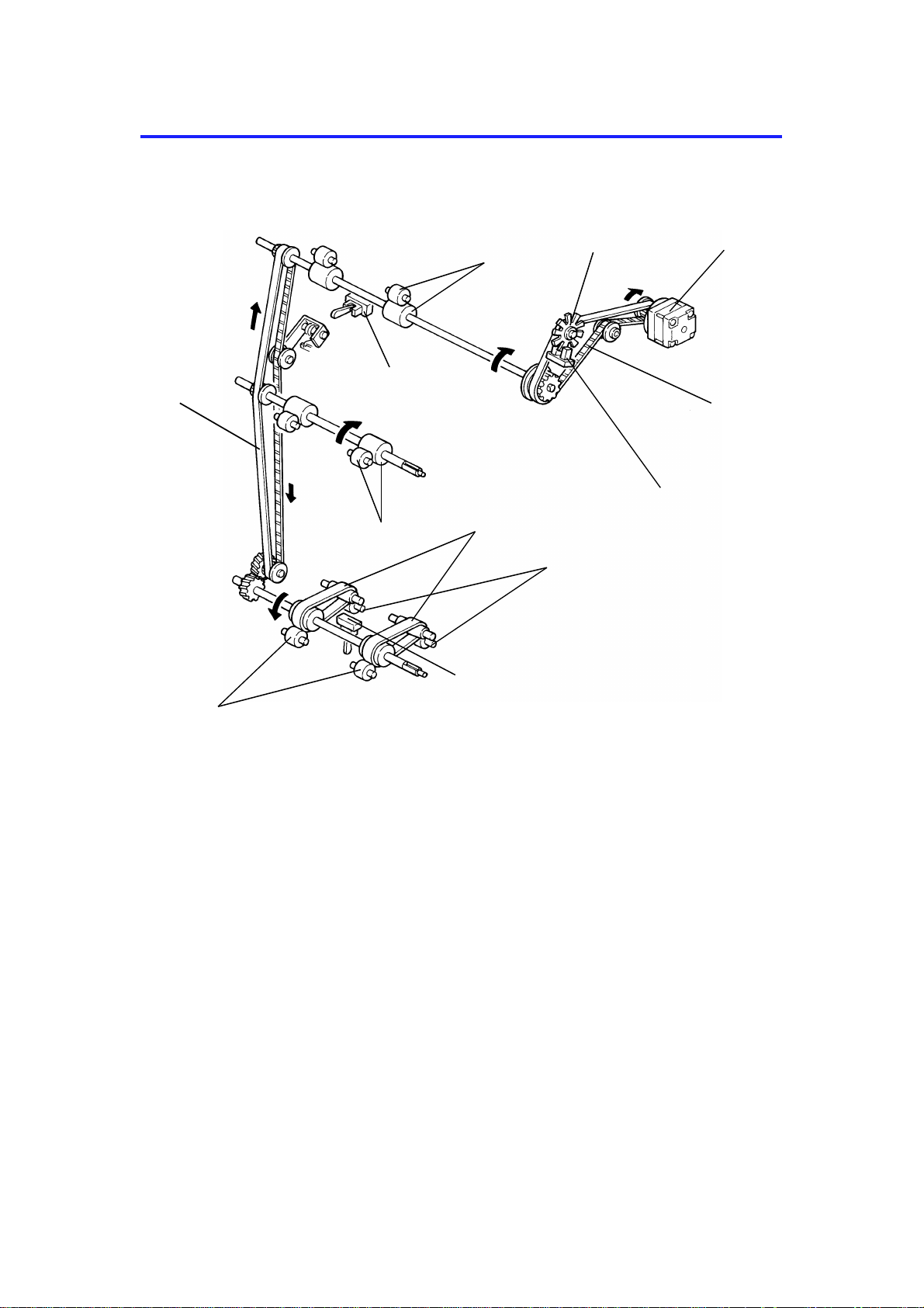
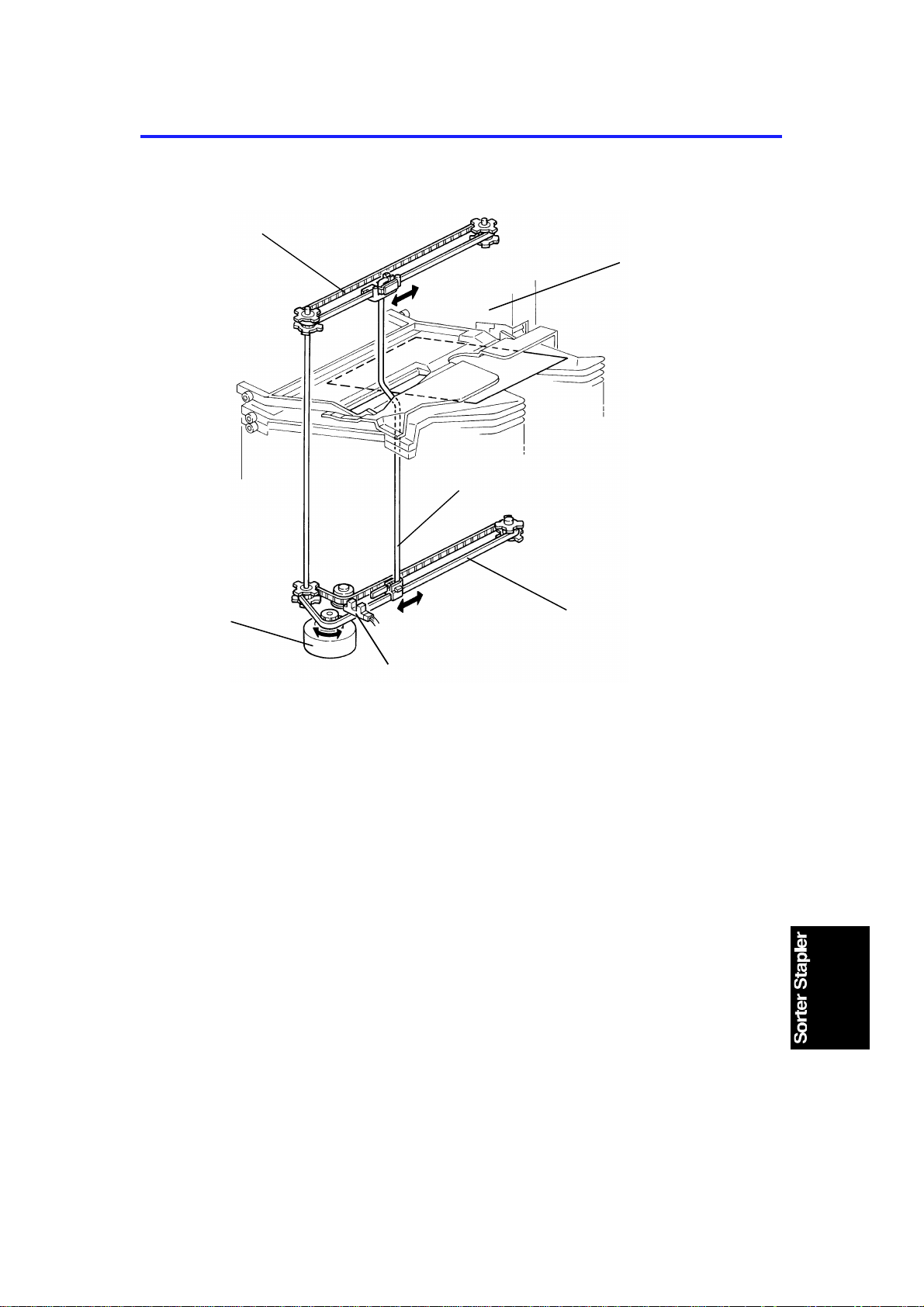
2.2 DRIVE LAY OUT
21
20
19
18
17
16
15
14
4. Roller Drive Motor Pulley
23
22
1
13
12
11. Bin Lift Motor Pulley
2
3
4
5
6
7
8
9
11
3. Rear Roller Drive Belt
2. Proof Tray Exit Roller
Pulley (Rear)
(Proof Tray Exit Roller)
19. Proof Tray Exit Roller
Pulley (Front)
18. Front Roller Drive Belt
17. Vertical Transport
Drive Pulley
15. Bin Transport Drive Gear
14. Bin Transport Belt s
8. Bin Lift Drive Belt
7. Bin Lift Gears
6. Bin Lift Gear/Pulley
12. Rear Bin Lift Wire
13. Rear Bin Support
Block
10. Jogger Motor Pulley
13. Lower Jogger Drive Belt
21. Bin Drive Shaft
20. Front Bin Lift
Pully
16. Front Bin Lift
Wire
22. Front Bin
Support Block
5. Jogger Drive Shaft
1. Upper Jogger
Drive Belt
23. Jogger Bar
4
Page 6
10 July 1992 COMPONENT LAYOUT
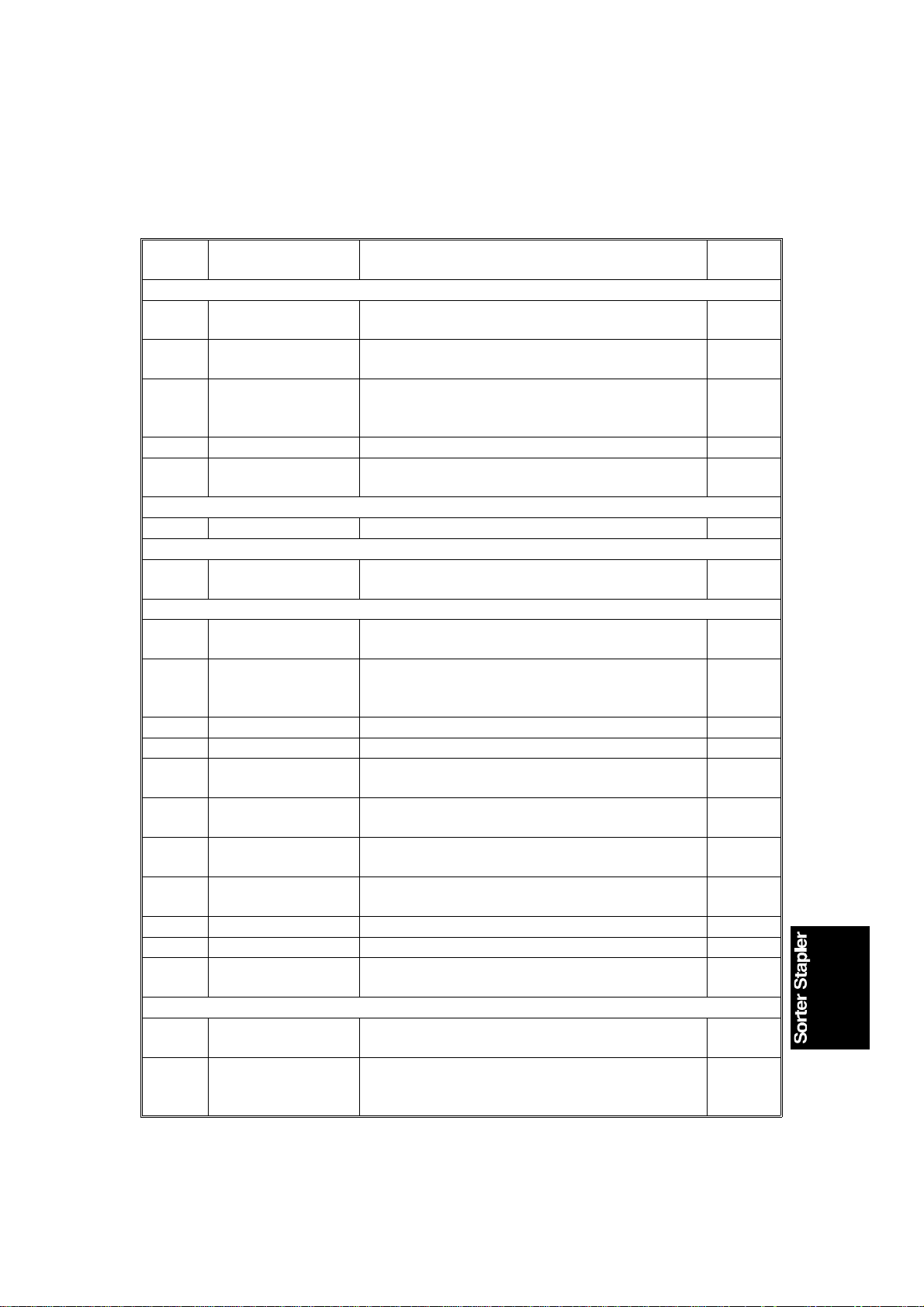
2.3 ELECTRICAL COMPONENT DESCRI P TI ON
Refer to the electrical compone nt layou t on the reverse side of the Poin t to
Point (Water proof paper) for symbols and ind ex numbe rs.
Symbol Name Function
Motors
M1 Bin Lift
M2 Jogger
M3 Grip
M4 Stapler Feeds the staples and drives the stapler hammer. 12
M5 Roller Drive
Circuit Board
PCB1 Main Control Controls all sorter stapler functions. 18
Solenoid
SOL 1 Turn Gate
Sensors
S1 Bin Lift Timing -1
S2 Bin Lift Timing -2
S3 Jogger H.P. Detects if the jogger bar is in the home position. 19
S4 Paper Detects if copies are under the hammer. 8
S5 Bin (LED)
Bin (Photo
S6
transistor)
S7 Grip H.P.
S8 Bin H.P.
S9 Bin Exit Detects paper jams at the bin exit area. 5
S10 Proof Tray Exit Detects paper jams at the proof tray exit area. 4
S11 Roller Drive Timing
Switches
SW1 Upper Lift Limit
SW2 Wire Tension
Lifts and lowers the bins via a belt, gears, and
wires.
Drives the jogger bar to jog the copies against
the front side plate.
Drives the grip assembly forward and backward
into the bin to grip the copies and bring them to
the stapling position.
Drives the proof tray exit and vertical transport
rollers, and bin transport belts.
Opens and closes the turn gate to direct the
copies into either the proof tray or the bins.
Monitors the rotation of the bin lift motor by
detecting the timing disk.
Controls the stop timing of the bin lift motor so
that the bin lift timing sensor -1 can detect the
timing disk properly.
Detects if there is paper in the bins (light emitting
element).
Detects if there is paper in the bins (light
receiving element).
Detects if the grip assembly is in the home
position.
Detects if all the bins are in the down (home)
position.
Monitors the roller drive motor speed by
detecting the timing disk.
Stops the bin lift motor when this switch detects
the upper limit position of the bins.
Stops the bin lift motor when this switch detects
the lower limit position of the bins through the bin
lift wire tension.
24 or 25
24 or 25
Index
No.
23
20
13
1
6
3
17
16
15
2
22
21
5
Page 7

COMPONENT LAYOUT 10 July 1992
Symbol Name Function
SW3 Front Door Cuts the dc 24 V line when the front door is open. 14
SW4 Sorter Stapler Set
SW5 Staple End Detects the staple end condition. 10
SW6 Staple Guide Detects if the staple guide plate is closed. 9
SW7 Staple H.P.
Cuts the dc 24 V line when the sorter stapler unit
is open.
Detects if the staple hammer is in the home
position.
Index
No.
7
11
6
Page 8
10 July 1992 BASIC OPERATION
3. BASIC OPERATION
3.1 NORMAL MODE AND SORT/STACK MODE
[E]
[C]
[G]
[F]
[B]
[A]
[D]
Copies [A] exiting the copier pass t hro ug h the entra nce guide plates to the
turn gate section. The turn gate [B] will send copies eith er to the proof tray or
to the bins, depending on the mod e.
- Normal mode - (from the turn gate section to the proof tray)
When the S/S CPU receives the motor ON signal from the copier, the roller
drive motor [C] rotates all the rollers in the S/S paper path. At the same time,
the turn gate solenoid [D] is energ ized and the turn gat e turns clockwise. The
turn gate directs copies to the proo f tray [E] through the vert ical transport and
proof tray exit rollers [F,G].
7
Page 9
BASIC OPERATION 10 July 1992
- Sort/Stack mode - (from the turn gate sectio n to the bins)
[C]
[G]
[H]
[A]
[I]
[B]
[D]
[E]
[F]
The turn gate solen oid [A] stays off and th e turn gate [B] stays up when t he
S/S roller drive motor [C] starts rot at ing . The turn gate directs copies
downward and the bin transport belt [D] exits copies t o th e bin through the bin
transport and bin exit rollers [E, F].
The jogger bar [G] th en moves th e copy towards the front and jogs it ag ainst
the front side plate to sq uare the copies.
The bin lift motor [H] turn s on when this jogging operation is almost fin ished
and advances the bin one ste p up along the bin cam track [I]. The bin lif t
motor stops at the proper timing to position the next bin at the bin exit
section. This bin movement is done for each copy in the sort mode and for
the final copy of each original in th e stack mo de.
The up and down movement of th e bins in both the sort and stack modes is
the same as that for othe r mo ving bin type sorters.
8
Page 10
10 July 1992 BASIC OPERATION
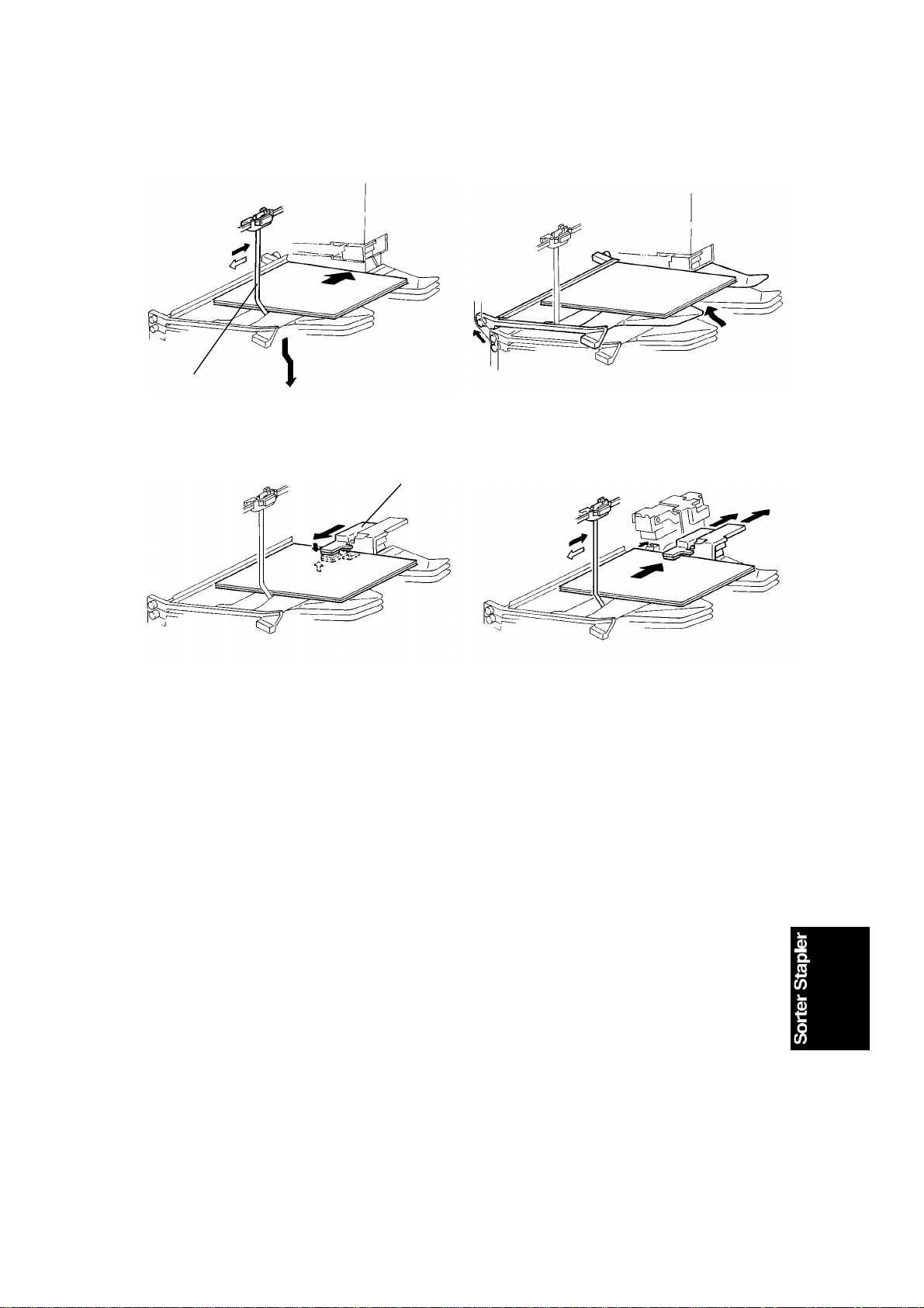
3.2 STAPLE MODE
[A]
(Fig. 1)
[B]
(Fig. 2)
(Fig. 3)
(Fig. 4)
When the final set of copies is jogged in the sort mode, th e staple unit staples
the stacked copies as follows:
(Figure 1)
If the final copy is exited to a bin other than the first one, all the bins lower to
the home position (the first bin is positioned at the bin exit sectio n). The
jogger bar [A] moves towards the front to jog the copies stacked in the first
bin. Then it stops 15mm away from the paper side edge.
(Figure 2)
The bins move one step up to place the first bin at the stap ling section.
(Figure 3)
The grippers [B] move forward, an d grip the copies.
(Figure 4)
The grippers bring the copies up unde rne at h the sta pler. At the same time,
the jogger bar jogs the cop ies stacked in the second bin as a prep aration for
the next stapling. Then the jog ge r bar ret urns to the position 15mm away
from the paper side edge.
9
Page 11

BASIC OPERATION 10 July 1992
(Fig. 5)
(Fig. 6)
(Figure 5)
The stapler staples th e cop ies.
(Figure 6)
The copies are pushed back int o the bin. Then the grippe rs ope n an d ret urn
to the home position.
The bins move one step up for the next stapling.
When the final set of copies is stapled, the bins lower and stop when the final
bin used just before the stapling operation is positioned at the bin exit section.
There are two staple modes.
1) Automatic stapling:
In ADF/ARDF mode, when the staple mode is selected before pressing
the start key, copies will be delivered to each bin an d sta ple d
automatically.
2) Manual stapling:
In sort mode, after copies are sort ed in the bins, the copie s will be stap led
when the staple key is pressed. In sta ck mode, manual stapling is
impossible.
10
Page 12
10 July 1992 TURN GATE SECTION
4. TURN GATE SECTION
[B]
[B]
[A]
[C]
[A]
[D]
The turn gate directs copies to the pro of tray or to the bins depe nding on the
mode.
In the normal mode, the turn gate solenoid [A] turns on tog et he r wit h th e
roller drive motor when the S/S CPU receives the motor ON signal from the
copier. The turn gate [B] rotates clockwise to direct copies upward [C]
through the vertical transport section to the proo f tray. The turn gate solenoid
stays on during the copy cycle s, and turns off when the proof tray exit sensor
detects the trailing ed ge of th e last copy an d the S/S CPU receives the motor
OFF signal from the copier.
In the sort, stack, or staple mode, the turn gate solenoid stays off to keep the
turn gate up so that copies are direct ed down ward [D] to the bin transport
section.
However, a certain number of pulse s (d epen din g on the pap er size) af te r t he
bin exit sensor detects the leading edge of the copy, the turn gate solenoid
turns on. When the trailin g ed ge of th e copy passes the turn gate (50 mse c.
after the S/S CPU rece ives th e pa pe r exit signal from the copier), th e tu rn
gate solenoid turns of f to direct the next copy downward. This turn gat e
movement is to correct the facecurl of the trailing part of the copy. This will
flatten the cop y, or give it a slight backcurl, and will help stack and jog copie s
in the bins smoothly.
11
Page 13
[F]
ROLLER DRIVE AND CONTROL 10 July 1992
5. ROLLER DRIVE AND CONTROL
[G]
[E]
[I]
[C]
[J]
[B]
[D]
[K]
[A]
[H]
[L]
The roller drive motor (stepper motor) [A ] drive s the proo f tra y exit rolle rs [B] ,
vertical transport rolle rs [C], bin tra nsport belts [D], bin transport rollers [E],
and bin exit rollers [F] via the front and rear roller drive belt s [G, H], pulle ys,
and gears, as shown above.
The roller drive motor turns on when the S/S CPU receives the motor ON
signal from the copier. When the proo f tray exit sensor [I] (in the normal
mode) or the bin exit sensor [J] (in th e sort /stack/staple mode) detects the
trailing edge of the final copy, the S/ S CPU inf orms th e cop ier th rou gh the
fiber cable and the interfa ce PCB . Then the copier sends the motor OFF
signal to the S/S to stop the roller drive moto r.
The S/S CPU monitors the roller drive motor speed by counting pulses of the
timing disc [K] through the roller drive timing sensor [L ].
12
Page 14

10 July 1992 ROLLER DRIVE AND CONTROL
The S/S CPU controls the moto r rota tio n at 2 speeds (no rmal an d hig h
speeds) to exit copies as fast as possible .
The normal speed depends on the copier’s p ape r tra nsp ort speed. The S/S’s
paper transport speed is almost the same but is slightly fast er th an the
copier’s.
In the normal mode, the roller drive motor changes the paper tra nsp ort speed
from normal to high (500 mm/sec., fixed) when the S/S CPU receives th e
paper exit signal from the copier. The roller drive mot or cha ng es the paper
transport speed from hig h to norma l 100 millisecon ds af te r t he proo f tra y exit
sensor detects the trailin g edge of the cop y.
In the sort/stack/sta ple mo de, the roller drive motor also changes the pap er
transport speed from normal to high and then fro m h igh to normal. The timin g
is the same as in the normal mode, bu t the bin exit sensor is used to dete ct
the trailing edge instead of the pro of tray exit sensor. The high speed is
almost double the normal speed, and it changes depending on the paper size
(900, 960 , or 1,000 mm/second).
13
Page 15
[L]
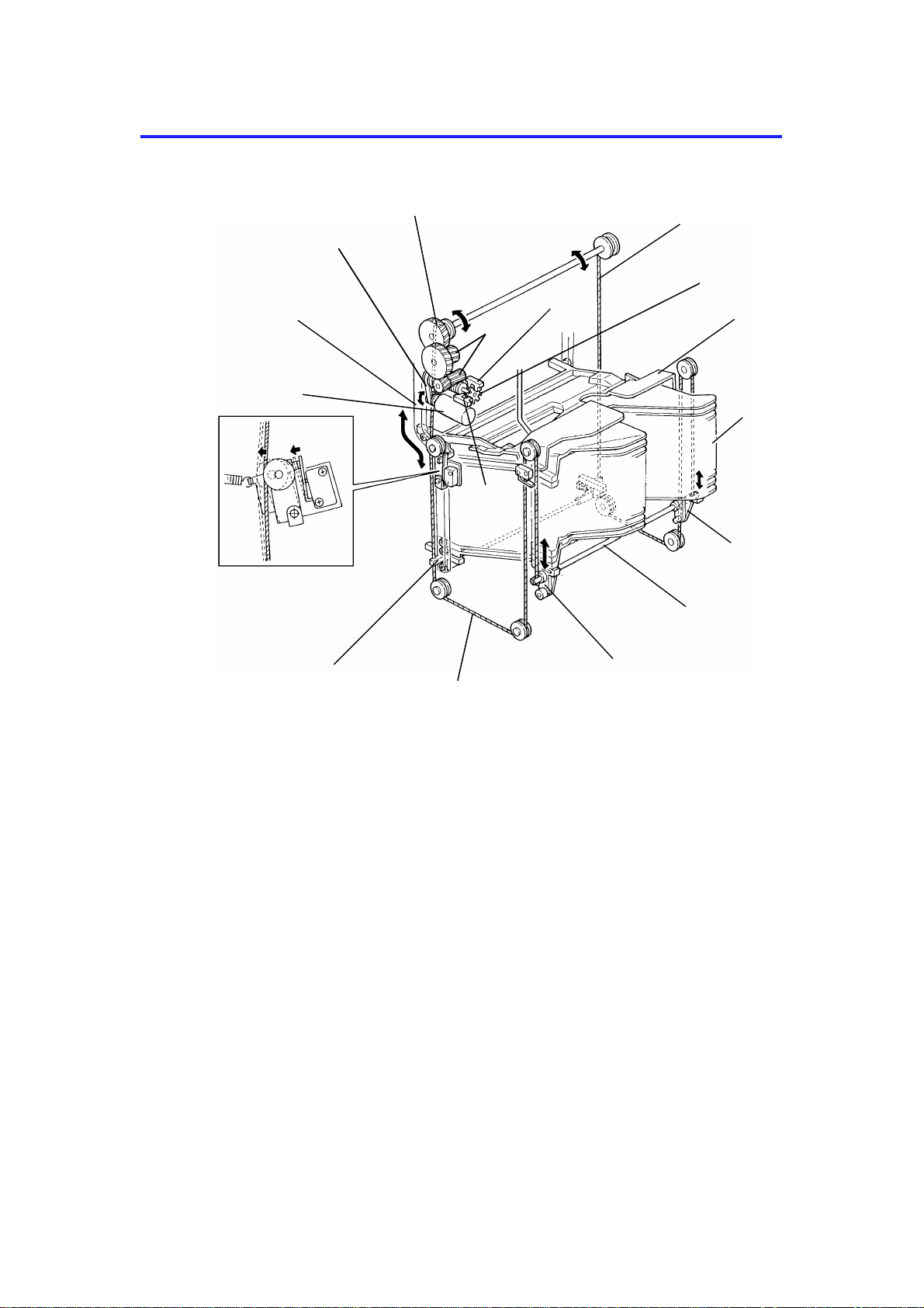
BIN DRIVE AND CONTROL 10 July 1992
6. BIN DRIVE AND CONTROL
[G]
[J]
[F]
[I]
[H]
[M]
[E]
[K]
[B]
[A]
[C]
[D]
[C]
[E]
All the 20 bins [A] and the support bin [B] are piled up on the bin support
blocks [C]. The front and rea r bin sup po rt blocks are connected by the bin lif t
shafts [D] the ends of which are fixed on the bin lift wires [E] as shown . The
bin lift motor [F] (dc motor) drives the bin lift wires through the bin lift drive
belt [G], bin lift gears [H], an d th e bin lift gear/pulley [I]. Then the bins are
driven up and down along the front an d rea r bin cam tra cks [ J].
The S/S CPU controls the amount of bin lift motor rotation by monitorin g the
pulses of the timing disc [K] th rou gh the bin lift timing senso rs 1 and 2 [L,M].
The bin lift timing sensor 1 is used for cou nting the timing pulses. The bin lift
timing sensor 2 is used to determine the mot or stop timing so that the edge of
the timing disc slots is not positioned at the timing sensor 1.
[C]
14
Page 16
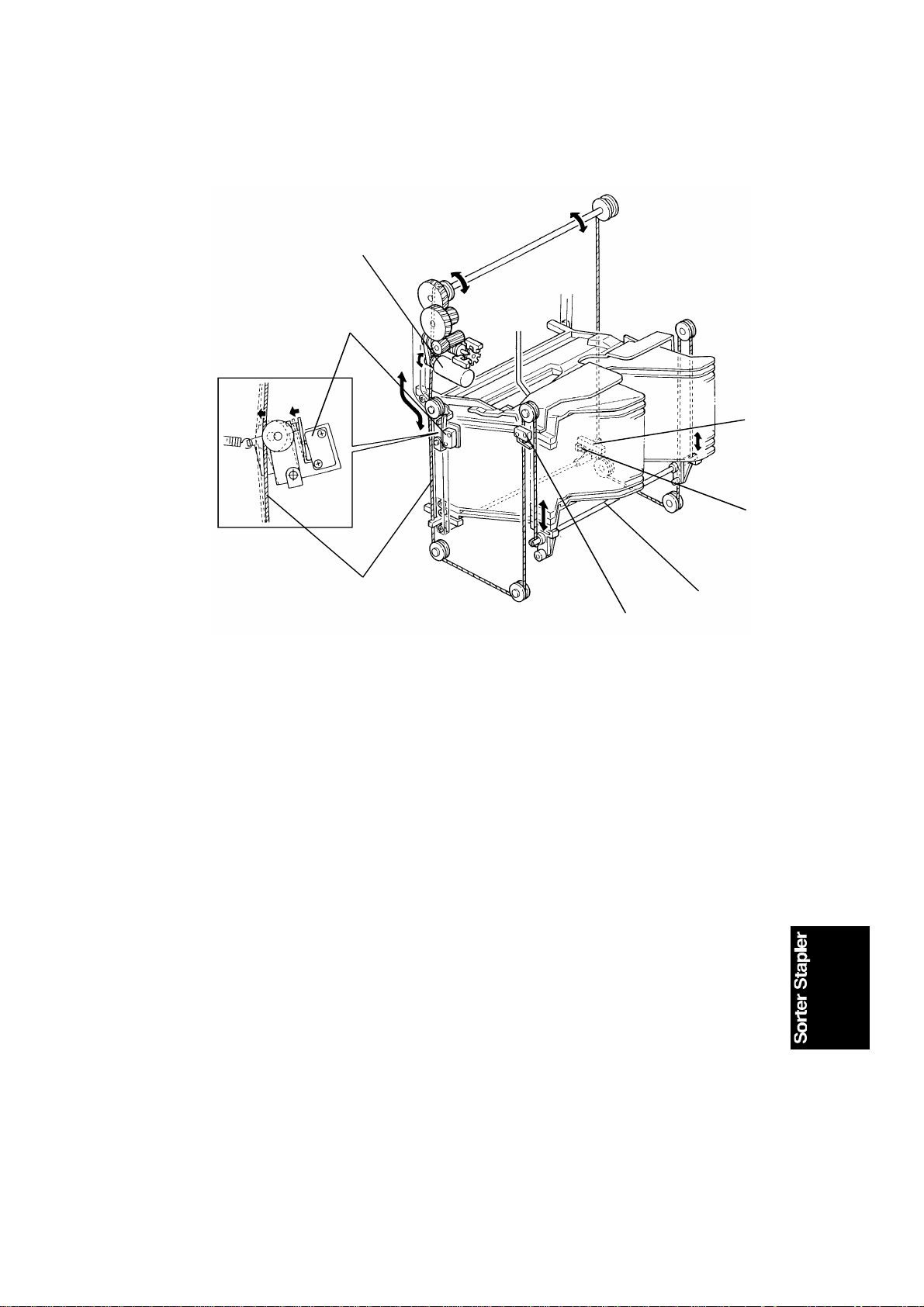
10 July 1992 BIN DRIVE AND CONTROL
[A]
[G]
[D]
[E]
[F]
[B]
[C]
If the bin lift motor [A] fails t o sto p the bin s at the hig he st po sitio n, the re ar
end of the left bin lift shaft [B] activate s the upper lift limit switch [C] (Normal
Closed type) to open the dc 24V line of the bin lift motor.
The front right bin suppo rt blo ck [D] ha s an act uator on its underside. When
all the bins are lowered and th e first bin is positioned at the bin exit sect ion,
the actuator activates the bin home position sensor [E] and the bin lift motor
turns off.
If the bin lift motor fails to stop lowering the bins at the bin home positio n, the
rear bin lift wire [F] loosens its te nsio n. Then the wire tension switch [G]
(Normal Open type) is deactivated to open the dc 24V line of the bin lift motor.
15
Page 17
BIN DRIVE AND CONTROL 10 July 1992
[A]
[B]
[E]
[C]
[D]
(Fig. 1) (Fig. 2)
[F]
(Fig. 3) (Fig. 4)
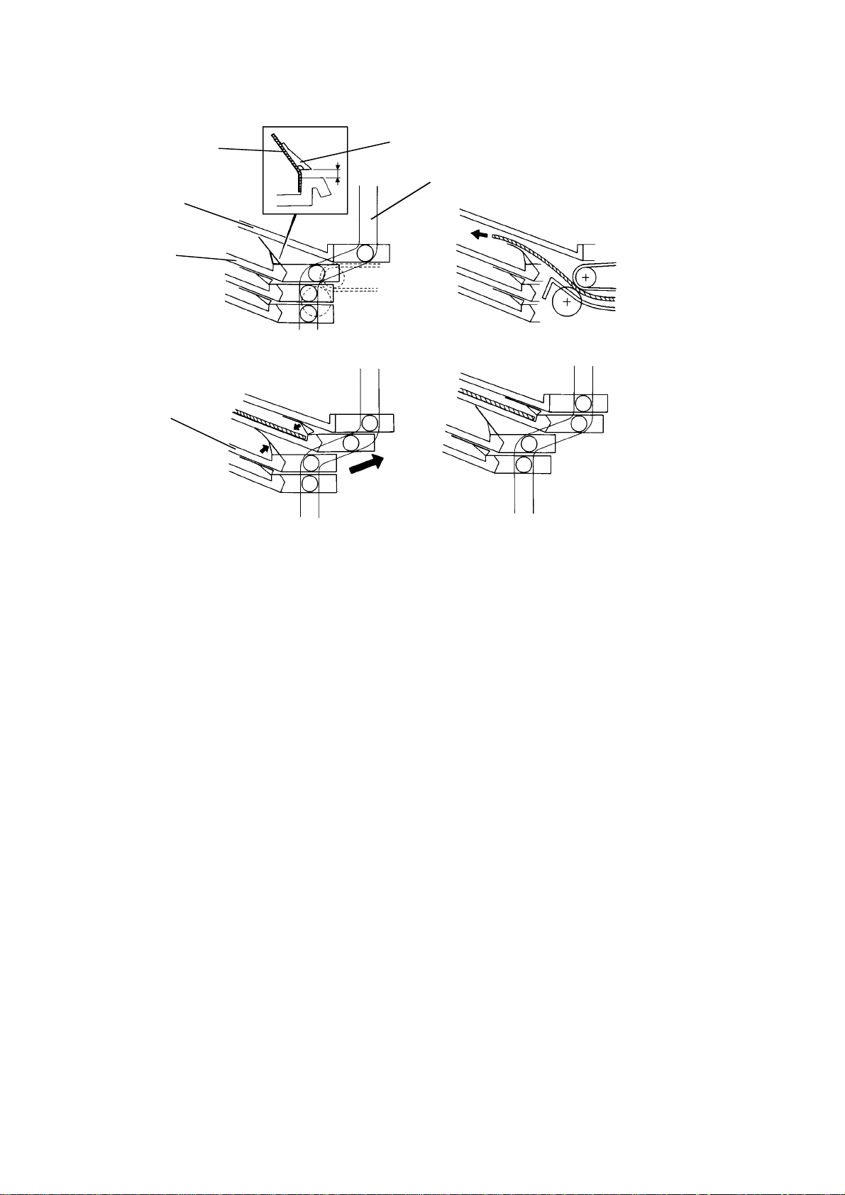
An end fence mylar [A] is stuck on each bin ent ran ce an d an end fence block
[B] is stuck on the mylar. These are stuck with two -side d ta pe, as shown in
figure 1. There is a twisted spring at the rea r end of the bin ent ran ce to raise
the end fence block and mylar. When the bin s are po sitio ne d at the bin home
position, the support bin [C] and th e first bin [D] are positio ne d at the bend of
the bin cam track [E] as shown. The supp ort and first bins have a space
between them so that the end fence mylar can fully rise until the end fence
block stops it.
The space between the support and first bin s is at the bin entra nce section
as shown in figure 2. Since the end fence mylar is t hin , a copy exits to the
first bin over the mylar. The steep angle of the bin helps th e exit ed copy slide
by its own weight under the mylar against th e bin ent ran ce.
While the bins move up alon g th e be nd of th e bin ca m track, the end fence
mylar and block of the first bin are lowered by the support bin. Those of the
second bin [F] rise as shown in figure 3.
When the bin lift motor stops, the first and second bins are positioned as
shown in figure 4. The copy in the first bin is prevented by the lowered end
fence mylar from moving out of th e jogged position. The end fe nce mylar and
block of the second bin are rea dy to receive the next copy.
16
Page 18
10 July 1992 JOGGER SECTION
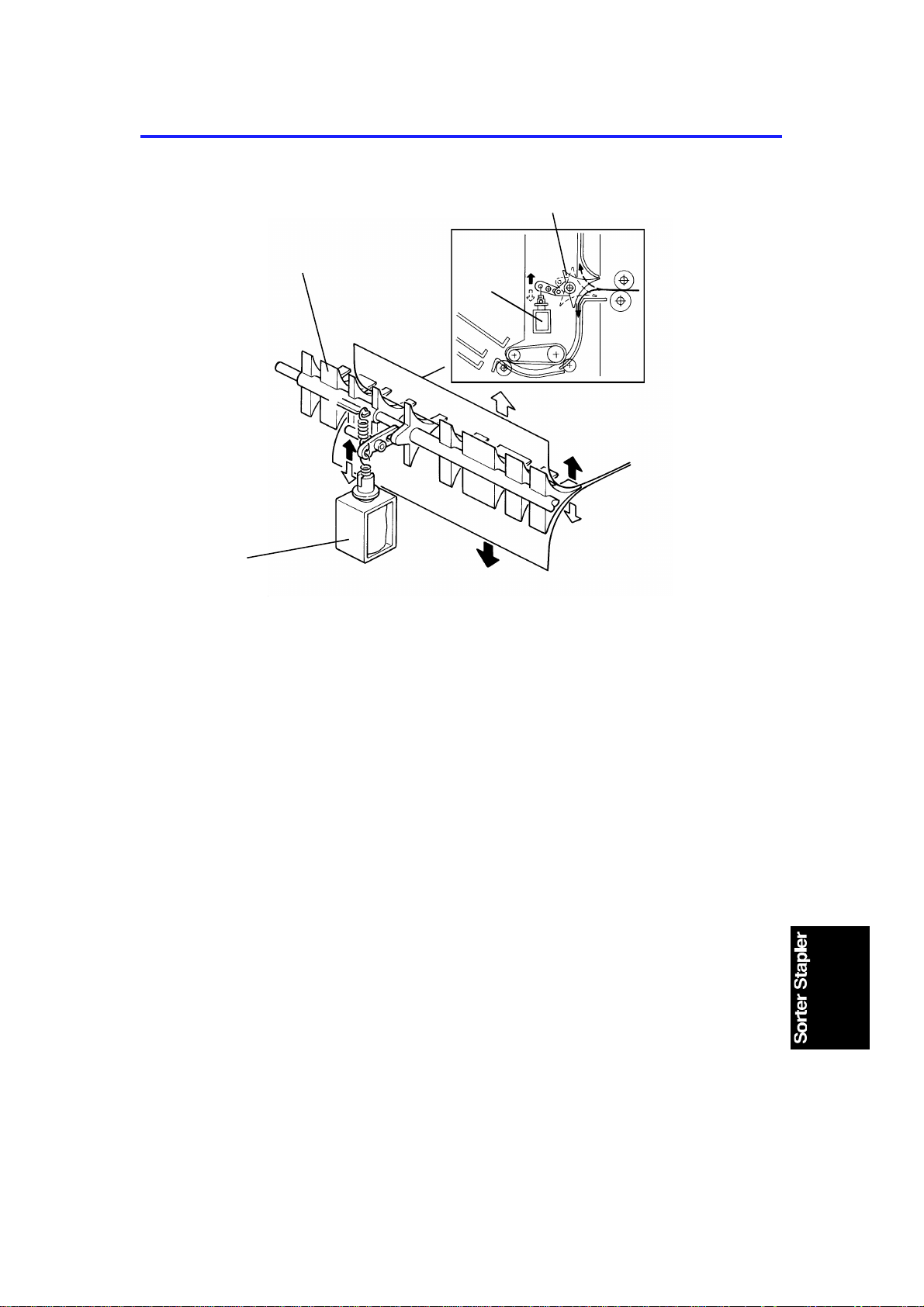
7. JOGGER SECTION
[D]
[F]
[A]
[C]
[B]
When the start key is pressed in the sort, stack, or staple mode, the copier
sends the paper size informatio n to the sorte r stap ler. Wh en a copy en ters t o
the sorter stapler entrance , th e jog ge r bar [A ] stays at the home position
which is detected by the jogger home position sensor [B].
At the appropriate timing for the selected pape r size, after the trailing edge of
the copy is detected by the bin exit senso r, the jogger motor [C] (stepper
motor) rotates and reverses to move the jogger bar via the upper and lower
jogger drive belts [D,E]. As the copy is exited into th e bin at th e center, the
jogger bar moves the copy all t he way to th e front, and pushes the pape r side
edge by 5 mm (0.2") an against the fron t side plate [F]. Then the jogger bar
moves back to the position which matches the paper width. Short ly aft er, the
jogger bar returns to its home posit ion . This jogger bar movement is
performed for each copy to square the copy stack in the exited bin.
In the automatic or manu al sta ple modes, the jogger bar also moves to
ensure squaring th e sta cked copies before stapling . How the jogger moves is
described in the Staple Mode sectio n of the Basic Operation instruct ions.
[E]
17
Page 19

JOGGER SECTION 10 July 1992
- Jogger off conditions -
1. Under the following conditions, the jogger bar does not jog after a copy is
delivered to the bin.
• If paper is loaded in a bin by hand while the sort/sta ck, or staple
mode is selected.
• If the selected paper size does not match stapling specifications.
• If copies of different width are delivered to the bins.
2. If paper is in a bin before the main switch is turned on, the sort/stack
mode is disabled when th e sort er key is p resse d.
18
Page 20

10 July 1992 GRIP ASSEMBLY
8. GRIP ASSEMBLY
[K]
[H]
[F]
[C]
[G]
[I]
[J]
(Fig. 2)
[L]
(Fig. 3)
[A]
[E]
[B]
[D]
(Fig. 1)
(Figure 1)
The grip assembly consists of th e gripper guide bracket [A] , th e gripper
assembly [B], and the bin sid e pla te [C]. The major component s of the gripper
assembly are the gripper motor [D] (stepper mot or), dual cam p lat e [E], grip
home position sensor [F], grippers [G], and grip cam follower [H].
When the copier main switch is turned on, the grip motor ro tate s and/o r
reverses to position the whole gripper assemb ly at the home positio n. The
home position is detected by the grip home position sensor and the sensor
actuator on the dual cam plate.
(Figure 2)
When the bin lift motor stops during the automatic or ma nual sta plin g cycle,
the grip motor starts the rotation. As the dual cam plate turns counter clockwise, the cam groove [I] and th e pin [J] on the gripp er guide bracket
move the whole gripper a ssemb ly a lon g the gripper guide rod [K] into the bin.
(Figure 3)
When the high portion of the grip cam [L] (small ca m of the du al cam pla te )
pushes up the grip cam follower, th e grip pe rs close to grip th e stacked copies
in the bin.
19
Page 21

[B]
GRIP ASSEMBLY 10 July 1992
(Fig. 4)
[A]
[C]
[C]
(Fig. 5) (Fig. 6)
(Figure 4)
As the dual cam plate rot at es fu rther, the cam groove and the pin move back
the whole gripper assembly with the gripp ed copie s to th e sta pling position.
Then the grip motor stops as progra mmed.
(Figure 5 and 6)
The upper gripper has a proje ctio n [A] to hook the bin side plate [B]. When
the gripper moves into the bin, the projection moves over the bin sid e pla te.
When the grippers close, the pro jection hooks the bin side plate. There fo re,
the grippers bring the sta cked copies together with the bin side plate.
When the grippers move to the sta plin g po sitio n, the S/S CPU checks if there
is paper or not through the pape r senso r [ C]. If th e pa per sensor is activated,
the stapler motor starts rotat ing .
When the stapler motor stops, the grip mot or starts rotating in reverse. The n
the gripper assembly brings back the stapled copies into the bin, the grippers
open, and the gripper assembly returns to the home position.
20
Page 22

[I]
10 July 1992 STAPLER
9. STAPLER
[B]
[D]
[E]
[C]
[A]
[G]
In the automatic or manual stapling mode, the stapler motor [A] rot at es when
the grip motor stops rotat ing after the grippers bring the stacked copies to the
staple position.
[F]
[B]
[H]
[H]
[J]
The staple gear [B] rotate s coun te rclockwise , an d the pin on the gear rot at es
the staple arm [C] counterclockwise, then clockwise. The rat che t [D] lowers
and rises to rotate the ratchet whe el [E] counterclockwise. Then the st aple
feed rollers [F] turn via gears to feed a staple shee t to the hamme r.
While both the front and rear staple arms rotat e count erclo ckwise, the
hammer [G] lowers. At the same time, the stap le cam pla te [H] lifts the
clincher [I]. The hammer and the clin che r stap le th e cop ies. Then , while the
staple arms rotate clockwise, the hammer rises and the clincher lowers.
When the staple home position switch (Normal Closed type) [J] is
deactivated, the stapler mot or sto ps.
21
Page 23

STAPLER 10 July 1992
[B]
[E]
[A]
[C]
[D]
When all the staple sheet s ar e fe d ou t of the st aple cartridge, a notch cut-in
of the staple pressure plate [A] deactiva tes the staple end switch (Normal
Closed type) [B]. The S/S CP U send s the stap le en d signal to the copier.
After the staplin g job for all the bins is completed, the Ad d Staple indicator
lights on the copier operation panel and the Read y indica tor turns off
whenever the staple mode is select ed .
Staple jams are easily cleared by opening the staple guide plate [C]. The
staple guide switch (Normal Closed type ) [ D] dete cts if th e sta ple guid e pla te
is closed or open. When the S/ S front door and S/S unit itself are closed with
the staple guide plate op en , the Add Staple indicat or ligh ts on the copie r
operation panel.
The stapler can be swung on the stapler support bracket [E ] an d it ha s tw o
lock positions . One is for horizontal stapling and th e ot he r is fo r diagonal (25
degrees) stapling.
22
Page 24

10 July 1992 STAPLER
- Staple inoperative conditions -
1. Under the following conditions, the staple mode is inoperative when the
staple key on the operation panel is pressed.
• If paper is in a bin before the main switch is turned on.
• If the selected paper size does not match st apling specifications.
2. Under the following conditions, the staple mode is canceled.
• If the paper is loaded in a bin by hand while the staple mode is
selected.
• If the only one sheet is delive red to the bin.
• If the number of she ets delivered to the bin exceeds the stapler
capacity.
Stapler capacity: 2 to 20 sheets for A4, B5, and 81/2 "X11"
2 to 10 sheets for B4, A3, 81/2"X14", and
11"X17"
The stapler capacity can be extended up to 25 or 15 by changin g th e
SP mode setting (Staple Limit). (The staple function is not
guaranteed.)
• If jogger operation has no t be en perf ormed.
• If copies in all the bins are sta ple d.
3. Under the following conditions, the manual stapling mode in sort mode is
inoperative.
• If paper is loaded in a bin by hand while the sort mode is selected.
• If the paper size in the bin does not match stapling specifications.
• If only one sheet is delivered to th e bin.
• If copies of different width are delivered to the bin.
• If copies already stapled are left in the bin.
23
Page 25

JAM DETECTION AND STAPLE ERROR 10 July 1992
10. JAM DETECTION AND STAPLE ERROR
10.1 SORTER JAMS
[Normal Mode]
Copier Paper
Exit Sensor
Proof Tray
Exit Sensor
[Sort/Stack/Staple
Mode]
Copier Paper
Exit Sensor
Bin Exit
Sensor
122 pulses
(122)
Reset
(200)
88 pulses
(88)
Reset Reset
(200)
ON
J5
(0)
ON
J1
(0)
Reset
230 msec
Reset
Reset
200 pulses
Reset
600 msec
Reset
200 pulses
8 seconds
OFF
8 seconds
(0)
J6
OFF
J2
(0)
J3
OFF
(0)
J7
OFF
(0)
J4
OFF
J8
OFF
[A]
[B]
The sorter stapler main contro l board dete cts pape r jams in the sorte r stapler,
or between the sort er sta pler and the copier. The S/S CP U uses the paper
exit ON/OFF signal from the copie r, an d th e proof tray exit sensor [A] (in
normal mode) or the bin exit sensor [B](in sort/stack/staple mode) to detect
the jams.
The actual jam check timings in the no rmal and sort/stack/staple mode s are
shown above. There are two time scales: one in seconds and milliseconds,
and one in pulses. The pulses are the timing pulses from the roller drive
timing sensor. Since the paper t ran spo rt speed (normal speed) of the sorter
stapler depends on that of the copier, the sorte r st apler cannot operate on a
fixed time scale. Therefore , to match the sorter stapler speed to the copier’s,
the copier sends a signal to S/S CPU; this controls the normal speed of the
roller drive motor (high speed ne ver cha ng es) and this generates the pulse
rate.
24
Page 26

10 July 1992 JAM DETECTION AND STAPLE ERROR
If the proof tray exit senso r o r the bin exit se nso r is act uated when the sorter
stapler unit or the front door is opened and closed, or when the main switch is
turned on, a sorter jam signal is sent to the copier.
Sorter jam conditions are rese t by op en ing and clo sing the sorter stapler unit
or the front door after clearing jammed paper.
When an abnormal condition of the main motor, bin lift mot or, or jogg er mot or
is detected for the first time, the copier’s operation panel will indicate a sorter
jam. When the abnormal condition is detected for the second time, the S/ S
CPU sends an error signal to the copier. The copier’s opera tio n panel will
indicate a service call code.
10.2 STAPLE ERROR
The sorter stapler main control board detects a staple error when the
following conditions are detected. The copier’s operation pan el will indica te a
sorter jam, and stapling op era tio n will st op in theses case s.
• If the paper sensor is actua ted when the sorter stapler or the front
door is opened or closed, or when the main switch is turned on.
• If the paper sensor is actua te d when the grip assembly retu rns to the
home position after the stapling operation .
• The first time an abnormal condition of the stapler motor or grip
motor is detected.
The second time an abnormal condition is detected, the copier’s
operation panel will indicate a service call code.
25
Page 27

Motor
OFF signal
0 1 10 2152 3 4
6
7 8 9 11 12 13 14 15 16 17 18 19 20
(sec)
100ms
50ms
1pls
OFF
ON
100ms
OFF
exit
High
Speed
Normal
Speed
OFF
Up
230ms
Down
60ms
OFF
Forward
Reverse
1 2 3 4 5
5 4 3 2 1
signal
SS paper
RXD
TXD
TIMING CHARTS 10 July 1992
11. TIMING CHARTS
Timing Chart 1: Normal Mode (A4 sideways, 5 copi es)
Interface
Turn Gate
Solenoid
RXD
TXD
01 105234
Normal
Motor ON
mode
signal
signal
ON
OFF
100ms
100ms
SS paper
exit signal
7 8 9 11 12 13 14
6
Paper exit signal
from copier
High speed
Roller Drive
Motor
Proof Tray
Exit Sensor
OFF
Normal speed
Timing Chart 2: Sort Mode (A4 sideways, 2 copies for 5 bins)
Interface
Turn Gate
Solenoid
Motor ON
signal
Paper exit signal from copier
16
(sec)
Motor OFF
signal
Roller
Drive
Motor
Bin Lift
Motor
Jogger
Motor
Bin Exit
Sensor
Bin Number
Paper Size
A3 61 220 ms 40 ms 900
B4 43 225 ms 0 ms 900
A4 sideways 1 230 ms 60 ms 960
A4 lengthwise 21 350 ms 0 ms 900
B5 sideways 1 250 ms 74 ms 1000
B5 lengthwise 8 330 ms 0 ms 900
11" x 17" 65 220 ms 0 ms 900
1/2" x 14" 41 525 ms 0 ms 900
8
1/2" x 11" sideways 1 230 ms 265 ms 960
8
1/2" x 11" lengthwise 18 725 ms 0 ms 900
8
Turn Gate Sol. ON
Timing (Pulses)
Bin Lift Motor
ON Timing
26
Jogger Motor
ON Timing
High Speed
(mm/s)
Page 28

10 July 1992 TIMING CHARTS
Timing Chart 3: Staple Oper ati on (A4 side ways, 2 copies for 5 bins)
IInterface
Bin Lift Motor
Jogger Motor
Grip Motor
Stapler Motor
01 1052 3 4 6 7 8 9 1112131415
RXD
TXD
OFF
OFF
Reverse
500ms
Staple ON
signal
Forward
Up
OFF
Staple count
signal
Forward
Reverse
ON
Job completion
signal
Down
1 staple cycle
(sec)
Returns to
H.P.
27
Page 29

ACCESSORY CHECK 10 July 1992
12. ACCESSORY CHECK
Check the quantity and condition of the accessories in the box as listed
below:
1. Harness Cover .................................................................. 1
2. Proof Tray..........................................................................1
3. Staple Cartridge ................................................................ 1
4. Decal Switch ...................................................................... 1
5. Fiber Optics Cable ............................................................. 1
6. Staple Position Decal ......................................................... 1
7. Stepped Screw .................................................................. 1
8. Philips Truss Head Screw -M4 x 6...................................... 3
9. Philips Pan Head Screw -M4 x 12 ...................................... 4
10. Grounding Screw with Toothed Washer –M4 x 8...............1
11. New Eq uipment Condition Report
(–17 machine only) ............................................................1
12. Envelope for N.E.C.R.
(–17 machine only) ............................................................1
13. Installation Procedure ....................................................... 1
28
Page 30

10 July 1992 INSTALLATION PROCEDURE
13. INSTALLATION PROCEDURE
[A]
[B]
[C]
NOTE: The sorter ad apt er (A328) should be installed before the sorter
stapler is.
The interface PCB (A344) is neces sary for so rter stapler
installation.
CAUTION: Unplug the copier power cord before starting the following
procedure.
1. Remove the strips of tape [A] and open the front door [B].
2. Remove the strips of tape [C] from the staple unit an d close the front
door.
[A]
29
Page 31

INSTALLATION P ROCED URE 10 July 1992
[A]
[D]
[B]
[E]
[C]
[E]
[F]
3. Remove the copier rear cover [A] ( remove 2 screws and loosen 2
screws).
4. Remove the 4 screws securing the cop ier left cover [B].
5. Remove the cover plates [C,D] from the left cover by cutting them with
cutting pliers.
6. Release the lock lever [E] of the sorter stapler and un hook th e S/ S
mounting frame [F] as shown.
30
Page 32

10 July 1992 INSTALLATION PROCEDURE
[A]
[B]
[G]
[C]
[D]
[F]
[E]
7. Install the S/S mounting frame [A] on the copier as shown
(4 screws – M4 x 12).
NOTE: When hooking the S/S mounting frame on the left side of the
copier, make sure that the positioning hooks [B] of the frame are
properly inserted in the positioning holes [C] of the copier.
8. Install the sorter stapler [D] on the S/S mounting frame (2 hinge pins at
the rear).
9. Connect the link lever [E] with the sorter stapler by using stepped screw
[F], and then close the sorter stapler.
10. Install the proof tray [G] (1 screw) as shown.
31
Page 33

INSTALLATION P ROCED URE 10 July 1992
[C]
[H]
[I]
[G]
[B]
[D]
[A]
[E]
[F]
11. Set the 2 locking supports [A] on the copier main board bracket [B] and
install the interface PCB [C] onto CN114 on the main board as shown.
12. Pass the fiber optics cable [D] through the access hole [E] and connect
to CN110 [F] on the main board of the sorter stapler.
13. Run the fiber optics cable as shown and set it in the wire saddles [G].
14. Connect the other end [H] of the fiber optics cable to CN703 [I] on the
interface PCB.
32
Page 34

10 July 1992 INSTALLATION PROCEDURE
[B]
[D]
[A]
[E]
[C]
[F]
15. Pass the sorter stapler harness [A] through the access hole [B].
16. Secure the protective earth wire [ C] on the bracket [D] (1 grounding
screw with toothed washer), and couple the connector (4P white) [E].
17. Install the harness cover [F] on the sorter stapler as shown (2 screws).
18. Install the copier rear cover.
33
Page 35

INSTALLATION P ROCED URE 10 July 1992
[B]
[A]
[C]
[D]
19. Remove the left plastic cover [A] on the operation panel and install the
sorter key top and cover [B] instead.
(The sor ter key top and co ver are provided as accessories for the copier.)
20. Stick the main switch decal [C] on the copier as shown.
21. Stick the staple position decal [D] on the ARDF as shown. (If there is no
ARDF, stick it on the corresponding position of the platen cover.)
34
Page 36

10 July 1992 INSTALLATION PROCEDURE
[C]
[B]
[A]
[D]
[C]
22. Open the front door of the sorter stapler and swing the staple unit [A] up .
23. Remove the green plastic clip [B] from the staple cartridge [C] and
correct the position of the staple sheet [D] if necessary.
24. Install the cartridge in the stapler while holding the staple unit.
25. Set the staple unit at the original position, close the S/S front door, and
plug in the copier.
26. Tur n on the copier main switch and test the operation of the sorter stapler.
NOTE: The stapler will not be stapling for the first 10 or so copies until
the first staple comes to the proper position from the cartridge.
35
Page 37

SERVICE TABLE (MAIN CONTROL BOARD) 10 July 1992
14. SERVICE TABLE (MAIN CONTROL BOARD)
14.1 DIP SWITCHES
DIP SW 100
1 2 3 4 5 FUNCTION Remarks
0 0 0 0 0 Standard
1 0 0 0 Sorter Free Run #1
*1
0 1 0 0 Staple Free Run #2
1 1 0 0 Sorter&Staple Free Run #3
0 0 0 0 1 Bin Sensor Adjustment
NOTE:*1 Confirm the setting from DIP SW 100 -2 to -5 before turning on
DIP SW 100 - 1 (Start SW function).
Turn off DIP SW 100 - 1 to stop the function.
Remarks
#1 The roller drive motor turns on.
The sorting operation is repeat ed from th e 1st bin to the 20th bin .
Operated compon en ts: • Turn gate sole noid
• Bin lift motor
• Jogger motor
#2 The stapling operation is repeated from t he 1st bin to th e 20 th
bin. When there is no paper in a bin , the stapling operation is
skipped for that bin.
Operated compon en ts: • Bin lift motor
• Grip motor
• Stapler motor
#3 #1 and #2 are repeated together.
Combinations other t ha n th ose abo ve are used at the factory.
14.2 LED AND VARIABLE RESISTOR
LED No. VR No. FUNCTION
100 100 Adjusts bin sensor sensitivity.
14.3 TEST POINTS
Number FUNCTION
TP100 GND
TP101 +24V
TP102 +5V
36
Page 38

10 July 1992 REPLACEMENT AND ADJUSTMENT
15. REPLACEMENT AND ADJUSTMENT
15.1 STAPLER REMOVAL
[A]
[B]
[D]
1. Open the front door [A] of the sorter stapler and swing the staple unit [B]
up.
2. Remove the staple unit cover [C] (1 screw).
[C]
3. Remove the stapler [D] (1 screw and 1 connector).
37
Page 39

REPLACEMENT AND ADJUSTMENT 10 July 1992
15.2 GRIP ASSEMBLY REMOV A L
[A]
[C]
[B]
[D]
1. Remove the proof tray [A ] (1 screw).
2. Swing out the sorter stapler and disco nn ect the link lever [B] (1 stepped
screw).
3. Remove the front cover [C] (remove 2 screws and loosen 2 screws).
4. Remove the grip assembly [D] (2 screws and 1 connector).
38
Page 40

10 July 1992 REPLACEMENT AND ADJUSTMENT
15.3 BIN REPLACEMENT
[B]
[A]
[C]
1. Remove the sorter stapler from the copier.
2. Remove the proof tray [A ] (1 screw).
3. Remove the jogger bar [B] as shown.
4. Remove the upper securing screw of the bin link [C] (1 screw each).
39
Page 41

REPLACEMENT AND ADJUSTMENT 10 July 1992
[C]
[D]
[A]
[B]
5. Remove the support bin [A] and bins [B].
(1) Hold the bin [A or B] with both hands.
(2) Push the bin forward until the wh eels [C] reach the bend.
(3) Push the left side of the bin forward and pull that side up.
(4) As you pull the left side up, the right whe el will le ave its t rack.
(5) When the left wheel re ach es the slot [D], pull the bin out.
40
Page 42

10 July 1992 REPLACEMENT AND ADJUSTMENT
[C]
[E]
[D]
[A]
[B]
6. Install the support bin [A] and bins [B].
(1) Hold the bin top side up with both hands.
(2) Tilt the bin so the left side is higher t hen th e right side.
(3) Pass the left wheel [C] through the slot [D], at th e same time, pass
the right wheel [E] just be low th e stapler opening.
(4) Set the left wheel in to the left track, then push the right whe el into the
right track.
41
Page 43

REPLACEMENT AND ADJUSTMENT 10 July 1992
15.4 BIN LIFT WIRE REPLACEMENT
15.4.1 Wire Removal
[C]
[A]
[B]
[D]
[E]
1. Remove the sorter stapler from the copier.
2. Remove the following parts:
• Proof Tray [A] (1 screw).
• Front Cover [B] (loosen 2 screws and remove 2 screw)
• Rear Cover [C] (4 screws)
• Support Bin [D] (see Bin Replace men t)
• Bins [E] (see Bin Replacement)
42
Page 44

[B]
10 July 1992 REPLACEMENT AND ADJUSTMENT
[D]
[E]
[A]
[F]
[C]
<Front side>
3. Swing the bin shaft cover [A ] as sho wn (2 screws an d 1 conne cto r )
4. Remove the 3 fixing screws of the stapler unit [B].
5. Remove the bin support block stopper [C] as shown.
6. Remove the wire pulley [D] (1 E-ring).
NOTE: Be caref ul no t to lose th e paralle l pin [E].
7. Remove the bin lift wire [F].
43
Page 45

REPLACEMENT AND ADJUSTMENT 10 July 1992
[B]
[E]
[A]
[D]
[C]
<Rear side>
8. Remove the main control board [A] (1 screw, 13 connectors and 6 locking
supports).
9. Remove the bin lift shaft cover [B] (2 screws).
10. Remove the timing sensor bracket [C] (1 screw).
11. Remove the bin drive bracket [D] (1 grou nding screw, 1 connector and 2
wire saddles).
12. Remove the bushing [E].
44
Page 46

10 July 1992 REPLACEMENT AND ADJUSTMENT
[C]
[B]
[A]
[D]
12. Remove the bin lift block stopper [A ] as shown.
13. Remove the wire pulley/gear [B] (2 E-rings).
NOTE: Be caref ul no t to lose th e paralle l pin [C].
14. Remove the bin lift wire [D].
45
Page 47

[A]
[E]
[M]
[H]
[L]
REPLACEMENT AND ADJUSTMENT 10 July 1992
15.4.2 Wire Installation
[E]
[B]
[A]
[D]
[K]
[I]
[F]
[G]
[Rear]
[Q]
[P]
[J]
[D]
[H]
[Front]
[O]
[C]
[F]
[G]
[P]
[N]
[A]
550.4 mm (21.67")
[F]
877.6 mm
(34.55")
[P]
1. Put the bead [A] at the end of the wire in the slot of the wire pulley [B , C],
[Q]
2. Insert the parallel pin [D] into the bin drive shaft [E] and then push in the
wire pulleys.
3. Wind the wire once as shown and put the bead [F] in the slot of the bin
support block [G].
4. Put the bin support block stopper [H] on the bin support block.
5. Place the wire on the pulleys [I/J/K, L/M/N/O ] and pu t the bead [P] in the
slot of the bin lift shaft [Q].
46
Page 48

10 July 1992 REPLACEMENT AND ADJUSTMENT
15.5 VERTICAL TRANSPORT UNIT REMOVAL
[C]
[B]
[A]
[G]
1. Remove the sorter stapler from the copier.
[D]
[F]
[E]
2. Remove the proof tray, the front cover, the rear cover, and the upper
cover.
3. Remove the upper hinge [A] (2 screws) and the sorter stapler set switch
bracket [B] (1 screw).
4. Remove the grounding screw [C] and disconnect the main harne ss [D] (5
connectors and 3 harness clamps).
5. Remove the timing belt [E ] from the pulley [F].
6. Remove the vertical transport unit [G] (8 screws).
47
Page 49

REPLACEMENT AND ADJUSTMENT 10 July 1992
15.6 MAIN CONTROL BOARD REPLACEMENT AND
ADJUSTMENT
15.6.1 Main Control Board Replacement
[A]
1. Remove the proof tray and the rear cover.
2. Disconnect the main control board connectors and fiber cable.
3. Replace the main control board [A] and connect the connectors.
4. Turn on the copier main switch.
5. Adjust the bin sensor (see next page).
6. Turn off the main switch.
48
Page 50

[B]
10 July 1992 REPLACEMENT AND ADJUSTMENT
15.6.2 Bin Sensor Adjustment
[C]
[A]
1. Turn on DIP SW100-5 [A]
2. If LED100 [B] is on, turn VR100 [C] counterclockwise until LED100 turn s
off.
3. Turn VR100 clockwise until LED100 just turns on.
4. Turn off DIP SW100-5.
49
Page 51

REPLACEMENT AND ADJUSTMENT 10 July 1992
15.7 BELT TENSION ADJUSTMENT
[A]
[B]
a: Bending (mm/inches)
1. Remove the respective covers for the following belt tension adjustment:
Timing Belt [A]
(Roller Drive Motor)..................................... Proof Tray
Rear Cover
Timing Belt [B]
(Grip Motor) ........... .. .. .. .. .... .. .. .. .. .. .. .... .. .. .. .. . Proof Tray
Front Cover
2. Adjust the timing belt tension as follows:
Timing Belt Bending Pressure
A 4 mm (0.16") 250±50 g
B 45 mm (1.77") 250±50 g
50
Page 52

10 July 1992 SERVICE CALL CONDITIONS
16. SERVICE CALL CONDITIONS
16.1 CODE #EH1 - TIMING SENSOR (ROLLER DRIVE)
OUTPUT ERROR
-Definition-
When the roller drive motor is turn ing , the timing sensor takes over 500 msec
to change.
-Possible Causes -
• The timing sensor is defective.
• The roller drive motor is defective.
• The main control board is defective.
16.2 CODE #EH2 - TIMING SE NSOR (BIN LIFT) OUTPUT
ERROR
-Definition-
When the bin lift motor is turning, the timing sensor takes over 250 msec to
change.
-Possible Causes -
• The timing sensor is defective.
• The bin lift motor is defective.
• The main control board is defective.
16.3 CODE #EH3 - JOGGER H.P. S ENS OR O UTPUT E RROR
- Definition-
• When the jogger bar moves forward, the home position sensor
takes over 100 msec to be deactivated.
• When the jogger bar moves backward, th e ho me position
sensor takes over 800 msec to be activated.
-Possible Causes-
• The jogger H.P. sensor is defective.
• The jogger motor is defective.
• The main control board is defective.
51
Page 53

SERVICE CALL CONDITIONS 10 July 1992
16.4 CODE #EH5 - GRIP H.P . SE NSO R OUTPUT ERROR
- Definition-
• When the grip motor rotates, the grip H.P . sen sor takes over
200 msec to be deactivated.
• When the grip motor rotates in reverse, the grip H.P. sen sor
takes over 2500 msec to be deact ivat ed .
- Possible Causes-
• The grip H.P. sensor is defective.
• The grip motor is defective.
• The main control board is defective.
16.5 CODE #EH6 - STAPLER ERROR
- Definition-
• The stapler motor takes more than 800 msec for one staple
operation (from H.P. to H.P.).
- Possible Causes-
• The stapler is defective.
• The main control board is defective.
52
Page 54

10 July 1992 ELECT RICAL COMPONENT DEFECTS
17. ELECTRICAL COMPONENT DEFECTS
17.1 SENSORS
Component
(Symbol)
Bin Lift
Timing -1
(S1)
Bin Lift
Timing -2
(S2)
Jogger H.P.
(S3)
Paper (S4)
≥ 4.0 V
≤ 1.0 V
≥ 4.0 V
≤ 1.0 V
≤ 4.0 V
≥ 1.0 V
≥ 4.0 V
≤ 1.0 V
CN Condition
open
(stays
High)
shorted
(stays
170-8
Low)
open
(stays
High)
shorted
170-5
(stays
Low)
open
(stays
High)
170-2
shorted
(stays
Low)
open
(stays
High)
140-5
shorted
(stays
Low)
Symptom
Main S W turns on R eady condition
"Sorter Jam" indicator
starts blinking.
––
"Sorter Jam" indicator
starts blinking.
The jogger m ot or keeps rotating until "Sorter Jam"
indicator starts blinking.
–
"Sorter Jam" indicator
starts blinking.
"Sorter Jam" indicator
starts blinking when
copies are m ade in
sort/stack or staple
mode.
Af ter the sorte r stapler
or fr ont door is
open ed/closed, "SC
code (EH2 )" will be
displayed.
"Sorter Jam" indicator
starts blinking when
copies are m ade in
sort/stack or staple
mode.
Af ter the sorte r stapler
or fr ont door is
open ed/closed, "SC
code (EH3 )" will be
displayed.
No st aple operation
even though a set of
copies is at the staple
position.
"Sorter Jam" indicator
starts blinking when
copies are m ade in
sort/stack or staple
mode.
53
Page 55

ELECTRICAL COMPONENT DEFECTS 10 July 1992
Component
(Symbol)
Bin-LED
(S5)
Bin-Photo.
Tr (S6)
Grip H.P.
(S7)
Bin H.P.
(S8)
≥ 4.0 V
≤ 1.0 V
≥ 4.0 V
≤ 1.0 V
≥ 4.0 V
≤ 1.0 V
CN Condition
open
(stays
Low)
140-4
shorted
(stays
High)
open
(stays
High)
155-3
shorted
(sta ys
Low)
open
(stays
High)
115-2
shorted
(stays
Low)
open
(stays
High)
130-11
shorted
(stays
Low)
Symptom
Main S W turns on R eady condition
"Sorter Jam" indicator starts blinking when
sort/stack or staple mode is selected.
––
No st aple operation
–
"Sorter misfeed" location LED sta rts blinking when
sort/stack or staple mode is selected.
"Sorter Jam" indicator
starts blinking.
The grip motor keeps
rotating un ti l "Sorte r
Jam" indicator starts
blinking.
––
"Sorter Jam" indicator
starts blinking.
eve n though copying
has been completed in
staple mode.
"Sorter Jam" indicator
starts blinking when
copies are m ade in
sort/stack or staple
mode.
Af ter the sorte r stapler
or fr ont door is
open ed/closed, "SC
code (EH5 )" will be
displayed.
"Sorter Jam" indicator
starts blinking when
copies are m ade in
sort/stack or staple
mode.
Af ter the sorte r stapler
or fr ont door is
open ed/closed, "SC
code (EH5 )" will be
displayed.
–
54
Page 56

10 July 1992 ELECT RICAL COMPONENT DEFECTS
Component
(Symbol)
Bin Exit (S 9)
Proof Tray
Exit (S10)
R oller Drive
Timing (S11)
≥ 4.0 V
≤ 1.0 V
≥ 4.0 V
≤ 1.0 V
≥ 4.0 V
≤ 1.0 V
CN Condition
open
(stays
High)
150-4
shorted
(sta ys
Low)
open
(stays
High)
150-7
shorted
(sta ys
Low)
open
(stays
150-11
High)
shorted
(stays
Low)
Symptom
Main S W turns on R eady condition
"Sorter Jam" indicator
–
"Sorter Jam" indicator
starts blinking.
–
"Sorter Jam" indicator
starts blinking.
"Sorter Jam" indicator
starts blinking.
starts blinking when
copies are m ade in
sort/stack or staple
mode.
"Sorter Jam" indicator
starts blinking when
copies are m ade in
normal mode.
"Sorter Jam" indicator
starts blinking or " SC
code (EH1) " is
displayed when copies
are made.
55
Page 57

ELECTRICAL COMPONENT DEFECTS 10 July 1992
17.2 SWITCHES
Component
(Symbol)
Upper Limit
(SW 1 )
Wire Tension
(SW2)
Fr ont Door
(SW 3 )
Sorter Stapler
Set (SW4)
Staple End
(SW5)
Staple Guide
(SW6)
Staple H.P.
(SW7)
CN No. Condition
Open " S orter Jam" indicator
165-1
Shorted – –
Open " S orter Jam" indicator
165-4
Shorted – –
100-3 Open " C-5" is displayed even if the front door clos ed.
Shorted "C-5" is not display ed even if th e front door opened.
100-3 Open " C-5" is displayed even if the sorter stapler is closed.
Shorted "C-5" is not displayed even if the sorter stapler is
130-9
130-8
130-6 Open "Sorter Jam" indicator starts blinking or "SC code
Open " A dd staple" indicator does not light even though the
Shorted "Add staple" indicator lights even though the staple
Open " A dd staple" indicator does not light even though the
Shorted "Add staple" indicator lights even though the staple
Shorted
Main S W turns on Ready condition
starts blinking.
starts blinking.
opened.
staple cartridge is empty.
cart ridge is not empty.
staple gui de is ope ned.
guide is closed.
(EH6)" is displayed when copies a re made in staple
mode.
Symptom
"Sorter Jam" indicator
starts blinking when
copies are m ade in
sort / stack or staple m ode.
After the sorter s tapler or
front door is
open ed/closed, "SC code
(EH2)" will be displayed.
"Sorter Jam" indicator
starts blinking when
copies are m ade in
sort / stack or staple m ode.
After the sorter s tapler or
front door is
open ed/closed, "SC code
(EH2)" will be displayed.
17.3 FUSE
Component
(Symbol)
FU100
(Main C ontrol
Board)
Condition Symptom
Open "Sorter Jam" indicator starts blinking when copies are
made in staple mode.
After th e sorter stapler or front door is
opened/closed, "SC code (EH6)" will be displaye d.
56
 Loading...