

Page 1

IMPORTANT SAFETY NOTICES
PREVENTION OF PHYS ICAL INJURY
1. Before disassembling or asse mblin g pa rts of the copie r and perip herals,
make sure that the copier power cord is unplu gg ed.
2. The wall outlet should be near the copier an d easily accessible.
3. Note that some compo ne nt s of th e copier and the paper tray unit are
supplied with electrical voltage even if the main switch is turned off.
4. If any adjustment or operat ion check has to be made with exterior covers
off or open while the main switch is turned on, keep hands away from
electrified or mechanically drive n comp on ents.
5. The inside and the met al parts of the fusing unit become extre mely ho t
while the copier is operat ing . Be ca ref ul to avoid touching those
components with your bare hands.
HEALTH SAFETY CONDITIONS
1. Never operate the copier without the ozon e filt er inst alle d.
2. Always replace the ozone filter with the specified one at the specifie d
interval.
3. Toner and developer are non-toxic, but if you get either of them in your
eyes by accident, it may cause temp ora ry e ye disco mfo rt. Try to remove
with eye drops or flush with wat er as first aid. If un succe ssfu l, ge t med ical
attention.
OBSERVANCE OF ELECTRICAL SAFETY STANDARDS
1. The copier and its peripheral must be installed and maintained by a
customer service represen tative who has completed the training course
on those models.
– CAUTION –
2. The RAM pack has a lithium battery which can explod e if hand led
incorrectly, replace only with same RAM pack. Do not recharge, or burn
this battery. Used RAM pack must be handle d in accordance with local
regulations.
Page 2

SAFETY AND ECOLOGICAL NOTES FOR DISP OS AL
1. Do not incinerate the toner cartridge or the used toner. Toner dust may
ignite suddenly when exposed to open flame.
2. Dispose of used tone r, developer, and organic photoconductors
according to local regulations. (These are non-toxic supplies.)
3. Dispose of replaced parts in acco rda nce with local regulations.
Page 3

SECTION 1
OVERALL MACHINE
INFORMATION
Page 4

1 May 1993 SPECIFICATIONS
1. SPECIFICATIONS
Configuration: Desk top
Copy Process: Dry electrostatic transfer system
Originals: Sheet/Book
Original Size: Maximum: A3/11" x 17"
Copy Paper Size: Maximum: A3/11" x 17"
Minimum: A6/51/2" x 81/2" (lengthwise)
..... Manual an d casse tte feeds
A5/11" x 81/2" (sideways)
..... Paper tray feed
(Duplex Copying) A4/11" x 81/2" (sideways)
Copy Paper Weight: Cassette feed: 52 to 157 g/m2 (14 to 42 lb)
Paper tray feed: 64 to 90 g/m2 (17 to 22 lb)
Manual feed: 52 to 157 g/m2 (14 to 42 lb)
Duplex: 58 to 104 g/ m2 (16 to 28 lb)
Reproduction Ratio: 2 Enlargement and 3 Red uction
A4/A3 version LT/LDG version
Enlargement 141%
122%
Full size 100% 100%
Reduction 93%
82%
71%
155%
129%
93%
74%
65%
Overall
Information
Zoom: From 50% to 200% in 1% steps
Copying Speed: (A110 copier)
20 copies/minute (A4/11" x 8 1/2" sideways)
10 copies/minute (A3/11" x 17")
(A111 copier)
22 copies/minute (A4/11" x 8 1/2" sideways)
11 copies/minute (A3/11" x 17")
Warm-Up Time: Less than 60 seconds (at 20°C)
First Copy Time: 5.9 seconds (A4/11" x 81/2" sideways for cassette
feed)
Copy Number Input: Ten keys, 1 to 99 (count up)
1-1
Page 5

SPECIFICATIONS 1 May 1993
Manual Image Density
7 steps
Selection:
Automatic Reset: All input modes are reset 1 minute after the copier
is not in use; can also be set to 3 minut es or no
auto reset.
Energy Saver Function: Saving the electricity consumption
(Manual or manual/auto)
Paper Capacity: Cassettes: 500 sheets
Paper tray: 250 sheets
(A110 copier ... 1 paper tray)
(A111 copier ... 2 paper trays)
Manual feed table: 50 sheets
Toner Replenishment: Black: Cartridge exchange (370g/cartridge)
Color (red, blue, & green):
Cartridge exchange (310 g/ cart ridge)
Copy Tray Capacity: 250 sheets (B4/81/2" x 14" and smaller)
100 sheets (A3/11" x 17")
Power Source: 1 10 V/ 60 Hz/ 15 A (fo r Taiwan )
115 V/ 60 Hz/ 15 A (for North America)
220/230/240 V/ 50 Hz/ 8 A (for Europe)
220 V/ 60 Hz/ 8 A (for Middle East)
(Refer to the serial numb er plate (rating plate) t o
determine the power source required by the
machine.)
Power Consumption:
A110 copier A111 copier
Maximum 1.2 kVA 1.3 kVA
Warm-up 720 VA (average) 720 VA (average)
Copy cycle 810 VA (average) 830 VA (average)
Stand-by
(without energy
saver function)
160 VA (average) 160 VA (average)
1-2
Page 6

1 May 1993 SPECIFICATIONS
Dimensions:
Width Depth Height
Copier only A110 copier 672 mm (1130 mm)
26.5" (44.5")
A111 copier 672 mm (1130 mm)
26.5" (44.5")
Full system A110 copier 1149 mm
45.3"
A111 copier 1149 mm
45.3"
( ): when the cassette and platen cover are installed and the copy tray is extended.
600 mm
23.7"
600 mm
23.7"
600 mm
23.7"
600 mm
23.7"
410 mm (464 mm)
16.1" (18.3")
530 mm (584 mm)
20.9" (23.0")
513 mm
20.2"
633 mm
25.0"
Noise Emissions:
Maximum Copy cycle Stand-by
Copier only less than 58 dB less than 55 dB less than 40 dB
Full system less than 60 dB less than 58 dB less than 40 dB
Overall
Information
Weight:
A110 copier A111 copier
Copier only 55 kg (121.3 lb) 64 kg (141.1 lb)
Full system 78 kg (172 lb) 83.5 kg (184 lb)
Optional Equipment and Machine Configu rat ion:
( ) Machine Code
Configuration Optional dc power supply unit (A525)
Main frame Optional equipment Required Not required
A110 copier 10 bin sorter (A490) O
Document feeder (A318) O
Duplex unit (A491) O
Color development unit (A313) O
A111 copier 10 bin sorter (A490) O
Document feeder (A318) O
Duplex unit (A491) O
Color development unit (A313) O
Other Optional Equ ipment:
• Key counter
• Universal cassette
• Optics anti-condensation heater
1-3
Page 7

SPECIFICATIONS 1 May 1993
• Specifications are subje ct to change witho ut notice.
1-4
Page 8
1 May 1993 COPY PROCESSES AROUND THE DRUM
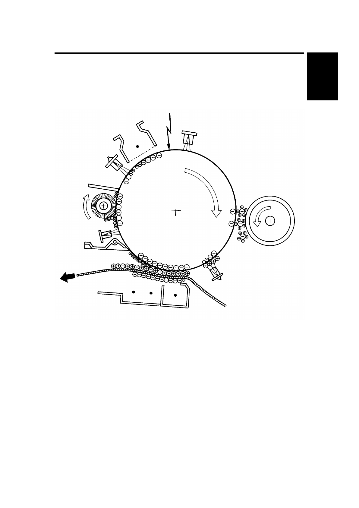
2. COPY PROCESSES AROUND THE DRUM
2. EXPOSURE
1. DRUM CHARGE
3. ERASE
9. QUENCHING
4. DEVELOPMENT
Overall
Information
8. CLEANING
7. PAPER
SEPARATION
5. PRE-TRANSFER LAMP
(PTL)
6. IMAGE TRANSFER
1-5
Page 9

COPY PROCESSES AROUND THE DRUM 1 May 1993
1. DRUM CHARGE
In the dark, the charge corona unit gives a uniform negative charge to the organic
photoconductive (OPC) drum. The charge remains on the surface of the drum because the
OPC drum has a high electrical resistance in the dark.
2. EXPOSURE
An image of the original is reflected to the OPC drum surface via the optics assembly. The
charge on the drum surface is dissipated in direct proportion to the intensity of the reflected
light, thus producing an electrical latent image on the drum surface.
3. ERASE
The erase lamp illuminates the areas of the charged drum surface that will not be used for
the copy image. The resistance of the drum in the illuminated areas drops and the charge on
those areas dissipates.
4. DEVELOPMENT
Positively charged toner is attracted to the negatively charged areas of the drum, thus
developing the latent image. (The positive triboelectric charge is caused by friction between
the carrier and toner particles.)
5. PRE-TRANSFER LAMP (PTL)
The PTL illuminates the drum to remove all negative charge from the exposed areas of the
drum. This prevents the toner particles from being reattracted to the drum surface during
paper separation and makes paper separation easier.
6. IMAGE TRANSFER
Paper is fed to the drum surface at the proper time so as to align the copy paper and the
developed image on the drum surface. Then, a strong negative charge is applied to the back
side of the copy paper, producing an electrical force which pulls the toner particles from the
drum surface to the copy paper. At the same time, the copy paper is electrically attracted to
the drum surface.
7. PAPER SEPARATION
A strong ac corona discharge is applied to the back side of the copy paper, reducing the
negative charge on the copy paper and breaking the electrical attraction between the paper
and the drum. Then, the stiffness of the copy paper causes it to separate from the drum
surface. The pick-off pawls help to separate paper.
8. CLEANING
The cleaning brush removes most of the toner on the drum and loosens the remainder. Then
the cleaning blade scrapes off the loosened toner.
9. QUENCHING
Light from the quenching lamp electrically neutralizes the surface of the drum.
1-6
Page 10
1 May 1993 COPY PROCESS CONTROL
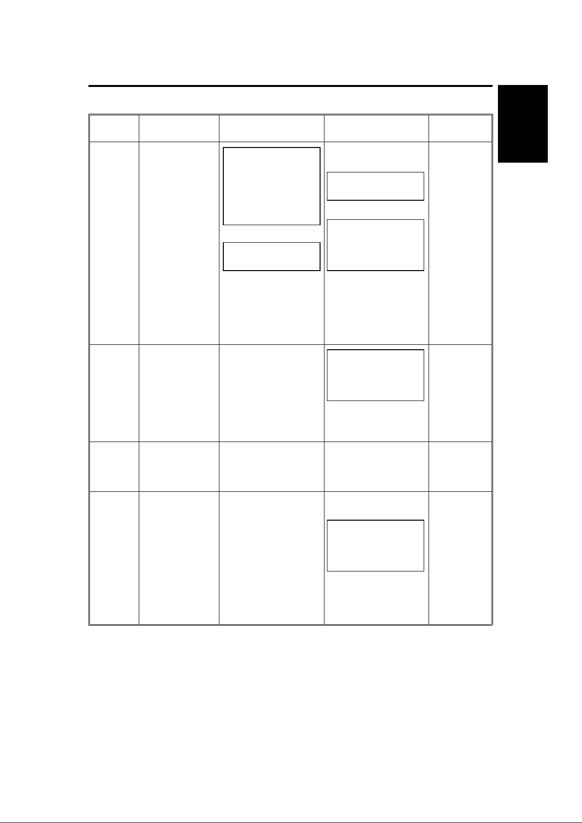
3. COPY PROCESS CONTROL
Image
Density
Control
Toner
Density
Detection
Residual
Voltage
(Vr)
Detection
Between
Copies
(Nonimage
area)
Grid Voltage Exposure Lamp
Voltage
Standard image
density grid
voltage (–920V)
+
Drum residual
voltage (Vr)
correction factor
(SP67) +
Standard ID
sensor grid
voltage (–560V)
+
Vp correction
factor (SP69)
–500 bolts
(Fixed)
0 volt (Fixed) Exposure lamp turns
Base exposure lamp
voltage
1. Manual mode
[SP48]
2. ADS mode [SP48]
and [SP34]
VL correction factor
[SP61] and [SP57]
+
Drum wear correction
factor (SP58)
+
Reproduction ratio
correction factor
Same as image
density control
Same as image
density control
off
Development Bias
Voltage
Base bias voltage
1. Manual mode
2. ADS mode
[SP34]
+
Base bias voltage
adjustment factor
[SP37].....Black
[SP79].....Color
+
Drum residual voltage
(Vr) correction factor
(SP67)
Toner density
adjustment factor
[SP33].....Black
[SP75].....Color
+
Vd correction factor
(Black only) (SP64)
0 volt (Fixed) Full erase
–200 volts (Fixed)
+
Base bias voltage
adjustment factor
[SP37].....Black
[SP79].....Color
Erase Lamp
Depending
on paper
size and
reproduction
ratio
ID sensor
pattern
erase (Vsg
detection:
Full erase)
(All LEDs
ON)
Full erase
(All LEDs
ON)
Overall
Information
+
Drum residual voltage
(Vr) correction factor
(SP67)
NOTE: a) Boxed items can be adju ste d by SP modes surrounded by square
brackets [ ].
b) Data which determines the correct ion factor can be observed by
SP modes surrounded by parenth esis ( ).
1-7
Page 11
MECHANICAL COMPONENT LAYOUT 1 May 1993
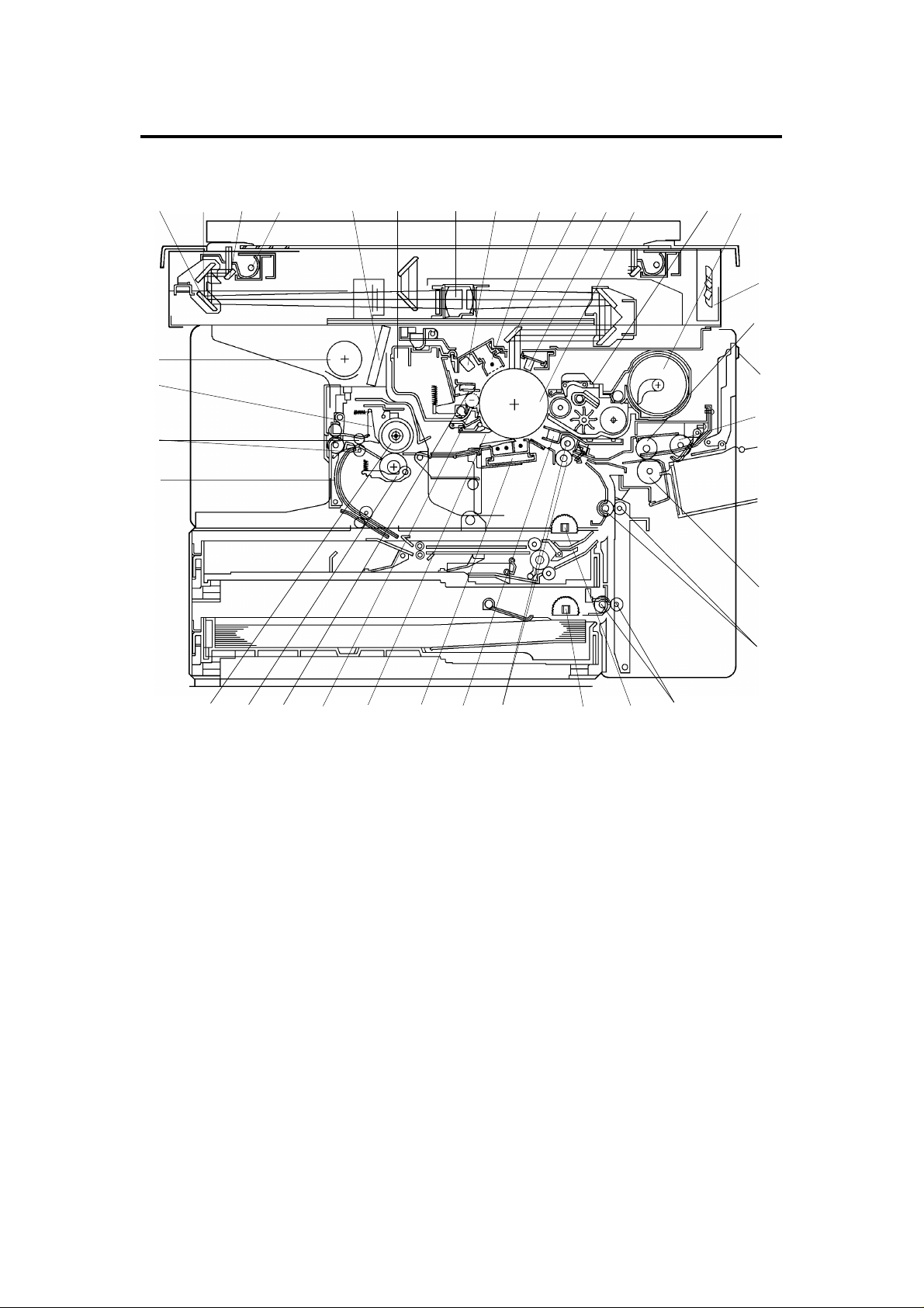
4. MECHANICAL COMPONENT LAYOUT
1 2 3 4 5 6 7 8 9 10 11 12 13 14
35
34
33
32
15
16
17
18
31
1. Third Mirror
2. Second Mirror
3. First Mirror
4. Exposure Lamp
5. Ozone Filter
6. Cleaning Unit
7. Lens
8. Quenching Lamp (QL)
9. Charge Corona Unit
10. Sixth Mirror
11. Erase Lamp
12. OPC Drum
13. Development Unit
14. Toner Supply Unit
15. Optics Cooling Fans
16. 1st Feed Roller
17. Manual Feed Table
18. Pick-up Roller
222324252627282930
19. Separation Roller
20. 1st Relay Rollers
21. 2nd Relay Rollers (A111 copier only)
22. 2nd Feed Rollers (Semi-circular)
23. 3rd Feed Rollers (Semi-circular)
(A111 copier only)
24. Registration Rollers
25. Pre-transfer Lamp (PTL)
26. Transfer and Separation Corona Unit
27. Pick-off Pawls
28. Cleaning Brush
29. Cleaning Blade
30. Pressure Roller
31. Hot Roller
32. Duplex Turn Guide (Option)
33. Exit Rollers
34. Hot Roller Strippers
35. Exhaust Blower
21
19
20
1-8
Page 12
G20
G1
G6
G7
G9
G4
G12
G13
G29: Duplex
Transport
Gear (Option)
1 May 1993 DRIVE LAYOUT
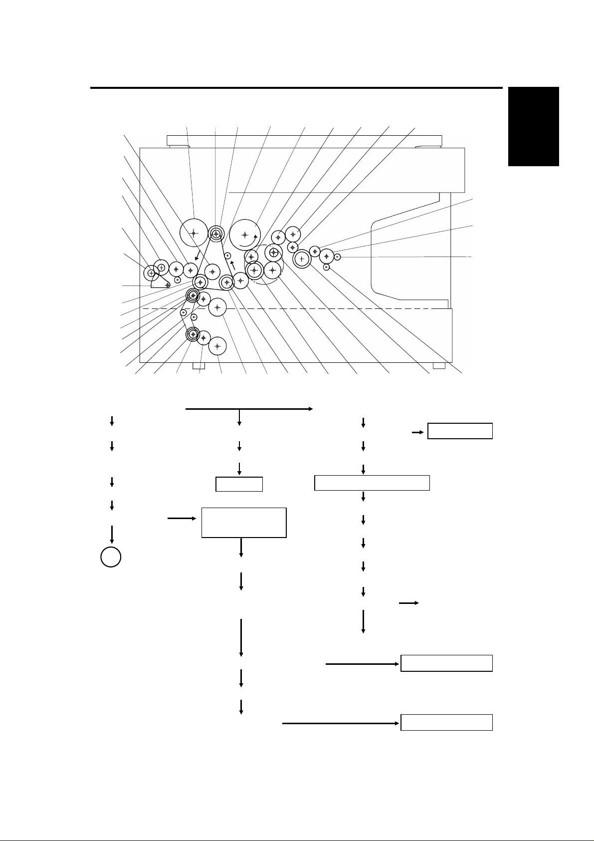
5. DRIVE LAYOUT
G11
G5
G17 BP2 G16 TB1 G19 G18 G22 G23 G24
G26
G27
Overall
Information
G8
G10
BP3
BP4
G14
G1: Main Motor Gear
G2: Relay Gear G18: Relay Gear
Gear
BP1: Timing Belt Pulley
TB1: Timing Belt
TB2
BP5
Drum Fusing and Exit Section
Development
Section
G28
G3BP1G15G33G32G31
G2
G20: Relay Gear
G21: Cleaning Drive Cleaning
G22: Relay GearG19: Drum Drive GearG3: Timing Belt Drive
G23: Relay Gear
G24: Relay Gear
G29G25G21
A
BP2: Timing Belt Pulley
G16: Development
CL Gear
G17: Toner Supply CL Gear
Toner Supply CL Toner Supply Unit
G25: Hot Roller Gear
G26: Relay Gear
G27: Relay Gear
G28: Exit Roller Gear
Development UnitDevelopment CL Solenoid
1-9
Page 13
TB2: Timing Belt
G32: Relay Gear
DRIVE LAYOUT 1 May 1993
A
Paper Feed Section
BP3: Timing Belt Pulley
G11: Registration CL
Gear
Registration CL
Registration Roller
1st Feed Station
1st Paper Feed CL Solenoid
1st Paper Feed Rollers
G4: Relay Gear G12: Relay Roller CL Gear
G5: Relay Gear
G6: 1st Paper Feed CL Gear
G7: Relay Gear
G8: Paper Lift CL Gear
Paper Lift CL
G9: Paper Lift Gear
G10: Sector Gear
2nd Feed Station Upper Relay Roller
G13: Upper Relay
Roller Gear
Relay Roller CL
3rd Feed Station
(A111 copier only)
G14: Relay Gear
G15: 2nd Paper Feed
CL Gear
2nd Paper Feed CL
2nd Paper Feed Roller
1-10
BP4: Timing Belt Pulley
BP5: Timing Belt Pulley
Lower Relay Roller
G31: Lower Relay Roller Gear
G33: 3rd Paper Feed CL Gear
3rd Paper Feed CL
3rd Paper Feed Roller
Page 14
234
18
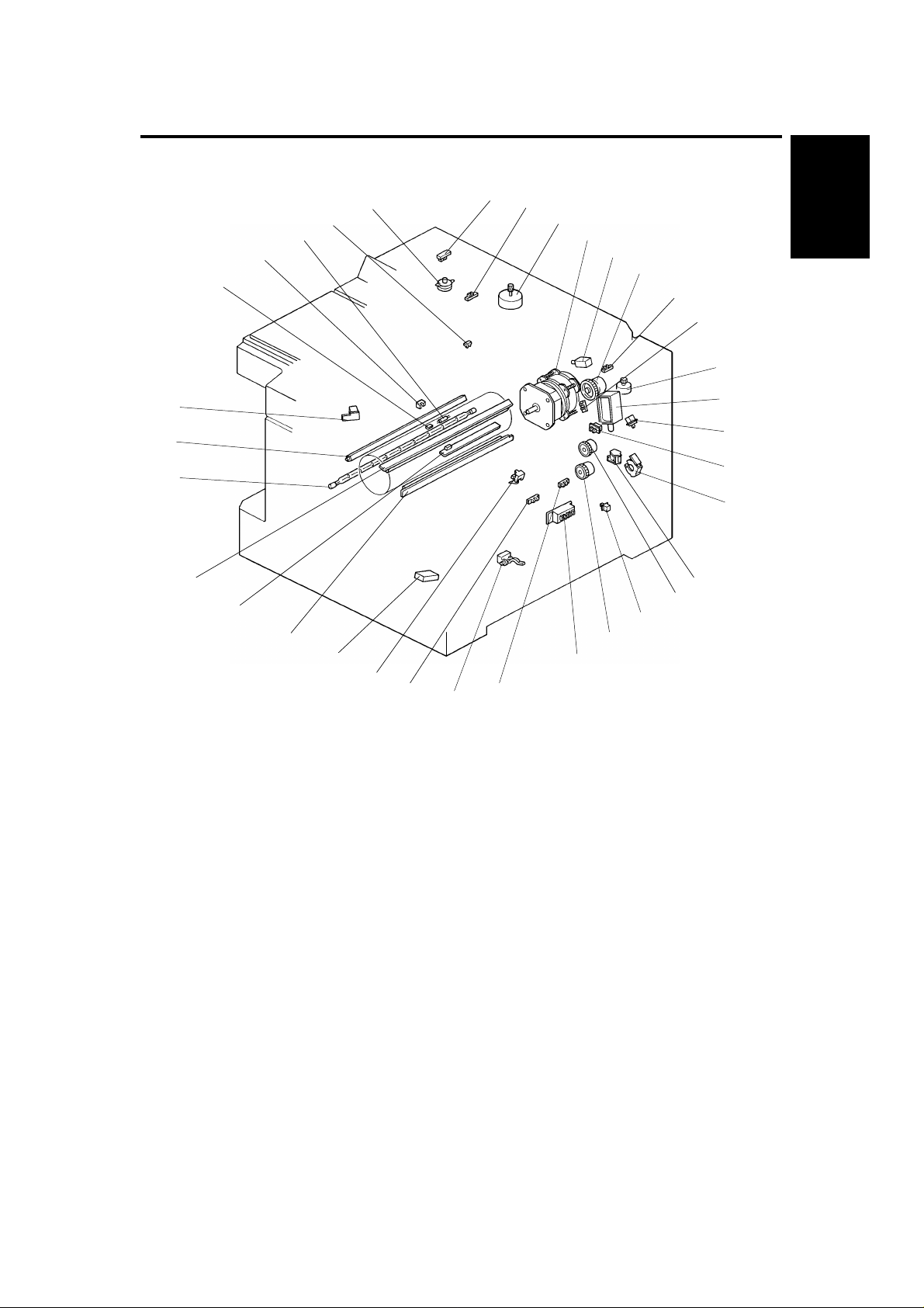
1 May 1993 ELECTRICAL COMPONENT LAYOUT
6. ELECTRICAL COMPONENT LAYOUT
32
31
30
29
28
27
26
25
24
33
23
34
22
21
20
1
19
5
17
Overall
Information
6
7
8
9
10
11
12
13
14
15
16
1. Scanner H.P. Sensor
2. Lens H.P. Sensor
3. Scanner Motor
4. Main Motor
5. Development Clutch Solenoid
6. Toner Supply Clutch
7. 4th/5th Mirror H.P. Sensor
8. Color Toner End Sensor
9. 4th/5th Mirror Motor
10. Pick-up Roller Release Solenoid
11. Manual Feed Table Switch
12. Color Switch
13. Paper Lift Clutch
14. 1st Paper Feed Clutch Solenoid
15. Registration Clutch
16. Right Cover Switch
17. Relay Roller Clutch
18. 1st Paper Size Switch
19. 1st Paper End Sensor
20. Relay Sensor (A111 copier only)
21. Paper Lift Sensor
22. Registration Sensor
23. Total Counter
24. Pre-transfer Lamp (PTL)
25. ID Sensor Board
26. Erase Lamp
27. Fusing Lamp
28. Quenchi ng Lamp (QL)
29. Auto Image Density Sensor
30. Fusing Thermistor
31. Toner Overflow Sensor
32. Fusing Thermofuse
33. Exit Sensor
34. Lens Motor
1-11
Page 15
36
37
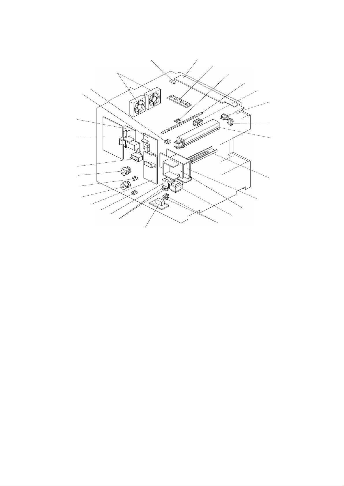
ELECTRICAL COMPONENT LAYOUT 1 May 1993
62
61
60
35
38
39
40
41
59
58
42
43
57
56
44
55
54
53
52
51
50
47
48
45
46
49
35. Platen Cover Closed Switch
(A111 copier only)
36. Operation Panel Board
37. Original Length Sensor
(A111 copier only)
38. Optics Thermoswitch
39. Exposure Lamp
40. Original Width Sensor
(A111 copier only)
41. Cover Safety Switch
42. Main Switch
43. Exhaust Blower Motor
44. Drum Anti-condensation Heater
45. Main DC Power Supply Board
46. Option DC Power Sup ply Bo ard
(A110 copier only)
47. Option Transformer
(A110 copier only)
48. 3rd Paper Size Switches
(A111 copier only)
49. Noise Filter Board
(220/230/240 V only)
50. 2nd Paper Size Switches
51. Main Transformer
52. 3rd Paper End Sensor
(A111 copier only)
53. AC Drive Board
54. 3rd Paper Feed Clutch
(A111 copier only)
55. 2nd Paper End Sensor
56. 2nd Paper Feed Clutch
57. Main Motor Capacitor
58. Main Board
59. TC/SC Power Pack
60. CC/Grid/Bias Power Pack
61. Platen Cover Position Sen sor
(A111 copier only)
62. Optics Cooling Fan Motors
1-12
Page 16

1 May 1993 ELECTRICAL COMPONENT DESCRIPTIONS
7. ELECTRICAL COMPONENT DESCRIPTIONS
Symbol Name Function Index No.
Motors
M1 Main Motor Drives all the main unit components except
for the optics unit and fans.
(115/220/230/240 Vac)
M2 Scanner Motor Drives the scanners (1st and 2nd). (dc
stepper)
M3 Lens Motor Moves the lens position according to the
selected magnification. (dc stepper)
M4 4th/5th Mirror Motor Move the 4th/5th mirror position according to
the selected magnification. (dc stepper)
M5 Optics Cooling Fan
Motor-1
M6 Optics Cooling Fan
Motor-2
M7 Exhaust Blower
Motor
Prevents built up of hot air in the optics
cavity. (24 Vdc)
Prevents built up of hot air in the optics
cavity. (24 Vdc)
Removes heat from around the fusing unit
and blower the ozone built up around the
charge section to the ozone filter.
(115/220/230/240 Vac)
4
3
34
9
62
62
43
Overall
Information
Magnetic Clutch
MC1 Toner Supply Clutch Drives the toner supply roller. 6
Magnetic Spring Clutches
MSC1 2nd Paper Feed
Clutch
MSC2 Paper Lift Clutch Lifts paper to the appropriate feed station. 13
MSC3 Registration Clutch Drives the registration rollers. 15
MSC4 Relay Roller Clutch Drives the relay rollers for the 2nd or 3rd
MSC5 3rd Paper Feed
Clutch
Solenoids
SOL1 1st Paper Feed
Clutch Solenoid
SOL2 Pick-up Roller
Release Solenoid
SOL3 Development
Clutch Solenoid
Starts paper feed from the 2nd paper feed
station.
paper feed station.
Starts paper feed from the 3rd paper feed
station. (A111 copier only)
Starts paper feed from the first paper station. 14
a) After the paper is fed, releases the
pick-up roller from next paper.
b) When the manual feed table is used,
releases the pick-up roller from the table.
Drives the development unit. 5
56
17
54
10
1-13
Page 17

ELECTRICAL COMPONENT DESCRIPTIONS 1 May 1993
Symbol Name Function Index No.
Switches
SW1 Main Switch Supplies power to the copier. 42
SW2 Cover Safety Switch Cuts the ac power line when the front cover
or/and exit cover is open.
SW3 1st Paper Size
Switch
SW4 2nd Paper Size
Switch-1 (Upper)
SW5 2nd Paper Size
Switch-2 (Lower)
SW6 Color Switch Determines which color development unit is
SW7 Manual Feed Table
Switch
SW8 Right Cover Switch Detects when the right cover is open. 16
SW9 3rd Paper Size
Switch-1 (Upper)
SW10 3rd Paper Size
Switch-2 (Lower)
SW11 Platen Cover
Closed Switch
Determines what size paper is in the
cassette.
Determines what size paper is in the upper
paper tray.
Determines what size paper is in the upper
paper tray.
installed.
Detects when the manual feed table is open. 11
Determines what size paper is in the lower
tray. (A111 copier only)
Determines what size paper is in the lower
tray. (A111 copier only)
Detects when the platen cover or the
document feeder is closed.
(A111 copier only)
41
18
50
50
12
48
48
35
Sensors
S1 Scanner Home
Position Sensor
S2 Lens Home
Position Sensor
S3 4th/5th Mirror Home
Position Sensor
S4 Registration Sensor Detects misfeeds. 22
S5 Exit Sensor Detects misfeeds. 33
S6 1st Paper End
Sensor
S7 2nd Paper End
Sensor
S8 Color Toner End
Sensor
S9 Paper Lift Sensor Detects the correct feed height of the
S10 Image Density (ID)
Sensor
Informs the CPU when the 1st scanner is at
the home position.
Informs the CPU when the lens is at the
home position (full size position).
Informs the CPU when the 4th/5th mirrors
assembly is at the home position (full size
position).
Informs CPU when the cassette runs out of
paper.
Informs CPU when the upper paper tray
runs out of paper.
Detects when it is time to add toner for the
color development unit.
cassette.
Detects the density of the image on the
drum to control the toner density.
1
2
7
19
55
8
21
25
1-14
Page 18

1 May 1993 ELECTRICAL COMPONENT DESCRIPTIONS
Symbol Name Function Index No.
S11 Auto Image Density
Sensor (ADS)
S12 3rd Paper End
Sensor
S13 Relay Sensor Detects misfeeds. (A111 copier only) 20
S14 Platen Cover
Position Sensor
S15 Original Width
Sensor
S16 Original Length
Sensor
S17 Toner Overflow
Sensor
Printed Circuit Boards
PCB1 Main Board Controls all copier functions both directly
PCB2 AC Drive Board Drives all ac motors, the exposure lamp,
PCB3 Main DC Power
Supply Board
PCB4 Operation Panel
Board
PCB5 Noise Filter Board Removes the electrical noise.
PCB6 Option DC Power
Supply Board
Senses the background density of the
original.
Informs CPU when the lower paper tray runs
out of paper. (A111 copier only)
Detects when the platen cover is positioned
about 10 cm (4") above the exposure glass.
(A111 copier only)
Detects the original width. (A111 copier
only)
Detects the original length.
(A111 copier only)
Detects when the used toner tank is full. 31
and through the other PCBs.
fusing lamp, quenching lamp, exhaust
blower motor.
Rectifies 26 (31) Vac and 10 Vac input and
outputs dc voltages.
Informs the CPU of the selected modes and
displays the situations on the panel.
(220/230/240 V only)
Rectifies 26 and 10 Vac input and outputs
dc voltages. This board is required when the
document feeder or/and duplex unit is
installed. (A110 copier only)
29
52
61
40
37
58
53
45
36
49
46
Overall
Information
Lamps
L1 Exposure Lamp Applies high intensity light to the original for
exposure.
L2 Fusing Lamp Provides heat to the hot roller. 27
L3 Quenching Lamp Neutralizes any charge remaining on the
drum surface after cleaning.
L4 Erase Lamp Discharge the drum outside of the image
area. Provides leading/trailing edge, side
and editing erases.
L5 Pre-transfer Lamp Reduces charge on the drum surface before
transfer.
1-15
39
28
26
24
Page 19

ELECTRICAL COMPONENT DESCRIPTIONS 1 May 1993
Symbol Name Function Index No.
Power Packs
P1 CC/Grid/Bias
Power Pack
P2 TC/SC Power Pack Provides high voltage for the transfer and
Heaters
H1 Drum
Anti-condensation
Heater
H2 Optics
Anti-condensation
Heater (Option)
Counters
CO1 Total Counter Keeps track of the total number of copies
CO2 Key Counter
(Option)
Provides high voltage for the charge corona,
grid, and the development roller bias.
separation corona.
Prevents moisture around the drum. 44
Prevents moisture from forming on the
optics.
made.
Used for control of authorized use. Copier
will not operate until installed.
60
59
N/A
23
N/A
Transformer
TR1 Main Transformer Steps down the wall voltage to 26 (31) Vac
and 10 Vac.
TR2 Option Transformer Steps down the wall voltage to 26 Vac and
10 Vac. This transformer is required when
the document feeder or/and duplex unit is
installed. (A110 copier only)
Others
TH Fusing Thermistor Monitors the fusing temperature. 30
TF Fusing Thermofuse Provides back-up overheat protection in the
fusing unit.
TS Optics
Thermoswitch
C Main Motor
Capacitor
Provides back-up overheat protection
around the exposure lamp.
Start capacitor 57
51
47
32
38
1-16
Page 20
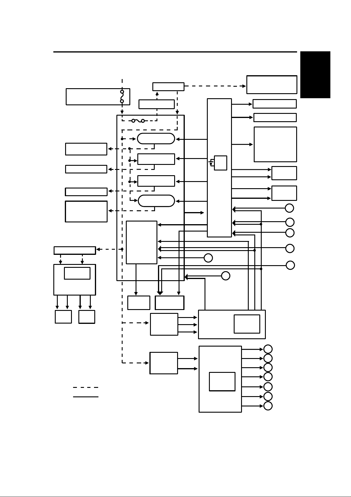
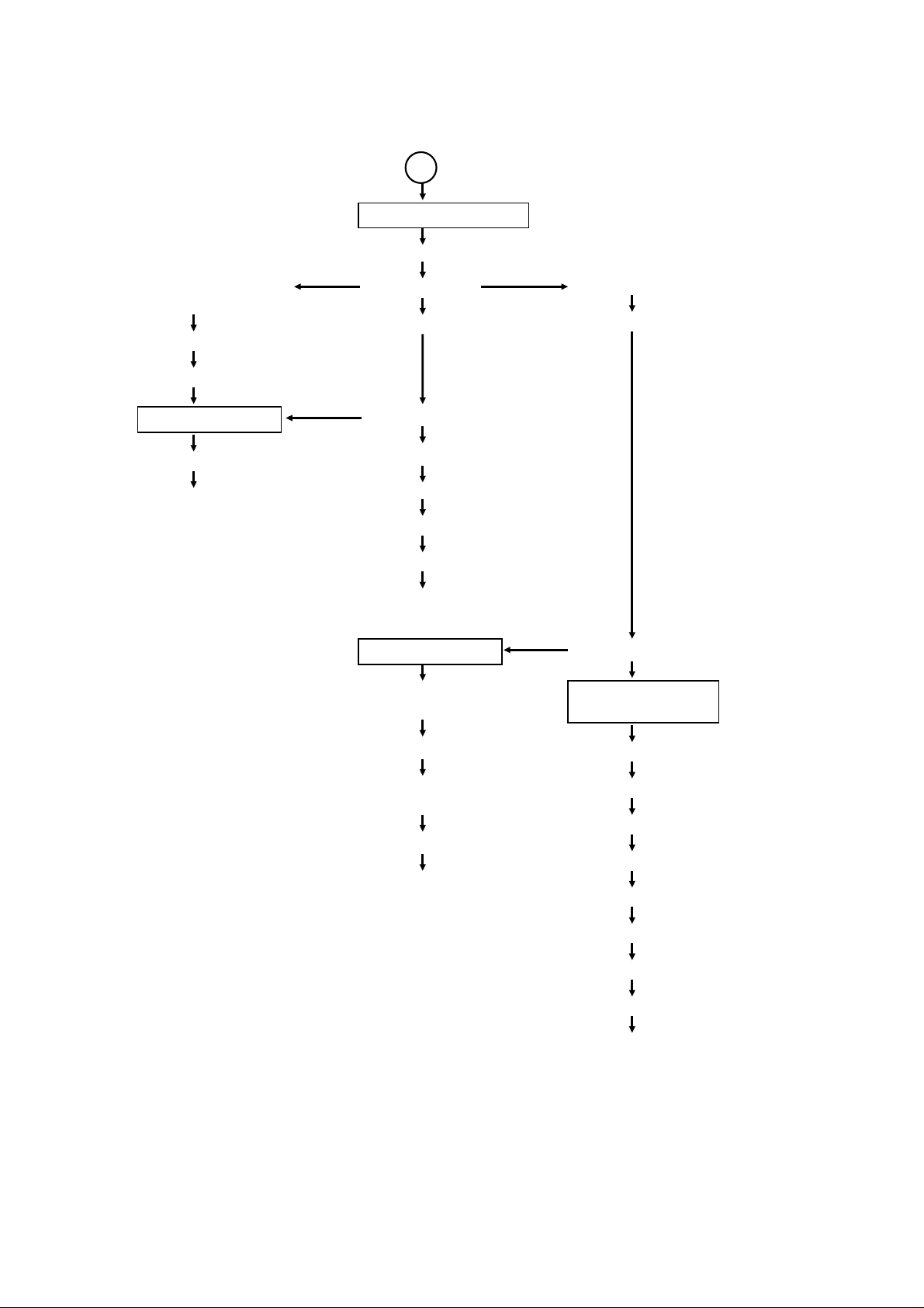
1 May 1993 AC POWER AND DC POWER DISTRIBUTION
8. AC POWER AND DC POWER DISTRIBUTION
Noise Filter Board
(220/230/240V only)
Exhaust Blower
Fusing Lamp
Exposure Lamp
Main Motor
Quenching Lamp
Exhaust Blower
Motor (H)
Optional Transformer
26V AC 10V AC
FU100 (5V)
FU101 (24V)
Optional
DC Power Supply
Board
24V
(VA)5V(VC)
ARDF
AC Power (115V or 220/230/240V)
FU401
Motor (L)
A110 copier
24V
(VA)5V(VC)
Duplex
Cover Safety SW
FU401 (115V only)
Power Relay
(RA401)
Fusing Lamp
Drive Circuit
Exposure Lamp
Drive Circuit
Main Motor
Relay (RA402)
AC Drive Board
Scanner Motor
Drive Circuit
30V (VM)
A110
copier
24V (VM)
A111
copier
Scanner
Motor
A110 copier
Main SW
Control
Signal
24V (VA)
Lens
Motor
Main
Transformer
24V (VA)
24V (VA)
24V (VA)
24V (VA)
Zero
Cross
30V (VM)
5V (VC)
24V (VM)
24V (VA)
10VAC
26VAC
26VAC
Control
Signal
Zero Cross
RAM
PCB
Main
Board
F
Main DC Power
Supply Board
G
Anti-condensation Heater
Scan
Signal
5V (VC)
24V (VA)
24V (VA)
5V (VC)
A111 copier
A111 copier
24V (VA)
For Sorter
24V (VA)
5V (VC)
FU100 (5V)
FU101 (24V)
FU102 (30V)
- Drum
- Optics (Option)
Operation Panel Board
Sensors/Switches
Solenoids
Clutches
Power Packs
4th/5th Mirror Motor
Optics Cooling Fan
Motors
Sorter
24V (VA)
5V (VC)
ARDF
Duplex
Overall
Information
C
A
B
D
E
ac power
dc power
A111 copier
Main
Transformer
1-17
10VAC
31VAC
Main DC Power
Supply Board
FU101
(5V, 24V)
24V (VA)
5V (VC)
24V (VA)
5V (VC)
24V (VA)
24V (VM)
Zero
Cross
A
B
C
D
E
F
G
For optional
equipment
Page 21

AC POWER AND DC POWER DISTRIBUTION 1 May 1993
When this copier is plugged in and the main switch is turned off , ac power is
supplied via the ac drive board to the anti-condensation heate r. Whe n the
front cover and/or the exit cove r is open, the cover safety switch complete ly
cuts off power to all ac and dc components. The RAM board has a back up
power supply (dc battery) for the service program mode and misfeed job
recovery.
(A110 copier)
When the main switch is turned on, the ac power sup ply to the
anti-condensation heat er is cut of f an d ac power is supp lied to the ac
drive board. The main and optiona l tran sformers receive wall outlet ac
power through the ac drive board. It outputs 10 volt s ac and 26 volt s ac t o
the main and optional dc power supply boards.
The main dc power supply board converts the 10 volts ac to +5 volts and
a zero cross signal. There are two 26 volts ac inpu ts. The main dc power
supply board converts them to +24 volts an d +30 volts.
The +5 volt and +24 volt currents are supp lied to the cop ier main boa rd
and ac drive board. The +30 volt current is supp lied to th e ac drive board.
The zero cross signal is supplied to the copier main board thro ugh the ac
drive board.
The copier main board supplie s dc powe r to all cop ier dc components
except the scanner motor and lens motor. All sensors a nd switches
operate on +5 volts. All other dc comp on ents including the power relay
(RA401) and the main moto r relay (RA4 02 ) ope rat e on +24 volts. The
copier main board also supplie s the +5 volt an d +24 volt curre nt s to the
sorter.
The ac drive board supplies +3 0 volt s to the scanner motor and +24 volt s
to the lens motor. The +5 volt current is dc power for the ICs on the
scanner motor drive circuit. The main board sends the control signals to
the scanner motor and len s motor through the ac drive board.
The optional dc power supply boa rd sup plie s +5 volts and +24 volts to the
duplex unit and ARDF.
1-18
Page 22

1 May 1993 AC POWER AND DC POWER DISTRIBUTION
(A111 copier)
When the main switch is turned on, the ac power sup ply to the
anti-condensation heat er is cut of f an d ac power is supp lied to the ac
drive board. The main transformer receives wall outlet ac power thro ugh
the ac drive board and outputs 10 volts ac and 31 volts ac to the main dc
power supply board.
The main dc power supply board converts the 10 volts ac input to +5 volts
and a zero cross signal. The dc power supply board converts the 31 volts
ac to +24 volts.
The +5 volt and +24 volt currents are supp lied to the cop ier main boa rd,
ac drive board. The zero cross signal is supplied to th e cop ier main board
through the ac drive boa rd.
The copier main board supplie s dc powe rs to all cop ier dc components
except the scanner motor and lens motor. All sensors a nd switches
operate on +5 volts. All other dc comp on ents including the power relay
(RA401) and the main moto r relay (RA4 02 ) ope rat e on +24 volts.
The copier main board also supplies th e +5 volt and +24 volt currents to
the sorter, ARDF and duplex unit.
Overall
Information
The ac drive board supplies +2 4 volt s to the scanner motor and lens
motor. The +5 volt current is dc power fo r the ICs on th e scan ne r motor
drive circuit. The main board sends the cont rol signals to the scanner
motor and lens motor through the ac drive board .
When the main board receives power, it act ivat es th e power rela y (RA401)
which then supplies ac power to the fusin g lamp drive circuit, and the
exposure lamp drive circuit on the ac drive board. The exhaust blower motor
begins rotating at low speed. The fusing lamp drive circuit receives a trigger
signal from the main board an d the fusing lamp lights. The exp osure lamp
does not turn on until the main boa rd send a trigger pulse to the exp osu re
lamp drive circuit.
When the Start key is pressed, the main bo ard ene rgize s the main mot or
relay (RA402). Then, the main motor and the quenching lamp turn on an d th e
exhaust blower starts rotating at high speed.
When the main switch is turned off, power is cut off to the main board an d to
RA401, and the drum and optional anticondensatio n he aters are turned on.
The exposure lamp and the fusing lamp power lines are complete ly
disconnected from the lin e volt ag e.
1-19
Page 23

SECTION 2
DETAILED SECTION
DESCRIPTIONS
Page 24

1 May 1993 DRUM
1. DRUM
1.1 OPC DRUM CHARACTERISTICS
An OPC has the characteristics of:
1. Being able to accept a high negative electrical charge in the dark. (Th e
electrical resistance of a photocon ductor is high in the absence of light.)
2. Dissipating the electrical charge when exposed to light. (Exposure to light
greatly increases the conduct ivity of a photo con du cto r.)
3. Dissipating an amount of charge in dire ct pro po rtio n to the inte nsity of the
light. That is, where stronger light is directed to the photoconductor
surface, a smaller voltage remains on the OPC.
4. Being less sensitive to changes in tempe r at ure (wh en compared to
selenium F type drums).
5. During the drum’s life, drum residu al volt ag e gra du ally increases and the
photoconductive surface becomes worn. Therefore, some compensation
for these characteristics is required .
Detailed
Descriptions
2-1
Page 25
[G]
[D]
[F]
DRUM 1 May 1993
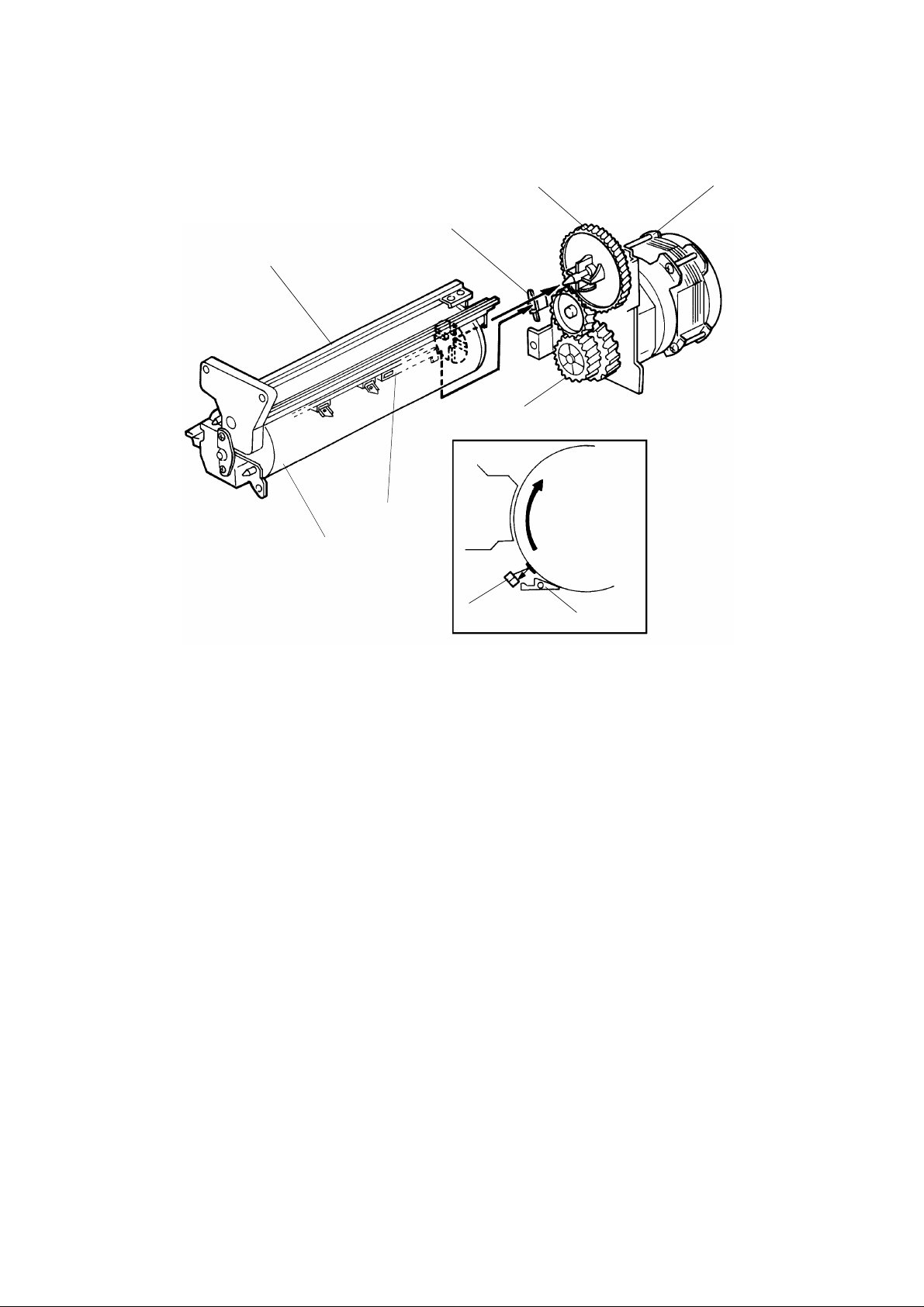
1.2 DRUM UNIT
[E]
[H]
[B]
[C]
[A]
[C]
An organic photoconducto r drum [A] is used on this model.
A drum unit [B] is used to hold the drum to pre ven t stress on the drum. The
drum unit consists of an OPC drum, ID sensor [C] and pick-off pawls [D].
When the drum is replaced, and/or th e pick-o ff pawls an d/ or th e ID sensor
are cleaned, the drum unit must be removed from the copier as a unit.
The drum is driven by the main mo to r [ E] through the main motor gear [F ], a
relay gear and the drum drive gear [G]. The pick-off pawls are always in
contact with the drum surfa ce. The ID sen sor is electrically connected to the
ID sensor connector [H].
2-2
Page 26
1 May 1993 DRUM CHARGE
2. DRUM CHARGE
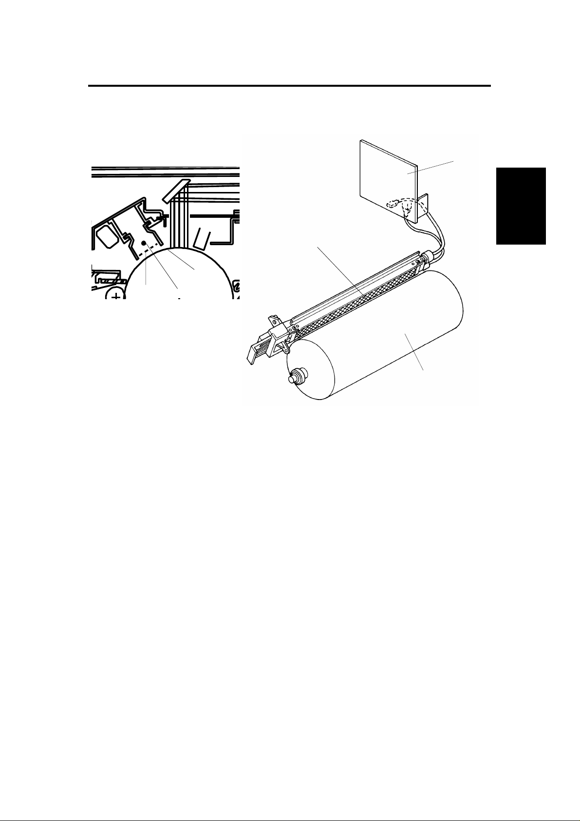
2.1 OVERVIEW
[C]
[D]
[A]
[D] [B]
Detailed
Descriptions
[A]
This copier uses a single wire scorotro n and a hig hly sensitive OPC drum [A].
The corona wire [B] genera tes a corona of negative ions when the
CC/Grid/Bias power pack [C] applies a high voltage. The CC/Grid/Bias power
pack also applies a negative high volta ge to a stainless steel grid plate [D].
This insures that the drum coating receives a uniform negative charg e as it
rotates pa st the corona unit.
The exhaust blower, locat ed abo ve the cop y exit, causes a flow of air from
the upper area of the development unit through the charge corona unit. This
prevents uneven build -up of negative ions that can cau se un even image
density. The exhaust blower runs at half speed when in the stand-by
condition and runs at fu ll sp ee d while copying.
The exhaust blower has an ozone filte r (a ctive carbo ns) which adsorbs ozone
(O3) generated by th e coro na charge. The ozone filter decre ase s in eff icien cy
over time as it adsorbs ozone. The ozone filter should be replaced at every
60,000 copies.
The flow of air around the charge corona wire may deposit paper dust or
toner particles on the corona wire . The se pa rticle s may interfere with
charging and cause low density ba nd s on cop ies. The wire clea ne r clean s
the corona wire when the op erator slides the corona unit in and out.
2-3
Page 27
[C]
DRUM CHARGE 1 May 1993
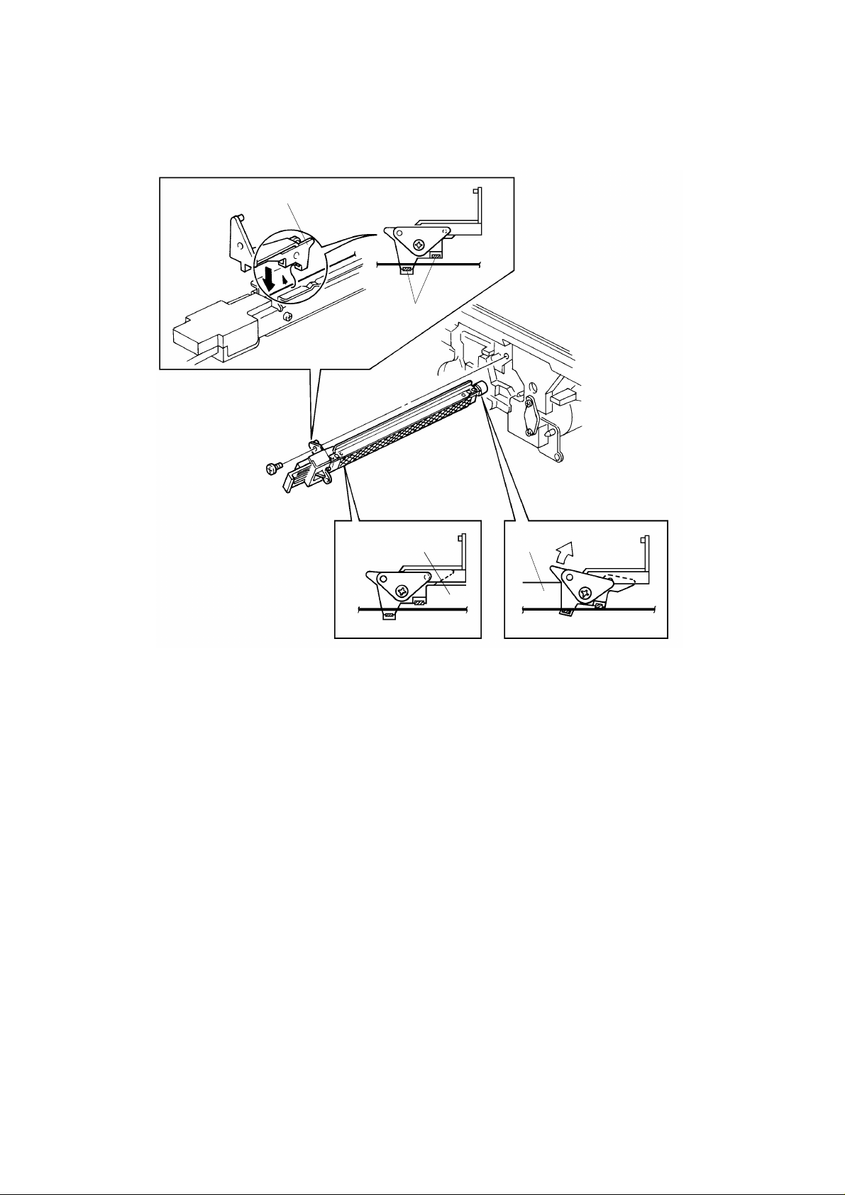
2.2 CHARGE CORONA WIRE CLEANER MECHANISM
[B]
[A]
[D]
Pads [A] above and below th e charge corona wire clean the wire as th e
charge unit is manually slid in and out.
The cleaner pad bracket [B ] rotates when the charge unit is fully e xte nd ed
and the bracket is pulled up against the rear block [C]. This moves the pads
against the corona wire (see illustra tio n). If the charge unit is not fully
extended, the pads do not tou ch th e corona wire.
The pads move away from the wire when the charg e unit is f ully inse rted and
the cleaning bracket is pushed against the front block [D].
After copier installatio n the key operator should be instructe d ho w to use this
mechanism when copies have whit e stre aks.
2-4
Page 28
1 May 1993 DRUM CHARGE
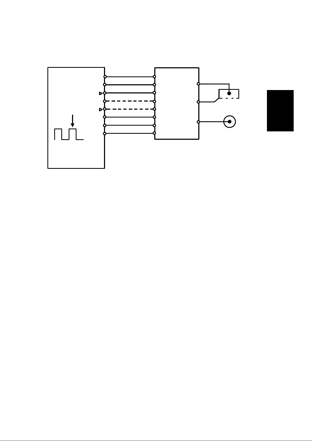
2.3 CHARGE CORONA CIRCUIT
VA [24]
VC [5]
CC Trig [▼24]
Grid Trig (PWM) [▲0→0/5]
Not Used
GND [0]
CN112-8
CN112-7
CN112-6
CN112-5
CN112-4
CN112-3
CN112-2
CN112-1
CN1-1
CN1-2
CN1-3
CN1-4
CN1-5
CN1-6
CN1-7
CN1-8
CC/Grid/Bias
Power Pack
(P1)
M
Charge
Corona Wire
G
Grid
Development
B
Roller
Main Board (PCB 1)
The main board supplies +24 volt s to th e CC/G rid/Bias power pack at CN1-1
as the power supply source. After the Start key is pressed, the CPU drops
CN1-3 from +24 volts to 0 volts. This energizes the charge coron a circuit
within the CC/Grid/Bias power pack, which applies a high nega tive volta ge of
approximately –5.6 kv to the cha rge corona wire. The corona wire then
generates a negative corona charge.
Detailed
Descriptions
The grid limits the charge voltage to ensu re th at the charge does not fluctuate
and an even charge is applied to the drum surf ace .
The grid trigger pulse applied to CN1-5 is a pulse width modulated signal
(PWM signal). This signal is not only a trigger signal; it also chan ges the
voltage level of the grid. As the width of the pulse ap plie d incre ases, the
voltage of the grid also incre ases.
2-5
Page 29

DRUM CHARGE 1 May 1993
2.4 GRID VOLTAGE CORRECTION
To maintain good copy quality ove r the drum’s life , th e grid volta ge is
changed by the following:
• Drum residual voltage correctio n (Vr corre ctio n)
• Vp correction
2.4.1 Drum Residual Voltage Corre ction (Vr correction)
During the drum’s life, the dru m may fat igu e electrically and residual voltage
(Vr) on the drum may gradually increase. When this happens, the corona
charged voltage on th e dru m is not disch arged enough in the quenching an d
exposure processes. Even if the development bia s is applie d in th e
development process, the background area of th e orig inal on the drum may
attract some toner. This may cause dirty background on copies. The Vr
correction prevents this ph enomenon as follows:
A pattern (Vr pattern) is develope d on the drum eve ry 100 0 cop ies and its
reflectivity is detected by the ID sen sor to measu re th e resid ua l volta ge . This
is called residual voltage detect ion . If the reflectivity is low, the residual
voltage will be high.) When the Vr pattern is developed, all blocks of the
erase lamp turn on, the grid voltage is –500 volts and the development bias
voltage is 0 volt.
The CPU determines what level of Vr co rrect ion is necessa ry dep en din g on
the output (Vr ratio [L]) from the ID sensor.
Vrp
L =
x 100(%)
Vsg
Vrp: ID sensor output for Vr pattern
Vsg: ID sensor output for bare drum
The current Vr ratio is disp laye d by SP67.
The CPU increases the development bias voltage depending on the Vr ratio
to prevent dirty backgrou nd on copies. (See page 2-33 for more informatio n. )
The CPU also increases the grid volta ge to ensure prop er imag e de nsit y
depending on the Vr ratio. (See page 2-8.)
2-6
Page 30

1 May 1993 DRUM CHARGE
2.4.2 Vp Correction
Due to the OPC drum’s characteristics, the chargeability of the
photoconductor may decrease until around 2,000 copies after installation. It
will stay stable after 2,000 copies. This charact erist ic e spe cially affe cts
developing of the ID sensor pattern. The ID senso r pat tern developed on the
drum becomes lighter afte r 2,0 00 copie s causin g higher toner concentratio n
in the developer. Vp correctio n is ma de to pre ven t this phenomenon and is
as follows:
The CPU keeps track of the total numb er of copie s made with th e drum . The
grid voltage for the toner densit y det ection increases by –20 volts after 2, 00 0
copies (see page 2-8). The drum counter is displayed by SP69 . The coun ter
must be reset by SP66 when th e drum is replaced with a new one.
Detailed
Descriptions
2-7
Page 31

DRUM CHARGE 1 May 1993
2.5 GRID VOLTAGE CONTROL
The main board controls the grid volt age fo r a copy imag e and th e tone r
density detection through the CC/Grid/B ias po wer pack. As th e grid voltage
for the image density cont rol beco mes less, the copy imag e be come s lighter
and vice versa.
As the grid voltage for the toner densit y det ect ion beco mes less, the toner
concentration in the deve loper becomes higher and vice versa.
The grid voltage is based on the standard grid voltage and the correction
factor as follows:
2.5.1 Image Density Control
Grid Voltage = Standard image density grid voltage (–920 volts [S P60 = 5])
+
Vr correction factor
Vr Correction Factor
L Change of grid voltage
100 to 89 (%)
88 to 76 (%)
75 to 62 (%)
61 to 45 (%)
44 to 0 (%)
±0 (volt)
–40 (volts)
–80 (volts)
–120 (volts)
–160 (volts)
L = Vrp/Vsg x 100 (Vr correction ratio)
Vrp: ID sensor outp ut for Vr corre ction pattern
Vsg: ID sensor output for bare drum
NOTE: The grid voltage for between copies (non-image area) is 0 volt
(Fixed).
2.5.2 Toner Density Detection
Grid Voltage = Standard ID sensor grid volta ge (– 560 volt s [SP 62 = 5])
+
Vp correction factor
Drum counter Vp correction factor
0 to 1,999 (copies)
Over 2,000 (copies)
2.5.3 Vr Detection
Grid Voltage = –500 volts (Fixed)
±0 (volt)
–20 (volts)
2-8
Page 32

1 May 1993 OPTICS
3. OPTICS
3.1 OVERVIEW
[C] [B] [A] [F]
[D] [J] [H]
During the copy cycle, an image of the original is reflecte d onto the drum
surface through the optics assembly as follows.
Light Path:
Exposure Lamp [A] → Original → First Mirror [B] → Second Mirror [C]
→ Third Mirror [D] → Green Color Filter [E] → Lens [F] → Fourth Mirror [G]
→ Fifth Mirror [H] → Sixth Mirror [I] → Drum [J]
[I]
[G]
[K][E]
Detailed
Descriptions
The two optics cooling fans [K] dra w cool air into the optics cavity. The air
flows from the right to the left in the optics cavity and exhausts through the
vents in the left cover. These fans operate during the copy cycle.
This copier has six standard reprod uct ion ratios: Three reduction ra tio s, two
enlargement rat ios, and full size. It also has a zoom function. The operator
can change the repr od uction ratio in one percent st eps f rom 50 % to 200 %.
Stepper motors are used to cha nge th e positio ns of the le ns and mirrors.
Separate motors a re use d be cause the wide range of repro du ctio n ratios
makes it mechanically difficult fo r one moto r t o positio n bo th the lens and
mirrors. A stepper motor is also used to drive th e scanner. This motor
changes the scanner spe ed according to the reproduct ion ra tio .
The thermoswitch opens at 140°C and removes ac power to th e exp osure
lamp to prevent overh eating. The thermoswitch can be reset manually when
the exposure lamp area cools.
A green color filter [E] is loca te d just in front of the lens to decre ase the
sensitivity of the OPC layer against red right.
2-9
Page 33

OPTICS 1 May 1993
3.2 SCANNER DRIVE
[D]
[B]
[E]
[F]
[C]
[A]
[G]
3.2.1 1st and 2nd Scanner Drive Mechanis m
This model uses a stepping moto r [A] to drive the scanners. Both ends of
each scanner are driven to pre vent skewing. The scanners have sliders [B],
which ride on guide rails.
The scanner home position is detected by the home positio n sensor [C]. The
scanner return position is determine d by cou nt ing the scanner motor drive
pulses.
The first scanner [D], which consist s of the exp osure lamp and the first mirror,
is connected to the scanner drive wire by the wire clamps [E]. The second
scanner [F], which consists of th e seco nd and third mirro rs, is conn ect ed to
the scanner drive wire by movable pulleys (th e second scanner pulley [G]).
The pulley moves the second scanne r at ha lf th e velo city of the first scanner.
This is to maintain the focal distance between the original and the lens during
scanning. This relationship can be expressed as:
V1r = 2 (V2r) = VD/r
where r = Reproduction ratio
V1r = First scanner velocity (when the reproduction ra tio
is "r")
V2r = Second scanner velocity (when the reprod uct ion ratio
is "r")
VD = Drum peripheral velocity (120 mm/s)
2-10
Page 34

: Reduction
: Enlargement
1 May 1993 OPTICS
3.3 LENS DRIVE
[C]
[D]
[E]
Detailed
Descriptions
[B]
[F]
[G]
[A]
3.3.1 Lens Drive
The lens motor [A] (stepper motor) changes the lens [B] position through the
lens drive wire [C] in accordance with the selected reproduction ratio to
provide the proper optical distan ce between the lens and the drum surface.
The rotation of th e len s drive pu lley moves the lens back and forth in discrete
steps. The home position of th e lens is dete cte d by th e home position sensor
[D]. The main board keeps track of the lens position base d on the numb er of
pulses sent to the lens mo to r.
3.3.2 Shading Mechanism
The shading plate s [E] are installed on the lens housin g [F] and are slid op en
and shut by the groove cams [G]. When the lens move s in the redu ctio n
direction, the groove cams mo ve th e shading plates closer together. The
plate blocks part of the light passing through the lens to keep the intensity of
the light on the drum even.
2-11
Page 35

OPTICS 1 May 1993
3.3.3 Lens Positioning
[A]
[C]
Home Position (100%)
(100% → 141/155%)
[B]
[D]
(141/155% → 71/65%)
(71/65% → 93%)
(93% → 71/65%)
(71/65% → 141/155%)
(141/155% → 122/129%)
(122/129% → 141/155%)
(141/155% → 100%)
(100% → 71/65%)
(71/65% → 100%)
Reduction SideEnlargement Side
The lens home position sensor [A] informs the main board when the lens is at
full size position (home position). The main board de termine s the lens sto p
position in reduction and enlargement modes by counting the number of
steps the motor makes with refe rence to the lens home position. When a new
reproduction ratio is select ed , th e lens [B] moves directly to the selected
magnification position.
The lens home position is registe red each time the lens starts from or passes
through the lens home position sensor. As the len s mo ves fro m t he
enlargement side to th e red uction side, the sensor regist ers the home
position. This occurs when the actu at or plate [C] enters the lens home
position sensor.
A small vibration can be observed when the lens moves through home
position from the red uct ion side to the enlargement side because the lens is
going in the wrong dire ctio n to register the home position. The lens
overshoots the home position by on ly one pulse before going back to register
the home position.
The lens always stops while moving from lef t to rig ht (as viewed from the
front) to minimize the error ca use d by mech an ical pla y in the drive gears [D].
2-12
Page 36

(71/65% → 100%)
1 May 1993 OPTICS
3.4 4TH AND 5TH MIRROR DRIVE
[B]
[A]
Detailed
Descriptions
Home Position (100%)
(100% → 141/155%)
(141/155% → 71/65%)
(71/65% → 93%)
(93% → 71/65%)
(71/65% → 141/155%)
(141/155% → 122/129%)
(122/129% → 100%)
(100% → 71/65%)
3.4.1 Drive
The 4th/5th mirror drive motor (stepper motor) changes the 4th/5th mirror
assembly position through the pinion gears [A] and the rack gear [B] in
accordance with the selected reprodu ctio n ratio to provid e the prope r optical
distance between the lens and drum surf ace .
3.4.2 Positioning
The positioning mechanism is similar to that of lens po sitio ning, as shown in
the above positioning chart. The scanner always stops while moving from
right to left (as viewed from the fron t).
2-13
Page 37

OPTICS 1 May 1993
3.5 ORIGINAL SIZE DETECTION IN PLATEN MODE
(A111 Copier Only)
[C]
[E]
[B]
[G]
[A]
[F]
[D]
An original width sensor [A] and an original length sensor [B] are under the
exposure glass [C]. The origin al widt h sen sor consists of two reflective
photosensors. The original length sensor consists of five reflective
photosensors (four for inch version).
These sensors are used for the origin al size dete ctio n.
When the main switch is on, these senso rs are act ive an d the orig inal size
data is always sent to the main CPU. The CPU checks t he dat a twice in
platen mode for determining th e original size for APS or ARE modes.
The first check is done when th e pla ten cover position sensor [D] or DF
position sensor [E] is actua ted. At this time the plate n cover (or DF) is
lowered to about 10 cm (4") ab ove the expo sure glass. Only the sensors
underneath the original rece ive the reflected light and output a low sign al.
The other sensors out pu t a hig h signal.
The second check is done when th e platen cover (or DF) is closed and the
platen cover closed switch [F] is actuated. The plat en cover close d switch is
a lead switch. A magnet [G] mounte d on the plat en cover (or DF) a ctu at es
the lead switch.
2-14
Page 38

1 May 1993 OPTICS
The CPU compares the second che ck wit h th e first one to judge if the origin al
is present above the sensor or n ot accord ing to the fo llowin g table.
First
data
High High Original exists
High Low No original
Low High
Low Low Original exists
Second
data
Judgement
Displays "Check Paper
Size" indicator
Original
Width
Sensors
S15-2
S15-1
Original Length Sensors
S16-1
S16-2
S16-4
S16-3
S16-5
The CPU finally determines the original size from the above jud gemen ts. The
following table shows how the origina l size is determine d with info rmat ion of
each sensor.
Sensors
Original Size
A3 11" x 17"0000000
B4
—
F4 — 1000011
A4 lengthwise 8
B5 lengthwise 8" x 10" 1 001111
A5 lengthwise
or smaller
A4 sideways 11" x 8
B5 sideways 8
A5 sideways 1 011111
11" x 15"
10" x 14"
81/2" x 14"1000001
1/2" x 11"1000111
5
1/2" x 81/2" or
smaller
1/2"0001111
1/2" x 51/2" 0011111
Original Width
Sensor
S15-1 S15-2 S16-1 S16-2 S16-3 S16-4 S16-5
0000001
1111111
Original Length Sensor
Detailed
Descriptions
0: Original exists 1: No original
NOTE: 1. The inch version machine does not have S16-3.
2. When the original size is A5 lengthwise/5 1/2" x 81/2" or smaller, the
machine cannot dete ct the original size.
When a copy is made with the pla te n cover (DF) open, the CPU uses the
original size data detected when the Start key is p resse d.
When an original is fed to the expo sure glass through the DF, the CPU uses
the original size data from the DF.
2-15
Page 39
OPTICS 1 May 1993
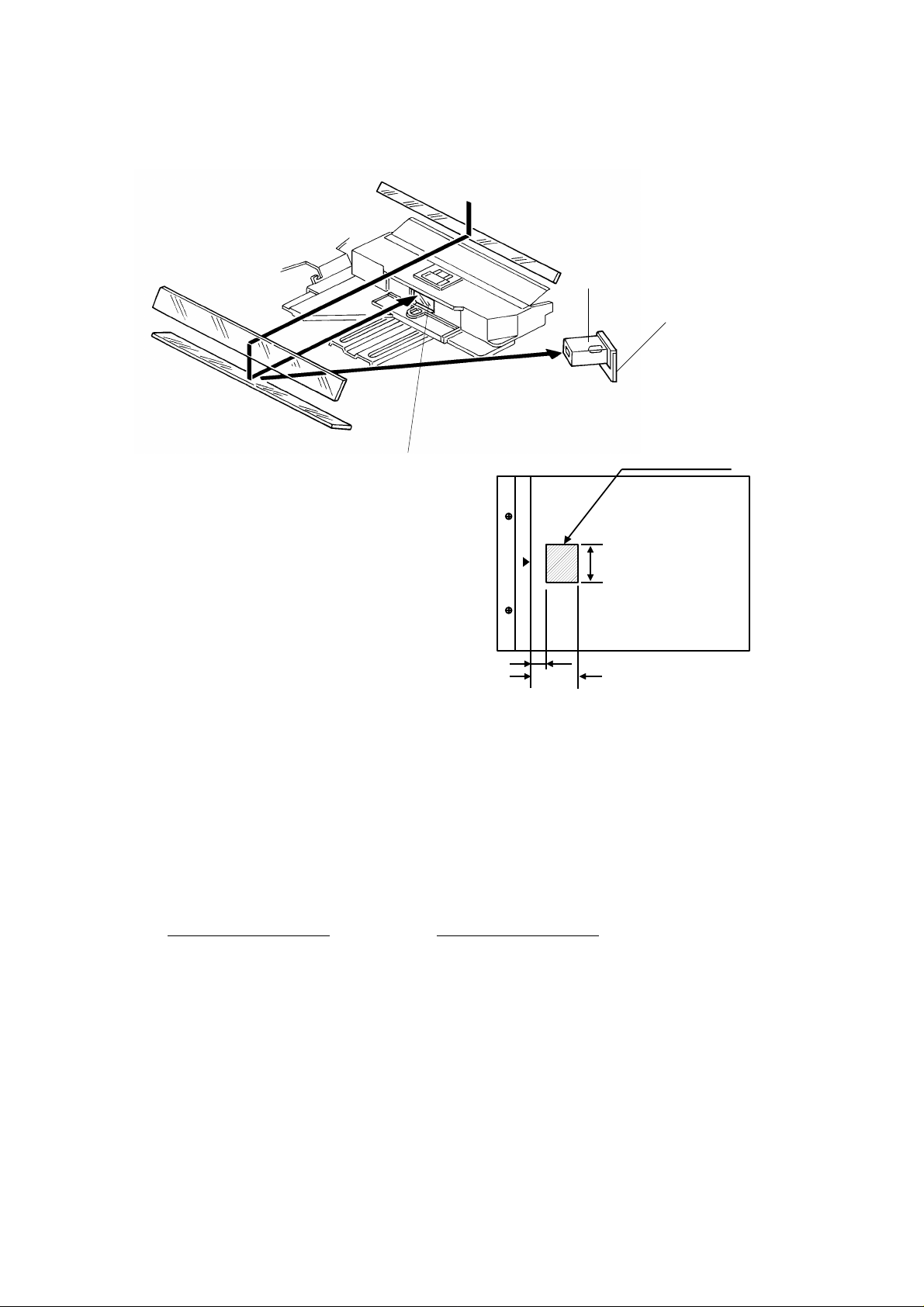
3.6 AUTOMATIC IMAGE DENSITY SENSING
[C]
[B]
[A]
A
Sampled area
70 mm
B
Light from the exposure lamp is refle cted from the original and travels to the
lens [A] via the mirrors. The auto ID senso r [B] , a phot od iod e, is mount ed on
the upper front frame. The senso r cover [C] has a hole in it to allow light to
fall directly onto the sensor. Sampling starts 10 millimete rs from th e leadin g
edge of the original and continues to 50 millimeters from the leadin g edge of
original in full size mode. The length of "A" and "B" will vary depending on the
selected reproduction ratio.
The lengths "A" and "B" in ea ch rep roduction ratio are calculat ed as follows:
A =
Reproduction Ratio (%)
10 mm
x 100 B =
Reproducti on Ratio (%)
50 mm
x 100
The photosensor circuit converts the light intensity to a voltage. The dete cte d
voltage is amplified and sent to the main PCB. The CPU stores the voltage of
each sampled point in RA M. It the n comp utes the image density of the
original from the maximum sample volt ag e an d cha ng es th e de velo pme nt
bias accordingly. (See page 2-3 1 for d eta ils. ) The exposure lamp voltage is
constant regardless of the image density of the origin al.
2-16
Page 40

1 May 1993 OPTICS
3.7 EXPOSURE LAMP VOLTAGE CORRECTION
To maintain good copy qua lity, the exposure lamp voltage is chan ge d by th e
following:
• VL correction
• Drum wear correction
• Reproduction ratio corre ction
3.7.1 VL Correction
The light intensity may decrea se be cause of dust accumulated on th e op tics
parts. This may cause dirty backgrou nd s on cop ies. To compensate for this
phenomenon, VL correction is done as follows:
The CPU keeps track of the amount of time th at the main switch is on. The
exposure lamp voltage incre ase s at set intervals, which can be changed by
SP61 (see page 2-20).
3.7.2 Drum Wear Correction
During the drum’s life, the photoco nd uct ive surf ace of the drum becomes
worn by contact with the cle an ing brush . This affects the drop of the drum
photosensitivity. This may cause dirt y backgrounds on copies.
To compensate for this pheno men on , dru m we ar corre ction is made as
follows:
The CPU keeps track of the dru m rotation time. The exposure lamp volt ag e
increases at set intervals (se e page 2-21 ).
3.7.3 Reproduction Ratio Correction
Detailed
Descriptions
To compensate for the change in the concentration of light on the drum, the
exposure lamp voltage incre ase s dep ending on the selected reproduction
ratio (see page 2-21).
2-17
Page 41

OPTICS 1 May 1993
3.8 EXPOSURE LAMP VOLTAGE CONTROL
The main board controls t he expo sure la mp volt ag e th rough the ac drive
board. The exposure lamp voltage is based on the base lamp volta ge and
various correction factors. The exposure lamp data setting dete rmines the
base lamp voltage. The followin g table gives th e appro ximate lamp voltage
for each data setting.
Exposure Lamp Data/Voltage Reference Table
Exposure lamp voltage
Exposure
lamp data
100 57.1 105.9 126 71.9 133.4
101 57.6 106.9 127 72.5 134.5
102 58.2 108.0 128 73.0 135.5
103 58.8 109.1 129 73.6 136.6
104 59.3 110.1 130 74.2 137.6
105 59.9 111.2 131 74.7 138.7
106 60.5 112.2 132 75.3 139.8
107 61.1 113.3 133 75.9 140.8
108 61.6 114.4 134 76.5 141.9
109 62.2 115.4 135 77.0 142.9
110 62.8 116.5 136 77.6 144.0
111 63.3 117.5 137 78.2 145.1
112 63.9 118.6 138 78.7 146.1
113 64.5 119.6 139 79.3 147.2
114 65.0 120.7 140 79.9 148.2
115 65.6 121.8 141 80.5 149.3
116 66.2 122.8 142 81.0 150.4
117 66.8 123.9 143 81.6 151.4
118 67.3 124.9 144 82.2 152.5
119 67.9 126.0 145 82.7 153.5
120 68.5 127.1 146 83.3 154.6
121 69.0 128.1 147 83.9 155.6
122 69.6 129.2 148 84.4 156.7
123 70.2 130.2 149 85.0 157.8
124 70.8 131.3 150 85.6 158.8
125 71.3 132.4
(standard) Exposure
115V
machine
220/230/240V
machine
lamp data
Exposure lamp voltage
(standard)
115V
machine
220/230/240V
machine
NOTE: Exposure lamp rating: 115 V machine: 97 V/ 28 0 W
220/230/240 V machine: 180 V/310 W
2-18
Page 42

1 May 1993 OPTICS
The method of control is different dependin g on whethe r the ima ge density is
manually selected or the auto image density mode is selected.
The exposure lamp voltage consist s of th e followin g fa cto rs:
Exposure lamp voltage = Base exposure lamp voltage factor
(Manual or auto image density mode )
+
VL correction factor
+
Drum wear correction factor
+
Reproduction ratio correction factor
3.8.1 Base Lamp Voltage Factor in Manual Image Density Mode
Manual ID level 1234567
Exposure lamp data Vo –4 Vo Vo Vo Vo +4 Vo +8 Vo +12
Darker Lighter
Detailed
Descriptions
The above table shows changes in the expo sure la mp data in manual image
density mode.
SP48 sets the exposure lamp data for level 4 (Vo) of manual image density
mode. A value from 100 to 15 0 can be sele cted.
3.8.2 Base Lamp Voltage Factor in Auto Image Densi ty Mode
In auto ID mode, the CPU selects the level 4 (Vo) exposure lamp data
regardless of the input from the auto image density sensor. When the auto
image density level is set to lighter in SP3 4, the expo sure lamp da ta chan ge s
to that of manual ID level 5 as shown below. When the auto image de nsity
level is set to darker, the develo pme nt bias shif ts +40 volts. Only the
development bias varies acco rding to the input from the auto image de nsit y
sensor. (See page 2-31.)
Auto Image Density Level (SP3 4)
Auto image density level SP data (SP34) Exposure lamp data Development bias shift
Normal 0
Darker 1
Lighter 2
Same as level 4
(Vo ±0)
Same as level 4
(Vo ±0)
Same as level 5
(Vo +4)
±0 volts
+40 volts
±0 volts
2-19
Page 43

OPTICS 1 May 1993
3.8.3 VL Correction Factor
SP data (SP61) Change of exposure lamp data/Machine on time
0 +1/70H
1 +1/140H
2 +1/40H
3 +1/20H
4 +1/10H
5 +1/5H
6 No Correction
(Factory Setting: SP61 = 0)
The exposure lamp data increases by +1 at set intervals of the machine on
time. This interval can be changed by SP61 as sho wn in th e above tab le.
The total increase fo r VL correction cannot excee d +20. When cleaning the
optics parts, SP94 shou ld be perf ormed to clear V L correction.
VL correction clear (SP94)
SP data (SP94) VL correction
0 Not clear
1 Clear
NOTE: When "1" is input in SP94, the machine on time (SP5 7) da ta is
cleared.
2-20
Page 44

1 May 1993 OPTICS
3.8.4 Drum Wear Correction Factor
Drum rotation time (SP58) Change of exposure lamp da ta
0 to 24 H
±0
25 to 49 H +1
50 to 74 H +2
75 to 99 H +3
More than 99 H +4
To compensate for OPC drum wea r ca use d by con ta ct with the clean ing
brush, the exposu re lamp dat a incre ases at set interval of drum rotat ion time
as shown in the above table.
The drum rotation time is displayed by SP58. This time must be reset by
SP66 when the drum is replaced with a new one.
3.8.5 Reproduction Ratio Correction Factor
Reproduction ratio Change of exposure lamp dat a
50 to 61% +2
62 to 139%
±0
140 to 159% +2
Detailed
Descriptions
160 to 179% +6
180 to 200% +10
The exposure lamp data increases depending on the selected reproduction
ratio as shown in the above table.
2-21
Page 45

OPTICS 1 May 1993
3.9 EXPOSURE LAMP CONTROL CIRCUIT
To dc power
Main Board (PCB1)
Zero Cross
TP105
(LAMP)
E
Feed back
signal
CPU
+24V
C
24V
0V
Trigger Pulse
B
CN122-8
CN122-5
To dc power
supply board
CN122-4
CN122-7
CN435-1
CN435-4
CN437-4
CN435-5
CN435-2
supply board
CN437-6
VR401
R403
R401
AC Drive Board (PCB2)
ZD
401ZD402
R404
403
ZD
D401
ZD
404
R406
R411
TRC401
R413
R404
C401
PC401
DB401
CR401
L401
L402
TR401
C411
T402
CN419-1
Thermo-SW
(TS)
Exposure
Lamp
(L1)
D
CN419-2
T407
A
AC115V
/220V
/230V
/240V
AC power
Zero cross
Trigger pulse
Lamp power
Feedback
signal
A
B
C
D
E
Feedback
The main board sends lamp trigger pu lses to the ac drive board from
CN122-7. PC401 activat es TRC40 1, which provides ac power to the
exposure lamp, at the trailing edge of each trigger pu lse.
The voltage applied to the expo sure lamp is also provided to the fee db ack
circuit. The feedback circuit steps down (TR401), rectif ies (DB401), and
smoothes (zener diodes and capacitors) the lamp voltage. The CPU monit ors
the lowest point of the smoot he d wave (f eedb ack sign al), which is directly
proportional to the actu al lamp voltage.
The CPU changes the timing of the trigger pulses in response to the
feedback voltage. If the lamp voltage is too low, the CPU sends the trigg er
pulses earlier so that more ac power is applie d to the expo sure lamp. This
feedback control is performed instantly; so, the lamp voltage is always stable
even under fluctuating ac power conditions.
The voltage applied to the expo sure lamp can be changed with SP48 (Light
Intensity Adjustment). The ADS volta ge adju stme nt (S P56) must be done
whenever the light intensity adjustment is done.
2-22
Page 46
Lo
Lc
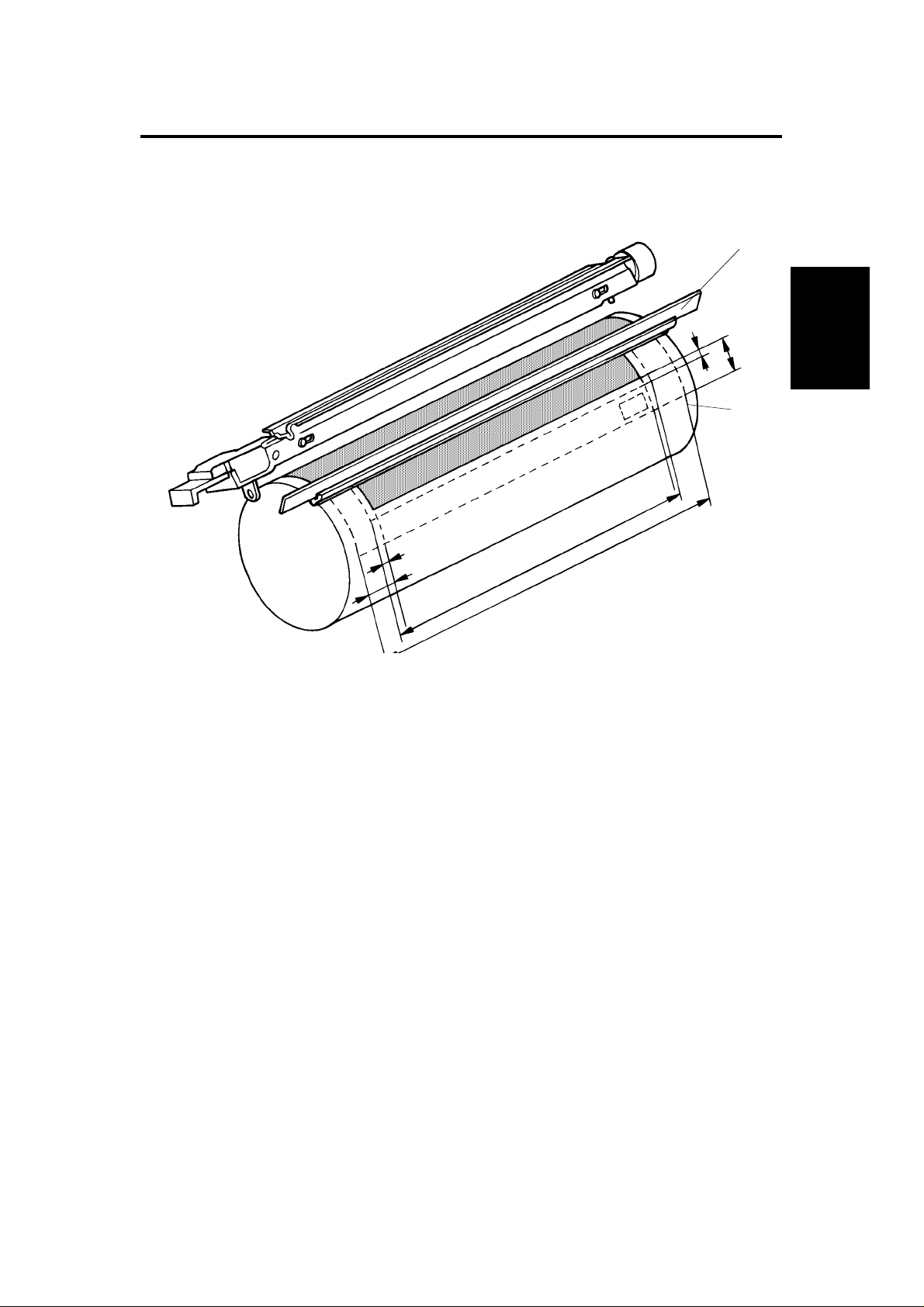
1 May 1993 ERASE
4. ERASE
4.1 OVERVIEW
[A]
LE
EL
[B]
Detailed
Descriptions
SE
ES
LE: Lead edge erase margin 2.5 ±1.5 mm
SE: Side erase margin 2.0 ±2.0 mm on each side;
total of both sides 4 mm or less
LO: Original width
LC: Charged width of drum
EL: Lead edge erase
ES: Side erase
The erase lamp [A] consists of a line of LEDs (4 3 LEDs) extending across the
full width of the drum [B].
The erase lamp has four fu nct ions: lead edge erase, side erase , tra il e dg e
erase and editing mode erase (erase edge or/and erase center). Trail edge
erase begins after the trailing edge of the copy paper; the refore, the trailing
edge of the copy will not be erased.
2-23
Page 47

ERASE 1 May 1993
FrontRear
4.1.1 Lead Edge Erase
The entire line of LEDs turns on when the main mot or tu rns on . The y stay on
until the erase margin slight ly overla ps the lead edge of the original image
area on the drum (Lead Ed ge Erase Ma rgin ). This prevents the toner density
sensor pattern fro m being developed every copy cycle and th e shadow of the
original edge from being deve loped on the paper. At this point , side erase
starts. The width of th e lead edge erase margin can be adjusted using SP41.
During the toner density detection cycle (once every ten copy cycles), a block
of erase lamps (labeled "o" above) turns off long enough for th e sensor
pattern to be developed.
The entire line of LEDs turns on when the re sidu al volt ag e on the OPC dru m
is being detected (V r det ection).
4.1.2 Side Erase
Based on the combinat ion of copy paper size and the reprod uct ion ratio data,
the LEDs turn on in blocks (labeled "a" – "p" above ). This reduces toner
consumption and drum cleaning load.
2-24
Page 48

1 May 1993 ERASE
The following table shows which blocks of erase lamp LEDs turn on
depending on the paper size an d the reproduction ratio :
Blocks ON Paper size Reproduction ratio (%)
None
a 95–98
a–b 91–94
a–c B4, B5 Sideways 87–90
a–d 83–86
a–e 79–82
a–f 8
a–g A4 Lengthwise 70–73
a–h 67–69
a–i 64–66
a–j 61–63
a–k 57–60
a–l 54–56
a–m 52–53
a–n A5 Lengthwise, 5
All (a–p) Lead Edge and Trail Edge Erase/For Vr Detection Cycles
a–n, p For Toner Density Detection Cycles
A3, A4 Sideways, 11" x 17",
11" x 8
1/2", Manual Feed
1/2" x 11", 81/2" x 51/2", F4 74–78
1/2" x 81/2" 50–51
99–200
Detailed
Descriptions
4.1.3 Trail Edge Erase
The entire line of LEDs turns on after the trailing edge of the latent image has
passed. Therefore, a trailing erase margin cannot be observed on the copy.
The LEDs stay on to erase th e leading edge of the lat en t image in the next
copy cycle. After the fin al copy, the erase lamps turn off at th e same time as
the main motor.
4.1.4 Editing Mode Erase
When copying a thick book original, the binding margin at th e cen ter and the
edges may appear dirty on copies. To preve nt this, the erase center mode,
erase edge mode, or erase cent er an d ed ge mode can be selected as follows:
1. Press the Program key.
2. Press one of the following numb ers:
Erase center..................... Press "6"
Erase edge....................... Press "7"
Erase center and edge..... Press "8"
2-25
Page 49

ERASE 1 May 1993
a) Center Erase
The erase margin of the ce nt er is
done through the timing of when
the entire line of LEDs turns on.
The margin can be changed by
SP26 as shown.
b) Lead and Trail Edge Erase
The erase margin of the le ad and
trail edges is done through the
timing of when the entire line of
LEDs turns on. The margin can
be changed by SP18 as shown.
SP data (SP26) Margin of the center
0 20 mm
1 10 mm
2 15 mm
3 25 mm
(Factory setting: SP26 = 0)
SP data (SP18)
0 10 mm
1 5 mm
2 15 mm
3 20 mm
(Factory setting: SP18 = 0)
Margin of the lead and
trail edges
c) Side Edge Erase
The erase margin of the sid e
edges is done through which
blocks of the LEDs turn on. The
margin can be changed by SP 13 .
The margin of the side edge s
depends on the paper size and
reproduction ratio.
The right table show th e margin
of the side edges for the various
paper sizes in the full size copy
mode.
Paper Size
A3, A4, * 13 mm 5.5 mm
11" x 17", 11" x 8.5",
11" x 15"
B4, B5, 10" x 14" 13.5 mm 7.5 mm
8.5" x 14", 8.5" x 13",
8.5" x 11", 8.5" x 5.5"
A4R, A5, 8" x 13",
8" x 10.5", 8" x 10"
B5R, B6 10 mm 5 mm
(Factory setting: SP13 = 0)
* Non-standard paper size
Margin of side edges
SP13 = 0 SP13 = 1
11 mm 3.5 mm
12 mm 6 mm
11 mm 6 mm
2-26
Page 50

1 May 1993 DEVELOPMENT
5. DEVELOPMENT
5.1 OVERVIEW
When the main motor turns on and the deve lopment clutch solenoid is
de-energized, the paddle roller [A] development roller [B] th e au ger [C], and
the agitator [D] start turn ing. The paddle roller picks up developer in its
paddles and transports it to the deve lop ment roller. Internal permanent
magnets in the development roller attract the developer to the development
roller sleeve.
[B]
[E]
[A] [D]
[F][C]
Detailed
Descriptions
The turning sleeve of the deve lopment roller then carries the deve loper past
the doctor blade [E]. The doct or blade trims the developer to the desired
thickness and creates backsp ill to th e cross-mixin g mechanism.
The development roller con tin ue s to tu rn, carrying the deve lop er to the OPC
drum. When the developer bru sh con ta cts th e dru m surface, the negatively
charged areas of the drum surfa ce at tra ct an d hold th e positive ly ch arg ed
toner. In this way, the latent image is developed.
The development roller is given a negat ive bia s to pre ven t toner from being
attracted to non-image area s on the dru m tha t may have residual negative
charge. The bias also contro ls image density.
After turning abou t 10 0 de gre es more, the development roller rele ases the
developer to the deve loper tank. The developer is agita ted by the paddle
roller, agitator [D], an d th e cross-mixin g mechanism.
Rotation of the pad dle roller and development roller tend to cause air
pressure inside the unit to become hig he r tha n the air pre ssure arou nd the
development unit. A hole , fitted with a filter [F], has be en added to th e top of
the unit to relieve air pressure and to minimize toner scattering.
2-27
Page 51

DEVELOPMENT 1 May 1993
5.2 DRIVE MECHANISM
[I]
[E]
[G]
[H]
[J]
[A]
[D]
[B]
[F]
[C]
When the main motor turns, the rota tion is transmitted from the develo pme nt
drive gear [A] to the deve lop ment roller gear [B] throug h th e de velo pment
clutch [C]. (The rotation is transmitted to the development drive gear when
the development soleno id [D] is de-en erg ized.) Then, the rotation is
transmitted from the develo pment roller gear to the paddle roller gear [E ]
through the idle gea r [ F].
A gear [G] on the front end of the paddle roller shaft drives the auger gear [H]
and the agitator gear [I]. The padd le rolle r shaf t ha s a knob [J] on the front
end so that it can be turned man ua lly t o exch an ge deve lop er. The knob has a
one-way clutch inside. The one-wa y clutch prevents the developmen t rolle r
from turning in the wrong direction.
The development clutch solenoid energizes each copy cycle after image
development is completed. This stops the rollers, thereby reducing developer
fatigue.
2-28
Page 52

[E]
1 May 1993 DEVELOPMENT
5.3 CROSS-MIXING
[F]
[D]
[A]
[B]
Detailed
Descriptions
[C]
This copier uses a standard cross-mixing mechanism to keep the toner and
developer evenly mixed . It also he lps ag ita te the developer to prevent
developer clumps from forming and help s create the trib oelectric charge.
The developer on the tu rning development roller is split int o two parts by the
doctor blade [A]. The part tha t stays on the development roller [B] forms the
magnetic brush and develops the latent image on the drum. The part that is
trimmed off by the doctor blade goes to the backspill plate [C].
As the developer slides down the backspill plate to the agit ator [D], the mixing
vanes [E] move it slightly to ward the rear of the unit. Part of the developer
falls into the auger inlet and is transp ort ed to the fro nt of the unit by th e auge r
[F].
The agitator moves th e de velo pe r slig ht ly t o th e fro nt as it turns, so the
developer stays level in th e de velo pment unit.
2-29
Page 53

DEVELOPMENT 1 May 1993
5.4 DEVELOPMENT BIAS FOR IMAGE DENSITY CONTROL
Image density is controlled by changing two items: (1) the strength of the bias
voltage applied to th e de velo pment roller sleeve, and (2) the st ren gt h of the
voltage applied to th e exp osure lamp.
Applying a bias voltage to the development sleeve reduce s the pot en tia l
between the develo pment roller and the drum, thereby reducing the amount
of toner transferred. As the bias voltage beco mes gre at e r, the copy image
becomes lighter. Similarly, incre asing the voltage to the exposure lamp
causes an increase in light intensity which also results in lighter copies.
The method of control is different dependin g on whethe r the ima ge density is
manually selected or the au tomatic ID mode is used.
The development bias ap plie d to the development roller sle eve has th e
following three factors:
Development bias voltage = Base bias voltage factor
(Manual or automatic image density control)
+
Base bias voltage adjustme nt factor
+
Vr correction factor
The base bias voltage for non-image area s (bet wee n cop ies) is – 200 volt s.
The above correction factors are also applied.
5.4.1 Base Bias Voltage Factor in Manual Image Density Control
Darker Lighter
Manual ID level 1 2 3 4 5 6 7
Base bias voltage –120 –120 –160 –200 –200 –240 –280
Exposure lamp data Vo –4 Vo Vo Vo Vo +4 Vo+8 Vo+12
In manual ID control mode, the base bias volt ag e depe nds on th e man ually
selected ID level. The voltag e applied at each ID level is shown in the above
table. The base exposu re lamp voltage also varies dependin g on the ma nu al
ID level as shown in the table. (See pa ge 2-19 for more info rmation.)
2-30
Page 54

1 May 1993 DEVELOPMENT
5.4.2 Base Bias Voltage Factor in Automatic Image Dens ity Contr ol
In automatic image density contro l mo de, th e base exposure lamp voltage is
fixed to Vo. (See page 2-19 for more information.) Image density is controlle d
by changing only the base bias voltage.
The base bias voltage depends on the background image density of the
original, which is measured using the auto ID sen sor. (See page 2-16 for
more information.)
The CPU checks the voltage output from the automa tic ID circuit . This circuit
has a peak hold function. The peak hold voltage corresponds to the
maximum reflectivity of the original. The CPU then determines the proper
base bias level with refere nce to th e pe ak ho ld voltage.
The following table gives th e ba se bias voltages at each ADS output level.
When the automatic density level is set to darker by SP34, the base bias
voltage shifts +40 volts as shown in the following table.
Detailed
Descriptions
K
Base bias voltage
Normal or lighter (SP34 = 0 or 2) Darker (SP34 = 1)
K ≥ TL1
TL1 > K ≥ TL2
TL2 > K ≥ TL3
TL3 > K ≥ TL4
TL4 > K ≥ TL5
TL5 > K
–200 volts –160 volts
–240 volts –200 volts
–280 volts –240 volts
–320 volts –280 volts
–360 volts –320 volts
–380 volts –340 volts
ADS Output Voltage (Peak Hold Voltage)
K =
ADS Reference Voltage (SP56)
TL1 to TL5: Threshold level (see the following table)
2-31
Page 55

DEVELOPMENT 1 May 1993
To maintain the correct image density, the lamp da ta is incremen te d whe n
the reproduction ratio is chan ge d or dru m we ar corre ctio n or VL correction is
done. This increment in the lamp data increases the intensity of light reflected
from the original. The refore, the auto ID senso r out pu t voltage also changes.
In order to maintain a const an t voltage for the same original wh en the lamp
data is incremented, the th reshold levels are shifted with each incre men t in
the lamp data as shown in the following table.
❋ Increase of lamp data
❋ +0 +1 +2 +3 +4 +5 +6 +7 +8 +9 +10 +11 +12
TL1 0.80 0.82 0.86 0.89 0.91 0.93 0.95 0.99 1.01 1.04 1.05 1.07 1.10
TL2 0.75 0.77 0.81 0.83 0.86 0.88 0.90 0.92 0.95 0.97 1.00 1.02 1.04
TL3 0.70 0.72 0.75 0.76 0.79 0.81 0.83 0.84 0.88 0.90 0.93 0.95 0.97
TL4 0.60 0.62 0.64 0.66 0.69 0.70 0.72 0.74 0.76 0.77 0.80 0.81 0.83
TL5 0.29 0.29 0.30 0.31 0.33 0.33 0.34 0.35 0.36 0.36 0.37 0.38 0.37
❋ +13 +14 +15 +16 +17 +18 +19 +20 +21 +22 +23 +24
TL1 1.11 1.11 1.11 1.12 1.13 1.13 1.13 1.13 1.13 1.13 1.13 1.13
TL2 1.05 1.06 1.07 1.08 1.10 1.11 1.13 1.13 1.13 1.13 1.13 1.13
TL3 0.98 0.99 1.02 1.05 1.07 1.09 1.12 1.13 1.13 1.13 1.13 1.13
TL4 0.85 0.86 0.86 0.88 0.91 0.93 0.95 0.98 0.99 1.02 1.05 1.08
TL5 0.38 0.39 0.42 0.43 0.44 0.45 0.46 0.47 0.48 0.49 0.51 0.52
5.4.3 Base Bias Voltage Adjustment Factor
Base Bias Adjustment
(Black toner: SP37, Color To ner: SP79)
Image density SP data (SP37 or 79) Change of base bias voltage
Normal 0 ±0 volts
Darkest 1 +40 volts
Darker 2 +20 volts
Lighter 3 –20 volts
Lightest 4 –40 volts
The base bias voltage can be changed in SP37 for black toner or SP79 for
color toner to adjust the image den sity leve l. The abo ve ta ble gives th e ba se
bias voltage for each SP mod e set ting. This adjustment sh ould be don e only
when the exposure lamp voltag e adjustment (SP48) fails to achieve th e
desired image density.
2-32
Page 56

1 May 1993 DEVELOPMENT
5.4.4 Vr Correction Factor
As the OPC drum is used, drum residual voltage (Vr) gradually increases. Vr
correction compensate s for residual voltage on the drum. Vr correction is
done every 1,000 copies based on the dat a of the drum cou nter (SP69) and
the Vr correction ratio (L) (SP6 7). The fo llowin g cha rt sho ws h ow th e bias
voltage changes depending on the Vr correction ratio (L).
Vr Correction Factor
L Change of bias voltage
100 to 89 (%)
88 to 76 (%)
75 to 62 (%)
61 to 45 (%)
44 to 0 (%)
±0 (volts)
–40 (volts)
–80 (volts)
–120 (volts)
–160 (volts)
NOTE: L = Vrp/Vsg x 100 (Vr correction ratio)
Vrp: ID sensor output for Vr corre ctio n pa tt ern
Vsg: ID sensor output for ba re drum
When the Vr correction is made every 1,0 00 copie s, all blocks of erase lamps
turn on and the development bias becomes 0 volt to develop the Vr
correction pattern.
Detailed
Descriptions
2-33
Page 57

DEVELOPMENT 1 May 1993
5.5 DEVELOPMENT BIAS CIRCUIT
VA [24]
VC [5]
Bias Trig (PWM) [▲0→0/5]
Bias FB
GND [0]
CN112-8
CN112-7
CN112-6
CN112-5
CN112-4
CN112-3
CN112-2
CN112-1
CN1-1
CN1-2
CN1-3
CN1-4
CN1-5
CN1-6
CN1-7
CN1-8
CC/Grid/Bias
Power Pack
(P1)
M
Charge
Corona Wire
G
Grid
Development
B
Roller
Main Board (PCB 1)
The main board supplies +24 volt s to th e CC/G rid/Bias power pack at CN1-1
as the power supply source. When the Start key is pressed, the CPU starts
sending the bias trigger pulse to CN1-4. This en erg izes the development bias
circuit within the CC/Grid/Bias power pack, which applies a high negat ive
voltage to the developme nt roller. The de velo pment bias is applied whenever
the drum is rotating except when the Vr pat te rn is deve loped.
The bias trigger pulse applied to CN1-4 is a pulse width modulated signa l
(PWM signal). This signal is also used to chan ge the volta ge level of the
development roller. As th e width of the trigger pulses increase, the voltage of
the development roller also increases. The CPU monitors the development
bias voltage at CN1-6 and con trols the width of the bias trigg er pu lses ba sed
on this feedback.
2-34
Page 58

1 May 1993 DEVELOPMENT
5.6 COLOR DEVELOPMENT UNIT DETECTION
[D]
[A]
[A]
[D]
[C]
[B]
[C]
Detailed
Descriptions
Color Development Unit Detection Table
SW6-1 SW6-2 Color
OFF
ON
OFF
ON
OFF
OFF
ON
ON
Black
Red
Green
Blue
ON: LOW
OFF: PULSE
When a color development unit is inst alle d in th e copier, the color switch [A]
is activated by screw [B] at th e rea r sid e of the development unit. The color
switch has two microswitches (SW6-1 [C] and 6-2 [D]) insid e. The CPU
receives a LOW signal from the microswitch activated by the screw and
determines which color unit has been installed.
2-35
Page 59

TONER DENSITY DETECTION AND TONER SUPPLY 1 May 1993
6. TONER DENSITY DETECTION AND TONER
SUPPLY
6.1 DETECT SUPPLY MODE
ON OFF ON OFF
ABC
RAM Clear
1234567891011121314 202122
Toner Density Detection Toner Density Detection Toner Density
Sensor
Pattern
Original Lead Edge
Leading Edge Erase
DE
1st
Detection
Original
Toner Supply Clutch ON
ID Sensor
Pattern
2nd 3rd
Low Toner Density
Toner Supply Timing
Toner Add
(10 times)
Detection
Detection
Development
Bias
The CPU checks toner density by directly se nsin g th e image density every 10
copy cycles (every 5 copies for the colo r deve lopment unit). If the RAM is
cleared (SP99), or a new RAM is installe d, the CP U checks th e image
density at the beginning of the first copy cycle.
During the check cycles, the sensor pat te rn is exposed prior to exposure of
the original. After the sen sor pa tt ern is developed, its reflectivity is checked
by the image density sensor (a photose nso r). The CP U not es th e reflectivity.
If the reflected light is too stro ng , ind icating a too low toner density condition,
toner is added to the development unit.
The toner is not added all at once . The CP U ene rgize s the ton er supply
clutch for the prope r amount of time to add a selected amo un t of toner over
the next 10 cycles.
When a color development unit is used, the CPU automatically selects fixed
toner supply mode.
2-36
Page 60

1 May 1993 TONER DENSITY DETECTION AND TONER SUPPLY
6.2 ID SENSOR FUNCTION IN DETECT SUPPLY MODE
A
K
I/D Sensor
R
B
C
E
C
ID Sensor Output
A
ID Sensor LED
Vsg 4V
CN110-2
CN110-3
CN110-1
+5V
TP 106
(PIN)
VR102
Main Board
+24V
CPU
Low Density
CN118-2
MC1
CN118-1
Toner
Supply
CL
Detailed
Descriptions
(1/8 Vsg)
Vsp
[BLACK]
High Density
The image density senso r checks the density of the sensor patt ern image
once every 10 copy cycles. The CPU receives two voltage values directly
from the sensor: the value for the bare drum (Vsg) and th e valu e for the
sensor pattern (Vsp). The se two values are then compared to determine
whether more toner should be added .
1. Vsp ≤ 1/8 Vsg ... ..No toner is added. (High density)
2. Vsp > 1/8 Vsg .....Toner is added. (Low den sity)
When the image density is too low, the CPU activates the toner supply clu tch
to add toner over the next 10 copy cycles. The amount of toner added
depends on the value of Vsp , th e selected toner supply ratio (SP31), ID
sensor data and the paper size in use. (See page 2-4 3 fo r more inf ormation.)
When the data of SP35 is set to "1" (factory set ting = "0"), the CPU changes
the interval of the ID check from every 10 copie s t o every 5 copie s for the
black development unit.
2-37
Page 61

TONER DENSITY DETECTION AND TONER SUPPLY 1 May 1993
6.3 FIXED SUPPLY MODE
When the data of SP30 is "1" (factory set ting = "0") or a color development
unit is installed, the fixed supply mode is selected. In this case, a fixed
amount of toner is added every copy cycle depending on the sele cte d toner
supply ratio (SP32 (black toner), SP70 (color t oner)), the paper size in use,
and the color data. (See page 2-45 for more information.)
2-38
Page 62
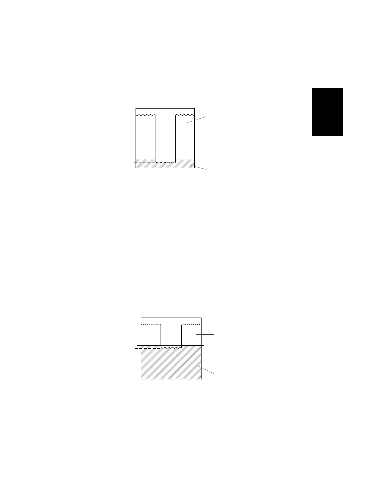
Low Density
1 May 1993 TONER DENSITY DETECTION AND TONER SUPPLY
6.4 ID SENSOR FUNCTION IN FIXED SUPPLY MODE
6.4.1 Black Development Unit
In fixed supply mode, toner is supp lied every cop y cycle accord ing to th e
fixed toner supply ratio data (S P mod e), the paper size da ta and the color
data. However, the tone r supp ly clutch is de-energized to prevent ove r-to nin g
when Vsp is lower than 1/8 Vsg.
Vsg 4V
Low Density
Detailed
Descriptions
Vsp
[BLACK]
1/8 Vsg
High Density
6.4.2 Color Development Unit
When a color development unit is installed, the CPU automatically selects the
fixed toner supply mode. The amount of toner supplie d de pe nd s on th e fixed
toner supply ratio (SP70 ), the paper size data and the kind of colo r d at a.
The CPU calculates the th reshold level for toner supply whe n the color
developer initial settin g (SP10) procedure is completed. This level is
determined by calculating the ave rag e of Vsp/ Vsg x 100(% ).
Since the fixed supply mode is selecte d whe n in color toner mode, it is
necessary to inhibit to ne r supp ly if the ton er de nsity becomes high to prevent
over-toning. The CPU checks Vsp once every 5 cop y cycles. If Vsp becomes
lower than the thresho ld level, the CPU stops supplying to ne r. Toner supply
resumes when Vsp rises above the thre sho ld leve l a gain.
Vsg 4V
Vsp
[COLOR]
Threshold Level
High Density
The threshold level (a pe rcen tage) for each color can be monit ore d in SP80
(Red), 81 (Green) and 82 (Blue).
2-39
Page 63

TONER DENSITY DETECTION AND TONER SUPPLY 1 May 1993
6.5 ABNORMAL CONDITION IN TONER DENSITY
DETECTION
If the Vsg goes below 2.5 volts (Vsg abnormal) or Vsp goes above 2.5 volts
(Vsp abnormal) 5 times in a row, the CPU determines that toner density
detection is abnormal. The CPU changes from the det ect supply mode to the
fixed supply mode. At the same time either the Auto ID indica to r o r t he
selected manual ID level start s blinkin g, and the machine can be operated.
Abnormal Condition In Toner Density Detection
SP55 display
Vsp Vsg
varies 0.00
varies 5.00
Vsg ≤ 2.5 (Vsg abnormal)
Vsp ≥ 2.5 (Vsp abnormal)
Conditions
6.6 DEVELOPMENT BIAS TONER DENSITY DETECTION
The development bias for t he ton er density detection consists of the fo llowin g
2 factors:
Development bias voltage = Toner density adjustment factor
+
Vd correction factor (Black toner only)
The development volta ge for th e Vr correction is 0 volt.
6.6.1 Toner Density Adjustment Factor
Toner
density
Normal 0 –280 volts –240 volts –320 volts –300 volts
Low 1 –240 volts –200 volts –280 volts –260 volts
High 2 –300 volts –260 volts –340 volts –320 volts
Higher 3 –320 volts –280 volts –360 volts –340 volts
Lower 4 –200 volts — — —
Highest 5 –340 volts — — —
Developer initial setting –340 volts –280 volts –320 volts –300 volts
SP data
(SP33 and SP75)
Development bias voltage
Black toner Red toner Green toner Blue toner
The development bias can be ad just ed by SP3 3 fo r black toner or SP75 for
color toner to adjust the toner densit y le vel. The above chart shows the
development bias volta ge corresponding to setting of SP33 or SP75. This
adjustment should be used only whe n the exposure lamp voltage adju stment
(SP48) and the base bia s adju stment (SP37 or SP79) for cop y ima ge can no t
achieve the desired image dens ity.
2-40
Page 64

1 May 1993 TONER DENSITY DETECTION AND TONER SUPPLY
6.6.2 Vd Correction Factor (Only for Black Toner)
The development bias for t oner de nsit y det ection is changed automatically to
compensate for varia tions of the triboelectric charge of the developer.
The CPU monitors Vsp and Vsg and ca lcula tes the average of Vsp/Vsg x
100(%) during the black developer initial setting (SP65). The result of the
calculation can be monitored by SP64.
The CPU has a software counter (no SP mode displa y) to cou nt the numb er
of copies made with the deve loper. The counter resets to "0" wh en SP65 is
performed.
Vd correction is made based on the results of the calculation and the dat a of
the software counter as shown in the following table:
Detailed
Descriptions
SP data (SP64) Vsp/Vsg x 100 (%)
0
1
2
3
4
12 to 15
0 to 7
8 to 11
16 to 21
More than 22
Change of development bias voltage
0 to 499 copies More than 500 copies
±0 volts
–40 volts
–20 volts
±0 volts
±0 volts
±0 volts
±0 volts
±0 volts
+20 volts
+40 volts
2-41
Page 65

TONER DENSITY DETECTION AND TONER SUPPLY 1 May 1993
6.7 TONER SUPPLY AND AGITATOR DRIVE MECHANISM
[H]
[F]
[J]
[I]
[F]
[G]
[E]
[C]
[A]
[D]
[B]
The toner supply clutch gear [A] turns when the main motor [B] is on and the
development clutch sole no id is de-energized. The transmission of this
rotation to the toner supply drive gear [C] is controlle d by the tone r supply
clutch [D].
When the toner supply clutch energ izes, the toner supply clutch engages and
starts turning the toner sup ply drive gear. The toner supply drive gear turn s
the toner supply roller gear [E] . Ton er catches in the grooves on the toner
supply roller [F]. Then, as the groo ves turn past the pin hole plate [G], the
toner drops into the de velopment unit through th e pin holes.
The toner agitator [H] mecha nism, which is contained in the toner cartridg e,
prevents toner from blocking. The toner agitat or ge ar [I] turns whenever the
toner supply clutch soleno id is e ng aged . Rotation passes through the toner
cartridge casing to the ag itator junction [J].
2-42
Page 66

1 May 1993 TONER DENSITY DETECTION AND TONER SUPPLY
6.8 TONER SUPPLY AMOUNT
This copier has two different ways of controlling the amount of toner supplied.
Normally, the detect supply mode controls toner supply f or the bla ck
development unit; however, a fixed supply mode also can be selected by
SP30. When the color development unit is installed, the fixed supply mode
controls toner supply regardless of the settin g of SP30.
6.8.1 Detect Supply Mode (SP30 = 0)
The amount of ton er supplied depends on the ID sensor data, the dete ct
toner supply ratio data, and th e paper size . The ton er sup ply clut ch on time in
each copy cycle is calculated as follows:
Toner Supply Clutch ON Time = I x T x P (pulses)
Where: I = ID Sensor Data
T = Detect Toner Supply Ratio Data
P = Paper Size Data
Detailed
Descriptions
For example: Vsp = 0.65 volts, which means the toner
supply level is "2" and the ID sensor = 29.
The data of SP31 is set to "0".
The toner supply ratio is 15 % and th e toner
supply data = 2.
Paper size is A4 or LT.
The paper size data = 1.
Toner Supply Clutch ON Time = I x T x P
= 29 x 2 x 1
= 58 (pulses)
= 232 (m sec.) (1 pulse = 4.0 m sec.)
2-43
Page 67

TONER DENSITY DETECTION AND TONER SUPPLY 1 May 1993
ID Sensor Data
Vsp/Vsg x100
(Vsp, if Vsg = 4.0 volts)
0 to 12.5%
(0 to 0.5 volts)
12.5 to 15.0%
(0.5 to 0.6 volts)
15.0 to 17.5%
(0.6 to 0.7 volts)
17.5 to 22.5%
(0.7 to 0.9 volts)
22.5 to 62.5 %
(0.9 to 2.5 volts)
(See note below.)
62.5 to more than 100 %
(2.5 to 5.0 volts)
Toner supply level
(Toner supply ratio, if SP31 = 0)
No toner supply
(0 %)
1
(3.75 %)
2
(7.5 %)
3
(15 %)
4
(30 %)
Fixed supply mode
ID sensor data
0
15
29
59
118
(Toner end level)
N/A
(Abnormal condition)
NOTE: If this condition is detected three times consecutively, the tone r
supply ratio rises to 60% (ID Sensor Data = 236), which is double
that at toner supply level 4.
Detect Toner Supply Ratio Data (SP31)
SP data (SP31) Toner supply ratio Toner supply ratio data
0 15% 2
17%1
2 30% 4
3 60% 8
Paper Size Data
Paper size Paper size data
Paper size ≤ A4 or LT
Paper size > A4 or LT 2
1
2-44
Page 68

1 May 1993 TONER DENSITY DETECTION AND TONER SUPPLY
6.8.2 Fixed Supply Mode (SP30 = 1)
The amount of toner sup plied depends on the fixed to ne r supp ly ratio data,
the paper size data and the color data. The toner supply clutch on time in
each copy cycle is calculated as follows:
Toner Supply Clutch ON Time = T x P x 2 x C (pulses)
Where: T = Fixed Toner Supply Ratio Data
P = Paper Size Data
C = Color Data
For example: The data of SP32 is set to "0".
The toner supply ratio is 7.0 % and the toner
supply data = 2.
Paper size is A4. The paper size data = 29.
Black toner is used. The color data = 1.
Toner Supply Clutch ON Time = T x P x 2 x C
= 2 x 29 x 2 x 1
= 116 (pulses)
= 464 (m sec.) (1 pulse = 4.0 m sec.)
Detailed
Descriptions
2-45
Page 69

TONER DENSITY DETECTION AND TONER SUPPLY 1 May 1993
Fixed Toner Supply Ratio Data (Black Toner: SP32)
SP data (SP32) Toner supply ratio Toner supply ratio data
0 7.0% 2
1 3.5% 1
2 10.5% 3
3 14.0% 4
Fixed Toner Supply Ratio Data (Color Toner: SP70)
SP data (SP70) Toner supply ratio Toner supply ratio data
0 14.0% 2
1 7 .0% 1
2 21.0% 3
3 28.0% 4
Paper Size Data
Paper size Paper size data
A3 58
B4 43
A4 29
B5 23
A5 15
B6 11
11" x 17" 55
8
1/2" x 14" 37
8
1/2" x 11" 27
5
1/2" x 81/2"14
Universal (
Paper size not detected 0
)
*
29
Color Data
Blue or Green 1.2
Color Color data
Black 1
Red 2
2-46
Page 70

1 May 1993 TONER DENSITY DETECTION AND TONER SUPPLY
6.9 BLACK TONER END DETECTION
The image density senso r is used to detect a toner end condit ion in bot h
detect and fixed supply modes for th e black toner.
6.9.1 Near Toner End Condition
When (Vsp/Vsg x 100) become s greater than 22.5, the toner density
detection cycle changes from eve ry 10 cop ies to 5 copie s.
When this condition is detected three times consecu tively, the toner supply
ratio becomes two times the amo un t of ton er sup ply leve l 4 . The result ing
toner supply ratio is 60% , and the ID sensor data is 236.
Then, when this condition is detected five times consecutively, the CPU
determines that it is the near end condition and start s blinkin g the Add Toner
indicators.
6.9.2 Toner End Condition
After the Add Toner ind icat or sta rts blinking (Near Toner End Condition), the
operator can make 50 copies. If the toner cartridge is not replaced within 50
copies, copying is inhibit ed and a ton er end condition is determined. In th is
condition, the Add Toner indicator lights.
Example:
Copy number
1st ~ 5th copies 1st copy 22.6 30%
6th ~ 10th copies 6th copy 22.6 30%
11th ~ 15th copies 11th copy 22.6 60%
16th ~ 20th copies 16th copy 22.6 60%
21st copy 21st copy 22.6 60%
l
l
l
71st copy — — —
Toner density
detection cycle
l
l
l
Vsp/Vsg
x 100
l
l
l
Toner supply ratio
(If SP31 = 0)
l
l
l
Indicator
Add Toner indicator
starts blinking (near
toner end condition)
Add Toner indicator
blinks (near toner
end condition)
Add Toner indicator
lights (toner end
condition)
Detailed
Descriptions
2-47
Page 71

TONER DENSITY DETECTION AND TONER SUPPLY 1 May 1993
When (Vsp/Vsg x 100) becomes grea ter than 37.5 two times consecutively,
the CPU determines immediat ely that the re is a ton er end con dition and
copying is inhibited. This causes the Add Toner indicator to light.
Example:
Copy number
1st~5th copies 1st copy 30.5 30%
6th~10th copies 6th copy 37.7 30%
16th copy 16th copy 37.7 —
Toner density
detection cycle
Vsp/Vsg
x 100
Toner supply ratio
(If SP31 = 0)
Indicator
Add Toner indicator
lights (toner end
condition)
6.9.3 Toner End Recovery
After the toner cartridge is replaced and the front cover is closed, the CPU
turns on the main moto r, de -en e rg izes the development clutch solenoid, and
turns on the toner supply clutch for 35 seconds to supply toner to the empty
toner supply unit from the ton er cart ridg e.
The CPU checks Vsg and Vsp four times at the end of this p erio d to cle ar th e
toner end condition .
When the average of (Vsp/Vsg x 100) becomes less than 22.5 or th e ave rage
of (Vsp/Vsg x 100) becomes less than 80% of the last detect ion bef ore
replacing the toner cartridge, the toner end or near end condition is cleared.
If the toner end or nea r end cond ition is not cleared, copying is inhibited.
This prevents the customer fro m clearin g the near end or toner end condition
by simply opening and closing the front cover or tu rning off and on the main
switch.
2-48
Page 72

[G]
[B]
1 May 1993 TONER DENSITY DETECTION AND TONER SUPPLY
6.10 COLOR TONER END DETECTION
[E]
[D]
[C]
[F]
Detailed
Descriptions
[A]
The toner agitator gear [A] ha s a cam [B] (t he ton er end cam) on it s inne r
surface, and it rotates only whe n to ner is sup plie d. The cam fo llowe r on th e
end of the toner end lever [C] rides on the surface of the ton er en d cam
(spring pressure). The opposite end of the toner end lever alt ern at ely pre sses
and releases the tone r end arm [ D] as th e cam turns. The toner end plate [E ],
which is in the toner hopper, is mount ed on th e same shaft as the toner end
arm.
When there is sufficient toner in the hopper, the tone r e nd plat e is prevented
from moving by the toner. Therefore, even when the toner end lever drops to
the lowest position on th e cam (releasing the toner end arm), th e toner end
arm does not move and the to ne r end sensor [F] is not activated.
When there is insufficient toner in the hopper, the ton er en d plate can move.
When the toner end lever re lea ses the toner end arm, the tone r end plat e
lowers and the actuato r [ G] on th e toner end arm moves into the tone r end
sensor. The CPU receives a single pulse from th e toner end sensor.
2-49
Page 73

TONER DENSITY DETECTION AND TONER SUPPLY 1 May 1993
If this condition is detected by the CPU two times consecutively, the Add
Toner indicator starts blinking.
After the indicat or sta rts blinking, 50 copies can be made. If a new to ne r
cartridge is not added within that 50 copy interval, the Add Toner indica to r
stops blinking (stays on) and copying is inhibited. If the main switch is turne d
off and on after this, only 1 copy can be made each time.
The toner end condition is normally detected by the mechanism described
here. However, it can also be detected using the ID sensor. The Ad d Toner
indicator will start blinking if Vsp/ Vsg exceeds 1.1 x threshold level 10 time s
in a row. The threshold leve l is th e ave rage of Vsp x Vsg, which is calculated
and stored in RAM when the color developer initial settin g (SP10) procedure
is completed.
When the toner cartridge is replaced and the front cover is closed, the CPU
turns on the main moto r, de -en e rg izes the development clutch solenoid, and
turns on the toner supply clutch for approximately 3 seconds to supply to ne r
to the empty toner supply unit from th e tone r cartrid ge . A to ner e nd det ect ion
is also done during this 3 second period. The CPU pe rfo rms this op era tion a
maximum of 3 times (9 seconds) to clear the ton er end condition.
6.11 COLOR TONER SUPPLY UNIT INI TI AL SETTING (SP63)
When the new color developmen t un it is insta lled or the color toner supply
unit is replaced with a new one, the toner sup ply un it init ial setting (SP63)
must be performed to preve nt the CPU from falsely detectin g to ne r e nd.
When SP63 is performed, the CP U turn s on th e main motor, de-energizes
the development clut ch solenoid, and turns on the to ne r supp ly clu tch fo r
approximately 3 seconds to supply t oner to the empt y ton er sup ply un it fro m
the toner cartridge. A ton er en d de tection is also done during this 3 second
period. The CPU performs this operation a maximum of 3 time s (9 secon ds)
to clear the toner end con dit ion.
2-50
Page 74

1 May 1993 IMAGE TRANSFER AND PAPER SEPARATION
7. IMAGE TRANSFER AND PAPER
SEPARATION
[B]
Detailed
Descriptions
[F]
[E] [D] [C]
[A]
7.1 PRE-TRANSFER LAMP (PTL)
After the latent imag e is d eve loped but before the image is tra nsf erred to the
copy paper, the drum surface is illuminated by the pre -tra nsf er lamp [A]. This
illumination reduces the negative pote nt ial on the drum surf ace [B] . This
prevents the toner particles f rom being re-attracted to the negat ively cha rged
drum during the paper separatio n process. It also makes image transfer an d
paper separation easier.
7.2 IMAGE TRANSFER
A high negative voltage (–4.8 kilovolts) is applie d to the tran sfe r coron a wire
[C], and the corona wire generates ne ga tive ions. These negative ions are
applied to the copy paper, and the negative charge attracts the positively
charged toner away from the dru m and onto th e paper. In addition, the paper
is held against the drum by t he positive counter charge on the drum.
2-51
Page 75

IMAGE TRANSFER AND PAPER SEPARATION 1 May 1993
7.3 PAPER SEPARATION
After image transfer the cop y must be sepa rat ed from the dru m. To break the
attraction between th e paper and the drum, the sepa rat ion corona wire [D]
applies an ac corona to the reverse side of the paper. The stiffness and
weight of the paper causes it to sepa rat e fro m the drum.
The negative charge on the paper (fro m the tran sfe r co ron a) is not
completely discharge d until th e pa per is fa r eno ugh fro m t he drum th at the
toner will not be reattracted to the drum. The two pick-off pawls [E] ensure
that thin, low stiffness pap er an d upward curled paper separate complete ly.
The spurs [F] prevents the unfused toner on the pap er fro m b ein g smeared
by the pick-off pawls.
2-52
Page 76

1 May 1993 IMAGE TRANSFER AND PAPER SEPARATION
7.4 PRE-TRANSFER LAMP AND TRANSFER/SEPARATION
CORONA CIRCUIT
CN121-2
CN121-1
[24] VA
TC2 Trig [▼24]
TC1 Trig [▼24]
SC Trig [▼24]
[▼24] PTL
VA [24]
GND [0]
CN112-14
CN112-11
CN112-12
CN112-13
CN112-10
CN1-1
CN1-4
CN1-3
CN1-2
CN1-5
TC/SC
Power Pack
(P2)
Transfer Corona
Separation Corona
Main Board
PTL (L5)
(PCB1)
When the Start key is pressed, the main bo ard out pu ts Low sig nals to tu rn on
the pre-transfer lamp (PTL) and the TC/ SC power pack for th e tra nsf er and
separation coronas.
The pre-transfer lamp is comp ose d of 50 LEDs su pplied by +24 volts.
Detailed
Descriptions
The TC/SC power pack has a dc to dc con vert er an d a dc to ac inverter. The
dc to dc converter changes +24 volts to –4.8 kilovolts for the transfer coron a.
The inverter changes +2 4 volt s to th e 5.0 kilovolts ac (500 Hz) for the
separation corona.
The TC2 trigger is only used for the seco nd sid e cop ies in du ple x copy mode.
This shifts the corona current to incre ase transfer efficiency.
The separation corona circuit in the TC/SC power pack has a current leak
detection circuit for safety. When this circuit detect s tha t more tha n 2
milliampere is supplied to the separation corona, th e sep aration corona turns
off immediately. When th e main switch is turned off and on, or the front cove r
or the exit cover is opened and closed, th is cond itio n is cleared.
2-53
Page 77
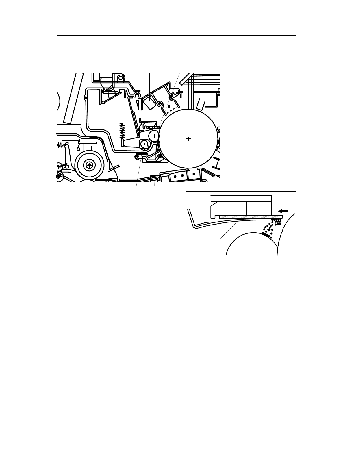
DRUM CLEANING 1 May 1993
8. DRUM CLEANING
8.1 OVERVIEW
[E]
[B]
[C]
[D]
The cleaning brush [A ] an d clea ning blade [B] remove any to ner re main ing
on the drum [C] afte r t he ima ge is transferred to the paper.
The cleaning brush and drum move in opposite direction s at th eir po int of
contact. The clean ing brush removes paper dust and nearly half of the ton er
from the drum surface to redu ce the cleaning load placed on th e blade.
The cleaning blade re move s the re main ing toner. The falling toner catches in
the fibers of the cleaning brush and is carried inside the clean ing unit. The
toner collection roller [D] carrie s the used toner to the used ton er ta nk. The
light of the quenching lamp [E] neutralizes any charge remaining on the drum
in preparation for the next copy cycle.
[A]
[F]
The cleaning blade re lea ses when the release knob is pressed . This clea ns
the edge of the cleaning blad e using the blade scraper [F], which is mo unted
under the cleanin g bla de .
2-54
Page 78

1 May 1993 DRUM CLEANING
8.2 DRIVE MECHANISM
[G]
[H]
[D]
[C]
[F]
[E]
[A]
[B]
Detailed
Descriptions
The rotation of the main motor is tra nsmit te d to the clean ing unit thro ug h the
main motor gear [A], the relay ge ar [B ], and the cleaning drive gear [C].
The gear [D] driven by the cleaning drive gear pa sses th e rot at ion to the
toner collection roller g ea r [ E] and to the cleaning brush gear [F] through the
idle gears [G].
The cleaning blade [H] is mo un te d in the center of the blade and is tilt ed to
apply even pressure.
2-55
Page 79
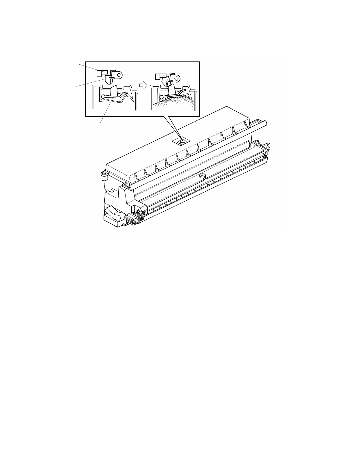
DRUM CLEANING 1 May 1993
8.3 TONER OVERFLOW DETECTION
[C]
[B]
[A]
The toner overflow detection mechanism stops copier operation when the
used toner tank gets full. When the ta nk gets fu ll, th e pre ssure of th e use d
toner pushes up a mova ble plate [A] mounted in the top of the used toner
tank. As this plate move s up, it ra ises th e toner overflow actuator [B]. When
the actuator moves into the toner overflow sensor [C], the CPU starts to blink
"E70" on the operation pa ne l. Af ter the "E70" starts to blink, 25 0 cop ies can
be made. Then, after 250 copies the "E70" stops blinking (stays on) and
copying is inhibited.
2-56
Page 80

1 May 1993 QUENCHING
9. QUENCHING
[A]
[B]
Detailed
Descriptions
In preparation for the ne xt cop y cycle , ligh t fro m the quench ing lamp (QL) [A]
neutralizes any charge remainin g on the drum [B ].
The neon lamp is used for quen chin g an d it is t urn ed on whe ne ver th e main
motor rotates.
2-57
Page 81

PAPER FEED AND REGISTRATION 1 May 1993
10.PAPER FEED AND REGISTRATION
10.1 OVERVIEW
[A]
[D]
[E]
[H]
[C]
[J]
[I]
A110 copier has two paper feed statio ns (1 cassette + 1 paper tray) and
manual feed table [A ]. A11 1 cop ier ha s three paper feed stations (1 casse tt e
+ 2 paper trays) and manual feed table.
The first feed station uses a cassette [B] which can load 500 sh eets, and the
second and third feed station s use a paper t ray [C] which can load 250
sheets. The manual feed table can load 50 sheets. The manual fee d table
utilizes the feed mechanism of the first fee d sta tio n.
The first feed station uses a FRR feed system. Rotation of the pick-up roller
[D] drives the top sheet of pape r fro m t he ca sset te to the feed and the
reverse rollers. The feed [E] and reverse [F] rollers t hen take ove r the paper
drive. If more than one sheet is fed by the pick-up roller, the reverse rolle r
rotates in the opposit e direction and prevents all but the top sheet from
passing through to the reg istration rollers [G].
[B]
[F]
[G]
The second and third feed statio ns use the semicircular feed roller [H] and
corner separator [I] system. The semicircular feed roller makes one rotat ion
to drive the top sheet of paper to the relay rolle rs [ J], which th en feed th e
sheet to the registration rollers. The corner separato r allows on ly one shee t to
feed.
2-58
Page 82

1 May 1993 PAPER FEED AND REGISTRATION
10.2 FRR FEED SYSTEM
[B]
[A]
[C]
Detailed
Descriptions
This copier uses an FRR (Feed + Reverse Roller) paper feed system which
utilizes three rollers.
10.2.1 Pick-up Roller
The pick-up roller [A] is not in contact with the paper sta ck bef ore it starts
feeding paper. Short ly a ft er the Start key is pressed, the pick-up roller drops
down and feeds the top sheet betwee n th e feed [B] and the re verse rollers
[C]. At almost the same time th at the paper’s leading edge arrives at the fee d
roller, the pick-up roller lifts off the paper stack so that it does not interfere
with the operation of the feed and reverse rollers. The feed an d reve rse
rollers then take over the paper feed process.
10.2.2 Feed and Reverse Rollers
There is a one-way bearing inside the fee d rolle r so it can tu rn on ly in one
direction. The reverse roller is driven in the opposit e dire ctio n to the feed
roller. The reverse roller, howeve r, is driven through a slip clutch (torque
limiter clutch) which allows it to turn in either direction depending on the
friction between the rollers. A spring keeps the reverse roller in contact with
the feed roller.
2-59
Page 83

F3
PAPER FEED AND REGISTRATION 1 May 1993
[B]
F1
F2
F2
[B]
F1 F1
[A]
F2
F3
F1
[A]
The direction that the reverse roller [A] tu rns depend s on the frictional forces
acting on it. The slip clutch applies a constant clockwise force (F1). When
there is a single sheet of paper being driven between the rollers, the force of
friction between the feed roller [B] and the paper (F2) is greate r then F1. So,
the reverse roller turns counterclockwise.
If two or more sheets are fed betwe en the rollers, the forwa rd fo rce on the
second sheet (F3), be come s le ss tha n F1 because the coefficient of friction
between the two sheets is small. So , the reverse roller starts turning
clockwise and drives the second sheet back to the cassette.
2-60
Page 84

[G]
[D]
1 May 1993 PAPER FEED AND REGISTRATION
10.3 1ST FEED STATION PAPER LI FT ME CHANI SM AND
PAPER END DETECTION
[H]
[K]
[J]
[I]
[A]
Detailed
Descriptions
[F]
[E]
[C][B]
10.3.1 Paper Lift Mechanism
When the cassette [A] is inse rte d into the copier, the cassette actuator pin [B]
is pushed down by the cassett e. The paper lift clutch unit [C] moves do wn
and then the paper lift gear [D] engag es with the secto r gea r [ E] .
Simultaneously, the paper size actuator [F] act ua tes the paper size switch [G].
Under the following conditio ns, the CPU checks the paper lift sensor [H] to
see if the paper is at the feed position:
1. When the Start key is pressed.
2. When the warm-up condition chang es to the read y cond itio n.
3. When the manual feed table is closed.
2-61
Page 85

PAPER FEED AND REGISTRATION 1 May 1993
If the paper has not been raised to the feed position, th e CPU turns on the
main motor and the paper lift clut ch. The paper lift gear turns the sector ge ar
and the bottom plate raises until the top sheet pushe s up th e pa pe r lift sensor
feeler [I]. When the paper lift senso r is de-act ua te d, the pap er lift senso r
sends a Low signal to the main bo ard , an d then the main motor and the
paper lift clutch are turned off.
If the tray lift sensor stays HIGH fo r 7 secon ds af te r the paper lift clu tch is
turned on, "U5" lights i n the operation panel.
As paper is fed into the copier, th e leve l of pa per st ack gets lower. If the level
becomes too low, the paper lift senso r is actua te d and the CPU en erg izes th e
paper lift clutch until the top sheet raises the feeler to de-actuate the paper lift
sensor again. This ensures th at the pap er is always at the correct feed height.
10.3.2 Paper End Detection
When the cassette runs ou t of paper, the paper end feele r [ J] dro ps through a
slot in the cassette bottom plate. As it drops, the paper en d sensor [K] is
actuated by the feeler. The paper end sensor then sends a HIGH signal to
the main board. The Add Pap er indicator then turns on. Th e Wait indicator
keeps turning on and th e mach ine stops after the copy cycle is finished.
2-62
Page 86

1 May 1993 PAPER FEED AND REGISTRATION
10.4 2ND/3RD FEED STATION PAP ER LI FT ME CHANISM
AND PAPER END DETECTION
[I]
[H]
[J]
[G]
[K]
[E]
[A]
[F]
[B]
[C]
[D]
10.4.1 Paper Lift Mechanism
When the paper tray [A] is closed after paper is loaded, the plate release
slider [B], which is mounted on the bot to m part of th e paper t ray, is pushe d by
the projection [C] of th e copier frame and the release slid er come s off the
bottom plate hook [D].
Detailed
Descriptions
Once the release slider comes of f, the botto m p lat e is raised by the pressure
springs [E] and the top sh eet pu shes up the corner separato rs [F]. This keeps
the stack of paper at the correct height.
10.4.2 Paper End Detection
When the paper tray runs out paper, th e pape r end fee ler [G ] drops through a
slot in the tray bottom plat e. The paper end actuator [H] , which is on the
same shaft as the paper en d fe eler, pivots into the paper end senso r [ I] . The
paper end sensor sends a HIG H signa l t o th e main boa rd an d th en the Add
Paper indicator turns on . The Wait indicator keeps turnin g on and the
machine stops after t he copy cycle is f inish ed .
When the paper tray is pulled out, the release arm [J], which is spring loaded,
rotates clockwise and raises the paper end actuator and the paper end
feeler. This prevent s the pap er en d fe eler from being damaged by the pa pe r
tray. When the paper tray is closed, the proje ctio n [K] on the paper tray
pushes the release arm to rele ase the pap er en d act ua tor and the paper end
feeler.
2-63
Page 87

PAPER FEED AND REGISTRATION 1 May 1993
10.5 PAPER SIZE DETECTION
10.5.1 1st Feed Station
[A]
SW3–
1 2 3 4 5
[B]
The paper size switch (SW3) [A] in the cassette entrance detects the pa per
size. The paper size switch has five microswitches (SW3 -1 through 3-5)
inside. The paper size switch is act ua te d by an actu ator plate [B] on the rear
of the cassette. Each paper size has its own unique combina tion of notches
in the plate. The CPU receives a LO W signa l from th e microswitches
activated by the act uator and determines which cassette was inserted.
2-64
Page 88

1 May 1993 PAPER FEED AND REGISTRATION
Paper Size Detection Tab le (1st Feed Sta tio n)
Paper Size
Universal 0 0 0 0 0 ❋
A3
B4
A4 (sideways)
A4 (lengthwise)
B5 (sideways)
B5 (lengthwise)
A5 (sideways)
A5 (lengthwise)
B6 (sideways)
B6 (lengthwise)
F (8" x 13")
Return Post Card
Post Card
11" x 17"
11" x 81/2"
11" x 15"
10" x 14"
81/2" x 14"
81/2" x 13"
81/2" x 11"
81/2" x 51/2"
81/4" x 13" (14")
8" x 101/2"
8" x 10"
51/2" x 81/2"
Switch 3 –
1 2 3 4 5
1 0 0 0 0
1 1 0 0 0
0 0 1 0 0
1 0 1 0 0
0 1 1 0 0
1 1 1 0 0
0 0 0 1 0
1 0 0 1 0
0 1 0 1 0
1 1 0 1 0
1 0 0 1 1
0 0 1 1 0
1 0 1 1 0
0 0 0 0 1
1 0 0 0 1
0 1 0 0 1
1 1 0 0 1
0 0 1 0 1
1 0 1 0 1
0 1 1 0 1
1 1 1 0 1
0 0 0 1 1
0 1 0 1 1
1 1 0 1 1
0 0 1 1 1
Size Indication
A3
B4
A4
A4
❋
❋
A5
A5
❋
❋
F
❋
❋
11 x 17
81/2 x 11
❋
❋
81/2 x 14
❋
81/2 x 11
51/2 x 81/2
❋
❋
❋
51/2 x 81/2
Detailed
Descriptions
No Cassette 1 1 1 1 1 —
0: Actuated (Low)
1: Not Actuated (High)
2-65
Page 89

[A] SW4/SW9
[B]
SW5/SW10
1
PAPER FEED AND REGISTRATION 1 May 1993
10.5.2 2nd/3rd Feed Station
[C]
2
1
2
Two paper size switches (SW4 [A] and SW5 [B] fo r 2nd feed sta tion, SW9 [A]
and SW10 [B] for 3rd feed station) on the rear frame dete ct th e paper size.
Each paper size switch has two microswitches.
The paper size switches are actuate d by a paper size det ect ion block [C] on
the rear of the paper tray. Each pape r size has its own uniq ue combin at ion of
holes in the block.
The CPU receives a LOW signal from the microswitches activated by the
block and determines which paper size is used in the paper tray.
2-66
Page 90

1 May 1993 PAPER FEED AND REGISTRATION
Paper Size Detectio n Tab le (2nd and 3rd Feed Station)
Paper Size
SW4/SW9 SW5/SW10
Size Indication
1 2 1 2
❋ (See Note) 0 0 0 1 ❋
A3
B4
A4 (sideways)
A4 (lengthwise)
B5 (sideways)
A5 (sideways)
F (8" x 13")
11" x 17"
11" x 81/2"
81/2" x 14"
81/2" x 11"
1 1
0 1
0 1
1 1
0 0
1 0
1 0
1 1
0 1
0 1
1 1
1 0
0 0
1 1
0 1
1 0
1 1
0 0
1 0
1 1
0 0
0 1
A3
B4
A4
A4
❋
A5
F
11" x 17"
81/2" x 11"
81/2" x 14"
81/2" x 11"
0 0 0 0 Duplex Unit
0: Actuated (Low)
1: Not Actuated (High)
NOTE: 1. SP96 (special paper size setting) sets the appropria te paper size
for special paper when setting the " ❋" mark on the paper size
detection block.
2. Duplex modes cannot be selected.
Detailed
Descriptions
2-67
Page 91

[B]
PAPER FEED AND REGISTRATION 1 May 1993
10.6 PAPER FEED DRIVE MECHANISM
10.6.1 1st Feed Station
[H]
[F]
[A]
[E]
[G]
[C]
[D]
Through several gears and a timing belt, main motor rotation is transmitted to
the relay gear [A] and th en the 1st pa pe r fee d clut ch ge ar [B]. The 1st paper
feed clutch gear turns the reve rse rolle r d rive gear [C]. The paper feed timing
is controlled by the 1st paper feed clut ch sole no id [D] .
The pick-up roller [E] is normally in contact with the paper sta ck. Whe n the
leading edge of the pap er pa sses between the feed roller [F] and th e reve rse
roller [G], the pick-up roller is then lifted up by the pick-up roller re lea se
solenoid [H]. After th e tra iling edge of the pape r passes un der t he pick-up
roller, the pick-up roller release solenoid is de-energized and the pick-up
roller drops back onto the paper stack in preparation for the next copy cycle .
2-68
Page 92

[G]
[B]
1 May 1993 PAPER FEED AND REGISTRATION
10.6.2 2nd Feed Station
[E]
[C]
[F]
[A]
[D]
Detailed
Descriptions
Main motor rotation is transmit ted to the relay roller clutch gear [A] through
gears and a timing belt. The paper feed timing is controlled by the relay roller
clutch [B] and the 2nd feed clutch [C] . The upp er rela y roller ge ar [D]
transmits rotation to the 2nd feed clutch gear [E] through the relay gear [F]
only when the relay roller clutch is on.
Both the relay roller clutch an d the 2nd paper feed clutch turn on at th e same
time to start paper feed. The 2nd feed clut ch is ene rgize d fo r 500
milliseconds to transfer drive to the 2nd feed roller sh aft an d turns the 2nd
feed rollers [G]. The 2nd feed rollers stop turning when the 2nd feed clutch
gear completes one rotation. The relay roller clut ch stays energized until the
leading edge of the paper reaches the registration rollers.
2-69
Page 93

[B]
PAPER FEED AND REGISTRATION 1 May 1993
10.6.3 3rd Feed Station (A111 Copier Only)
[H]
[A]
[E]
[F]
[I]
[C]
[J]
[D]
[G]
Main motor rotation is transmit ted to the relay roller clutch gear [A] through
gears and a timing belt. The paper feed timing is controlled by the relay roller
clutch [B] and the 3rd paper feed clutch [C]. Whe n the relay roller clutch is
energized, the relay roller clutch gear tran smits rot at ion to the lower relay
roller gear [D] through a timing belt [E] and the timing pulleys. Then, th e lower
relay roller gear transmits rotation to the 3rd feed clutch ge ar [F] thro ugh the
relay gear [G].
Both the relay roller clutch and the 3rd pape r feed clutch turns on at the same
time to start paper feed. The 3rd fe ed clutch is energized for 500 milliseconds
to transfer drive to the 3rd feed roller shaft and turns th e 3rd feed rolle rs [H].
The 3rd feed rollers stop turning when the 3rd feed clutch gear completes
one rotation. The relay roller clut ch sta ys ene rgize d un til the lea ding edge of
the paper reaches the registration rollers.
The relay sensor [I] is locate d just aft er th e lower relay roller [J]. This sensor
is used for paper misfeed detection .
2-70
Page 94

1 May 1993 PAPER FEED AND REGISTRATION
10.7 SLIP CLUTCH MECHANISM
[D]
Detailed
Descriptions
[B]
[A]
[C]
[E]
[D]: Reverse Roller
[E]: Slip Clutch Cover
The slip clutch consists of two hubs conne cte d by a drive spring [A]. The
spring grips the input hub [B] loose ly and grips th e outp ut hub [C] tig ht ly. It
will slip if the resistance to rotation is too great. The hubs and spring are
precisely machined, and th e ou tput hub and spring slip when a single shee t
of paper feeds between the feed roller and reverse roller.
2-71
Page 95

[C]
PAPER FEED AND REGISTRATION 1 May 1993
10.8 MANUAL FEED TABLE
[A]
[B]
[D]
The manual feed table [A] uses the same feed mechanism as the first fe ed
station and a maximum of 50 sheets of sta ndard weight paper can be loaded.
When the manual feed table is opene d, a relea se leve r [ B] activa te s the
manual feed table switch (SW7) [C] and re lea ses th e pa pe r lift-u p clut ch un it
mechanically to drop do wn th e cassette bottom plate. At the same time the
pick-up roller release solenoid turns on to release the pick-up roller and the
paper end feeler [D] dro ps do wn into a slot in the manual feed tab le.
The manual feed table switch sen ds a LOW sig nal to th e main board so th at
the Manual Feed indicator turns on and the pick-up roller is lifte d up.
When paper is loaded onto the manual feed table, the manual feed is
selected automatically.
2-72
Page 96

[B]
1 May 1993 PAPER FEED AND REGISTRATION
10.9 PAPER REGISTRATION
[A]
[E]
[C]
[F]
[D]
[G]
[F]
Main motor rotation is transmit ted to the timing belt [A] throug h a series of
gears. The timing belt rotate the relay ge ar [B ] an d then the registration roller
clutch gear [C]. When the registration clutch [D] is energized, the rotation of
the clutch gear is transmitted to the lower registra tio n rolle r [E] .
Detailed
Descriptions
The registration rollers can be rotated by a knob in the front to ease misfe d
paper removal.
The registration sensor [F], which is positione d just before the re gist rat ion
rollers [G], controls the paper feed stop timing. The 1st paper fe ed clutch
stays on for 120 milliseconds and the relay roller clutch (2nd and 3rd paper
feed stations) stays on 114 millisecond s aft er th e lea din g edge of paper
actuates the registratio n sen sor. At th e end of the perio d, the CPU t urn s off
the 1st paper feed clutch or the relay roller clutch. This delay allows time for
the paper to press against the registration rolle rs and buckle slight ly to
correct skew.
The CPU energizes the registration clutch 1.4 second s (1st feed station) after
the Start key is pressed. The registration rollers then feed the paper to the
image transfer section.
2-73
Page 97

PAPER FEED AND REGISTRATION 1 May 1993
10.10 PAPER FEED AND MISFEED DETECTION TIMING
Timing Pulse
(4 msec/pulse)
Start Key
Main Motor
<1st Feed Station>
1st Feed Clutch
Solenoid
Pick-up Roller
Release Solenoid
Registration
Sensor
Registration
Clutch
<2nd Feed Station>
Relay Roller
Clutch
2nd Feed
Clutch
Registration
Sensor
Registration
Clutch
Exit Sensor
400ms
100
100
1500 2000 2500 3000 3500 40000 100
(A110 copier) 2500→1750 3250→1750
(A111 copier) 2445→1750 3140→1750
1750
1877 18772273 (A4S) 2273 (A4S) 1877 2273 (A4S)
J1 J1 J1
120ms
2000 2000 2000
1433 (A110 copier) 2183→1433 2933→1433 3683→1433
1557 (A111 copier) 2252→1557 2947→1557 3642→1557
2010 2010 2010
500ms 500ms 500ms 500ms
1750
2285 (LTS)
2010
120ms
2010
J1 J1 J1
114ms 114ms
2010
1750
2285 (LTS)
120ms
2010
2285 (LTS)
2010
2010
114ms
200020002000
J2 J3 J2
2700 2700
2.75 sec (A4 sidewise)
2.80 sec (LT sidewise)
A111 copier only
<3rd Feed Station>
Relay Roller
Clutch
3rd Feed
Clutch
Relay Sensor
Registration
Sensor
Registration
Clutch
1320 2010
100
500ms 500ms 500ms 500ms
2015→1320 2710→1320 3405→1320
2010
2010
JR JR JR JR
1587 1587 1587
2010 2010 2010
J1 J1 J1
114ms 114ms 114ms
2000 2000 2000
2-74
1587
Page 98

1 May 1993 PAPER FEED AND REGISTRATION
The registration sensor, the exit sen sor an d the rela y sensor (A111 copier
only) monitor the moveme nt of th e pa pe r t hro ug h th e pa pe r p at h. If th e CPU
determines that a misfeed exists, the Check Paper Path and the Misfeed
Location indicators turn on . Whe n th e main switch is turn ed on, or the front
cover or exit cover is closed, the CPU checks the se sen sors fo r initial
misfeed. During the copy cycle, the CPU performs the following misfeed
detection:
J1: Checks whether the registration sensor is actuated within 10
pulses (40 milliseconds) after the registration clutch turns on.
J2: Checks whether the exit sensor is actuated within 700 pulses
(2.8 seconds) after th e reg istration clutch turns on.
J3: Checks whether the copy paper has passed through the exit
sensor 2.75 (A4 sideways) or 2.80 (Let ter sideways) seconds
after the exit sensor has bee n act ua ted.
(A111 copier only)
Detailed
Descriptions
JR: Checks whether the relay sensor is actuated within 267 pulses
(1.07 seconds) afte r the 3rd fe ed clu tch turns on.
2-75
Page 99

[D]
IMAGE FUSING 1 May 1993
11.IMAGE FUSING
11.1 OVERVIEW
[F] [E]
[H]
[G]
[B]
After the image is tran sferred, the copy paper ente rs t he fusin g un it. The
image is fused to the copy p aper by the process of heat and pressure
through the use of a hot roller [A] and pressure roller [B] .
[A]
[C]
The fusing lamp [C] located inside the hot roller is turned on and off to
maintain the operat ing temperature of 185°C. The CPU monitors the hot
roller surface temperature through a thermistor [D] which is in contact with
the hot roller’s surface. A th ermofuse [E] protects th e fusing unit from
overheating.
The hot roller strippers [F] separate the cop y paper fro m t he hot roller an d
direct it to the exit rollers [G]. The exit sensor [H] monitors the progress of the
copy paper through th e fusing unit and acts as a misfeed detect or while the
exit rollers drive the copy paper to the copy tray. When the sort er is insta lled,
the paper sensor on the sorter also fu nct ion s as a misf eed dete ctor.
2-76
Page 100

[B]
1 May 1993 IMAGE FUSING
11.2 FUSING DRIVE RELEASE MECHANI SM AND COVER
SAFETY SWITCH
[A]
Detailed
Descriptions
[E]
[D]
[C]
The front cover is opened.
[E]
[D] [D]
The exit cover is opened.
[C]
The front cover and exit
cover are opened.
[E]
[C]
The fusing unit drive release mechanism automatically disengages th e fu sing
unit drive gear [A] when the front cover [B ] or th e exit cover is ope ne d. Th is
allows the fusing unit drive ge ar to ro ta te freely so that misfed paper can be
easily removed.
When the front cover and /o r the exit cove r is open ed , th e actuator plate [C]
pulls release wire [D] and the fu sing unit drive gear is d isen ga ged.
The actuator plat e also re lea ses the cover safety switch [E] removin g all
power from the copier and the optional peripherals.
2-77
 Loading...