

Page 1

DUPLEX
Page 2

1 May 1993 SPECIFICATIONS
1. SPECIFICATIONS
Copy Paper Size: A4/81/2" x 11" (sideways)
Paper Weight: 58 to 104 g/m2 (16 to 28 lb)
Paper Stack: 50 sheets
Dimension
(W x D x H):
516 x 529 x 90 mm
(20.4" x 20.9" x 3.6")
Weight: Approximately 5 kg (11 lb)
• Specifications are subje ct to change witho ut notice.
Duplex
1
Page 3
COMPONENT LAYOUT 1 May 1993
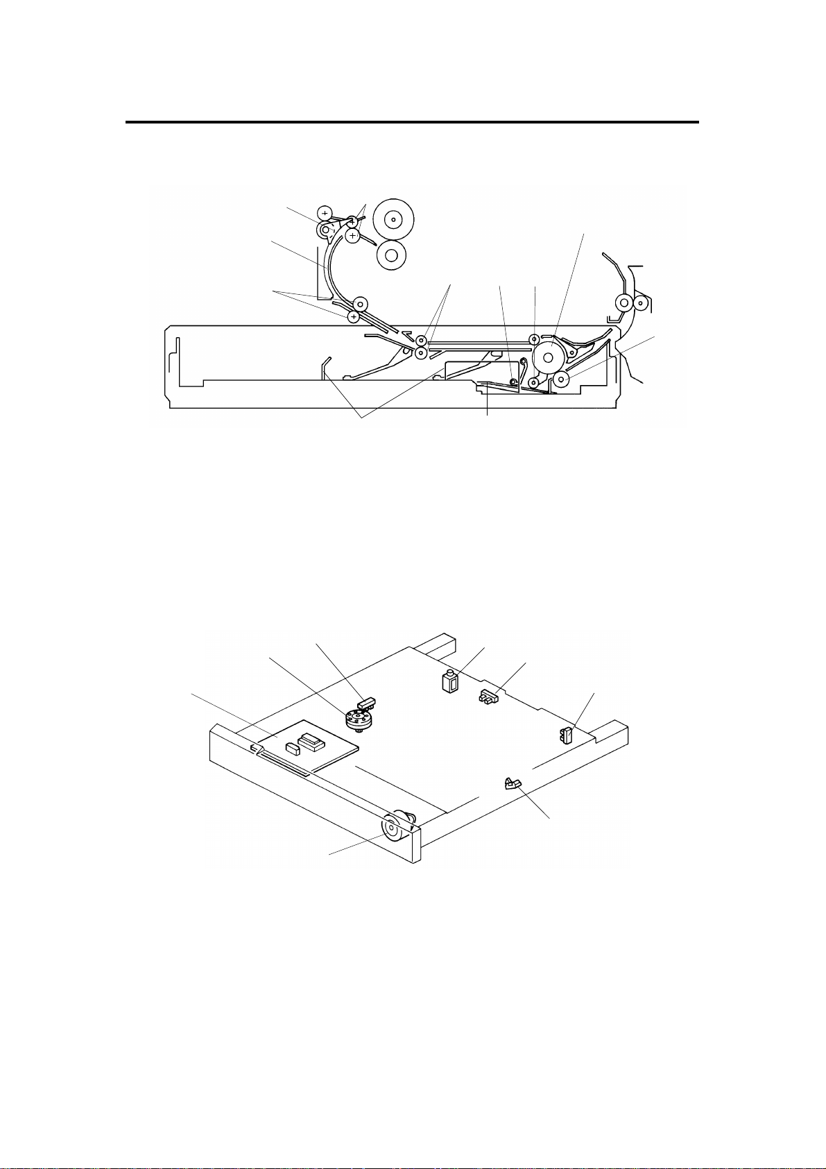
2. COMPONENT LAYOUT
– Mechanical Components –
2
3
1
8
5
4
1011
1. Duplex Gate Roller 7. Paper Flattener
2. Duplex Gate 8. Duplex Feed Roller
3. Turn Guide Plate 9. Friction Roller
4. Transport Roller 10. Duplex Bottom Plate
5. Entrance Roller 11. Jogger Fences
6. Paper End Feeler
– Electrical Components –
2
3
4
7
6
5
9
1
7
8
1. Duplex Main Board 5. Duplex Entrance Sensor
2. Jogger Motor 6. Duplex Paper End Sensor
3. Jogger HP Sensor 7. Duplex Turn Sensor
4. Duplex Gate Solenoid 8. Duplex Feed Motor
2
6
Page 4

1 May 1993 ELECTRICAL COMPONENT DESCRIPTION
3. ELECTRICAL COMPONENT DESCRIPTION
Symbol Name Function Index No.
Motors
M1 Duplex Feed Motor Stepper motor (24 Vdc) drives feed roller
and moves the bottom plate up and down.
M2 Jogger Motor Stepper motor (24 Vdc) drives the jogger
fences to square the paper stack on the
duplex tray.
Solenoid
SOL 1 Duplex Gate
Solenoid
Sensors
S1 Duplex Entrance
Sensor
S2 Duplex Turn Sensor Detects copy in the turn section. 7
S3 Duplex Paper End
Sensor
S4 Jogger Home
Position Sensor
Moves the duplex gate to direct copies to the
duplex tray or to the paper exit.
Detects copy at the entrance. 5
Detects copy in the duplex tray. 6
Detects whether the jogger fences are at
home position.
8
2
4
3
Printed Circuit Board
PCB1 Duplex Main Board Controls all duplex unit functions. 1
Duplex
3
Page 5
POWER DISTRIBUTION AND OVERALL MACHINE CONTROL 1 May 1993
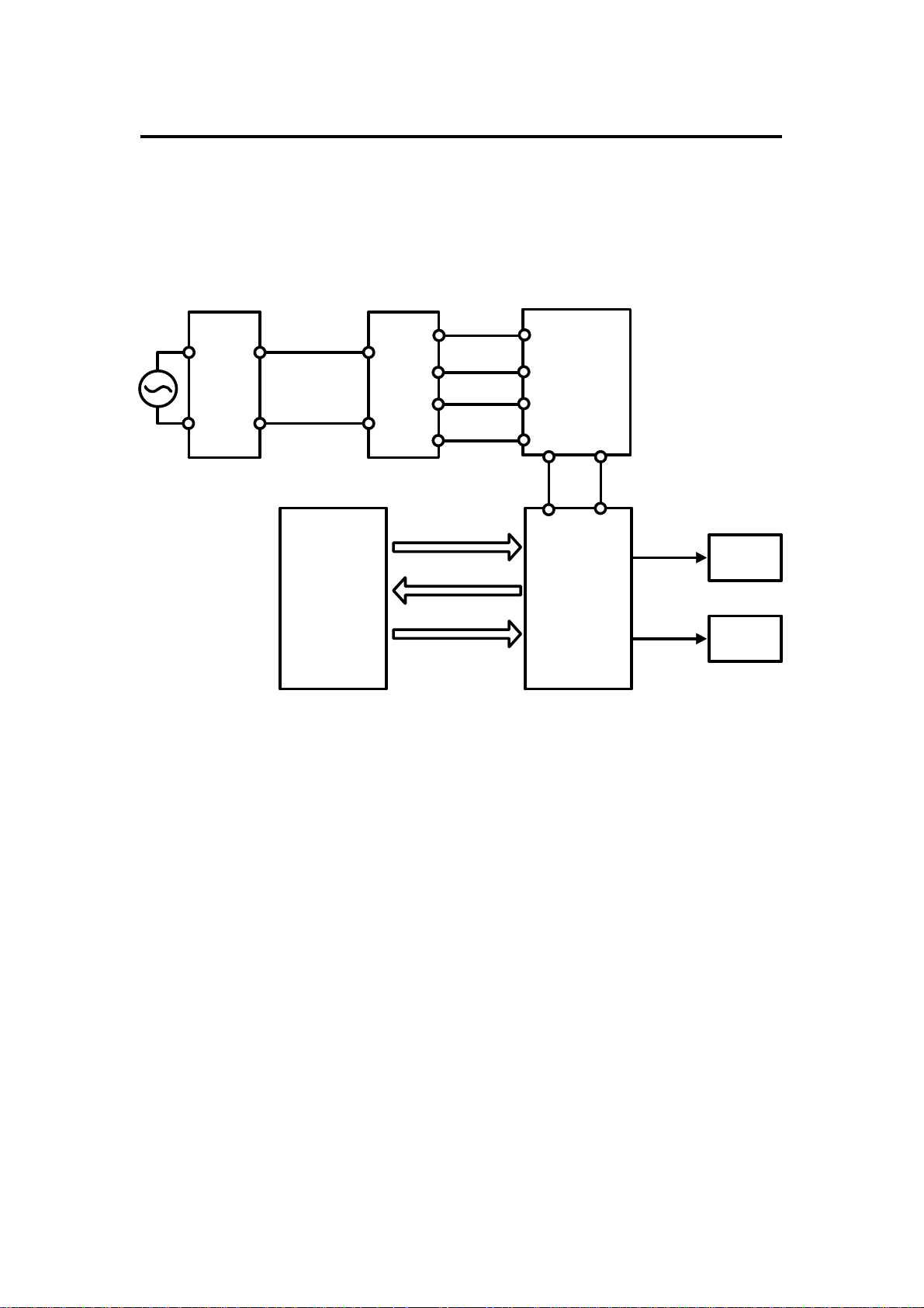
4. POWER DISTRIBUTION AND OVERALL
MACHINE CONTROL
4.1 A110 COPIER
AC Drive Board
(PCB2)
Option Transformer
(TR2)
Option DC Power
Supply Board (PCB6)
115Vac
220/230/240Vac
TXD
RXD TXD
Copier Main Board (PCB1) Duplex Main Board (PCB1)
26Vac
10Vac
Reset Signal
RXD
+24V
(VA)
+5V
(VC)
+24V (VA)
+5V (VC)
Mortors
Solenoid
Sensors
When the main switch is turned on, the option transf orme r receive s wall
outlet ac power thro ugh the ac drive board and outputs 1 0 volt s ac and 26
volts ac to the option dc power supply boa rd. The option dc power supply
board then converts the 10 volts ac to +5 volts an d the 26 volts ac to +24
volts. Then, the +5 volt s and +24 volts are supplied to the duplex main boar d.
The copier main board sends a reset signal to the duplex main board to
initialize the duplex CPU.
The duplex main board supplies dc power to all electrical components in the
duplex unit. All motors and solen oid operate on +24 volts and all sensors
operate on +5 volts.
The duplex main board has its own CPU wh ich con tro ls a ll fun ctio ns in th e
duplex unit. The duplex CPU commun icat es with the copier main board using
a serial interface.
4
Page 6

1 May 1993 POWER DISTRIBUTION AND OVERALL MACHINE CONTROL
4.2 A111 COPIER
AC Drive Board
(PCB2)
Main Transformer
(TR1)
Main DC Power
Supply Board (PCB3)
Mortors
Solenoid
Sensors
115Vac
220/230/240Vac
+24V (VA)
+5V (VC)
Duplex Main Board (PCB1)
RXD
TXD
31Vac
10Vac
Reset Signal
+24V (VA)
+5V (VC)
+24V
(VA)
TXD
RXD
Copier Main Board (PCB1)
+5V
(VC)
When the main switch is turned on, th e main transformer receives wall outlet
ac power through th e ac drive boa rd an d outputs 10 volts ac and 31 volts ac
to the main dc power supply board. The main dc power supply board then
convers the 10 volts ac to +5 volts and the 31 volts ac t o +24 volts. Then, +5
volts and +24 volts are supplied to the duplex main board thro ug h th e copier
main board. The copier main board sends a reset signal to the duplex main
board to initialize the duplex CPU.
The duplex main board supplies dc power to all electrical components in the
duplex unit. All motors and solen oid operate on +24 volts and all sensors
operate on +5 volts.
The duplex main board has its own CPU wh ich con tro ls a ll fun ctio ns in th e
duplex unit. The duplex CPU commun icat es with the copier main board using
a serial interface.
5
Duplex
Page 7
BASIC OPERATION 1 May 1993
5. BASIC OPERATION
[A]
[B] [C]
[D][E][F]
5.1 FIRST S I DE CO PY
When the registration clutch turns on, the duplex gate [A] rotates up to direct
the copy to the duplex unit. The entra nce roller [B] and duplex feed roller [C]
then start to rotate. At the same time , th e duplex bottom plate [D] lowers.
[G]
5.2 DUPLEX STACKI NG
After the copy is delivere d to the dup lex tra y [ E] , th e jogger fences [F] move
inward to square the copy stack, th en move ba ck 10 mm. Af ter t he final copy
is delivered to the tray, the jogger fences remain against the paper stack.
5.3 SECOND S I DE CO PY
Soon after the final copy is squared by the jogger fences, the duplex bottom
plate raises up to the final position and the duplex feed rollers start rotating
counterclockwise (front view) to fee d the cop y to th e rela y rollers [G ]. Second
side copying is then done with the copy following the second feed sta tio n
paper path.
6
Page 8
1 May 1993 DRIVE MECHANISM
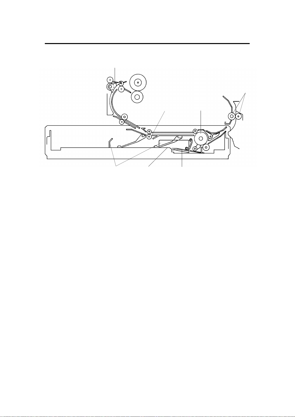
6. DRIVE MECHANISM
[B]
[A]
[C]
[D]
[E]
[F]
Drive is transmitted from the duplex feed motor [A] to the duplex fee d rollers
[B] and the entrance rollers [C] through a series of gears. A rela y gea r in the
copier exit section tran smits drive to th e duplex gate rollers [D] through the
duplex transport gear [E] . A rub be r belt on the en d of the dup lex gate roller
shaft drives the transpo rt rolle rs [F].
The duplex feed motor also drives the duplex bottom plate up and down .
Duplex
7
Page 9
[E]
FIRST SIDE COPY 1 May 1993
7. FIRST SIDE COPY
7.1 FROM COPI E R PAP ER FEED SECTION TO DUPLEX
ENTRANCE ROLLER
[C]
[D]
[B]
[A]
When the copier 1st paper feed clut ch tu rns on , th e jog ge r motor turns on
and drives the three jogger fences into position 10 mm from the edges of the
copy paper. (This position is determin ed by casset te coding.) The registratio n
clutch then turns on and the duplex gate solenoid [A] energizes to raise the
duplex gate [B]. The duplex gate solenoid stays on until first side copying is
finished.
The copy is then directed to the duplex turn guid e, where it is fed by the
transport rollers [C] to the ent ran ce rollers [D]. The leading edge of the copy
activates the duplex entrance sensor [E], which is monitored by the dup lex
CPU to detect misfeeds.
8
Page 10

[B]
[F]
[C]
1 May 1993 FIRST SIDE COPY
7.2 FROM DUPLEX ENTRANCE ROLLER TO DUPLEX TRAY
[G]
[H]
[E]
[B]
[A]
[D]
300 milliseconds after the duplex gate solenoid energizes, the duplex paper
feed motor [A] starts turning cou nterclo ckwise (front view). Gears drive the
duplex feed rollers [B] clockwise and the cam clutch [C] cou nterclo ckwise
(front view). The cam clutch rotat ion lowers th e duplex bottom plate [D].
The tip of the flip mylar [E] mo ves to the left (front view) when the duple x fee d
rollers rotate to feed the copy into the duplex tray. The mylar presse s the
copy against the rollers, ensuring that the trailin g edge of the cop y clears the
guide plate [F]. The paper flat tene rs [G] correct curl on the leading edge of
the copies. The leading edg e of the copy actuates the duplex turn sensor [H],
which is monitored by the duplex CPU to detect misfeed s.
Duplex
9
Page 11

[B]
FIRST SIDE COPY 1 May 1993
7.3 DUPLEX STACKI NG
[A]
2,150 milliseconds after the dup lex tu rn sen sor is actuated by the leading
edge of the copy, the jogg er motor [A] rotates to drive the jogger fences [B]
inward to square the paper sta ck, th en the fen ces move back 10 mm. Afte r
the last copy of the first sid e cop ying run enters the duplex tray, th e fences
remain against the stack.
10
Page 12

1 May 1993 SECOND SIDE COPY
8. SECOND SIDE COPY
[I] [J]
[H]
[G]
[B]
[C]
[F]
[A]
[D][E]
2,350 milliseconds after the dup lex tu rn sen sor is actuated by the leading
edge of the final copy in the first side copy ru n, the duplex fe ed moto r [A]
reverses direction and rotates clockwise (fro nt view), rot at ing the duplex feed
roller [B] counterclockwise (front view). This moves the flip mylar [C] back to
the right (front view). At th e same time th e cam clutch [D] rotates clockwise
(front view), raising the duplex bo tt om pla te [E] .
The paper feed system, which consists of the duplex feed rolle r [B] and the
friction roller [F], feeds only t he top sheet of the stack copies to the relay
rollers [G] in the copier. Aft er that, the second side cop ies fo llow the second
feed station paper path.
After the final copy leave s the dup lex bottom plate, the paper end feeler [H]
drops through a slot in the dup lex bo tt om plate. The paper end actua to r [ I] ,
which is on the same shaft as th e pa pe r end fee ler, pivots into the duplex
paper end sensor [J], sen din g a High signal to the main board to stop the
next paper feeding cycle.
11
Duplex
Page 13

0
1750
2000 2500 3000 3500 4000 4500 5000 5500
1750 1750
2000 2000
50 m sec 50 m sec
2100 m sec 2100 m sec
3425
3425
31103110
200 m sec
450 m sec
J1 J1
J3
J2 J2
J3
2000
2075
1750
100
(A110 copier)2500
(A111 copier)2445
1750
1750
Start Key
Main Motor
DUPLEX PAPER FEED AND MISFEED DETECTION TIMING 1 May 1993
9. DUPLEX PAPER FEED AND MISFEED
DETECTION TIMING
Timing Pulse
(4 m sec/pulse)
1st Feed Clutch
Registration
Clutch
Jogger Motor
Duplex Entrance
Sensor
Duplex Turn
Sensor
Duplex Gate
Sol.
Duplex Feed
Motor
The duplex entrance sensor and the duplex turn sensor monitor the
movement of the pape r through the paper path in duple x mode . If the duplex
CPU determines that a misfeed exists, the duplex CPU se nds a misfeed
signal to the copier CPU, and the Check Pa pe r Pat h and th e Misfeed
Location indicators turn on . Whe n th e main switch is turned on, the CPU
checks the duplex entrance sensor for initial misfeed. During the first side
copy cycle, the duplex CPU performs thre e kind s of misfe ed detection:
J1: Checks whether the duplex en tra nce sensor is actuated within 1, 11 0
pulses (about 4.4 second s) aft er the registration clutch tu rns on . (The
Misfeed Location indicator "E" turns on.)
J2: Checks whether the duplex turn sen sor is actuated within 1,425
pulses (about 5.7 second s) aft er the registration clutch tu rns on . (The
Misfeed Location indicator "E" turns on.)
J3: Checks whether the copy pape r passes through the duplex ent rance
sensor 525 pulses (2.1 seconds) a ft er the duplex turn sensor has
been actuated. (The Misf ee d Lo cat ion indicator "E" turns on. )
In the second side copy cycle , th e misfeed detection timing is same as the
one in the second feed station copying.
12
Page 14

1 May 1993 INSTALLATION PROCEDURE
10.INSTALLATION PROCEDURE
10.1 ACCESSORY CHECK
Check the quantity and cond itio n of the accessories in the box according to
the following list:
1. Turn Guide Plate ...................... ...................... ................................ ..1
2. Roller .... ...................... ................................ ...................... ................3
3. Connector Bracke t .............. .. ...................... ...................... ................1
4. Shoulder Screw .................... ................................ ...................... ......2
5. Philips Pan Head Screw - M3 x 6 ........................... .. .. .... .. .. .. .. .. .. .... ..4
6. Tray Cover .............. ...................... ................................ ....................1
7. Multi Lingual Decal (Europe only) ..... .. .. .. .... .. .. .. .. .. .. .... .. .. .. .. .. .. .... .. .. ..1
8. Duplex Harness......................... ................ .. .. .. ................ .. .. .. ............1
NOTE: 1. When the duplex unit is installed on the copier, the DC Power
Supply Unit (option) is required. (A11 0 copier on ly)
2. When installing the DC Power Supply Unit, please ref er to the
installation procedu re enclosed with it.
13
Duplex
Page 15

INSTALLATION PROCEDURE 1 May 1993
10.2 INSTALLATION PROCEDURE
[A]
[C]
[B]
1. Turn off the main switch and un plu g the copier power supply cord.
[D]
2. Install the optional power supply unit (A110 copier only).
Refer to the installa tion procedure enclosed with the power supply unit
(A525).
3. Remove the strips and styrofoam blo cks [A] .
4. Open the exit unit [B] and remove it (2 screws).
5. Using pliers, bend the flaps [C] all the way un der t he fusing bottom plate
[D]. Be careful not to bre ak them off.
14
Page 16

[D]
[D]
1 May 1993 INSTALLATION PROCEDURE
[A]
[A]
[B]
[B]
[C]
[C]
[E]
6. Remove the exit paper guide [A] (1 screw), and remove the stubs [B] with
nippers and reinstall the exit pape r guide.
7. Remove the upper paper guide [C] on th e exit unit (2 scre ws) and remove
the stubs [D] with nippers.
Duplex
8. Install the three rollers [E] on the exit unit as sho wn.
9. Reinstall the upper paper gu ide plate [C] on the exit unit.
15
Page 17

INSTALLATION PROCEDURE 1 May 1993
[A]
[A110 copier]
[B]
[C]
[D]
10. While pushing up the dup lex ga te lever [A], install the turn guid e plate [B]
(2 screws).
11. Reinstall the exit unit (2 screws).
12. Remove the 1st paper tray from the copie r.
13. Remove the rear cover (4 screws).
14. Remove the power supply cord bra cket [C] (2 screws) an d sup po rt
bracket [D] (1 screw) (A110 copier only).
16
Page 18

[B]
1 May 1993 INSTALLATION PROCEDURE
[C]
[A]
[D]
15. Remove the duplex connecto r cover plate [A] (2 screws).
NOTE: The cover plate can be thrown awa y.
16. Secure the duple x harness connector (8P/Bla ck) [B] to th e connector
bracket [C] as shown (2 screws).
17. Secure the connector bracket to the rear frame (2 shoulder screws).
NOTE: When installing the bracket , make sure that the cut-out [D] on the
bracket faces up as shown.
18. Reinstall the power supply cord bracket and support bracket (A110
copier only).
Duplex
17
Page 19

[A111 copier]
[E]
[G]
[F]
INSTALLATION PROCEDURE 1 May 1993
[B]
[A]
[A110 copier]
[C]
[D]
CN101
[B]
[A]
[F]
[G]
[H]
[I]
19. Connect the duplex harness conn ect or (4P/Brown) [A] to CN151 on the
main board [B].
20. Connect the duplex harness conn ect or (4P/White) [C] to CN101 on the
optional power supply unit [D] (A110 copier only).
21. Connect the duplex harness conn ect or (4P/White) [E] to CN150 on the
main board (A111 copier only).
22. Set the duplex harness [F] into the wire clamps [G] as shown.
23. Reinstall the rear cover (4 screws).
24. Insert the duplex unit into the copier.
25. Plug in the copier power supply cord and turn on the main switch.
26. Check the operatio n of the duplex unit.
27. Attach the tray cover [H] on the paper tray [I] as shown.
NOTE: Explain to the customer how to install the tray cover.
18
Page 20

[I]
[G]
1 May 1993 REPLACEMENT AND ADJUSTMENT
11.REPLACEMENT AND ADJUSTMENT
11.1 DUPLEX TRAY REMOVAL
[C]
[B]
[A]
[F]
[H]
1. Pull the duplex tray [A] out from the copier.
2. Remove the side inner cover [B] (3 screws).
3. Remove the front inner cover [C] (2 screws).
4. Unhook the pressure spring [D] from the paper lift arm [E] and the
eccentric cam.
5. Remove the clamps [F] with a pair of pliers.
[F]
[E]
[D]
6. Disconnect CN702, CN704, and CN706 [G] from the main board.
7. Disconnect the sensor connector [H] from th e jog ger h ome posit ion
sensor.
8. Remove the duplex unit [I] (4 screws and groun din g wire) fro m the tray.
NOTE: Hold both sides of the duplex unit frame when lifting the duple x
unit out of the tray.
19
Duplex
Page 21

[C]
[E]
[B]
[F]
REPLACEMENT AND ADJUSTMENT 1 May 1993
[D]
[H]
[G]
[A]
– Installation –
1. When placing the duplex unit back into the tray, hold up the bot to m plat e
[A] so that the mylar brackets [B] fit un der it as shown .
2. Hook the pressure spring [C] to the eccen tric cam [D] and the paper lift
arm [E] as shown.
NOTE: When installing the duple x unit , make sure of the following:
a) Positioning pin [F] fit s through hole [G] in the side plat e.
b) The sensor harness [H] is clamped correct ly a nd is not cau gh t
under the unit frame.
20
Page 22

[B]
1 May 1993 REPLACEMENT AND ADJUSTMENT
11.2 JOGGER MOTOR AND JOGGE R HOME POSITION
SENSOR REPLACEMENT
[D]
[E]
[C]
[A]
1. Remove the duplex tray.
2. Remove the front and side inner covers.
– Jogger Motor Replacement –
3. Disconnect CN705 [A] from the duplex main board.
4. Replace the jogger motor [B] (2 screws).
– Jogger Home Position Sensor Replacem ent –
3. Disconnect the sensor connector [C].
4. Remove the sensor bracket [D] (1 screw).
5. Remove the sensor [E] fro m t he bracke t an d rep lace it (1 screw).
Duplex
21
Page 23

REPLACEMENT AND ADJUSTMENT 1 May 1993
11.3 TURN SENSOR REPLACEMENT
[A]
[C]
[B]
[D]
1. Remove the duplex tray.
2. Raise the upper and lower paper gu ide s [A] all the way up.
3. Disconnect the turn sensor connector [B].
4. While lifting the sensor act ua to r [ C], remove the sensor [D] (1 screw).
22
Page 24

[C]
1 May 1993 REPLACEMENT AND ADJUSTMENT
11.4 FEED MOTOR REPLACEMENT
[B]
[A]
1. Remove the duplex unit from the tray. (S ee Duplex Unit Removal.)
2. Remove the paper feed motor bracke t [A ] (2 screws).
3. Replace the feed motor [B] (2 screws).
NOTE: When installing the paper f ee d mot or, make sure that the bushing
[C] is properly positioned bet wee n the bracket and the motor as
shown.
Duplex
23
Page 25

REPLACEMENT AND ADJUSTMENT 1 May 1993
11.5 PAPER END SENSOR REPLACEME NT
[B]
[C]
1. Remove the duplex unit from the tray. (S ee Duplex Unit Removal.)
2. Remove the paper end sensor bracket [A] (1 screw).
3. Disconnect the sensor connector [B].
4. Replace the sensor [C] (1 screw).
[A]
24
Page 26

1 May 1993 REPLACEMENT AND ADJUSTMENT
11.6 ENTRANCE SENSOR REPLACEMENT
[C]
[[A]
[B]
1. Remove the duplex unit from the tray. (S ee Duplex Unit Removal.)
2. Turn over the duplex unit as shown.
3. Remove the entrance sensor bracket [A] (1 screw).
4. Disconnect the sensor connector [B].
5. Replace the sensor [C].
25
Duplex
Page 27

REPLACEMENT AND ADJUSTMENT 1 May 1993
11.7 GATE SOLENOID REPLACEMENT
[C]
[D]
[A]
[B]
[E]
1.Remove the duplex unit from th e tray. (See Duplex Unit Removal.)
2. Replace the gate solen oid [A] (1 screw).
NOTE: When installing a new solenoid, make sure of the following:
a) Positioning pin [B] fits into the ho le [C] on the gate solen oid
actuator.
b) Spring [D] is hooked to bracket [E] .
26
Page 28

[D]
1 May 1993 REPLACEMENT AND ADJUSTMENT
11.8 FRICTION ROLLER REPLACEMENT
[A]
[B]
[C]
1. Remove the duplex unit from the tray. (S ee Duplex Unit Removal.)
2. Turn over the duplex unit as shown.
3. Unhook the springs [A] fro m t he roller bracket [B].
4. Remove the lock pin [C] and the roller assembly.
5. Remove the roller [D] (1 snap-ring and shaft) from the bracket and
replace it.
NOTE: This friction roller has a one-way clutch. Be sure to install the
roller so that it rotates in the direction of the arrow. (See
illustration.)
Duplex
27
Page 29

REPLACEMENT AND ADJUSTMENT 1 May 1993
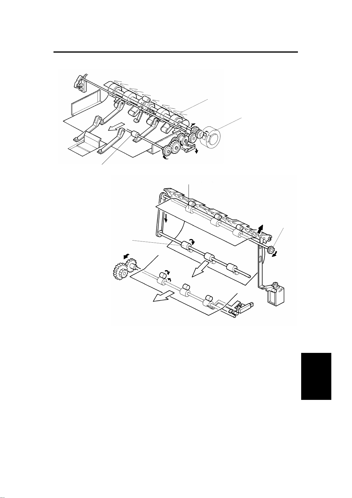
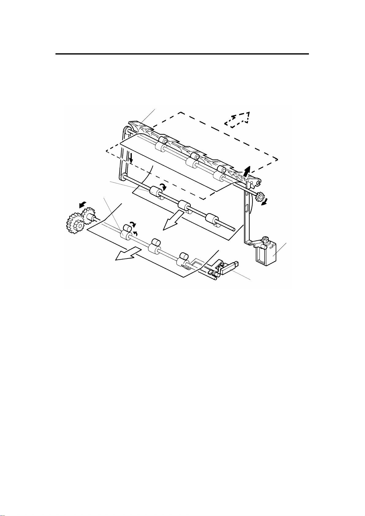
11.9 FEED ROLLER REPLACEMENT
[F]
[D]
[G]
[M]
[C]
[E]
[L]
[K]
[J]
[I]
[H]
1. Remove the duplex unit from the tray. (S ee Duplex Unit Removal.)
2. Remove the feed motor. (See Feed Motor Replacement.)
3. Remove the drive gear [A] (1 E-ring) and th ree idle ge ars [B ] (1 pa ralle l
pin [C]).
4. Remove the E-ring [D] and the up pe r pap er gu ide plate stopper [E] (1
shoulder screw).
5. Remove the upper and lower guid e pa pe r plates [F].
6. Remove the paper end feele r shaft [G] (1 E-ring).
[A]
[B]
7. Remove the E-ring [H] on the fron t side of the feed roller shaft [I].
8. Remove the feed roller shaft (2 bushin gs).
9. Remove the feed support roller [J], flatter [K], paper retainer [L]; then,
replace the feed roller [M] (1 E-ring and parallel pin per rolle r).
28
 Loading...