

Page 1

SORTER
Page 2

1 May 1993 SPECIFICATIONS
1. SPECIFICATIONS
Number of Bins: 10 bins
Paper Size for Bins: Maximum A3, 11" x 17"
Minimum A5, 51/2" x 81/2"
Paper Weight: 64 to 90 g/m2 (17 to 24 lb)
Bin Capacity: Sort/Stack 20 sheets / A4, 81/2" x11"
Mode 15 sheets / B4, 81/2" x 14"
10 sheets / A3, 11" x 17"
Top Bin Capacity:
(Non-Sort/Stack Mode)
Power Source: +5 volts and +24 volts from the copier
Power Consumption: 7.7 W
Dimensions:
(W x D x H)
Weight: 7.5 kg (16.5 lb)
100 sheets (all sizes)
402 mm x 443 mm x 217 mm
(15.8" x 17.4" x 8.5")
Sorter
1
Page 3
6
5
COMPONENT LAYOUT 1 May 1993
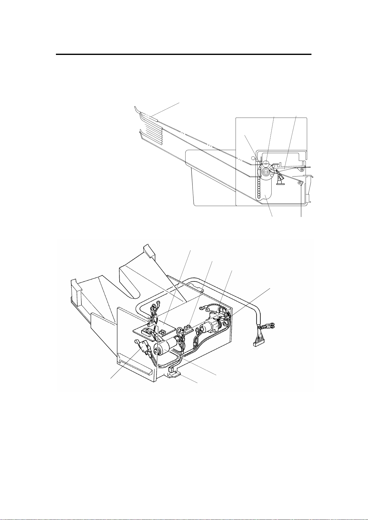
2. COMPONENT LAYOUT
– Mechanical Components –
1
1. Bin
2. Transfer Wheel
3. Exit Roller
4. Upper Paper Guide
5. Lower Paper Guide
6. Bin Guide
– Electrical Components –
3
2
6
1
2
3
4
4
5
7
1. Sorter Main Board 5. Sorter Switch
2. Paper Sensor 6. Bin Drive Mot or
3. Wheel Switch 7. Home Position Switch
4. Roller Drive Motor
2
Page 4

1 May 1993 ELECTRICAL COMPONENT DESCRIPTIONS
3. ELECTRICAL COMPONENT DESCRIPTIONS
Symbol Name Function Index No.
Motors
M1 Roller Drive Motor DC motor that energizes to drive the lower
exit rollers.
M2 Bin Drive Motor Reversible DC motor that energizes to move
the bins up or down.
Switches
SW1 Wheel Switch Detects the rotation of the transfer wheel
and stops it in the correct position.
SW2 Sorter Switch Reed switch that becomes activated when
the sorter is in the proper position (aligned
next to the copier). Also works as a jam
reset switch for the sorter.
SW3 Home Position
Switch
Informs the CPU that all the bins are lowered. 7
4
6
3
5
Sensor
S1 Paper Sensor Serves as the misfeed sensor for the sorter
and also sets exit roller and bin drive timing.
Printed Circuit Board
PCB1 Sorter Main Board Serves as the communication board
between the copier main board and the
sorter.
2
1
Sorter
3
Page 5
OVERALL MACHINE CONTROL 1 May 1993
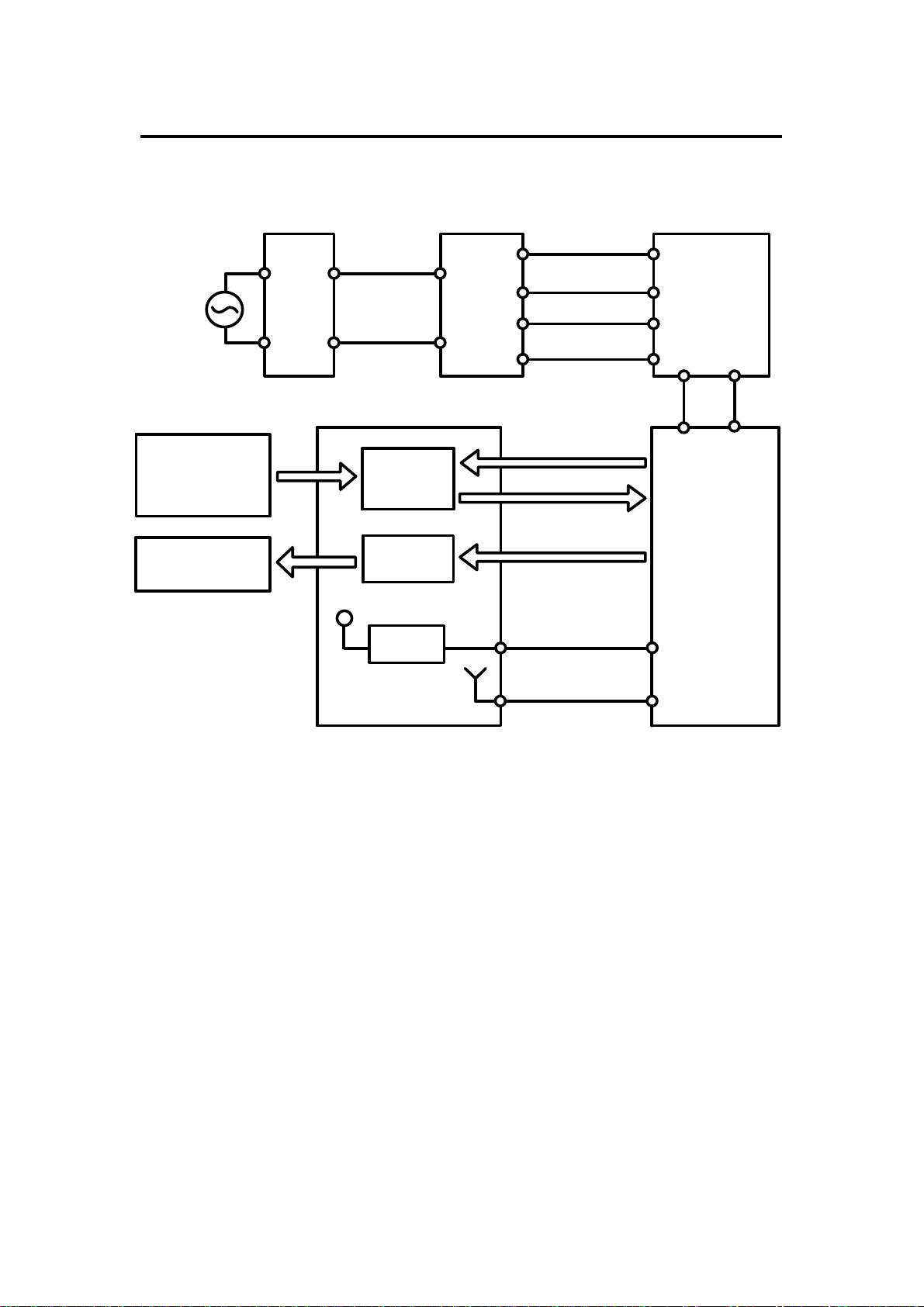
4. OVERALL MACHINE CONTROL
Paper Sensor
Sorter Switch
Home Position Switch
Wheel Switch
Roller Drive Motor
Bin Drive Motor
AC Drive Board
(PCB2)
+12V
115Vac
220/230/240Vac
Data Select
IC
Drive IC
Regulator
IC
Main Transformer
(TR1)
Scan Signal
Scan Output Signal
Sorter Drive Signal
+24V(VA)
26Vac (A110 copier)
31Vac (A111 copier)
10Vac
Main DC Power
Supply Board (PCB3)
+24V
(VA)
+5V
(VC)
+5V(VC)
Sorter Main Board (PCB1)
Copier Main Board (PCB1)
The copier main board provide s +24 volt s (VA) and +5 volts (VC) to the sorter
main board. +24 volts powers the roller drive motor, and +5 volts po wers all
sensors and switches. Also, +24 volts is changed to +12 volts by the
regulator IC, which powers the bin drive motor.
The copier main board controls t he drive and che cks t he stat us of the sorte r
via the sorter main board. The copie r main bo ard send s the scan sign als to
the data selected IC on the sorter main board. After receiving the scan
signals, the data select IC outputs th e sta tu s of th e sensor an d switch es as
the scan output signal.
The copier main board also sends the sorte r drive signal to the drive IC on
the sorter main board. Af te r receiving the drive signal, the drive IC turns on
the appropriate motors.
4
Page 6

1 May 1993 BASIC OPERATION
5. BASIC OPERATION
– Clear Mode –
When the main switch of the copier is turned on, the sorter automatically
assumes the clear mode. In this mo de, all copies are stacked on the first bin.
The sorter also assumes the clear mod e whe n eit he r the inte rrupt mode or
the manual feed mode is selected.
Sorter operation be gin s wh en a copy act ua te s t he copie r e xit sen sor. At this
time, the roller drive motor energizes. Whe n the paper exits onto the sorte r
bin, the paper sensor is de-activated and the roller drive motor is then
de-energized. The copier main board monitors the paper sensor through the
sorter main board to check for pape r misfee ds.
– Sort Mode –
Pressing the Sorter ke y once shifts the copier to the sort mode . In this mode,
all copies of the first original are delivered to separa te bins sta rtin g from the
top. The copies of the second original are delivered to th e same bins, but
starting from the bottom. The cop ies of the third origin al sta rt from the top and
so on. The bin drive motor turns on to advance th e bin one step , 25 0
milliseconds after the copy has gone th rou gh the pape r sen sor. If th e Cop y
Quantity, Clear/St op , Book Copy, or Sorter key is pressed durin g th e sort
mode, all bins shift to the ho me po sition.
– Stack Mode –
Pressing the Sorter ke y twice shif ts the copier to the stack mode. In th is
mode, all copies of the first origina l are de livere d to the first bin , all copies of
the second original are delivere d to the secon d bin , an d so on. The bin drive
motor turns on to advance the bin one ste p, 250 milliseconds after the last
copy of the original has gone through the pap er sen sor. If th e Sorter key is
pressed during stack mode, all bins shif t to home posit ion.
Sorter
5
Page 7
EXIT ROLLER DRIVE 1 May 1993
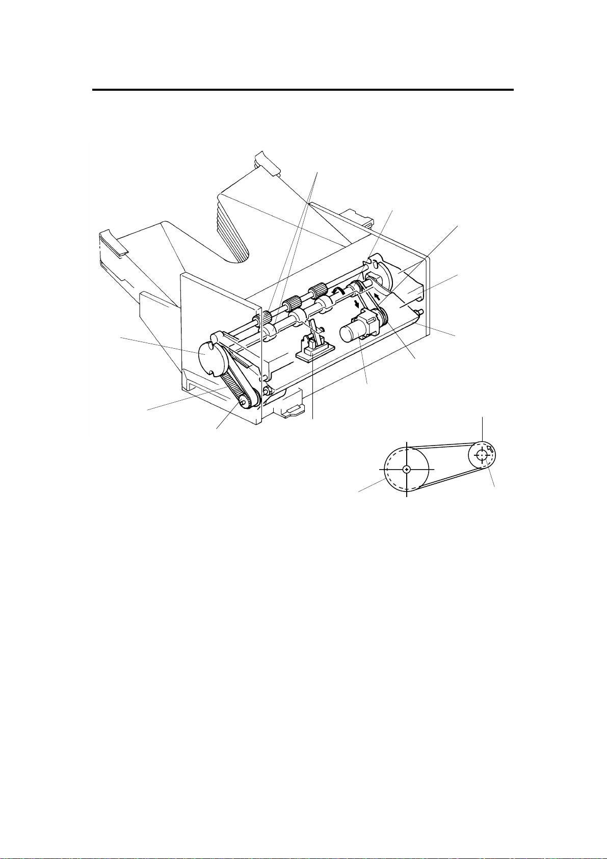
6. EXIT ROLLER DRIVE
6.1 ROLLER DRIVE MECHANISM
[A]
[I]
[D]
[J]
[F]
[L]
[C]
[G]
[B]
[H]
[L]
F: Transfer Wheel
G: Bin Drive Belt
H: Bin Drive Pulley
I: Exit Roller Pulley
J: Upper Paper Guide
K: Lower Paper Guide
L: Roller Drive Motor Pulley
The exit rollers [A] take over pape r tra nsp ort from the copier. When the copy
paper actuates the copier exit sensor, the exit rollers start rotatin g. The exit
rollers continue to rotate for 2 50 millise con ds af te r the copy pape r has go ne
through th e pa per sensor [B].
[K]
[H]
[E]
The roller drive motor [C] rotates the lower exit roller via the rolle r drive belt
[D]. The shaft of the lower exit roller is a cylindrical cavity type which rotates
around the transfer whee l shaf t [E]. The paper sensor is positioned just in
front of the exit rollers. The paper sensor detects misfeeds in the sorter.
6
Page 8
1 May 1993 EXIT ROLLER DRIVE
6.2 ROLLER DRIVE CIRCUIT
Copier Main
Board
Sorter Main Board (PCB1)
CN2
(PCB1)
Paper Sensor
Roller
Drive
M
CN53-1
CN53-2
CN102-5
CN102-4
CN102-6
CN102-13
CN102-7
+5V
+24V
+5V
+24V
CN101-3
Scan Signal
Data
Select
0V
0V
IC
Drive
IC
Scan Output
Drive Signal
Clock Pulse
CN101-4
CN101-5
CN101-6
CN101-7
CN101-8
CN101-9
CN126-1
CN126-2
CN126-3
CN126-10
CN126-4
CN126-5
CN126-6
To turn on the roller drive motor, the copier main board sends a drive signal
to the drive IC on the sorter main board. Aft er receiving the drive signal, the
drive IC drops CN102-7 from +24 to 0 volt to turn on the roller drive moto r.
When the paper sensor is actu at ed , CN102-13 drops to LOW. The cop ier
main board outputs th ree scan signals to the data select IC. The sta tus of the
sensor changes the resulting scan output signal. Using the scan output
signal, the copier main board dete rmine s the stat us of the senso r. For safety
reasons, the CPU limits the operation time of the roller drive motor to 5
seconds.
Sorter
7
Page 9

[E]
[C]
BIN DRIVE 1 May 1993
7. BIN DRIVE
7.1 BIN DRIVE MECHANISM
[E]
[D]
[B]
G : Exit Roller
H : Upper Paper Guide
I: Lower Paper Guide
[F]
[A]
[G]
[G]
[D’]
[B’]
[H]
The bin drive mechanism moves
the bins up and down to receive
copies under the dire ctio n of the
copier CPU. The main
components in this mechanism
are the bin drive motor [A], two
transfer wheels [B, B ’] , the wheel
switch [C], and the bins
themselves.
Pins on either side of each bin are
inserted into slots called bin
guides [D,D’]. The bins slide up
and down in the bin guides. The
bins sit on each other with the
lower bin resting on the
permanently-mounted 10th bin.
The upper and lower paper guides
pivot up and down depending on
the height of the bin to be picked
up or released.
[I]
[B]
8
Page 10

OFF
OFF
1 May 1993 BIN DRIVE
The home position switch [E]
informs the CPU when all the bins
are lowered.
To move the bins up, the bin drive
motor turns clockwise (as viewed
from the front). A timing belt [F]
turns the transfer wheels.
The transfer wheels have two
slots in them 180 degrees ap art .
As the transfer wheels turn, these
slots engage the bins and lift them
up. Each time the transfer wheels
turn 180 degrees, they raise one
bin.
To move the bins down, the CPU
reverses the bin drive motor and
the above processes reverses.
The CPU monitors the position of
the bins through pulses generated
by the wheel switch and the
actuator cam [J]. The actu at or
cam has two flat sides that are
180 degrees apart and is mounted
behind the rear transfer wheel. A
pulse is generated each time one
of the lobes of the actu ator cam
passes the wheel switch.
[B]
[J]
[C]
ON
Sorter
9
Page 11

BIN DRIVE 1 May 1993
7.2 BIN DRIVE CIRCUIT
Copier Main
Board
Home Position Switch
T51
CN102-11
CN102-1
T52
Wheel Switch
T53
CN102-12
CN102-2
T54
Sorter Main Board (PCB1)
+5V
0V
+5V
0V
Data
Select
IC
Scan Signal
Scan Output
CN101-3
CN101-4
CN101-5
CN101-6
CN2
CN126-1
CN126-2
CN126-3
CN126-10
(PCB1)
Down
Drive Signal
0V
+12V
0V
Drive
IC
Clock Pulse
CN101-7
CN101-8
CN101-9
CN126-4
CN126-5
CN126-6
Bin
Drive
M
CN51-1
CN51-2
CN102-8
CN102-9
Up
+12V
0V
0V
To turn on the bin drive motor, the copie r ma in board sends drive signals to
the drive IC on the sorter main board. After receivin g the drive signa ls, the
drive IC either raises CN102-8 or CN102-9 to +12 volts. This tu rns on the bin
drive motor which respectively moves a bin up or down. The sorter main
board monitors the output of bot h sorter switches through the data select IC.
When either the home position switch or wheel switch is actuat ed, CN102-11
or CN102-12 drops to LOW. The copier main board outputs three scan
signals to the data select IC. The stat us of the swit che s chan ges the resulting
scan output signal. Using the scan output signal, the copier main board
determines the status of the switch.
The CPU monitors the on-time of the bin drive motor to dete ct a malfun ctio n
of the bin drive motor. If the bin drive mot or con tin ue s to rot at e more than
twelve seconds, the CPU stops machine operation.
10
Page 12

1 May 1993 MISFEED DETECTION
8. MISFEED DETECTION
J1 J2 J1 J2
2942
2942
Paper Sensor
2.75 sec ((A4 sidewise)
2.80 sec (LT sidewise)
2.75 sec (A4 sidewise)
2.80 sec (LT sidewise)
In addition to being used for th e exit roller and bin drive timin g, the paper
sensor checks for a misfeed in th e sort er. The copier CPU checks whether
the paper sensor is actuated within 942 pulses (3.8 seconds) after the
registration clutch turn s on (at 2,000 pulse s). (J1: Pap er Sensor ON Check)
Also, the copier CPU starts a timing cycle when the paper sensor is actuated.
Then, at 2.75 (A4 sideways) or 2.8 0 (Le tt er sideways) seconds, the CPU
checks whether the cop y pap er ha s passed through the paper sensor. (J2:
Paper Sensor OFF Check)
In misfeed condition, the "Check P aper Pa th " and "Misf eed Lo cat ion "
indicators lights and copie r o peration is inhibited. To recover the sort er from
the misfeed condition, th e sort er has to be slide awa y from th e cop ier, then,
after misfed paper removal, ret urned to its original position.
11
Sorter
Page 13

INSTALLATION PROCEDURE (for Machine Code: A110/A111) 1 May 1993
9. INSTALLATION PROCEDURE
(for Machine Code: A110/A111)
9.1 ACCESSORY CHECK
Check the quantity and cond itio n of the accessories in the box according to
the following list:
1. Magnet Catch..................................................................................1
2. Sorter Holder Bracket............ .. .................... .. ..................................1
3. Sorter Holder Bracket Cover......... .. .. .. .. .. ................ .. ................ .. ....1
4. Philips Pan Head Screw - M4 x 8....................................................8
5. Philips Pan Head Screw - M4 x 8....................................................1
6. Screw M4 x 8............... .. ............................................................ .. ....1
7. Snap Ring........................................................................................1
8. Toothed Washer..............................................................................1
9. Spring Washer.................................................................................1
10. Interfa ce Harness ............................................................................1
12
Page 14

[F]
1 May 1993 INSTALLATION PROCEDURE (for Machine Code: A110/A111)
9.2 INSTALLATION PROCEDURE
[C]
[A]
[B]
[G]
[D]
[I]
[H]
[E]
NOTE: Do not grasp the sorter by the top cover and stay as shown by [A].
Hold both sides of the sorter as shown by [B]. This is to prevent
anti-static brush [C] damage.
1. Turn off the main switch and un plu g the power supply cord of the copier.
2. Remove the strips and styrofoam blo cks [D].
3. Remove the receiving tray [E].
4. Remove the rear cover [F] (4 screws).
5. Remove the caps [G] on the upper left side cover with the pliers.
6. Install the magnet catch [H] on the exit unit [I] (2 scre ws).
13
Sorter
Page 15

[H]
INSTALLATION PROCEDURE (for Machine Code: A110/A111) 1 May 1993
[B]
[C]
[A]
[D]
[G]
[F]
[E]
7. Install the sorter holder bracket [A ] (3 screws) so th at the two ho les [B ] on
the bracket align with the hole s [C] on the copie r f rame as shown .
8. Install the sorter [D] on th e sort er ho lder bracket (1 snap ring) as shown .
9. Remove the ac harness [E] from the wire clamp [F] as shown .
10. Install the sorter harne ss bracket [G] with the harness (2 screws).
11. Reinstall the ac harness into the wire clamp.
12. Install the sorter holde r bracket cover [H] (1 screw).
14
Page 16

1 May 1993 INSTALLATION PROCEDURE (for Machine Code: A110/A111)
[D]
[C]
[F]
[E]
[I]
[H]
[G]
[B]
[A]
13. Connect the sorte r dc harness [A] (10P/Brown) to the interface harness
connector [B].
14. Connect the interfa ce harness connector [C] to CN126 on the main board
[D].
15. Set the interface harness [E] into the clamps [F] as shown.
16. Secure the grounding wire [G ] (1 screw, too th ed wa she r [H], and spring
washer [I]) on the bottom plate as shown.
17. Plug in the copier power supply cord.
18. Change the SP71 data to "1" (sorter instruction).
19. Reinstall the rear cover and turn on the main switch.
20. Check the operatio n of the sorter.
Sorter
15
Page 17

PREPARATION FOR TRANSPORTATION 1 May 1993
10.PREPARATION FOR TRANSPORTATION
CAUTION: When removing and transporting the sor ter , be ca re ful not
to carry it in a vertical position as the bins will become
dislocated.
CAUTION: Before moving the sorter, be sure to prepa re it for
transportation as follows. The sorter may be badly
damaged if it is moved without proper preparation.
1. If the bins are not at the home position, tu rn on the main switch of the
copier to move the bins to the home position.
2. Secure the bins with strips of tape as shown in the illu stra tio n.
3. Remove the sorter from the copier. (See the Installation Procedure
[Sorter] section.)
16
Page 18

[D]
[M]
1 May 1993 ROLLER DRIVE BELT REPLACEMENT
11.ROLLER DRIVE BELT REPLACEMENT
[E]
[F]
[B]
[J]
[I]
[G]
[K]
[L]
[C]
[H]
[A]
1. Remove the front covers [A] (5 screws) and rear cover [B] (2 screws).
2. Lift off the top cover [C].
3. Remove the top stay [D].
NOTE: Be sure that the discharge brush on the top stay is facing the exit
side of the sorter when reinsta lling it.
4. Lift the upper paper guide [E] up and out of position.
5. Lift the lower paper guide [F] out of position and tu rn it ove r t o remove th e
roller drive belt [G].
NOTE: Be careful not to damage the sorte r home posit ion swit ch
actuator [H] when reassemb ling.
6. Remove the transfer wheel [I], spacer [J], pin [K] and bushing [L] (1
C-ring).
7. Slide the wheel shaft [M] towards the front and remove the roller drive
belt.
17
Sorter
Page 19

BIN GUIDE LUBRICATION 1 May 1993
12.BIN GUIDE LUBRICATION
A
B
A
B
C
B
C
B
C
B
C
Grease 501
[A]
C
Grease 501
[B]
[B]
1. Remove the lower paper guide. (See Roller Drive Be lt Rep lacement
section.)
2. Remove all bins [A] from the bin guide s [B] .
3. Apply Grease 501 to the groo ves of the bin gu ide s.
NOTE: There are three kinds of bin s. Therefore, when installin g the bins,
be sure that they are installed in the correct order.
18
Page 20

1 May 1993 BIN GUIDE LUBRICATION
Table of Contents
SPECIFICATIONS 1
COMPONENT LAYOUT 2
ELECTRICAL COMPONENT DESCRIPTI ONS 3
OVERALL MACHINE CONTROL 4
BASIC OPERATION 5
EXIT ROLLER DRIVE 6
ROLLER DRIVE MECHANISM 6
ROLLER DRIVE CIRCUIT 7
BIN DRIVE 8
BIN DRIVE MECHANISM 8
BIN DRIVE CIRCUIT 10
MISFEED DETECTION 11
INSTALLATION PROCEDURE (for Mach ine Code A110/A111) 12
ACCESSORY CHECK 12
INSTALLATION PROCEDURE 13
PREPARATION FOR TRANSPORTATION 16
ROLLER DRIVE BELT REPLACEMENT17
BIN GUIDE LUBRICATION 18
19
Sorter
 Loading...