

Page 1

DOCUMENT FEEDER
Page 2

1 May 1993 SPECIFICATIONS
1. SPECIFICATIONS
Original Size and Weight: – Thin original mode –
Maximum A3/11" x 17"
Minimum B6/51/2" x 81/2"
Weight 41 to 128 g/m2 (11 to 34 lb)
– Thick original mode –
Maximum A3 / 11" x 17"
Minimum B6 / 51/2" x 81/2"
Weight 52 to 128 g/m2 (14 to 34 lb)
– Auto reverse mode –
Maximum A3 / 11" x 17"
Minimum B6 lengthwise /
51/2" x 81/2" lengthwise
Weight 53 to 105 g/m2 (14 to 28 lb)
Original Feed: Automatic feed — ADF mode
Manual feed one by one — SADF mode
Original Table Capacity: 35 sheets / 64 g/m2 (17 lb)
Original Set: Face up. First sheet on top
Original Transport: One flat belt
Copy Speed: 20 copies/minute for A4/8 1/2" x 11" sideways
Power Consumption: 20 W
Dimensions (W x D x H): 670 x 460 x 103 mm (26.4" x 18.1" x 4.1")
Weight: Approximately 9.0 kg (19.916 lb)
Feeder
Document
1
Page 3
5
COMPONENT LAYOUT 1 May 1993
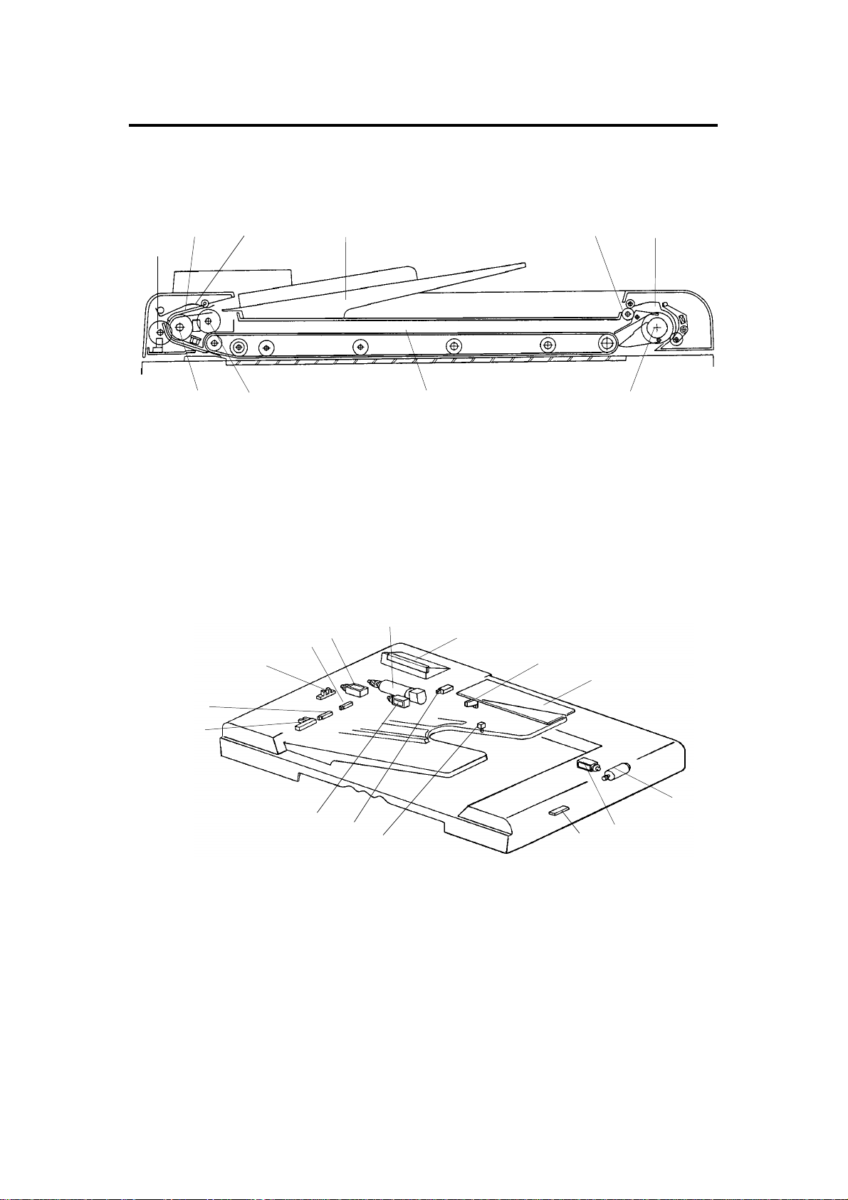
2. COMPONENT LAYOUT
– Mechanical Components –
23
1
4
6
10
1. Pulse Generator Disk 6. Inverter Pawl
2. Friction Belt 7. Inverter Roller
3. Pick-up Lever 8. Transport Belt
4. Original Table 9. Pick-up Roller
5. Exit Roller 10. Feed Roller
– Electrical Components –
2
1
9
3
4
5
14
15
13
8
6
7
8
12
7
9
10
11
1. Original Set Sensor 9. DF Main Board
2. Registration Sensor 10. Feed-out Motor
3. Pulse Generator Sensor 11. Inverter Solenoid
4. Original Width Sensor 12. Feed-out Sensor
5. Pick-up Solenoid 13. Original Select Switch
6. Belt Drive Motor 14. Feed-in Solenoid
7. Indicator Panel 15. DF Position Sensor
8. Lift Switch (A111 copier only)
2
Page 4

1 May 1993 ELECTRICAL COMPONENT DESCRIPTIONS
3. ELECTRICAL COMPONENT DESCRIPTIONS
Symbol Name Function Index No.
Motors
M1 Belt Drive Motor DC servomotor that drives to the transport belt
and feed-in system (pick-up roller, feed roller,
pull-out roller and relay roller).
M2 Feed-out Motor DC servomotor that drives the feed-out unit of
the DF.
Solenoids
SOL1 Pick-up Solenoid Energizes to press the pick-up lever against
the stack of originals in preparation for original
feed-in.
SOL2 Feed-in Solenoid Turns on to engage the feed-in clutch so
rotation is transmitted to the feed roller,
pull-out rollers, and relay rollers.
SOL3 Inverter Solenoid Energizes to invert the original when copying
two sided originals.
6
10
5
14
11
Switches
SW1 Lift Switch Informs the CPU when the DF is lifted and
also serves as the jam reset switch for the DF.
SW2 Original Select
Switch
Sensors
S1 Original Set
Sensor
S2 Registration
Sensor
S3 Original Width
Sensor
S4 Pulse Generator
Sensor
S5 Feed-out Sensor Checks for original misfeeds and sets original
S6 DF Position Sensor Detects when the document feeder is
Printed Circuit Boards
PCB1 DF Main Board Controls all DF functions. 9
PCB2 Indicator Panel
Board
Selects thick original mode or thin original
mode.
Informs copier CPU that originals have been
placed and causes the Insert Original
indicator to go out.
Sets original stop timing and measures
original length.
Determines the width of the originals. 4
Generates pulses used to measure the
original length.
stop timing when in auto reverse mode.
positioned about 10 cm above exposure
glass. (A111 copier only)
Contains operator indicators. 7
8
13
1
2
3
12
Feeder
Document
3
Page 5
OVERALL MACHINE CONTROL 1 May 1993
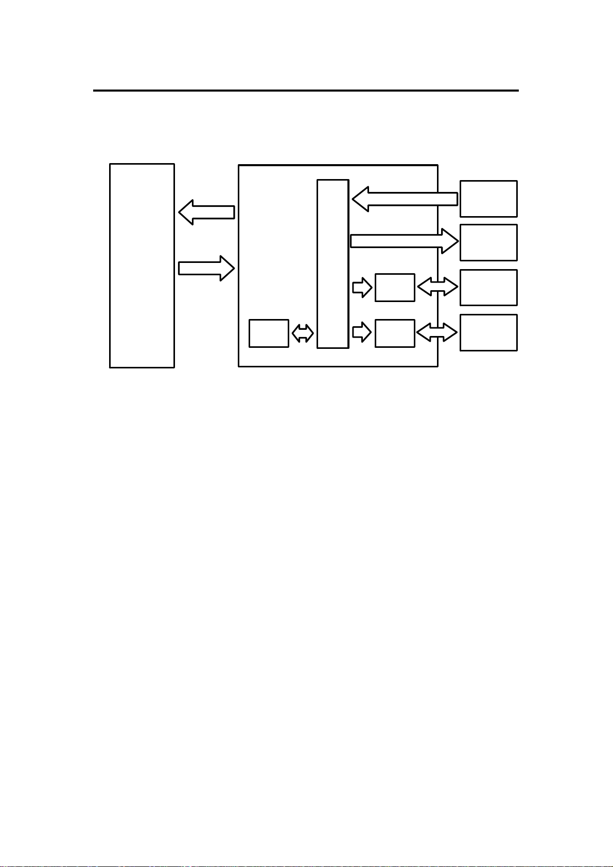
4. OVERALL MACHINE CONTROL
Copier Main Board (PCB1)
RXD
TXD
TXD
RXD
DF Main Board (PCB1)
ROM
CPU
Driver
IC
Driver
IC
Sensors
Switches
Solenoids
Indicators
Belt Drive
Motor
Feed-out
Motor
The DF CPU monitors the input signals from the sensors and switch es, and
energizes the solenoids and the indicator LEDs directly. The belt drive motor
and the inverter motor are cont rolled by the DF CPU through their respective
driver ICs. The exchanged signals are shown in the tables on the next page.
4
Page 6

1 May 1993 OVERALL MACHINE CONTROL
1. DF → Copier
No. Signal Name Definition
1 Original Set Originals are set on the original table
2 Copy Start Allows the copier to start copy sequence
3 Lift Up The DF is lifted
4 DF Misfeed Misfeed occurs in the DF
2. Copier → DF
No. Signal Name Definition
1 Feed-in Requests the DF to feed-in the original
2 Feed-out Requests the DF to feed-ou t the original
3 Invert Original Requests the DF to invert the orig ina l
4 Auto Feed Shifts the DF to the auto feed mode
5
Original Stay Atte mpt to use DF but th e original from the
previous copy run remains on th e exposure glass
Feeder
Document
5
Page 7

BASIC OPERATION 1 May 1993
5. BASIC OPERATION
1. One-sided Original Feed
When an original is inserted face up into the DF, the Inse rt Orig inal indicator
light goes out and the DF informs the copier CPU that originals have been set.
When the Start key is pressed, the copier CPU sends the feed-in signal to
the DF. On receipt of this signal, th e DF ene rgize s the pick-up solen oid, the
feed-in solenoid, and the be lt drive moto r in orde r t o feed -in th e bott om sheet
of the original stack onto the exposure glass. The pick-up solenoid and the
feed-in solenoid remain energized until the original leading edge reaches the
DF registration sensor. The belt drive mo tor t urn s off shortly after the
original’s trailing edge passes the DF registration sensor.
While feeding the original, the DF registra tio n sen sor and the paper width
sensor check the origina l size.
Just when the origina l trailing edge has passed the DF registra tio n sensor,
the DF CPU sends the copy start signal to th e copier.
When the scanner reaches the return position, the copier CPU sends the
feed-out and the feed-in signals to the DF CPU in order to exchange the
original with the next original. At this time, the scanner be gin s retu rnin g to the
home position.
When the scanner comes to th e ret urn position after scannin g th e last
original, the copier CP U only sen ds the feed-out signal in ord er to fee d-out
the last original.
6
Page 8

1 May 1993 BASIC OPERATION
2. Two-sided Original Fee d
Unlike one-sided original feed, the back side of the original must be copied
first to keep the originals and copies in the correct order.
During original feed-in, the sequence is the same as fo r one-side d feed ;
however, the DF CPU also energizes the in vert er mot or an d th e inverter
solenoid a short time af te r t he origin al trailing edge has passed the DF
registration sensor. The belt drive motor continues to feed the origin al un til
the original leading edge passe s the fee d-o ut sensor. At this point the inverter
mechanism inverts the original, in preparation for copying the back side .
Then the belt drive motor reverses and th e original is fed towards the left
scale and is aligned against the scale. The DF CP U send s the copy start
signal a short time afte r the origin al trailing edge has passed the feed-out
sensor.
When the scanner reaches the return position, the copier CPU sends the
invert original signal to the DF CPU in order to make a copy of the front side.
The original is inverted in the same way as for back side copying.
3. Semi-automatic Document Feed
If a single original is inserte d int o the original table and cop ied , the DF shifts
to the semi-automatic feed mode and lights the Auto Feed ind icat or. The
Auto Feed indicator remains on for five secon ds after the copier main motor
stops. If another origina l is inserted within that five-second pe riod , it is
automatically fed and copied.
Feeder
Document
7
Page 9
POWER DISTRIBUTION 1 May 1993
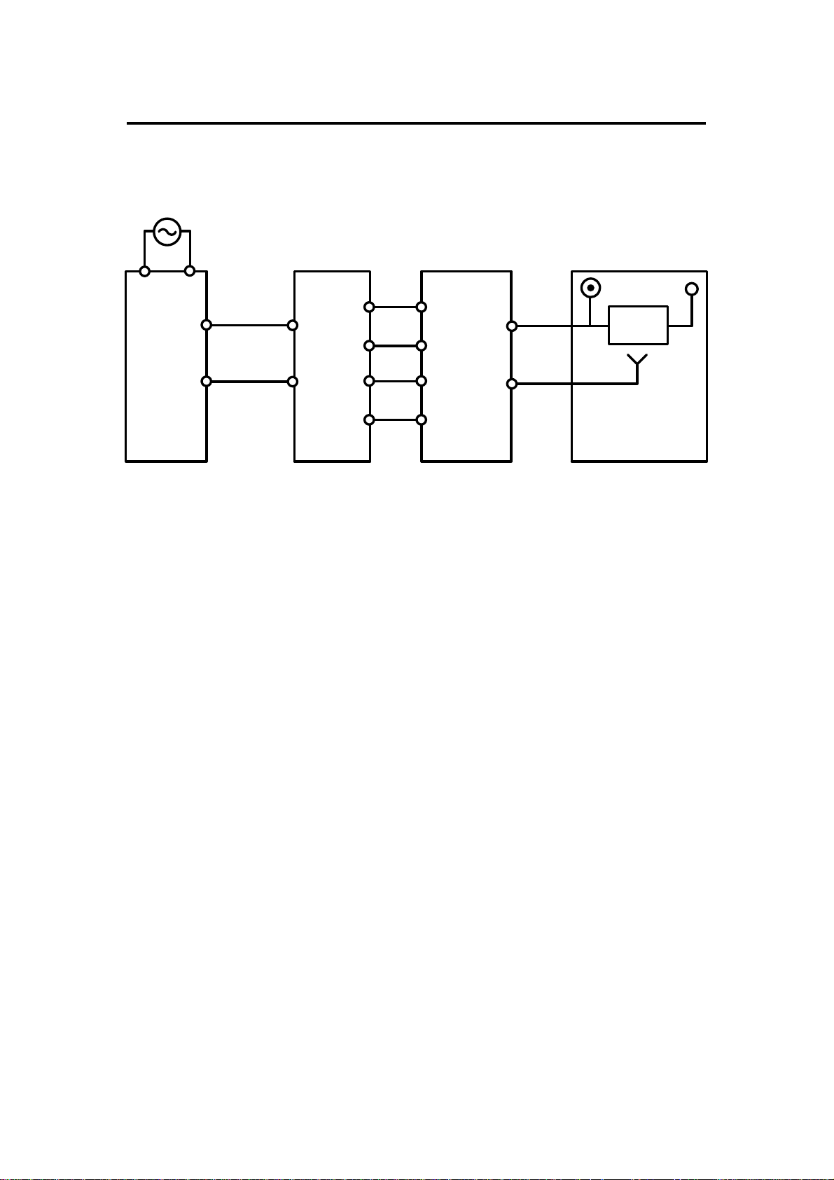
6. POWER DISTRIBUTION
6.1 A110 COPIER
+12V
Regulator
IC
5V
(PCB1)
AC Drive
Board
(PCB2)
115Vac
220/230/240Vac
Option
Transformer
(TR2)
26Vac
10Vac
Option DC
Power Supply
Board
(PCB6)
+24V
+24V (VA)
+5V (VC)
DF Main Board
The DF uses three DC power levels: +24 volts, +12 volts, and +5 volts.
When the main switch is turned on, the option transf orme r receive s the wall
outlet ac power thro ugh the ac drive board and output s 10 volt s ac and 26
volts ac to the option dc power supply boa rd. The option dc power supply
board then converts the 10 volts ac input to +5 volt s dc and the 26 volts ac
input to +24 volts. The n, tho se two dc voltages are supplied to the DF main
board.
The regulator IC on the DF main board further step s down the +24 volts to
+12 volts.
8
Page 10
1 May 1993 POWER DISTRIBUTION
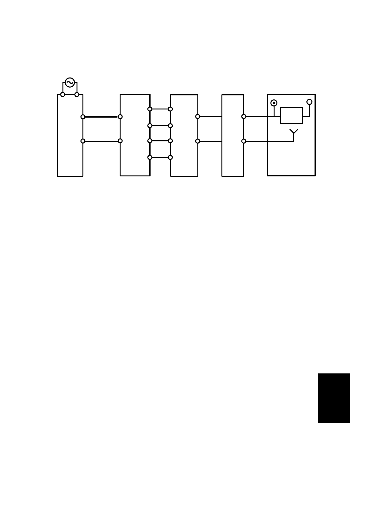
6.2 A111 COPIER
AC Drive
Board
(PCB2)
115Vac
220/230/240Vac
Main
Transformer
(TR1)
31Vac
10Vac
Main DC
Power
Supply
Board
(PCB3)
+24V (VA)
+5V (VC)
Copier
Main
Board
(PCB1)
+24V
+24V (VA)
+5V (VC)
DF Main Board
+12V
Regulator
IC
5V
(PCB1)
The DF uses three dc power levels: +24 volt s, +12 volts, and +5 volts.
When the main switch is turned on, th e main transformer receives the wall
outlet ac power thro ugh the ac drive board and output s 10 volt s ac and 31
volts ac to the main dc power supply board. The main dc power supply board
then converts the 10 volts ac inpu t to +5 volts dc an d th e 31 volts ac input to
+24 volts. Then, those two dc voltages are supplied to the DF main boa rd
through the copier main board.
The regulator IC on the DF ma in board further steps down the 24 volts to +12
volts.
Feeder
Document
9
Page 11
ORIGINAL FEED 1 May 1993
7. ORIGINAL FEED
7.1 ORIGINAL PICK-UP
[B]
[C]
[D]
[A]
After setting the origina ls on th e orig ina l tab le, the origin als con ta ct th e feeler
[A] of the original se t sen sor an d cau se the feeler to move out of th e sen sor.
The DF then sends the orig ina l set signal to the copier CPU to inform it that
the DF will be used. When the Start key is presse d, the pick-up solenoid [B]
is energized. The original sta ck is then presse d between the pick-up lever [C]
and pick-up roller [D]. The rotation of the pick-up roller advances the bo tt om
original.
[A]
10
Page 12
[B]
1 May 1993 ORIGINAL FEED
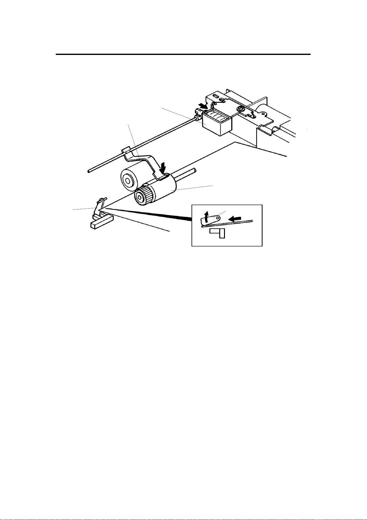
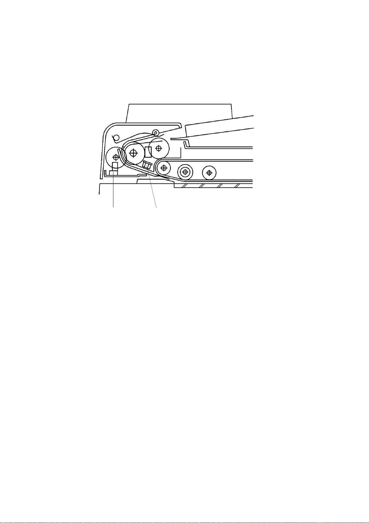
7.2 ORIGINAL SEPARATION
[A]
[B]
[C]
[A]
The feed roller [A] and the friction belt [B] are use d to fee d-in and sepa rat e
the originals [C]. Only the bottom original is fed because the friction belt
prevents any other origin als fro m f eeding.
Original feed starts when the feed roller starts turning and advances the
bottom original of the stack. The feed roller moves the original past the
friction belt because the driving force of the feed roller is great er than the
resistance of the friction belt . The friction belt prevents multiple feeds
because the resistance of the frict ion belt is great er th an the frictio n be twe en
original sheets.
Feeder
Document
11
Page 13
[E]
[D]
ORIGINAL FEED 1 May 1993
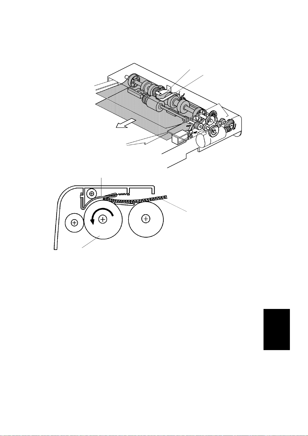
7.3 ORIGINAL FEED-IN MECHANIS M
[C]
[G]
[B]
[A]
[F]
The belt drive motor [A] drives the pick-up roller [B], the feed ro ller [C] , the
pull out roller [D], the relay roller [E], and tra nsp ort belt [F] via a feed clutch
and a gear train.
The pick-up and feed-in soleno ids are ene rgize d 10 0 milliseco nd s aft er th e
Start key of the copier is pressed. Then 100 milliseconds after the soleno ids
are energized, the belt drive motor starts turning. The pulse genera tor disc
[G] always turns when the belt drive motor is on.
Slightly after the original trailing edge passes the reg istra tio n sen sor, the
relay rollers and the transport belt sto p turnin g.
12
Page 14
1 May 1993 ORIGINAL FEED
This document feed er ha s two dif ferent ways of stopping orig inals at the
correct position on the exposu re gla ss. They are called the "thin original
mode" and the "thick original mode". The mode used is determin ed by the
original select switch [A].
[A]
– Original Select Switch –
1. Thin Original Mode
The original is stopped at th e correct position on the exposure glass ba sed
on encoder pulse count. The belt drive mot or stops shortly after the original
trailing edge passes the DF registra tio n sensor. (Exact timing depends on
registration adjustme nt.) Thin original mode is selected at the factory.
2. Thick Original Mode
When thick original mode is selecte d, the belt drive mot or rema ins en erg ized
for an additional 30 encoder pulses as comp ared to thin original mode. Then,
the belt drive motor pauses and reverse s f or 21 pulse s. This forces the
original against the left scale and thu s align s the edge of the origin al with the
scale.
After the exposu re cycle is completed, the copier send s the fee d-o ut signal to
the DF CPU and the belt drive and feed out motors start turning. At this time,
the copied original f ee ds out an d the next original feeds in.
Feeder
Document
13
Page 15
ORIGINAL FEED 1 May 1993
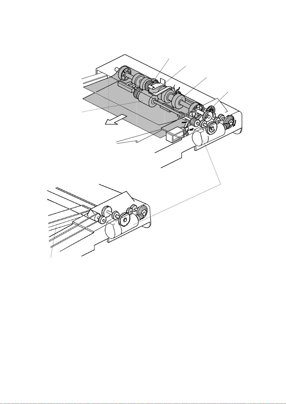
7.4 ORIGINAL SIZE DE TECTI O N
[B]
[A]
The DF determines original size (bot h widt h and len gt h) th rou gh the use of
the original width sensor [A], registration sensor, and pulse generat or sensor
[B]. The original’s length is calculated by counting the number of pulses from
the pulse generator while th e reg istration sensor is on.
Original size detection is necessary for the feed-in /feed-out timing of the DF.
14
Page 16

1 May 1993 ORIGINAL FEED
7.5 ORIGINAL INVERSION MECHANI SM
[D]
[C]
[E]
[B]
1)
[D]
[A]
The two sided originals are invert ed in the feed-out unit.
1) When the copier St art key is pre ssed , the two sided original is fed into the
feed-in unit, passing over th e DF re gist ration sensor [A]. The fee d-o ut
motor [B] and the inverter sole no id [C] turn on 100 milliseconds after the
original trailing edge passes the registratio n sen sor. When the invert er
solenoid turns on, the inverter pawls [D] rotate counterclockwise.
15
Feeder
Document
Page 17

ORIGINAL FEED 1 May 1993
2) 4)
3) 5)
6)
2) The original passes over the expo sure glass and feeds into the fee d-o ut
unit.
3) The original is directed ont o th e exposure glass again by the inve rte r
pawls. The belt drive motor now reve rses 14 0 milliseco nd s aft er th e feed
out sensor [E] turns on. The transport belt then moves the origin al to ward
the left scale. Slightly before the original reaches the left scale, the belt
drive motor drops to half spee d. This is to prevent damaging the edge of
the original against the left scale .
When the original leading edge reach es th e lef t scale , th e belt drive motor
stops. At the same time, th e feed-out motor and the inverter solenoid turn
off.
4) After the reverse side of the origin al is expo sed, the belt drive motor, the
feed-out moto r, and the inverter solenoid turn on, and the origin al is fed
into the inverter section . (This is the same as ste p 2 ab ove .)
5) The original is fed onto the exp osure glass again as in step 3 above. The
front side of the orig ina l is th en co pie d.
6) After the fron t side of th e original has been exposed, the original is fed
out from the DF.
16
Page 18

1 May 1993 ORIGINAL FEED
7.6 ORIGINAL FEED- OUT ME CHANI SM
[A]
[D]
[C]
[B]
The exit rollers [A] are driven by the inverter motor [B]. When the document
feeder receives the feed out sign al fro m t he copier, the transport belt and the
exit rollers start turning simulta neou sly. The tran spo rt belt carrie s the origin al
to the inverter rollers [C] and the exit rolle rs take over the original feed-out .
When the original trailing edge passes th e feed -ou t sensor [D], the feed-out
motor drops to half of its normal spee d for 2 20 millise con ds an d then stops.
The lower speed preven ts un eve n stacking of originals. For A3 or double
letter size originals, th e feed-out motor speed does n ot chan ge due to th e
length of the originals.
Feeder
Document
17
Page 19

ORIGINAL FEED 1 May 1993
7.7 BELT DRIVE MOTOR CIRCUIT
DF Main Board (PCB 1)
CPU
Speed
Data
ON/OFF
Forward/
Reverse
Driver
IC
PWM
Driver
Circuit
+5V
Phase A
Phase B
CN102-1
CN102-2
CN103-1
CN103-2
CN103-3
CN103-4
Belt Drive
Motor
Encoder
A dc servomotor is used as the belt drive motor. The driver IC contro ls the
speed of the belt drive motor. The CPU sen ds th e speed dat a (programmed)
to the driver IC. The driver IC sends the pulse-width-mod ula tio n (PWM)
signal to the driver circuit, which sen ds the motor drive pulses.
An encoder in the servomot or ha s two magnetic sensors that genera te two
pulse signals (phase A and B). The drive r I C monitors the belt speed and
direction by these pulse sign als an d use s t his data to regulate the moto r’s
speed.
18
Page 20

1 May 1993 ORIGINAL FEED
7.8 FEED-OUT MOTOR CIRCUI T
DF Main Board (PCB 1)
CN104-A2
FG
CPU
High/Low
ON/OFF
Driver
IC
AC Feedback
Voltage
Regulation
Motor
Drive
Circuit
CN104-A15
CN104-B8
CN104-A12
Feed-out
Motor
The DF CPU sends the speed data (high or low) t o th e drive r IC a nd the
motor drive circuit. The moto r drive circuit creates the PWM signal and sends
the motor drive pulses to the feed-out motor.
The frequency genera to r o f th e feed-out motor makes a very low voltage ac
current which is fed back to the driver IC. The driver IC monito rs the
frequency of this ac current and based on the frequency it reg ulates the
motor speed.
19
Feeder
Document
Page 21

ORIGINAL FEED 1 May 1993
7.9 INPUT AND OUTPUT CIRCUITS
Original Set Sensor
P
S
CN104-B1
CN104-B9
CN104-B15
DF Main Board (PCB1)
+5V
[ 12]
[ 12]
CN104-A10
CN104-A17
Lift SW (SW1)
Pulse Generator Sensor
P
S
Registration Sensor
P
S
Original Width Sensor
P
S
Feed-out Sensor
P
S
Original Select SW
P: Photoreceiver
S: Schmitt Trigger Circuit
Feed Out
Motor
CN104-B2
CN104-A9
CN104-B17
CN104-B11
CN104-B16
CN104-A11
CN104-A1
CN104-B10
CN104-A16
CN104-A5
CN104-B8
CN104-A12
+5V
[0-12]
[ 5]
[ 5]
+5V
[ 5]
[ 5]
[ 0 0/24]
GND
CPU
Forward
[ 0 0/24]
Return
[ 0 0/24]
+24V
[ 24]
+24V
[ 24]
+24V
[ 20]
[ 19]
[ 20]
CN104-B6
CN104-A3
CN104-A6
CN104-B14
CN104-B5
CN104-A13
Insert Original
CN104-B12
Auto Feed
CN104-A4
Misfeed
CN102-1
CN102-2
Pick-up
SOL
Inverter
SOL
Indicator Panel
Belt Drive
Motor
The above devices are directly con tro lled and monit ored by the CPU. The
solenoids and indica to r p anel are energized with +24 volts. The sensors and
switches are energized with +12 volts or +5 volts.
To energize a solenoid or in dica tor, the CPU drops the conne cte d trigger line
from +24 volts to LOW. The CPU monitors t he inpu t line s of th e sen sors and
switch to determine when they are activa te d.
20
Page 22

[B]
1 May 1993 LIFT MECHANISM
8. LIFT MECHANISM
[A]
[C]
[D]
[G]
[A]
[F]
[E]
When the document feeder is ope ne d, the lift springs [D] provide enough
force to ensure that the document feeder does not fall onto the exposure
glass. When the document fe eder is clo sed , po int s "A" , "B", and "C" are
aligned and no such force is provided to the document feed er.
[B]
[C]
The lift switch [E] is actuated when the docu men t fe ed er is closed . The copier
then shifts to the document feeder mode. The lift switch also serves as th e
reset switch for document fe ed er misfe ed s.
When a book or thick (maximum thickness 60 mm) original is copied, the DF
acts as a cover for the original a s shown in the figu re [F] . The lift switch is
turned off during th is cond ition, so the DF does not function. The tension of
spring [G] returns th e DF t o th e no rmal con dition after copying a thick orig ina l.
21
Feeder
Document
Page 23

ORIGINAL MISFEED SENSING 1 May 1993
9. ORIGINAL MISFEED SENSING
The registration sensor and the fe ed-out sensor are used for misfeed checks.
1. One sided original
Registration Sensor
ON check (685 ms)
Feed-out Sensor
Belt Drive Motor
OFF check (1250 ms)
ON check (1250 ms)
OFF check (1250 ms)
Feed-out Motor
If the registration sensor is not actu at ed wit hin 685 millise con ds af te r the belt
drive motor starts turning, the Origin al Misfe ed indicator lights (ON check).
If the registration sensor does no t tu rn of f with in 1, 25 0 milliseco nds, th e CPU
determines that there has been an original misfeed (O FF check). The
Original Misfeed indicato r also ligh ts if the feed-out sensor is not actu at ed
within 1,250 milliseconds after the feed-out motor starts turning (ON check)
or if the feed-out sensor does not turn off within 1,250 milliseconds after the
feed-out sensor is actuate d (OFF che ck).
22
Page 24

1 May 1993 ORIGINAL MISFEED SENSING
2. Two sided original
Registration
Sensor (RS)
RS ON check (685 ms)
Feed-out
Sensor (FS)
Inverter Solenoid
RS OFF check (1250 ms)
100 ms
FS OFF check (1250 ms)
FS ON check (1250 ms)
Belt Drive Motor
Feed-out Motor
Forward
Reverse
The registration ON/OFF check is the same as for one-sided originals. Th e
inverter motor and the inve rte r solen oid turn on 100 milliseconds after the
registration senso r t urn s off. If the feed-out sensor is not actuated within
1,250 milliseconds after the feed-out motor starts turning, the Original
Misfeed indicator lights (ON check). The Origin al Misfeed indicator also lights
if the feed-out sensor does not turn off within 1,250 milliseconds after the belt
drive motor reverses (OFF check).
If a previous original remains on the expo sure glass af ter manual copying
and DF feed is attempted, the original misfeed indicat or ligh ts. When the DF
is lifted and the previous original is removed, DF copying is permitted.
23
Feeder
Document
Page 25

[2]
[9]
[10]
[17]
INSTALLATION PROCEDURE (for Machine Code: A110/A111) 1 May 1993
10. INSTALLATION PROCEDURE
(for Machine Code: A110/A111)
10.1 ACCESSORY CHECK
Check the accessories and their q uant itie s according to the following list:
1. Original Table............................ .. .................... .. .......... .. ..................1 pc
2. DF Mounting Bracke t (fo r A 027/A048/A054/A075 /A 11 0/ A1 11 )......1 pc
3. Angle Stopper..................................................................................1 pc
4. Lift Switch Actuator..........................................................................1 pc
5. E Plate................................... .. .......... .. .................... .. .......... .. ..........1 pc
6. Spacer - 0.5 mm.......................... .. .......... .. .................... .. .......... .. ....6 pcs
7. Spacer - 0.2 mm.......................... .. .......... .. .................... .. .......... .. ....4 pcs
8. DF Harness Bracket (for A0 27 /A048/A054/A075/A030/A072)........1 pc
9. Bushing (for A027/A048/A054/A075/A030)..................................... 1 pc
10. Toothed Wash er.............. .......... .. .......... .. .................... .. .......... .. ......1 pc
11. Ground Screw - M4 x 6...................... .. .... .. .. .. .. .. .. .... .. .. .. .. .. .. .... .. .. .. ..1 pc
12. Hexagon Head Screw - M4 x 10 .....................................................4 pcs
13. Philips Screw with Flat Wash er - M4 x 5................. .. ............ ..........4 pcs
14. Philips Pan Head Screw - M4 x 5 (round head).............. .. .. .. .... .. .. ..3 pcs
15. Philips Pan Head Screw - M4 x 5 (flat head)................... .. .. ............2 pcs
16. Philips Pan Head Screw - M3 x 5....................................................1 pc
17. Philips Pan Head Screw with Washe r - M3 x 5 (for A054/A111) ....1 pcs
18. Stud Screw............................ .. .. .... .. .. .. .. .. .. .... .. .. .. .. .. .. .... .. .. .. .. .. .. .... ..2 pcs
19. DF Test Sheet ....... .. .......... .. .................... .. .......... .. .................... .. ....1 pc
[1]
[3]
[4] [5] [6] [7] [8]
[11] [12] [13] [14] [15] [16]
[19]
[18]
24
Page 26

[22]
1 May 1993 INSTALLATION PROCEDURE (for Machine Code: A110/A111)
[20]
[21]
[23] [24]
[25] [26] [27]
20. Philips Pan Head Screw - M5 x 10 (for A030/A072).......................2 pcs
21. DF Mounting Bracket (for A030/A072).......... ............ ............ ..........1 pc
22. DF Bracket (for A0 30 /A 07 2).................................... .. .................... ..1 pc
23. Sensor Actuato r (for A054/A111)........................................ .. ..........1 pc
24. Sensor Actuator (for A072 )..............................................................1 pc
25. Philips Pan Head Screw - M5 x 12 (for A072)................. .. ............ ..2 pcs
26. Clamp (for A072/A110/A111) ..........................................................1 pc
27. Philips Pan Head Screw with Flat Washer - M4 x 8
(for A072/A110/A111)......................................................................1 pc
(for Machine Code: A0 27 /A 04 8/ A075/A110)
When the DF is installed, the power supply unit (option) is required. Make
sure that you have all th e acce ssories listed in the power supply unit
installation procedure.
25
Feeder
Document
Page 27

INSTALLATION PROCEDURE (for Machine Code: A110/A111) 1 May 1993
[A]
"X" "Y"
"Z"
NOTE: 1. Connector (3P/Brown ) [ A] on the DC harness assembly is not
used on the A027, A030, A048, A075 and A11 0 Copiers.
2. The clamp position of th e DF harness with the bushing or clamp is
different for each mach ine as follo ws:
"X" position ..... A027 copier
"Y" position ..... A030, A048, A054, A072 and A075 copiers
"Z" position ..... A110 and A111 cop iers
26
Page 28

1 May 1993 INSTALLATION PROCEDURE (for Machine Code: A110/A111)
10.2 INSTALLATION PROCEDURE
[E]
[A]
[B]
[C]
[F]
[I]
[H]
[D]
[G]
1. Install the power supply unit (A110 copier only) .
Refer to the installa tion procedure enclosed wit h th e po wer sup ply un it
(A525).
2. Remove the following parts from the copier.
1) Platen cover [A] (2 push-locks)
2) Platen cover pedestal [B] (4 screws)
3) 2 screws [C] for fixing the operation panel
4) Rear cover [D] (4 screws)
3. Cut the two links [E] with nippers and bend the large harness cap [F] in
until it touches the rear cover.
4. Remove the lift sensor [G] (1 screw) (A111 copier onl y) .
5. Remove the CC/G/B power pack [H] (1 screw and 2 locking supports)
and clamp the connector [I] as shown in the illu stra tio n; the n rein sta ll the
CC/G/B power pack (A111 copier only).
Feeder
Document
27
Page 29

INSTALLATION PROCEDURE (for Machine Code: A110/A111) 1 May 1993
[A]
[C]
[C]
"a"
[B]
[D]
6. Secure the DF mounting bracket [A] (4 screws [12 ]).
7. Adjust the height of the DF mounting bracket in the following order:
1) Set the E plate [B] on the expo sure glass as shown and measure the
clearance "a" between the DF mounting bracket and E plate using a
scale.
2) Remove the DF mounting bracket and insert the spacers [C] in orde r
that the clearance "a" is between 0 mm and 0.3 mm.
8. Remove the strip of tape [D].
28
Page 30

[B]
1 May 1993 INSTALLATION PROCEDURE (for Machine Code: A110/A111)
[C]
[A]
9. Mount the DF on the DF mounting bracket aligning the holes in the DF
and the pins on the mountin g bra cket, then slide the DF to the lef t as
shown.
10. Secure the DF to the DF mountin g bracket (4 screws [13]).
11. Secure the 2 stud screws [A] as shown in the fig ure .
12. Install the lift switch actuator [B] (1 screw [16]).
13. Install the sensor actuator [C] [23] (1 screw [ 17] ) (A111 copier onl y) .
Feeder
Document
29
Page 31

[L]
INSTALLATION PROCEDURE (for Machine Code: A110/A111) 1 May 1993
[A]
[C]
[B]
[A110 copier]
[A111 copier]
[J]
[E]
[I]
[D]
[I]
[K]
[F]
[G]
[L]
[D]
[H]
14. Set the clamp [A] between the last two binders [B] of the DF harness [C]
as shown (1 screw [27]).
15. Connect the optics fiber cable connector (2P/Black) [D] to CN13 3 on the
main board [E].
[E]
16. Connect the dc harness conne cto r (4 P/ Whit e) [F] to the optional harness
connector [G] equip pe d with the power supply unit (A110 copier only).
17. Connect the dc harness conne cto r (4 P/ Whit e) [H] to CN134 on the main
board (A111 copier only) .
18. Disconnect the connector [I] (3P/Brown) f rom th e platen cover position
sensor connector [J], then connect the connector [I] to the connector [K]
of the DF harness (A11 1 copi er onl y) .
19. Secure the groun din g wire [L] (1 screw and toothed washer).
30
Page 32

1 May 1993 INSTALLATION PROCEDURE (for Machine Code: A110/A111)
[B]
[A110 copier]
[C]
[A]
[E]
[D]
20. Connect the harness conne cto r [ A] to CN102 on the dc power su pply u nit
(A110 copier only).
21. Clamp the optiona l harness [B] as shown (A110 copier only).
22. Remove the DF main PCB cover [C] and tu rn off DIP switch 101-2.
NOTE: Make sure that DIP switch 101 -1 is on an d th e other switches
(101-2, 3 and 4) are off.
23. Install the angle stopper [D] (2 screws [15]).
24. Install the original table [E].
Feeder
Document
31
Page 33

INSTALLATION PROCEDURE (for Machine Code: A110/A111) 1 May 1993
[A]
[C]
[B]
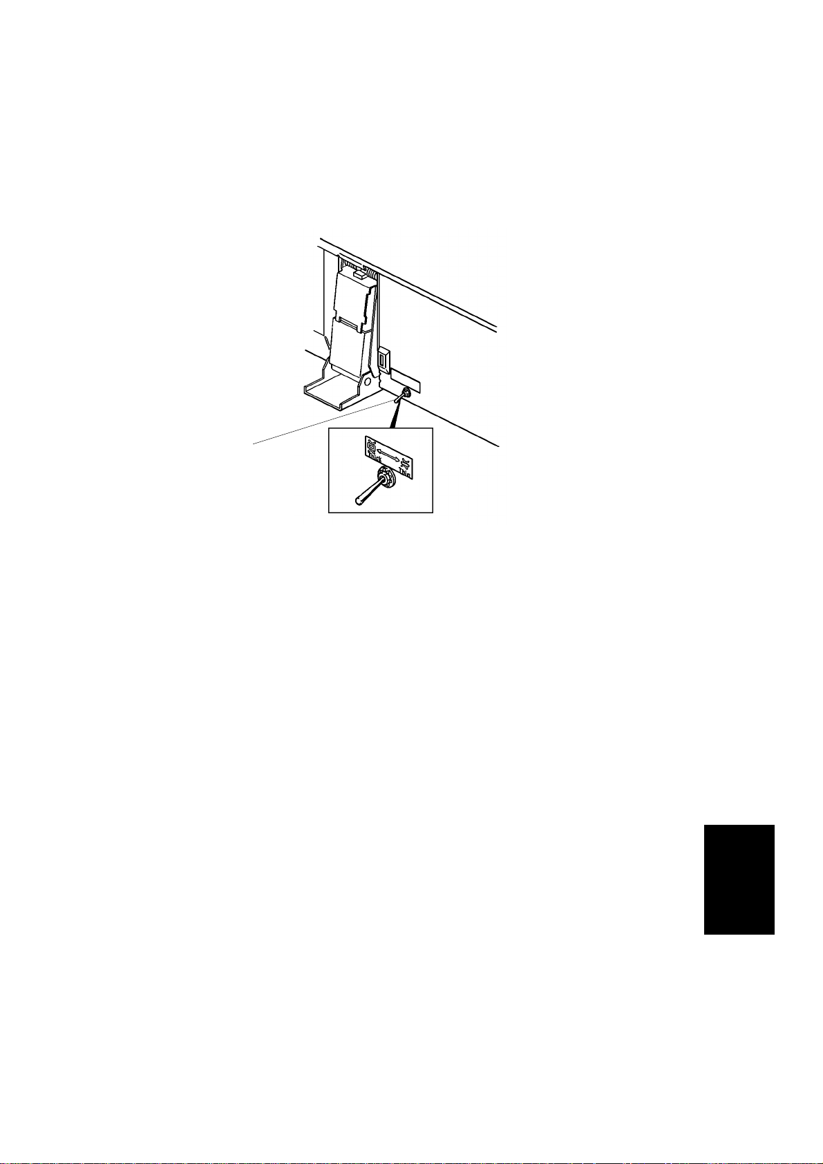
25. Adjust the height of the magnet catch es in th e fo llowin g ord er:
1) Remove the grip cover [A] (3 screws)
2) Loosen the screws of the magnet catches [B] (2 screws each)
3) Close the document fee de r and tighten the screws of the magnet
catches when the rubber stopper [C] contacts the exposure glass.
26. Reinstall the grip cover (3 screws).
NOTE: Open and close the docume nt fee de r co nf irming that the magnet
catches are making good contact.
27. Plug in the copier and turn on the main switch.
28. Confirm the original registration. (See page 33.)
29. Reassemble the copier. (The DF harne ss f its in th e cut -out on the rear
cover as shown.)
30. Check the operatio n of the DF.
31. Position the original sele ct switch to th in pape r mode (normal position)
and explain the funct ion of this switch to the customer.
32
Page 34

1 May 1993 INSTALLATION PROCEDURE (for Machine Code: A110/A111)
[A]
Original Registrati on Adjustm ent
1. Make a copy of the test sheet in the platen mode (A 4 widt h).
2. Confirm that the original select switch is in the thin original mode and
make a copy in DF mode (A4 width).
3. Compare the registration of the copy in platen mode with that of the DF
mode, and confirm that the difference is within 2.5 mm.
4. If the difference is more than 2.5 mm, remove the DF main PCB cove r [A]
(1 screw) and adjust VR102 to change the origina l-sto p timing.
NOTE: Turning VR102 clockwise results in the original sto pping later.
5. Make a copy of the test sheet in DF two-sided original mode.
NOTE: a) The test sheet should stop presse d ag ain st the left scale in DF
two-sided original mode.
b) The position of the original select swit ch does no t mat te r .
6. Compare the registration of the copy in platen mode with that of DF
two-sided original mode, and confirm that the dif ference is within 2.0 mm.
7. If the difference is more than 2.0 mm, remove the DF main PCB cover
and adjust VR103 to change the orig ina l-sto p timin g.
NOTE: a) The test sheet should stop presse d ag ain st the left scale in DF
two-sided original mode.
b) Turning VR103 clockwise results in the original sto pp ing later.
Feeder
Document
33
Page 35

[A]
[B]
PREPARATION FOR TRANSPORTATION 1 May 1993
11. PREPARATION FOR TRANSPORTATION
CAUTION: Before moving the document feeder, be sure to prepare it
for transportation as follows. The document fee der may be
badly damaged if it is moved without proper prepa ra tion.
[B]
1. Remove the original table [A].
2. Secure the document feeder with strips of ta pe [B] as sh own in the
illustration.
34
Page 36

1 May 1993 REPLACEMENT AND ADJUSTMENT
12. REPLACEMENT AND ADJUSTMENT
12.1 FEED-IN UNIT
12.1.1 Transport Belt Replacement
[C]
[A]
[D]
[B]
1. Turn off the main switch and remove the grip [A] (3 screws).
2. Remove the DF main PCB cover [B] (1 screw, 1 connector).
3. Open the entrance guide [C] and remove the tran sport belt assembly [D]
(5 screws).
Feeder
Document
35
Page 37

REPLACEMENT AND ADJUSTMENT 1 May 1993
[C]
[B]
[A]
4. Remove the 2 tension springs [A] and pull off the transport belt [B].
NOTE: a) When installing the tra nsport belt, make sure the belt lies
between the belt guide spacers [C].
b) When installing the tra nsport belt assembly, make sure th e
positioning pin correctly fits in the DF frame, and hold open the
exit guide to prevent the mylar strip from be comin g damaged.
36
Page 38

1 May 1993 REPLACEMENT AND ADJUSTMENT
12.1.2 Feed-in Unit Removal
[B]
[A]
1. Turn off the main switch.
2. Remove the transport belt assembly. (See Transport Belt Replacement.)
3. Remove the belt drive motor cover [A] (4 screws).
4. Remove the feed-in unit [B] (4 screws, 8 connectors).
Feeder
Document
37
Page 39

REPLACEMENT AND ADJUSTMENT 1 May 1993
12.1.3 Pick-up Roller Replacement
[A]
[B]
[C]
[D]
1. Turn off the main switch.
2. Remove the feed-in unit. (See Feed-in Unit Removal. )
3. Remove the lower entrance guide [A] (2 screws).
4. Remove the original set sensor assembly [B] (1 screw, 1 connector).
5. Remove the pick-up roller [C] (3 E-rings, 1 bushing, 1 gear).
NOTE: a) Be careful not to loose the pin [D].
b) When installing the roller, make sure the positioning pin is
correctly inserted in the cut-out of the roller.
c) When installing the gear, make sure th e fla t side of the gear is
facing away from the roller.
38
Page 40

1 May 1993 REPLACEMENT AND ADJUSTMENT
12.1.4 Feed-in Clutch Lubrication
[B]
[D]
[C]
[A]
1. Turn off the main switch.
2. Remove the original set sensor assembly. (See Pick-up Roller
Replacement.)
3. Remove the feed-in solenoid lever spring [A].
4. Remove the pick-up roller assembly [B] (2 E-rings, 2 bushings).
5. Disassemble and lubricate the feed clutch [C] (1 E-ring) with Mobil Temp.
78.
NOTE: a) Be careful not to loose the pin [D].
b) When installing the fe ed clutch, make sure the positionin g pin is
correctly inserted in the cut-out of the clutch.
Feeder
Document
39
Page 41

REPLACEMENT AND ADJUSTMENT 1 May 1993
12.1.5 Pick-up Solenoid Adjustment
[C]
[D]
[B]
[F]
[E]
[A]
1. Turn off the main switch.
2. Place several sheets of paper [A] over the expo sure glass area.
3. Lower the feed-in unit (see Fee d-in Unit Removal) without disconnecting
the eight connecto rs.
4. Turn on the main switch.
NOTE: When the main switch is turned on, the DPS1 01 setting on the
DF main PCB must be as follows:
1 = ON 3 = OFF
2 = ON 4 = OFF
This is so that the initial check sequence can take place.
40
Page 42

1 May 1993 REPLACEMENT AND ADJUSTMENT
5. Turn off DPS101-1 and 2, then turn on DPS101-3 and 4 [B].
6. Loosen the screw fixing the pick-up solenoid [C].
7. Place the 0.15 mm thickness gauge [D] between th e plunger and the
solenoid.
8 While holding the solenoid , press SW101 [E] on the DF main PCB to
engage all DF solenoids.
9. Holding the solenoid securely, move it slowly towards the left, until the
plunger is attracted to the solenoid. Just at th is point, tighten the screw.
NOTE: Make sure the pick-up lever is touch ing the pick-up roller during
this adjustment.
10. Press SW 102 [F] to turn of f th e solenoids.
11. Turn off DPS101-3 and 4, then turn on DPS101-1 and 2.
12. Turn off the main switch and reassemble the DF.
13. Check the original feed-in operation.
41
Feeder
Document
Page 43

REPLACEMENT AND ADJUSTMENT 1 May 1993
12.1.6 Feed Roller Replacement
[C]
[A]
[B]
1. Turn off the main switch.
2. Remove the lower entrance guide. (See Pick-up Roller Replacement.)
3. Loosen the front bracket [A] (2 screws).
4. Release the feed roller shaft [B] from the front bracket (1 E-ring, 1
bearing).
5. Remove the feed roller [C] (3 E-rings, 1 side roller, 1 pull-out roller).
NOTE: a) Take care not to lose the pin s.
b) When installing the fe ed roller, make sure the gear side of the
roller faces the front (see illustration).
c) When installing the side and pull-ou t rolle rs, make sure the pins
are correctly inserted in the cut -ou ts of the rollers.
42
Page 44

[D]
1 May 1993 REPLACEMENT AND ADJUSTMENT
12.1.7 Feed-in Solenoid Adjustment
[B]
[C]
[A]
1. Turn off the main switch.
2. Place several sheets of paper [A] over the expo sure glass area.
3. Lower the feed-in unit (see Fee d-in Unit Removal) without disconnecting
the eight connecto rs.
4. Check that DPS101 is set for the normal mode (1 = ON, 2 = ON, 3 =
OFF, 4 = OFF).
5. Turn on the main switch.
6. Turn off DPS101-1 and 2, then turn on DPS101-3 and 4 [B].
7. Loosen the 2 screws securing the feed-in solenoid [C].
8. Press SW101 on the DF main PCB (to engage all DF solenoids) and
adjust the position of the solen oid until the gap [D] (see illustration) is
within 1.0 – 2.0 mm.
9. Press SW102 on the DF main PCB to turn off all DF solenoids.
10. Turn off DPS101-3 and 4, then turn on DPS101-1 and 2.
Feeder
Document
43
Page 45

REPLACEMENT AND ADJUSTMENT 1 May 1993
12.1.8 Friction Belt Replacement
[A]
[B]
[C]
[D]
1. Turn off the main switch.
2. Remove the seal cover [A] on top of the DF cover.
3. Remove the friction belt assembly [B] (1 screw).
4. Remove the friction belt [C] (2 springs, 1 pin).
NOTE: a) When installing the friction belt assembly, make sure the
friction roller [D] is set in the corre ct position (see illustration).
b) If the seal cover becomes dirty or def orme d, replace it with a
new one.
44
Page 46

[A]
1 May 1993 REPLACEMENT AND ADJUSTMENT
12.2 FEED-OUT UNIT
12.2.1 Feed-out Unit Removal
[C]
[B]
1. Turn off the main switch.
2. Remove the DF grip [A] (3 screws).
3. Remove the feed-out motor cover [B] (4 screws).
4. Remove the feed-out unit [C] (4 screws, 3 connectors).
Feeder
Document
45
Page 47

REPLACEMENT AND ADJUSTMENT 1 May 1993
12.2.2 Inverter Solenoid Adjustment
[A]
[B]
[C]
[D]
1. Turn off the main switch.
2. Place several sheets of paper [A] over the expo sure glass area.
3. Lower the feed-out unit (See Feed-out Unit Removal) without
disconnecting the th ree connectors.
4. Check that the DPS101 is set for the normal mode (1 = ON, 2 = ON, 3 =
OFF, 4 = OFF).
5. Turn on the main switch.
6. Turn off DPS101-1 and 2, then turn on DPS101-3 and 4 [B].
7. Loosen the screw securing the inverter solenoid [C].
8. Press SW101 on the DF main PCB (to engage all DF solenoids), and
adjust the position of the solenoid until the gap [D] (Se e illustrat ion) is
within 1.5 ± 0.5 mm.
9. Press SW102 on the DF main PCB to turn off all DF solenoids.
10. Turn off DPS101-3 and 4, then turn on DPS101-1 and 2.
46
Page 48

1 May 1993 REPLACEMENT AND ADJUSTMENT
12.2.3 DF Leading Edge Registration Adjustment
[A]
1. Using the DF test chart, make a copy in the platen cover mode (A4 width).
2. Confirm that the original select switch [A] is in the thin mode and again
using the test chart, make a copy in the DF mode (A4 width).
3. Compare the leading edge registration of both copies, and check tha t the
difference betwee n the two copies is within 2.5 mm.
4. If the difference is more than 2.5 mm, remove the DF main PCB cove r (1
screw) and adjust VR102 on the DF main PCB until the leading edge
registration is within specifica tio n.
NOTE: Turning VR102 clockwise results in stoppin g the origina l la ter.
5. Using the DF test chart, make a copy in the DF two sided-o rigin al mode.
(Insert the origina l face down.)
6. Compare the leading edge registration with that of the platen cover mode
copy, and check that the diff erence between the two copies is within 2.00
mm.
7. If out of specification, adjust VR103 on the DF main PCB until the
leading edge registration is correct.
NOTE: a) The test sheet stops pressed against the left scale in DF
two-sided original mode.
b) Turning VR103 clockwise results in the original sto pp ing later.
Feeder
Document
47
Page 49

Normal
Setting
[B]
REPLACEMENT AND ADJUSTMENT 1 May 1993
12.3 BELT DRIVE MOTOR SPEED ADJUSTMENT
[A]
[C]
NOTE: The belt drive speed adjustment is require d whe n th e main board is
replaced.
1. Turn off the main switch.
2. Check that DIP switch 101 is set for the normal setting as follows:
101-1 101-2 101-3 101-4
ON OFF OFF OFF
3. Turn on the main switch and DIP switch 101-2 and -4.
4. While turning on the lift switch manually, adjust the belt drive motor speed
using VR101 [A] so that both the Insert Origin al ind icator [B] and Auto
Feed indicator [C] tu rn off.
NOTE: a) When the Insert Original indicator ligh ts, turn VR10 1 clockwise
to reduce the motor speed.
b) When the Auto Feed indica tor lights, turn VR101
counterclockwise to increase the motor speed.
c) Confirm that both indicators remain off for approximately 5
seconds in order to stabilize the mot or spe ed .
5. Turn off DIP switch 101-2 and -4.
NOTE: Do not use VR106. This variab le reg ister is for adjusting feed-out
motor speed. This is preset by th e ven do r.
48
 Loading...