

Page 1
Page 2
Page 3
SEP
30
-
'R7
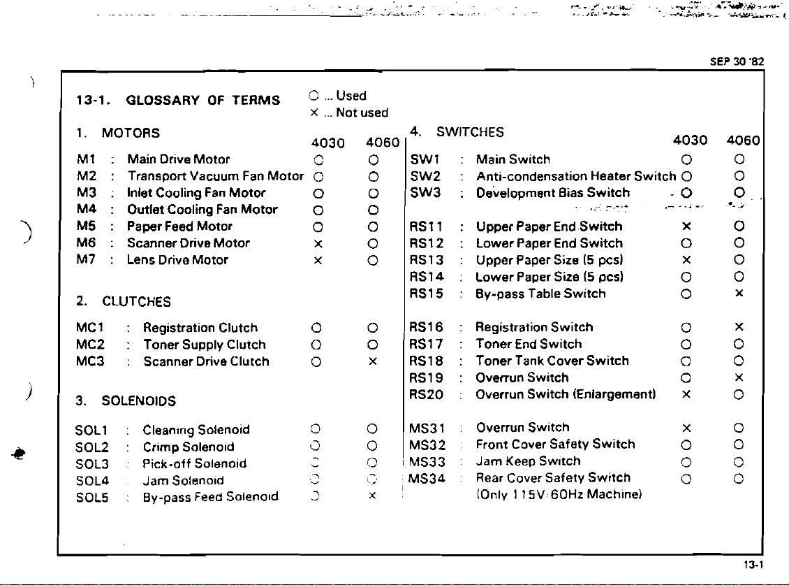
13-1.
1. MOTORS
M1 : Main Drive Motor
M2 : Transport Vacuum Fan Motor
M3 : Inlet Cooling Fan Motor
M4 : Outlet Cooling Fan Motor
M5 : Paper Feed Motor
M6 : Scanner Drive Motor
M7 : Lens Drive Motor
2. CLUTCHES
MCl
MC2
MC3
3.
SOL1
SOL2
SOL3
SOL4 Jam Solenold
SOL5
GLOSSARY
:
Registration Clutch
:
Toner Supply Clutch
:
Scanner Drive Clutch
SOLENOIDS
:
Clean~ng Solenoid
:
Crimp Solenold
:
Pick-off Solenoid
:
By-pass Feed Solenold
OF
TERMS
...Used
X
...
Not used
4030 4060
0
C
0
0
0
X
x
0
0
0
0
a
-
.+
,
-
3
0
0
0
0
0
0
0
0
0
x
0
0
O
$3
x
4. SWITCHES
SW1
SW2
SW3
RSl 1
RS12
RS13
RS14 : Lower Paper Size
RS15
RS16
RS17
RS18
RS19
RS20 : Overrun Switch (Enlargement)
MS31 : Overrun Switch
MS32 . Front Cover Safety Switch
MS33 : Jam KeepSw~tch
I
MS34 : Rear Cover Safety Switch
:
Main Switch
:
Anti-condensation Heater Switch
:
De'velopment Bias Switch
:
Upper Paper Endswitch
:
Lower Paper End Switch
:
Upper Paper Size (5 pcs)
:
By-pass Table Switch
:
Registration Switch
:
TonerEndSwitch
:
Toner Tank Cover Switch
:
Overrun Switch
IOnly 1 15V60Hz Mach~ne)
.
._
(5
_,..I
pcs)
4030
0
0
-
0
,-
-
..
x
0
x
0
0
0
0
0
0
X
x
0
0
0
-,
Page 4
iEP
30
'82
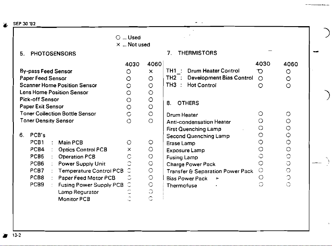
5.
PHOTOSENSORS
0
...
X
...
Used
Not used
-.
7. THERMISTORS
-
By-pass Feed Sensor
Paper Feed Sensor
Scanner Home Position Sensor
Lens Home Position Sensor
Pick-off Sensor
Paper Exit Sensor
Toner Collection Bottle Sensor
Toner Density Sensor
6.
PCB's
PCB1
PCB4 : Optics Control PCB
PCB5
PCB6
PCB7
PCB8
PCB9
:
MainPCB
:
Operation PCB
:
Power Supply Unit
:
Temperature Control PCB
:
Paper Feed Motor PCB
:
Fusing Power Supply PCB
Lamp Regurator
Monitor PCB
4030 4060
0
0
0
0
0
0
C
0
0
x
C
-
-
C
Z
'3
-
-
.-
x
0
0
0
O
0
0
0
0
0
0
0
0
'5
0
-
~'
-,
-'
THl-: Drum Heater Control
TH2 : Development Bias Control
TH3 : Hot Control
8. OTHERS
Drum Heater
Anti-condensation Heater
First Quenching Lamp
Second Quenching Lamp
Erase Lamp
Exposure Lamp
Fusing Lamp
Charge Power Pack
Transfer & Separation Power Pack
1
Bias Power Pack
i
Thermofuse
I
I
*
4030 4060
'0
0
0
0
0 0
0
0
0 0
0
3
0
0
0
3
0
0
0
0
0
0
0
0
,3
0
n
1
G
Page 5

SEP
30
'0
13-2.
CN
CONNECTOR
Anti-condensation Heater Switch (SW-2)
1
2 Exposure Lamp
3 Anti-condensation Heater
4 Lamp Regurator (AC)
5 Outlet Cooling Fan Motor (M4)
6
Transformer
8 Connect to CN9
9
Connect to CN8
10 Lamp Cooling Fan Motor (M3)
1
1
Drum Heater
12 2nd Quenching Lamp
13 Main Motor (MI
14
Fusing Unit
15 Connect to CN78
16 Power Supply Unit
17
Transport Vacuum Fan Motor (M2)
18 SADF AC Power
21
Erase Lamp
22 Power Supply Unit
23 Power Supply Unit
Scanner Home
3 1
32 Lens Home Pos~t~on Sensor
33 Lens Drrve Motor (M7)
34 Scanner Drive Motor 1M6)
35 Scanner Dr~ve Motor 1M61
LIST
-
P.P.
Pos~tion Sensor
4030 4060
0
0
3
0
0
0
0
0
0
0
0 0
0
0
0
0
0
0
0
0
0
0
0
0
0
0
0 0
0
Cl
0
0
0 0
C
-,
,
-
L'
-
X
X
X
x
0
0
k3
7
.-
-
,,
.
s,
?
-
Z
...
Used
X
...
Not used
--
-
Page 6

iEP
30
'82
CN 36 Scanner Drive Clutch (MC3)
37 Overrun Swich-Enlarge
38 Registration Switch (RS16)
39 By-Pass Feed Sensor
40
Overrun Switch (MS191
41 Paper Feed Board
42 Upper Paper Size Switch (RS131
43 Upper Paper End Switch IRS1 1)
44
Lower Paper Size Switch (RS14)
45 Lower Paper End Switch (RS12)
46 Registration Clutch (MCl
47 Paper Feed Sensor
48 Crimp Solenoid (Sol. 21
49 By-Pass Table Switch (RS15)
50 By-Pass Feed Solenoid (Sol.
5
1 Toner End Switch (RS171
52 Toner Supply Clutch (MC2)
53 Toner Density Sensor
54 'Toner Tank Cover Switch (RSl81
6
1
Charge P.P.
62 Transfer & Separat~on P.P.
63 Bias P.P.
71 Pick-Off Solenoid (Sol. 31
72 Cleaning Soieno~d (Sol.
73 Interface Board
74
Pulse
Generator
78 Connect to CN15
34
(RS20l
I
5)
1
I
4030 4060
0
x
0
0
0
0
x
x
0
x
0
x
x
x
0
0
0
0
0 0
0
0
0
0
0
0
0
2
0
,-
.-
-
-
,.
2
-
"
-
-
P
"
*
"
_?
0
0
0
x
x
0
G
C
0
U
fi
L
,-
C:
r.
-
-
b
C
-
i
C
0
x
...
...
Used
Not used
Page 7

~3
L
L
L
L
L
1
6
6
18
28
~8
~8
ss
16
LO
ZO
ED
vo
SO
90
LO*
zov
EOV
LOB
zag
COB
LOL
ZOL
108
208
LO6
Z06
E06
L L
EL
uer
u!ew
u!ew
u!e~
U!~W
s~!tdo
~aiuno3 lei01
pleog uolierado
~aluno3 Aax
raiuno3 uo!ido
(v
'10s)
P!OU~IOS
(3a)
~oie~n6an duel
PJEO~
PJeoa u!ew
PJ~OR
PJ~OE
PJ~OE
pleog wen
pJeog loriuo3 s31ido
pleog 1oriuo3 sslido
PJeOfl
(OJlU03
preog uo!te~ado
preog uo!ie~ado
p~eog uo!ierado
PJ~
paaj Jaded
PJeOB Paaj Jaded
p~eog a3egaiu1
peon asegaiul
pleog lo~)uo3 a~nle~adwal
pJeOg lortuo3 a~nie~adual
pleog Alddns JaMOd 6u!snj
pleog Alddns JaMOd 6u!snj
p~eog Alddns JaMOd 6u!snj
:8.
OC
d3S
pasn
...
0
pasn
to^
.-.
x
.
.
8
-
--,,.
?..
<
.::!>;,i,.
.
,
0
0
0
0
o
"0.
o
0
o
0900
.~
~
OEOV
0
0
0
0
o
0
o
0
'
o
0 0
0
0
x
x
X
0
0
0
0
0
0
0
0
0 0
x
0 0
0 0
0
2
3
0
0
C
0
0 0
ir
-
C
0
0
b
-
Page 8

13-3.
FAULT INDICATOR CHECK
LET
INDICATOR
POSSIBLE CAUSE
SERVICE CALL INDICATOR: When the
Service Call Indicator lights, one of the
following
the right of such indicator is the electrical components which can cause this
condition.
INDICATOR
Optics
LED'S will light up. -Listed to
POSSIBLE CAUSE
-~
~
-~~
~
1) CN91-3 or CN91-2 level is
OV
during waiting condition.
#
Shorted L.R.
(Photocoupler is defective)
#
Main Boiard defective
(CN103-86.B91
21
Shorted L.R.
(1 0 sec. timer is defective)
31 lnterference from other P.C.B.
Boards.
1 1 Overrun
reduction)
sw.
(full size or
is
shorted
(immediately response).
21 Overrun
opened (Enlarge mode
sw.
(enlarge) is
settlng
is completed, then check)
Optics
Functional
Drive
3) Lens home position
ICN321
is opened - Check 4.5 sec.
after main sw. ON
4)
Power supply un* 24V line
has no output.
5)
Scanner home position (CN31
is open or shorted.
6)
lnterference from other P.C.
Boards.
1
I
Photocoupler
2) CN74
CN103-018
31
41 Main Board
51 Main Motor
61
CN13-1. CN16-4
71 CN13-2
81 Motor Trigger Srgnal
CN22-10, CN102-B6
91 CN22-3. CN23-1- - 24V line
101 RA1 contacts
1
11
RAl
coil
12) CNl0-2A7. -1
3
131 CN78-5. CN91-5. CN91-4
141 Interference from other PC.
Boards
I
I
136
Page 9

1
INDICATOR POSSIBLE CAUSE
-
Drum Heater Thermistor Open
(TI411
1) Erase lamp unlt - CN21 -A.
open
2)
Drum thermistor ITHI open
3)
Thermistor
Failure
No Indication
CN701-5,
41 No. 7 P.C. Board shorted
51
CN701-6. CN103-89
61 Main Board defective
7) Interference from other P.C.
Boards
-
Fusing Thermistor Failure - lTH3l
8) TH1 is shorted or opened.
9) CN78-1.2
10) Same as 4). 6).
1) Total Counter
#
Defective
#
Between CN8 1-4 and
CN81-3 stays ON
#
Between CN81-4 and
CN8 1-3 stays ON
2)
Interference from other P C.
Boards.
-8
open
-
B
I
#
"Other PC. Board'' mean display board.
SADF. Sorter.
Please take out connector respectively.
Then replace
Opt~cs.
defectwe P
C.
Board
Page 10

C,
SEP
XI
'82
POWER SUPPLY
I
I
~77
VPP
"CC
VEE
VMM
VK
I
1
f
Status
+
Vpp (CN23-6)
UNIT
LEVEL
+IOV
+24V
+
5.1V
-
5V
+15V
-25V +AC32V
Level means no load condition.
is
different from other circuits.
TABLE
I
+11.5V
+Z.5V
+
-
+27.5V
1
+24.8V CN23-1 White
1
-25.7V
5.15V
5.1V
I
~~22-8
CN235
CN22-1
CN22-2
CN23-3
.
CN22-3
1
CN22-6
I
I
Orange
Blue
Red
Sky
Blue
Yellow
White
Gray
I
1
..
Page 11

,
12
11
10
951
When
me
fuses
the machine becomes the condition as shown below.
4
8
3
7
2
6
in the power supply unit are cut off,
91
6
3 Power supply unlt
81
5
2 T4060lFT4030
714 1
/
SEP
JO
'8
-
,
LL1
0
E
,
In
$
C
LL
FUSE
FS601 (5A)
FS602 (0.5A)
FS603 (5A)
FS604 (5A)
RS605
15AI
1
Fuse
1
i
Fuse
2
Fuse
3
PHENOMENON
No
Responce. Machine Stays OFF
Responce, Machine Stays OFF
No
Scanner
Service Call "OPTICS"
Abnormal Indications
No Output for Power Pack
1
No Response, Mach~ne Stays OFF
!
No Output to Power Packs
I
No Response. Machine Stays OFF
Drive Motor doesn't work
CONNECTOR
All No. Output
All No. Output
--
CN23.3
CN22.3, CN23.1
CN23-5
All No Outout
CN 16.8
All No Output
 Loading...