

Page 1
Page 2
-
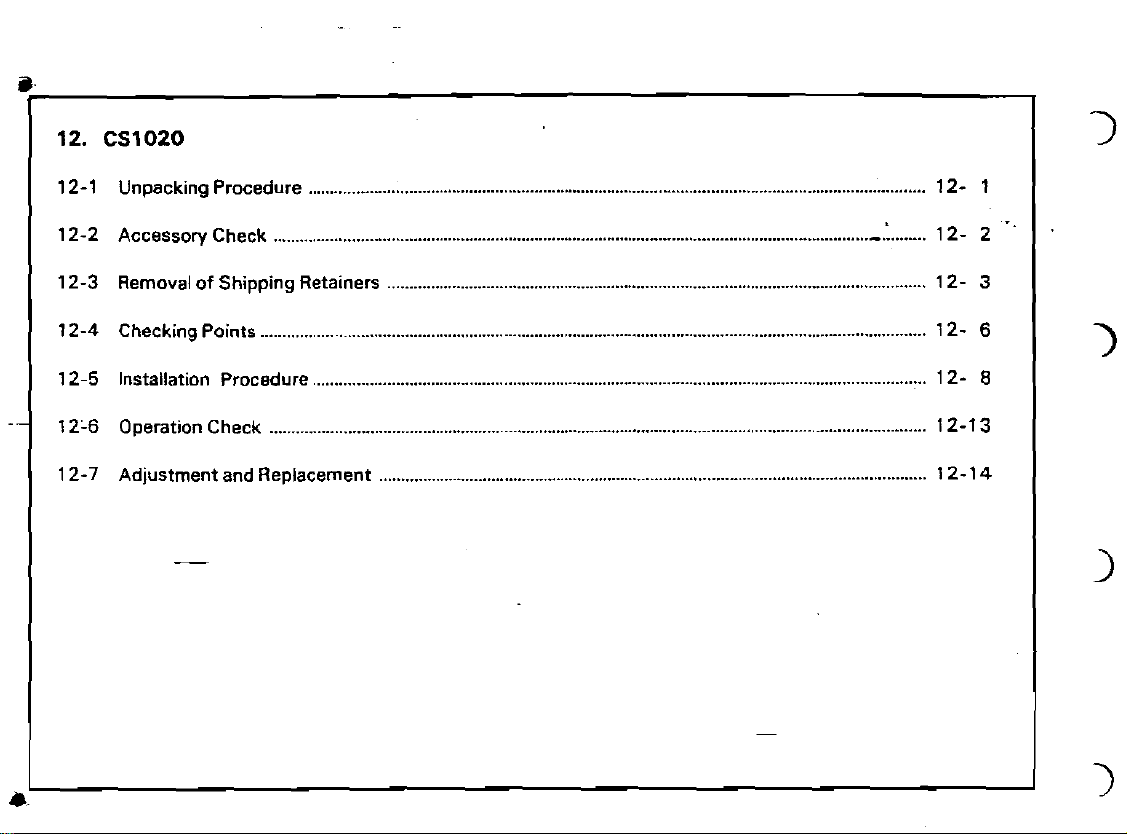
12 . CS1020
-
12-1 Unpacking Procedure
12-2 Accessory Check
12-3 Removal of Shipping Retainers
12-4 Checking Points 12-
12-5 Installation Procedure
123 Operation Check
1
2-7 Adjustment and Replacement
............................................................................................................................................
.....................................................................................................................................
............................................................................................................................
.............................................................................................................................................
............................................................................................................................
:
.....
12- 1
12- 2
12-
12-
12-1
12-1
3
6
8
3
4
Page 3
I
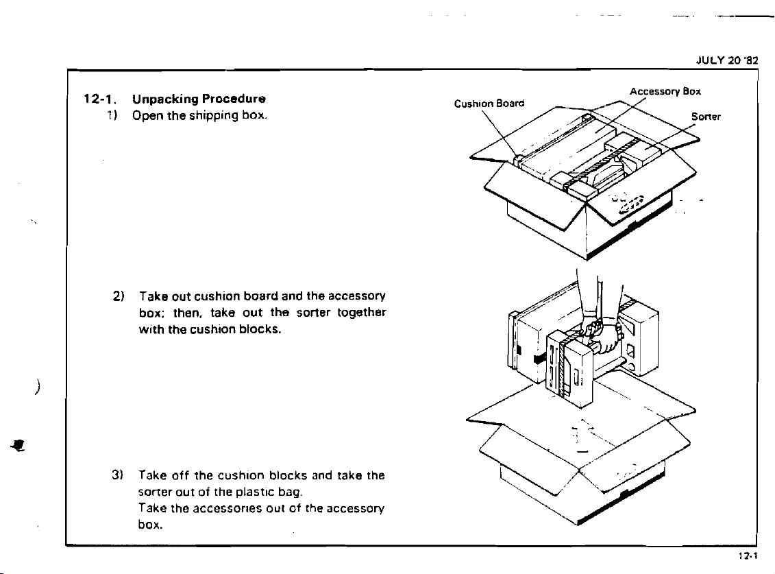
12-1.
1)
Unpacking Procedure
Open the shipping box.
Take out cushion board and the accessory
2)
box: then. take out the sorter together
with the cushion blocks.
Cushnon
Board
Accemrow
BOX
JULY
20 '82
I
i
3)
Take
off
the cushlon blocks and take the
sorter
out of the plastlc bag.
Take the
box.
accessories
out
of
the accessov
Page 4

SEP
I
30
'82
12-2.
Accessory Check
Check
quantlty and condition of the accessories according to the New Equipment Condition Report or the following list.
-.
1) New Equipment Condition Report
2)
Studs for Connection
3)
Knob Screw
41 Signal Cable
5) 12P Harness
61
10 Standard Bins and 1 Interrupt Bin
71 Orig~nal Receiver
8)
Philips Screw w~th Flat Washer
91 Envelope for NECK
101 Installation Procedure
1 11 Connector Holder
121 Pan Head Screw
...................................................
........................
.................................................
.................................
..
....................
I1
15V only)
........................................
M4
x
6
...........................
.........
...
..............
.............
Page 5
JULY
20 '82
-
4
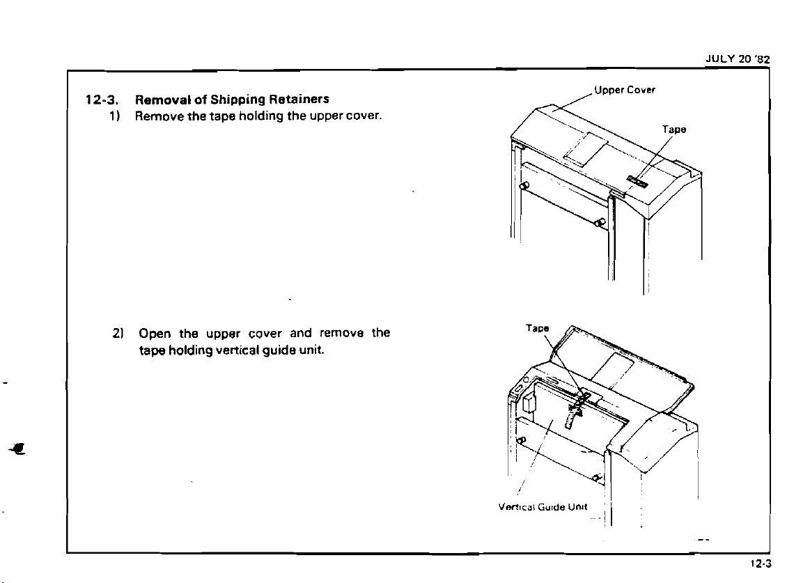
12-3.
Removal
Remove the tape holding the upper cover.
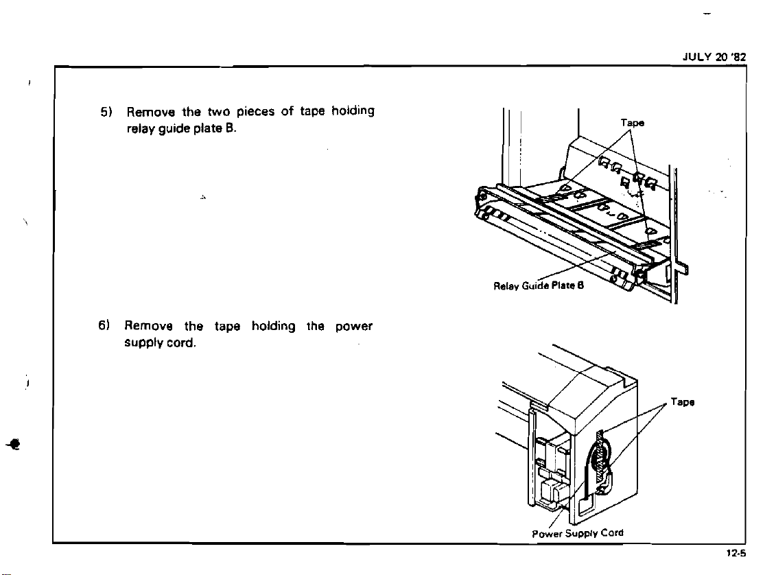
11
Open the upper cover and remove the
21
tape holding vertical guide unit.
of
Shipping Retainers
VBR~CQI
Gutde
Unar
I
-/I
;
-.
12-3
Page 6
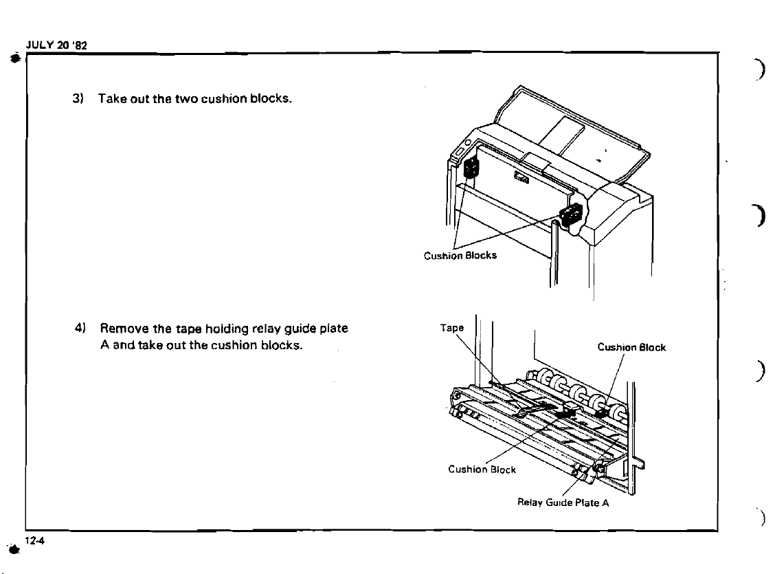
41
Remove the tape holding relay guide plate
A
andtake
out the cushion blocks.
Page 7
Page 8
SEP
30
'82
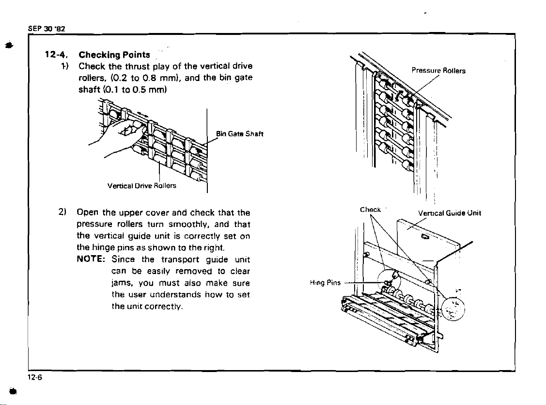
12-4.
21
Checking
Check the thrust play of the vertical drive
1)
rollers.
(0.2
Points
to
0.8
,
'
mm),
and the bin gate
Open the upper cover and check that the
pressure rollers turn smoothly. and that
the vertical guide unit is correctly set on
the hinge pins as shown to the right.
NOTE:
Since the transport guide unit
can be easily removed to clear
jams, you must also make sure
the user understands how to set
the unit correctly.
in
Gata
Shafi
Hlng
Pins
leal
Guide
Unit
12-6
Page 9

3)
Visually check that the bin gates do not
protrude into the paper path.
(Gap
A
must be 1 to
Check that the bin gates pivot smoothly.
4)
1.5
mm)
Page 10

12-5.
2)
Installation Procedure
1)
Remove the four plastic caps from the
docking holes.
NOTE:
Screw in the lower mounting studs.
If the
machine, remove the original receiving tray and reinstall two
screws.
OF10
is mounted on the
Page 11

4)
Remove the cover plate from the connector
bracket.
5)
a).Bend down C156, C157, and RAY108
on the copier main PCB as shown to the
left.
b).Connect the 18P adapt harness to
CN402 o the interface PCB.
c).lnstall the interface PCB to CN106 on the
copier main PCB.
d). Bind the 18P adapt harness to the harness
from CN103 with a nylon fastener.
e).Mount the connector for the signal cable
onthe connector bracket as shown to the
left.
Note:
-
Sorter
6) Take off the upper cover and the front cover
of the
Triangle mark on both the
connector and the connector
lock plate should be pos~tioned
upward.
-
sorter.
.
2
screws
3
screws
2
screws
Cover Plats Conmtor
lnterfacd PCB
IBP
Adapt
Canneclo<
Harness
Lock
"
Plate
.:
SEP
3
'82
racket
Cop!er
Ma~n
PCB
'-..
Nvlon Fastener
12-9
Page 12
JULY
20
'82
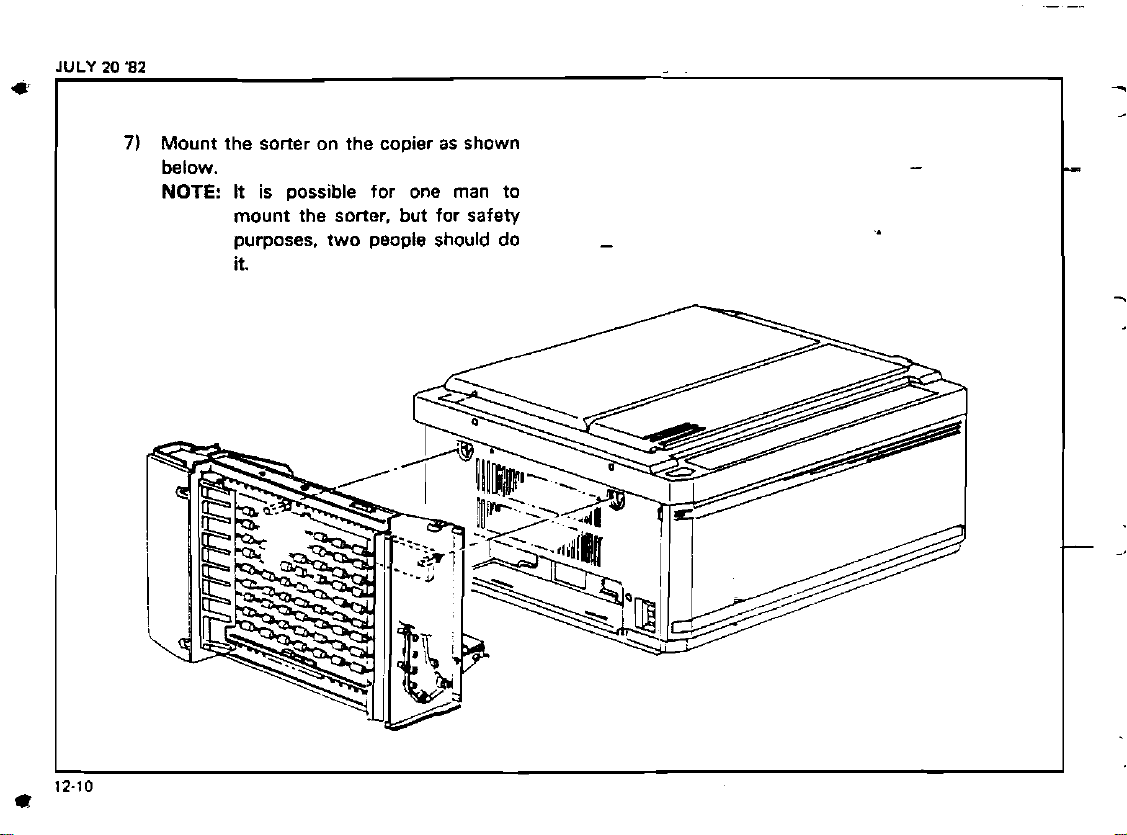
71
Mount the sorter on the copier as shown
below.
NOTE:
It is possible for one man to
mount the sorter, but for safety
purposes, two people should do
it.
-.
-
>
Page 13
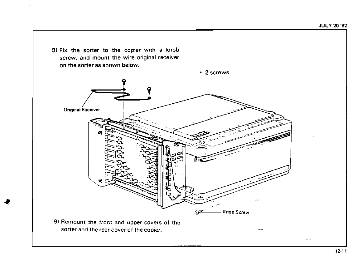
81
Fix
the sorter to the copier with a knob
screw, and mount the wire original receiver
on the sorter as shown below.
-
2
screws
JULY M '82
91
Remount the front and upper covers of the
Sorter and the rear cover of the copier.
Knob
Sctsw
Page 14

SEP
J)
'82
10)
After confirming that the main switch is
off, connect the signal cable between the
copier and sorter, and plug in the sorter
and install the connector holder.
11)
Set the bins from bottom to top starting
with the interrupt bin. Make sure each bin
is fully set as shown to the right.
NOTE:
The standard bin without untistatic brush should be mounted
in the 10th bin position.
Stanaard
Bins
0th
>
1
Bin
Page 15

SEP
30
82
12-6.
2)
3)
4)
5)
6)
7)
8)
Operation Check
Tum on the main switch.
1
)
Press the sort and stack keys and check
that the each indicator turns on correctly.
Insert a sheet of paper into the first bin.
Press the sort key. The print key should
change from green to red.
Then take out the sheet. The print key
should change back to green.
Repeat steps 3 and 4 using the stack key.
Open
the sorter cover. The check sonar
indicator
i
<
)
should light.
Press the son key and then enter 11
copies. The print key should change from
green to red.
Press the stack key and enter 41 copies.
The print key should change from green
to red.
CAUTION: Do not remove the
cable without first turning off
main switch.
s~gnal
.,:;
-
-,*.
.
*,
.
.
..
. .
-
?
d
.
~
12-13
Page 16

1
12-7.
Adjustment and Replacement
-
Bin Copy Sensor Adjustment
1.
Operate the copier in free run mode (DIP
SW100
minutes. (To allow
up.)
2. Confirm that there
3.
Check the voltage of the sensor signal by
connecting the hot line of the tester to
the rear side of
to CN212-2
Adjustment Standard:
(LED1 05: OFF)
4.
Adjust with VR2.
5. Place a sheet of translucent paper in a bin.
6.
Check thevoltage.
Adjustment Standard: Less than
(LED1 05: ON)
NOTE:
#l.
-
on the main PCB) for three
the sensors to warm
is
no paper in bins.
"R2", and the neutral line
(red. ground).
+
7.5 to + 8.OV
+
2.OV
LED105 w~ll light when the
sensor
than +5.95V.
s~onal voltaoe
-
-
IS
less
Jam
Sensor
Bin
CO&
I
Signal
Sensor
Signal
GND
(Redl
CNZ12
I
Page 17

I
-
Jam Sensor Adjustment
1. Operate the copler in free run mode (DIP
SwlOO
minutes.
up.)
Confirm that three is no paper in bins and
2.
between the vertical drive rollers.
Check the voltage of the sensor signal by
3.
connecting the hot line of the tester to
the rear side of
to
CN212-2 Ired. ground).
Adjustment Standard:
(LED1 04: OFF)
4. Adjust with VRl.
Place a sheet of translucent paper in a bin.
5.
6.
Check the voltage.
Adjustment Standard: Less than
(LED1 04: ON)
NOTE: LED104 will light when the
-
#l.
on the main PCB) for three
(To allow the sensors to warm
"Rl", and the neutral line
+
7.5
to + 8.OV
+
2.OV
sensor signal voltage is less
than
+5.95V.
1
11
SEP
30
'82
Page 18
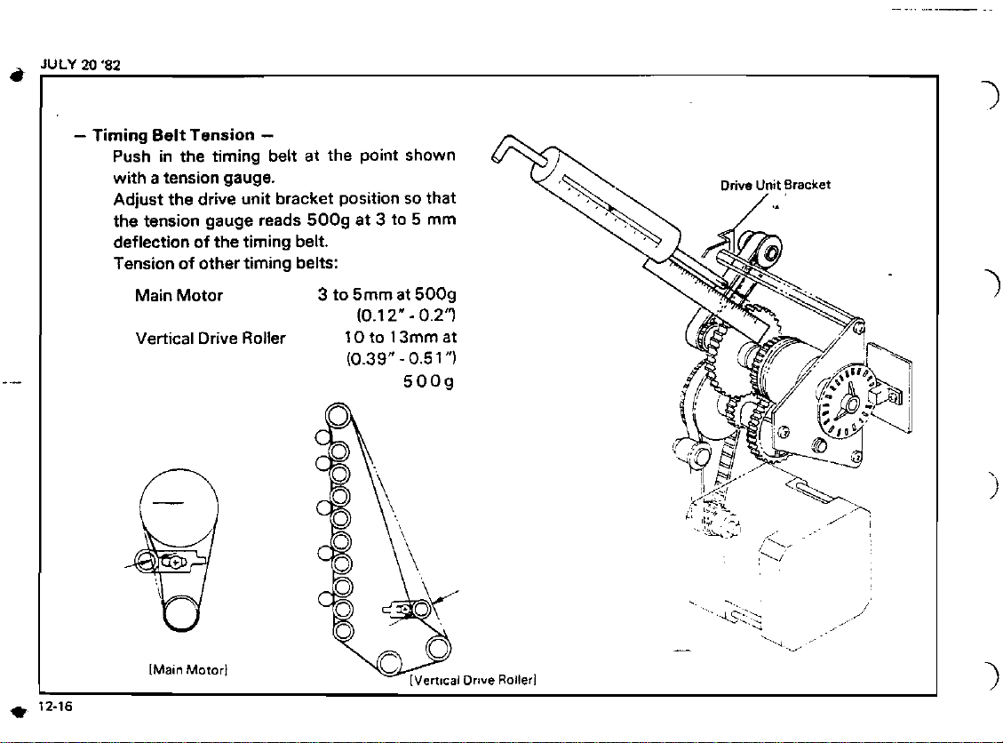
-
Timing Belt Tension
Push in the timing belt at the point shown
with a tension gauge.
Adjust the drive unit bracket position so that
the tension gauge reads
deflection of the timing belt.
Tension of other timing belts:
Main Motor
Vertical Drive Roller 10to 13mmat
IMam
Motor1
-
5009 at 3 to 5 mm
3
to 5mm
(0.39"
(0.1
at
5009
2"
-
-
0.5
5009
0.2'7
1")
..
...
....
.L~::\
..
.
v
-
.
_.
.,
/
Page 19

.
.
,
,
-
Gate Solenoid Replacement
1)
Take off the top cover and rear cover.
21 Disconnect all connectors from the
sorter CPU board.
3)
Remove the CPU board together with
its bracket
'4)
Loosen the three screws securing the
solenoid bracket.
5)
Unhook the solenoid spring.
6)
Replace the solenoid and reassemble
the sorter.
NOTE:
1.
Check the thrust play of the
bin gate shaft
mml.
2.
Check that the bin gates
pivot smoothly.
/:I
-
'I
(0.1
to
.I
0.5
SEP
30
'82
,.
4
screws
2
screws
Page 20

JULY
20
i
1
'82
-
Sponge Roller Replacement
1)
Remove all bins and take the sorter
off of the copier.
2) ~ake off the rear sorter
cover and remove the trans-
former.
3)
Lay the sorter on its side.
4) Remove the upper 4 screws and
loosen the lower
the lower relay guide plate.
5)
Draw the outline of the belt
bracket on the side plate. (This is to
make readjustment easier duringreassembly.)
61
Remove the belt tightener bracket.
7)
Remove the sponge roller drive pulley
and bearing from the front end of the
shaft, and remove the bushing from
the rear end
81
Replace the sponge roller shait.
of
-
2
screws holding
the shaft.
4
screws
2 screws
3
connectors
tightener
*
1
screw
-
1
E-ring each end
-.
Lower
Relay
Guide
Plate
-
I
7
I
Belt
Tightener
,
Bracket
Page 21

I
-
Speed-up Clutch Replacement
I
I
Take off the top cover and rear cover.
2)
Draw the outline of the drive unit
bracket on the side plate.
31
Loosen the three screws securing the
drive unit bracket, and take off the
wire clamp bracket.
41
Uncouple the drive motor, speed-up
clutch, and pulse generator connectors.
Lift off the drive unit.
51
61
Remove the pulse generator
and perforated disk.
-
PCB
-3
screws and 4 screws
-
1
screw
1
allen screw
JULY 20 '82
I
.-
Page 22

I
-
Reassembly Notes
7)
Take off the two E-rings and bearings
shown. (Don't lose the small bearings)
8)
Remove the three screws holding the
stay plate and take off the
clutch together with the shaft and
plate.
9)
Take off the belt pulley
and the large
10)
Remove the collar
and stay plate.
11
Take off the inside collar.
12)
Install
assemblv.
(The replacement part consists of the
clutch, shaft. and high speed gear.)
geai.-
a
new speed-up clutch
speed up
'
1
1
.
1
and
-
-
1)
Make sure to mount the stay plate
with the pulse counter mount pointing
outward.
2)
The large (low speed) gear must be
mounted with the one way clutch
facing inward.
31
Mount the perforated disk with the
Allen screw side in, and tighten the
Allen screw on the flat surface of the
shaft.
allen screw
E-ring
ailen screw
2
screws
1
E-ring, 1 allen screvr
4)
Do not tlghten the Allen screw of the
timing belt pulley until after
ing the shaft bearings.
reinstall-
2.20
Page 23

-
Cover Safety Switch Replacement
1)
Take off the top cover and rear cover.
2)
Take off the switch bracket.
31
Remove the four wire clamps from
the safety switch harness.
41
Uncouple the five connectors.
51
Cut off the five wire binders holding
the harness, and replace the safety
switch assembly.
-
-
3
screw and 4 screws
2
screws
-
4
screws
JULY
20
'82
NOTE:
When mounting the new switch
harness. make sure the wire
clamps are oriented as shown in
the figure to the right. If they are
mounted in the other direction.
the upper cover cannot be
mounted.
12-21
 Loading...