

Page 1
SECTION
11
Page 2
11.
DF-10
1.
Unpacking
2.
Installation Procedure
3.
Feed Belt Removal
4.
Lift Switch Adjustment
....................................................................................................................
...................................................................................................................................
-
...........................................................................................................................................................
..................................................................................................................................................
::
................
-
'11-1
1
1-2
1 1-8
1
1-9
Page 3
I
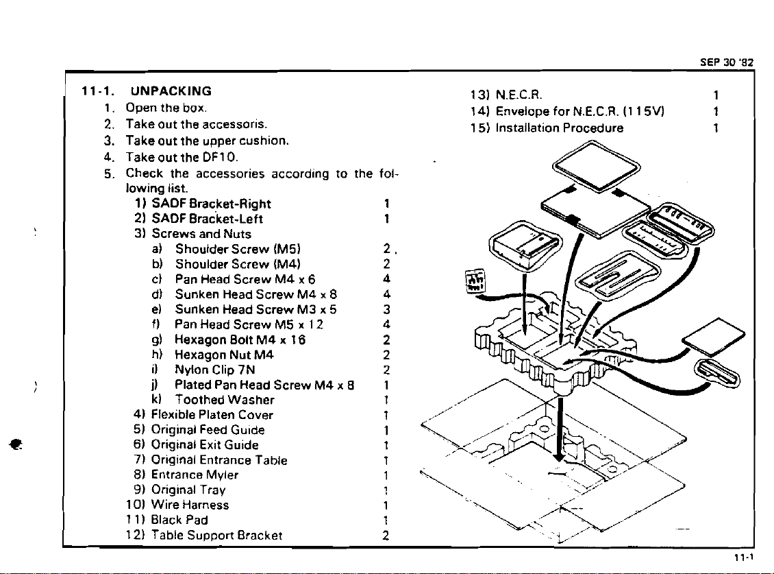
UNPACKING
Open the box.
Take out the accessoris.
Take out the upper cushion.
Take out the
Check the accessories according to the fol-
lowing list.
1)
2)
3)
4) Flexible Platen Cover 1
5) Original Feed Guide 1
6)
71 Original Entrance Table
8)
9)
1
Ol
1
1) Black Pad
I
121 Table Suooort Bracket
DF10.
SADF
Bracket-Right
SADF
Bracket-Left 1
Screws and Nuts
a) Shoulderscrew (M5)
b) Shoulder Screw (M4) 2
C)
Pan Head Screw M4
d) Sunken Head Screw M4
e) Sunken Head Screw M3 x 5 3
f)
Pan Head Screw M5 x 12 4
gl Hexagon Bolt
h) Hexagon Nut M4
il
Nylon Clip 7N
I)
Plated Pan Head Screw M4
k)
Toothed Washer
Original Exit Guide 1
Entrance Myler
Original Tray
Wire Harness
M4
x
6
x
8
x 16 2
x
4
4
2
2
8
1
2.
1
1
1
1
1
SEP
13) N.E.C.R. 1
14) Envelope for N.E.C.R.
15) Installation Procedure
(1
15V) 1
1
30
'82
I
Page 4
SEP
30
1
'82
i
11.
1.
2.
3.
4.
5.
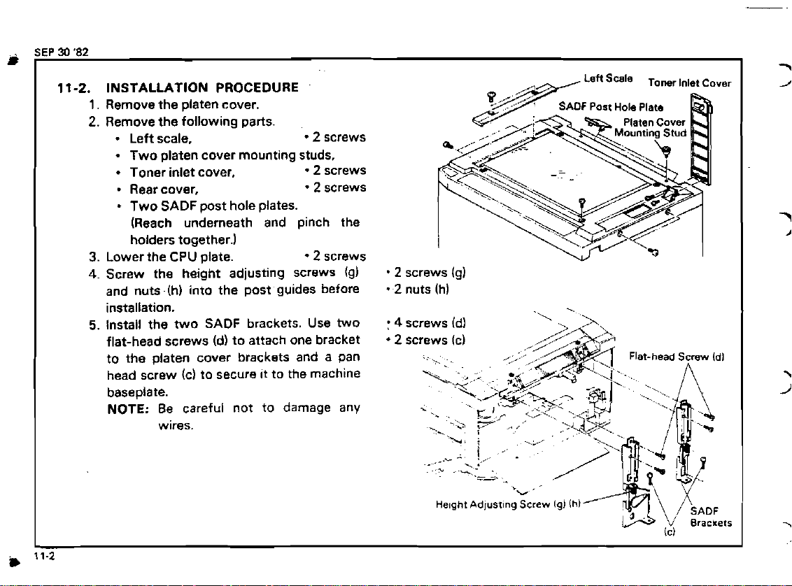
INSTALLATION PROCEDURE
Remove the platen cover.
Remove the following parts.
.
Left scale.
Two platen cover mounting studs,
.
Toner inlet cover.
Rear cover,
-
Two
SADF
post hole plates.
(Reach underneath and pinch the
holders together.)
Lower the CPU plate.
Screw the height adjusting screws (g)
and nuts (h) into the post guides before
installation.
Install the two
flat-head screws
to the platen cover brackets and a pan
head screw
baseplate.
NOTE: Be careful not to damage any
wires.
SADF
brackets. Use two
(d) to attach one bracket
(cl to secure it to the machine
2
screws
2
screws
2
screws
2
screws
-
2
screws (g)
2
nuts (h)
:
4
screws (dl
2
screws (c)
.
. ..
. .
-...
ne~ght
-b
,
r4./
7
!
Adjusting
*,
.
"
,_.
,'
Screw
lgl
'
ihl
Page 5

6.
Install the entrance myler.
NOTE:
7.
Install the black pad on the left of the
upper
8.
Replace the
shown with shoulder screws.
9.
Fix the original exit guide at the left scale
position.
NOTE:
10.
Mount the original feed guide on the
hinge
NOTE
1
1.
Mount the original entrance table together
with the table support bracket on the
right side of the
(Use the two long
Ing the r~ght slde of the top cover
12.
Install the or~g~nal tray (Use the two long
M4
the top cover)
The stainless part of the entrance
myler must touch the exposure
glass holder.
cover at the position shown.
two
t~ss head screws
Confirm that the black pad is
placed just under the hole on the
exit guide.
of
the toner inlet cover.
Check that the toner tank cover
switch is actuated when the original feed guide is lowered.
copler.
M4
truss screws hold-
truss screws securlng the left s~de of
Ongtnal
Exn
Gundo
Black
Pad
2
screws (b)
I
\
~~porureGlass
\
€roosure
\
Glass
Onglnal
/
Holder
/
Feed
/
Guld,
u
Page 6

i.
SEP
#)
'82
13.
Install the SADF by inserting the posts
into
the SADF brackets.
14.
Lower the SADF.
.4
15.
Lightly fix the four SADF post screws If).
16.
Remove the SADF cover.
screws If)
4
screws
-.
17.
Remove the feed belt: (See page
and reinstall left and rlght locktng plates.
1
1-8).
,'
Page 7

18.
Level the
a.
Front Side
The two nylon spacers on the front side
of the
mm
glass.
To adjust the level, move the magnets up
or down slightly.
b. Rear Side
With the height adjusting screws, adjust
the height
clearance between the srays and the
exposure glass is the same on the rear
side as at the front.
SADF
10.08"
SADF
as follows.
should be level and
zt
gtA$lfrom the exposure
of
the rear side so that the
A = 8.
C
=
0.2
D.
k
SUvs
A
-
Exposure Glass
Exposure Glass
Page 8

SEP
30
'82
Confirm that the
c.
On the
the spacers on either side of the original
entrance guide must be the same.
On the left side.
lower exit roller movement as the upper
exit rollers contact them. The amount of
movement should be equal.
19.
Tighten the
20.
Check the front and rear clearances betweeo-the stays and the exposure glass
on both right and left sides again.
NOTE:
21.
If
repeat step
then. install the feed belt.
&ht iide, the clearances between
When tightening the post
screws. rear side- of the clearances will sometimes slightly
change.
the
SAOF
SADF
is level
observe the amount of
SADF
post-screws.
level becomes inproper.
17.
18
and
19
agatn. and
=
Spacer
Upper
Exit
-.
Roller
Page 9

22. Lift the
ness through the hole in the
SADF.
Then. insert the
SADF
SADF
plate.
har-
23. Connect the harness to CN5 on the Main
CPU board and to
CN201 on the
SADF
board. 2P connector
24.
Connect the ACl
OOV
power line. Then.
screw one end of the ground wire to the
SADF,
and the other end to the copier
frame.
25. Tighten the
nylon clips, while lifting the
SAOF
harness with two 7N
SADF.
'
Two 7N nylon clips
2 screws
CAUTION:
If two clamp are installed
while the
SADF
is lowered.
the harness will be pulled
when the
SAOF
is lifted, resulting in damage of the
harness.
(c)
N
Clip
AClOOv
Screw
(il,
Screw
iil
lcl
Line
Page 10

SEP
30
'82
*w
26. Check copier registration before using
the SADF and adjust it if
Adjustment Standard: 2.0
27.
Check SADF registration with the test
sheet as shown
test sheet for five times.
Adjustment
Standard: using the SADF when the
necessaw.
+-
2.0 mlm
in
the right, inserting the
1.5
-c
2.0 mm in average
copier registration is
mm.
+
2.0
10mm
-
Lead Edgn
Registrat~on
LDGJAJ
Sida
to
Side
Regstration
and Skaw
200
mm
Page 11

28.
Adjust registration using
the SADF CPU board according to the
right table.
NOTE:
29.
Mount the SADF cover.
30.
Remount the rear cover of the copier.
31.
Install shoulder screws la1 in the platen
cover stud holes.
NOTE:
32.
Make a final reg~stration and copy Image
check.
33.
Fill out the
tlon Report.
When SW
tion will increase because the DF
motor tums off early.
The flexible platen cover will
be set to these shoulder
screws when book
are made.
DF-10
New Equ~prnent Condi-
DIP SWlOO
#4
is off, the registra-
on
coples
4
screws
2
screws
.
2
screws (a)
#1
#2
1
0
#3
:ON
:
OFF
Change
&
Av
Registration
DIP
SW.
Page 12

*
SEP
I
30
'82
11-3.
FEED BELT
1.
Remove the
2.
Loosen the right locking plate screws and
turn it out
3.
Slide the left locking plate to th right.
REMOVAL
SADF
cover.
4
screws
-
1
screw
SADF
I
Cover
4.
Take
off
the two rubber rings.
5.
Rotate the belt release bracket clockwise.
and slide
off
the feed belt.
.
1
screw
'-4
..I
---
Left
Locking
Feed
Plate
Belt
.-.
,A
.A
Page 13

JULY
20
'82
I
11-
4.
LIFT SWITCH ADJUSTMENT
1.
Check that "Insert Originar indicator
lights.
2.
Lift the SADF and check that "Insert Original" indicator goes off when the distance
between the original stopper and the
bonom
mm and 30
Adjust by repositioning the switch.
3.
Confirm that the original inserted indicator
4.
does not light when lifting
of
the feed belt
mm. (0.63" to
is
up
1
.I
I
between 16
89
the SADF.
 Loading...