

Page 1

RICOH
RICOH
FIELD:
PEMOHT
D6CnYXHBRHIE
9
88
oolnc~oA
TEKHHKH
H
FT4060/FP4030
SERVICE
RICOH
COMPANY,
MANUAL
ITD.
Page 2
Page 3
Page 4
1
1-1.
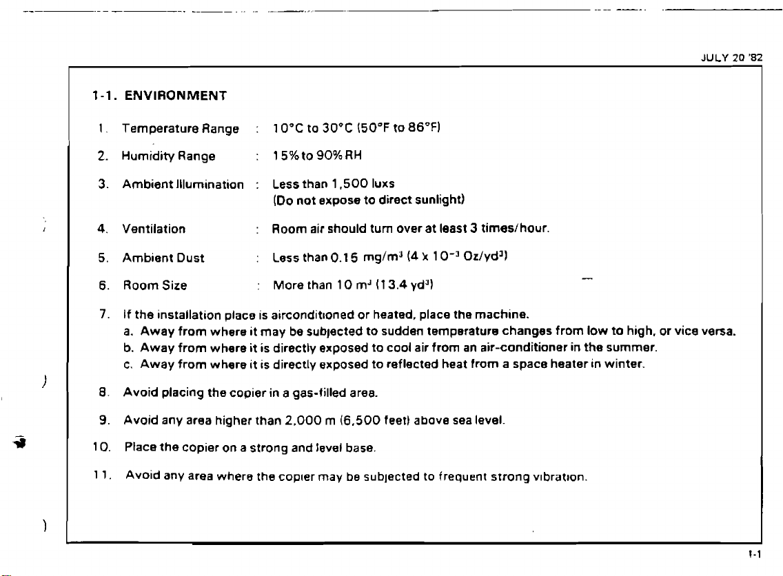
ENVIRONMENT
1.
Temperature Range
2.
Humidity Range
3.
Ambient Illumination : Less than 1.500 Iuxs
4.
Ventilation
5. Ambient Dust
6.
RoomSize
7.
If
the
installation place
a.
Away
from where it may be subjected to sudden temperature changes from low
b.
Away from where
c.
Away from where
8.
Avoid placing the copier
9.
Avoid any area higher than 2,000
10. Place the copier on a strong and level
:
10°C to
:
15%to90%RH
(Do not expose to direct sunlight)
:
Room air should
:
Less than
:
More
is
aircondit~oned or heated, place the machine.
it
is directly exposed to cool air from
it
is directly exposed to reflected heat from a space heater in winter.
in
a
30°C
(50°F
0.1
5
mg/m"4
than
10
mJ
gas-filled area.
m
(6,500
base.
to
86°F)
turn
over at least 3 times/hour.
k
1
0-3
Oz/ydJl
(1
3.4
yd4)
an
air-conditioner
feet) above sea level.
-
to
in
the summer.
high.
or
vice
JULY
versa.
20
'82
I
I
I
I
I
1
1.
Avoid any area where the copter may be subjected to frequent strong v~bratron.
Page 5
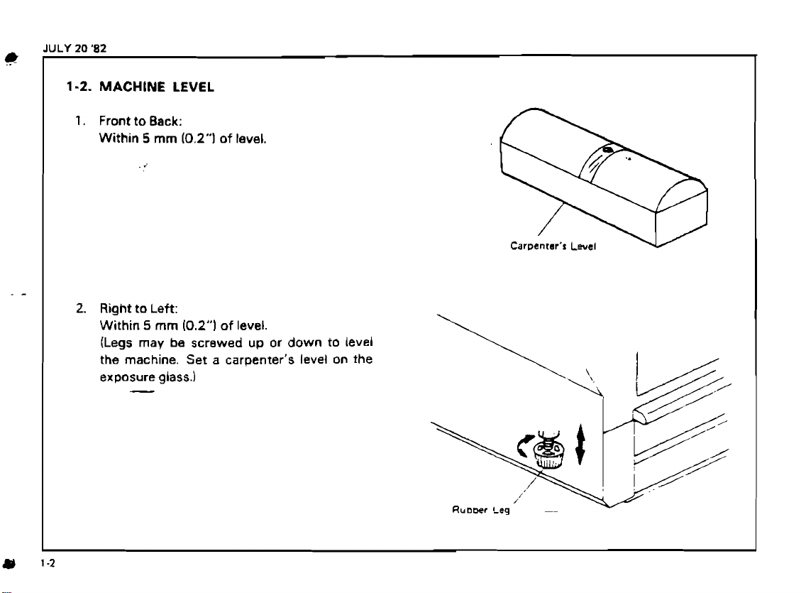
Car~entrr's Level
Page 6

L
'E-
WnWINIW
33VdS
SlN3M13HlfID3U
I
C'I
Page 7
i
JULY
20
'82
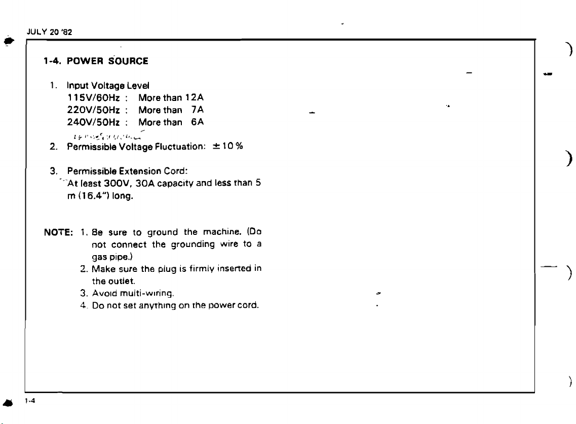
1-4.
1.
POWER
Input
1
15V/60Hz
SOURCE
Voltage
Level
:
More
than 12A
220V/50Hz : More than
240V/50Hz : More than
1
lP%~,..c,
,,I
I./\,L,.-
<
2. Permissible Voltage Fluctuation: = 10
3.
Permissible
--'At
least
rn
(1
6.4")
Extension
300V,
long.
30A
Cord:
capacity
7A
6A
and less
%
than
-
5
NOTE:
1.
8e
sure
to
ground the machine.
not connect the grounding wire
gas
pipe.)
2.
Make
sure
the
plug
is
firmly
the outlet.
3.
Avo~d
multi-w~ring.
4.
Do not set
anyrh~ng
on
the
power cord.
(Da
to
inserted
a
in
Page 8
Page 9

,
-
.
-..
,
.-.A,
2~~~?,~.i*A~.
UNPACKI IN^^^.^^;;;^,^:
.,
-r
-.- . -
....
Unpacking
_
,.
-
,
Accessory
-
..
.
-.
.a.
.
8
,
Procedure,LL;:,.
.-+
,
3*,.,,$@;2;i*::
,
,,
.
~l&k.
-
.;?2<?$':
.
-
+
,.;.
.
,A,
-9.-
,
.:-..
.
-a-
2.''
2-!.
_
-.
2-2.
.-
.
:,
...:...
.:&.
'.A*
..<,
.
%'.
c.,
.,-
.-.:
.
:
-
'4
A:,
,.
A,.;
-1;
I
I.
,
?;:,
.,-;,
-:
.
::;!
.......
.--.-... : ........-... L .......
Is;,'
L.
'
.,
.
-
:
,
-,:
:,-
.-,
"
*::I
..-
c.r,+-,
-
a
A?.
,-
--.
Page 10
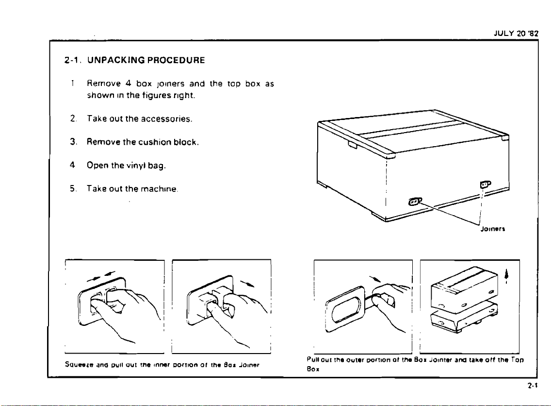
2-1.
UNPACKING
1
Remove
shown
2.
Take
3.
Remove
4
Open the vinyl
5.
Take
PROCEDURE
4
box
lolners
In
the
figures
r~ght.
out the accessories.
the
cushion
block.
bag.
out
the
machtne.
and
the
tap
box
as
JULY
20
'82
I
!
I
I
Jo~nerr
I
?
0
*
Squwzn
ana
pull
out
tne
Inner
I
Dorrron
ot
!he
Bar
Joiner
Pull OUI
80
x
I
the
outer
wrnon
of
the Box
Jointer
am
fake
otf
the
Top
Page 11
SEP
30
'82
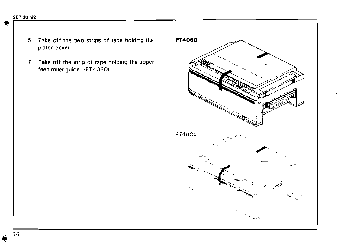
6.
Take off the two strips of tape holding the
platen cover.
7.
Take
off the strip of tape holding the upper
feed roller guide.
(FT40601
FT4060
Page 12
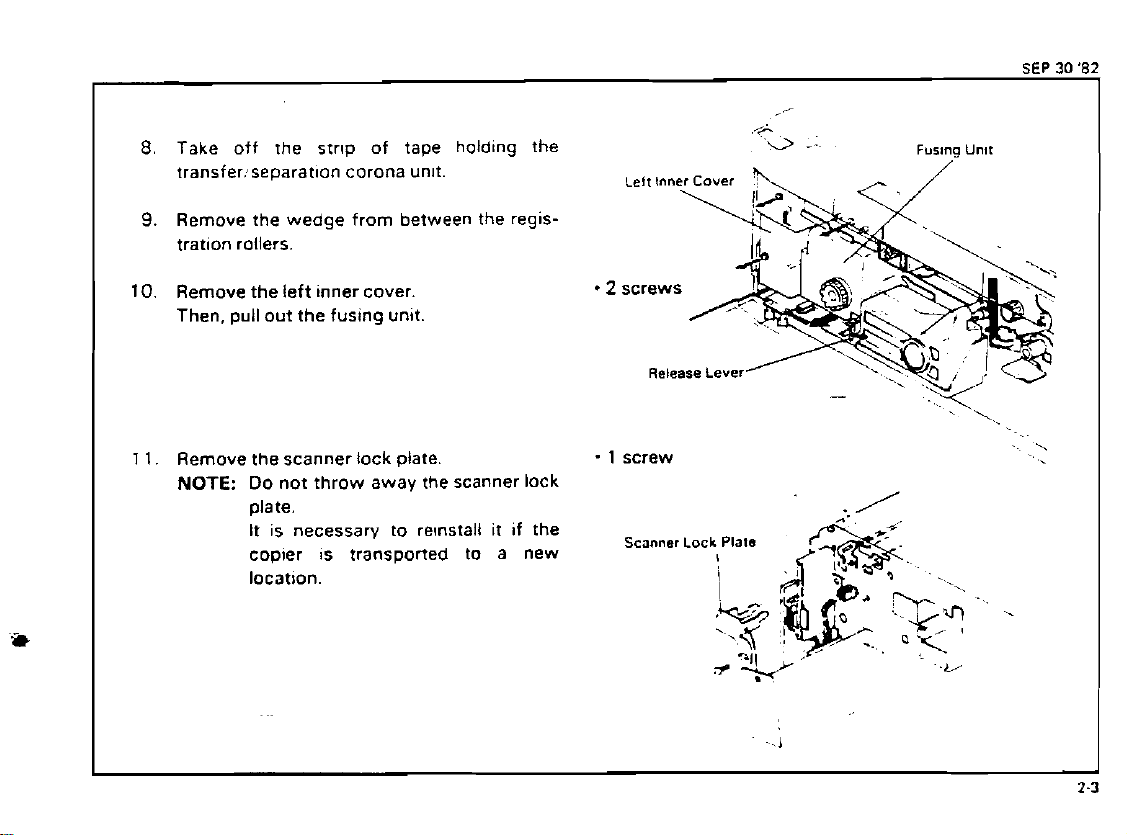
Take off the strlp of tape
transfer:separatlon corona unlt.
Remove the wedge from between the reglstratlon rollers.
Remove the left inner cover.
Then. pull out the fusing unit.
1
1.
Remove the scanner lock plate
NOTE:
Do
not throw away the scanner lock
date.
It is necessary to re~nstall it if the
copier
location.
is
transported to a new
holding
the
-
1
screw
Scanner Lock
Release
Lever
Plats
.I
-
-L/
'..
-.
Page 13
SEP
30
82
i+
1
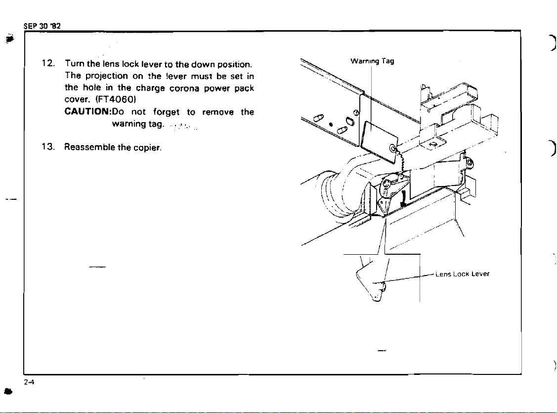
12.
Turn the ,ens lock lever to the down position.
The projection on the lever must be set in
the hole in the charge corona power pack
cover.
CAUTI0N:Do not forget to remove the
13.
Reassemble the copier.
(FT4060l
warning tag.
.
.
...
Page 14
2-2.
ACCESSORY CHECK
Check
cessories in the box according to the New
Equ~prnent Condition Report or the following
list.
10. Toner Collection Bottle
1
1
15. Additional Multilanguage Operating
quantlty and condition of the ac-
1. Large Universal Cassette
2.
Small Universal Cassette
3.
Copy Tray
4.
Original Tray
5. N.E.C.R
6.
Operating Instructions
7.
Operating Instructions Holder
8.
Selenium Drum 1
9.
Cassette Holder
.................................................
..........................................
....................................................
........................................
.......................
.......................
..........................
...........................
1.
Oil Tube
2.
Envelope for N.E.C.R. (1 1 5Vl60Hz)
Instructions, and Decals
1220.240VI50Hz)
Plug
..........................................
....................................
...............
2
(FT40601. 1 (FT4030)
1
1
1
1
1
1
.
2
(FT4060). 1 fFT4030I
1 (Another in the copier)
1
...
1
1
Page 15
.
.,
.
.
.
.
....
.'
,-.-I.
-
.
-.
<
.?,,
.
.
...
-
.
.
,.
.
*..
...
.......
-
?*.
'
..,.
tf-
v
.....
.
.-
-.
-.
..,*,,*:a*J.'.
..
%.
-.
._
.
...
..
..~
.*.
-.
I
I.'
:
*
.'
.,
.
.
........
..-.
Page 16
Page 17
JULY
20
'82
I
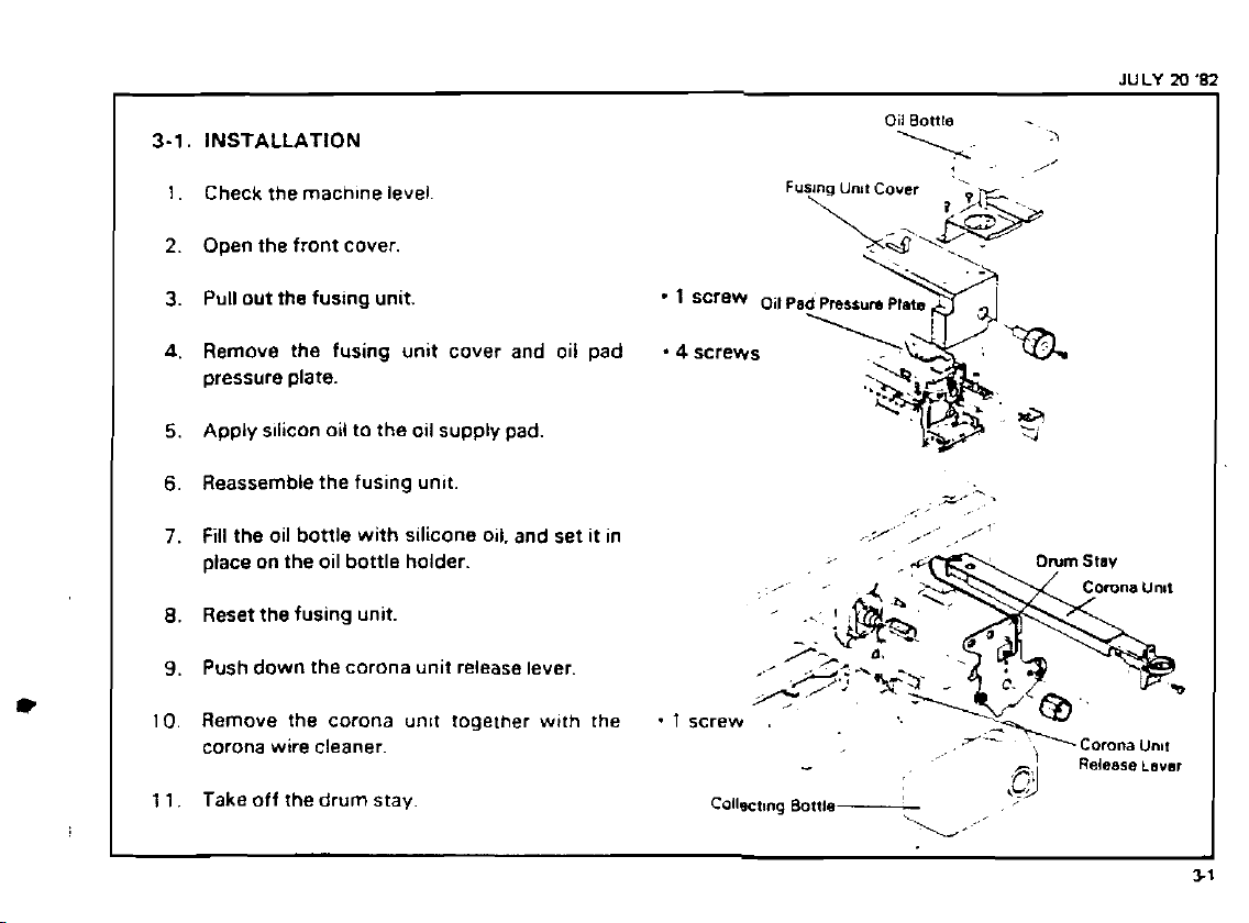
3-1.
INSTALLATION
1.
Check the machfne level
2.
O~en the front cover.
Pull out the fusing unit.
3.
A.
Remove the fusing unit cover and oil pad -4screws
pressure plate.
Apply sflicon oil to the oil supply pad.
5.
6.
Reassemble the fusing unft.
7.
Fill the oil bottle with silicone oil. and set it in
place on the oil bottle holder.
8.
Reset the fusing unit.
Push down the corona unit release lever.
9.
Oil Bottle
,
,..,
\.~
-
'>
.
'
/I
z-
'
.
,
,
/-1
,,
i
I
10.
Remove the corona unlt togelher w~th the
corona wire cleaner.
1 1.
Take off the drum stay.
.
1
screw
Collscttng Bottle
.
Corona
-
,
,L9
\
\;,'
Release
Unnr
Lavar
Page 18
+
JULY
20
'82
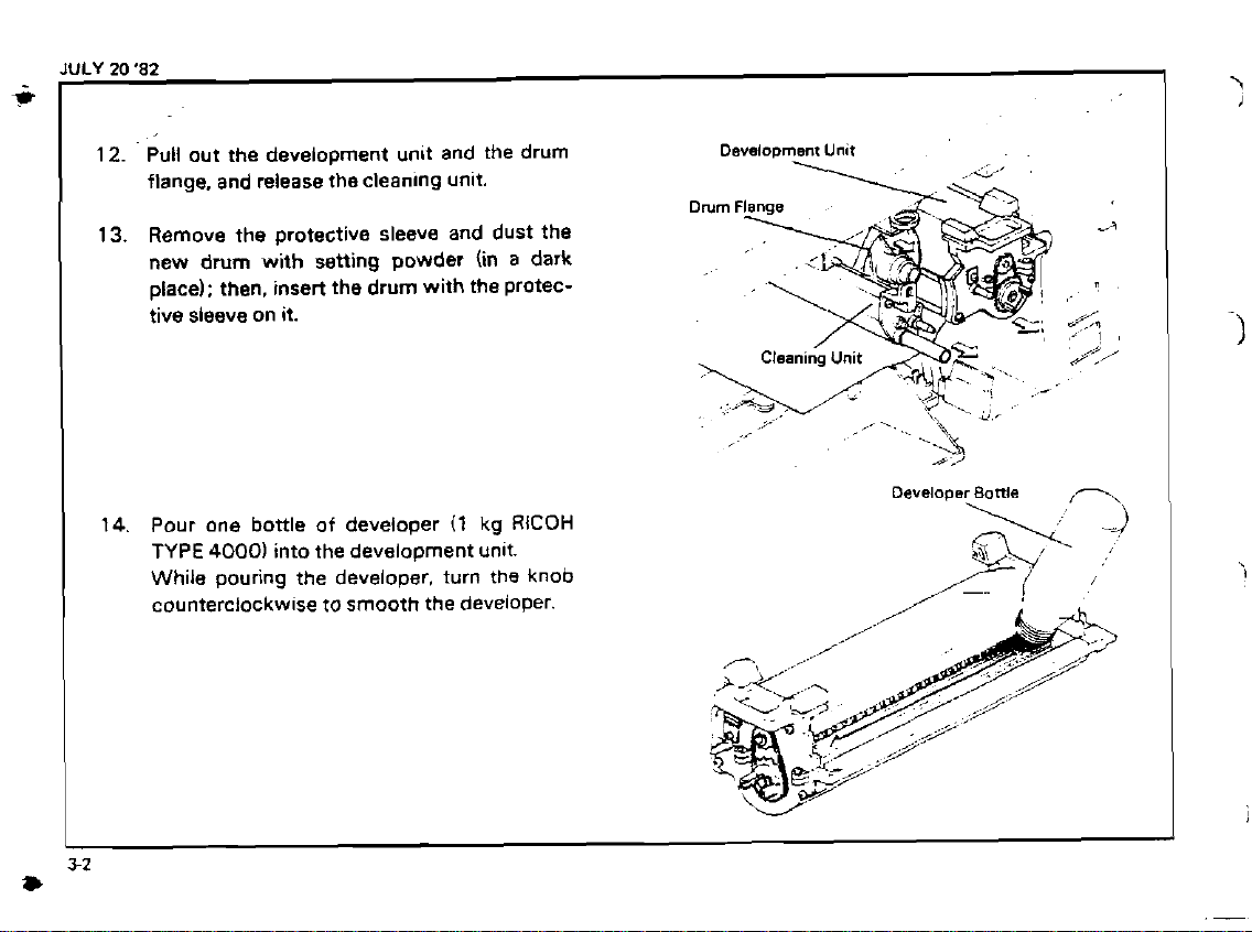
Pull out the development unit and the drum
12.
flange, and release the cleanlng unit.
Remove the protective sleeve and dust the
13.
new drum with setting powder (in
place): then, insert the drum with the protective sleeve on it.
14.
Pour one bottle of developer
TYPE
4000)
into the development unlt.
While pouring the developer. turn the knob
counterclockwise to smooth the
(1
a
dark
kg
RlCOH
deveioper.
Development
Unit
s:'
Developer
Battle
,
I
Page 19
JULY
20 '82
2
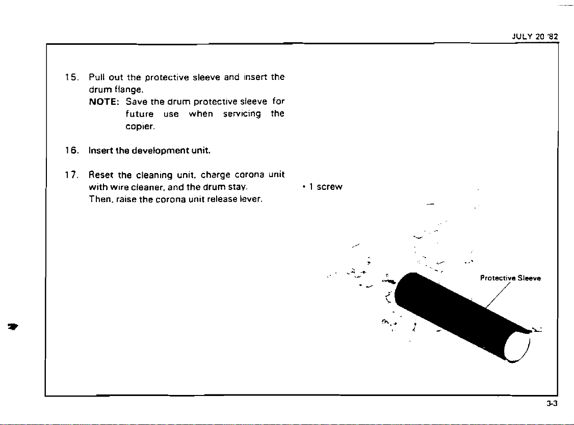
Pull out the protectlve sleeve and Insert the
15.
drum flange.
NOTE:
16.
Insert the development unit.
Reset the clean~ng unlt. charge corona unlt
17.
w~th wore cleaner. and the drum stav.
Then.
Save the drum protectlve sleeve for
future use when
copler.
ralse the corona unlt release lever.
serv~cing the
-
1
screw
-
Page 20
6
.
JULY
M
'82
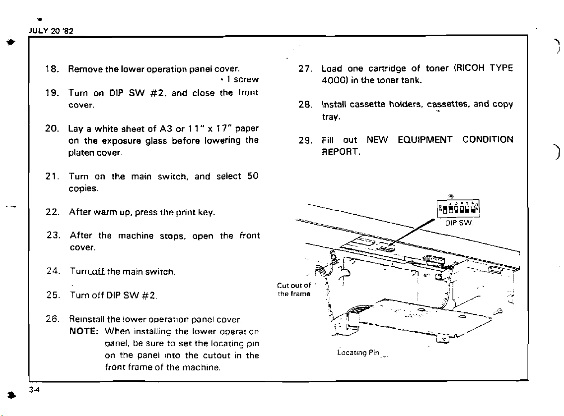
18.
Remove the lower operation panel cover.
.
I
screw
19.
Turn on DIP
cover.
20.
Lay a white sheet of
on the exposure glass before lowering the
platen cover. REPORT.
SW
#2.
and close the front
A3
or
1
1"
x
17"
Paper
27.
28.
29.
Load one cartridge of toner (RICOH TYPE
40001
in the toner tank.
Install cassette holders. cassettes. and copy
tray.
Fill out
NEW
EQUIPMENT CONDITION
Turn on the main switch. and select
copies.
After warm up, press the print key.
After the machine stops. open the front
cover.
Turnnffthe main sw~tch
Turn off DIP
Relnstail the lower ooerarlon panel cover
NOTE: When
SW
#2
~nstalltng the lower operatloll
panel. be sure to set the locatlng pln
on the panei Into the cutout in the
front frame of the
machlne.
50
Locating
1
pin-^
Page 21
I
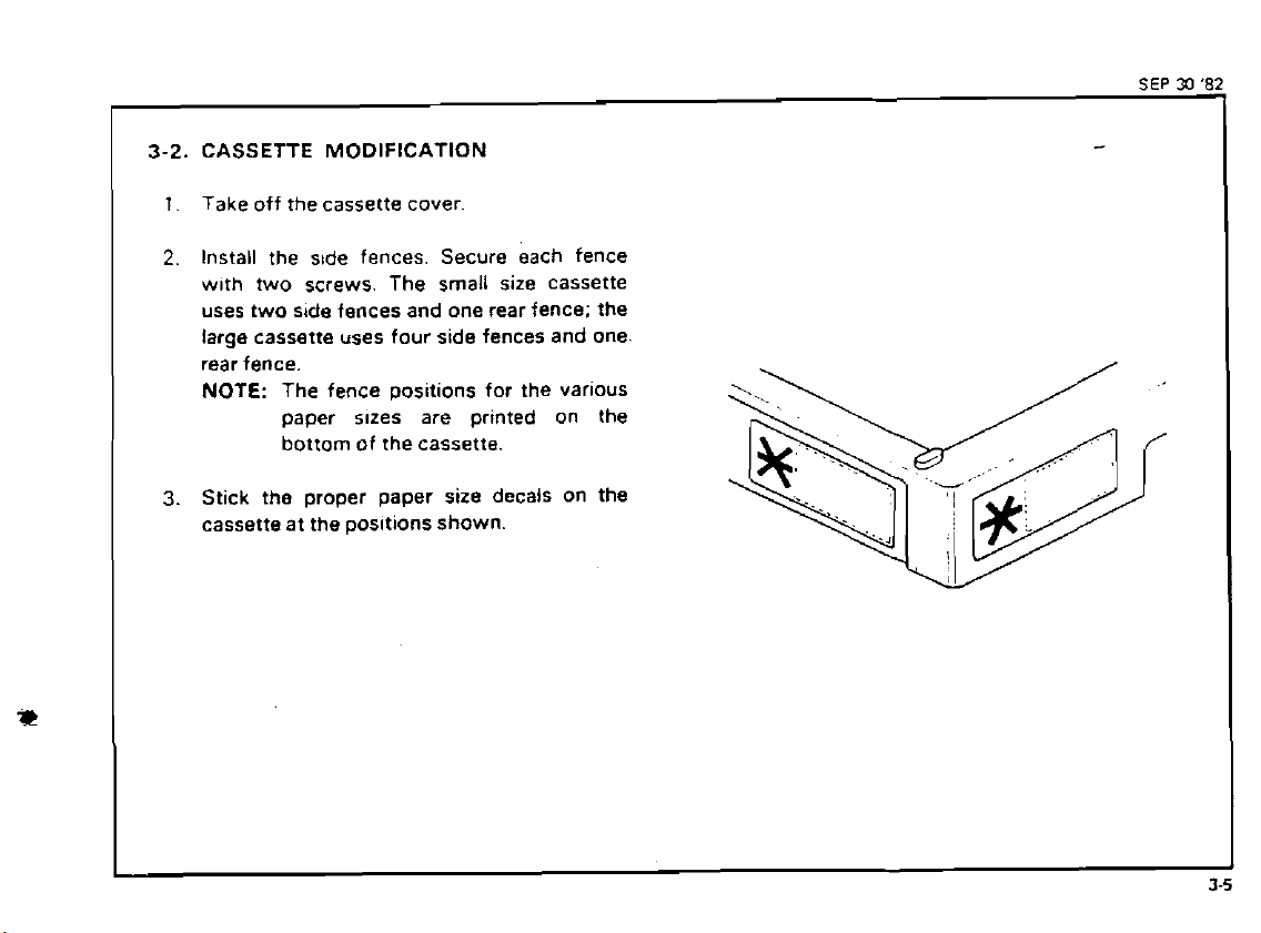
3-2.
CASSETTE MODIFICATION
1.
Take off the cassette cover
2.
Install the s~de fences. Secure each fence
w~th two screws. The small size cassette
uses two side fences and one rear fence; the
large cassette uses four side fences and one.
rear fence.
NOTE: The fence
paper sues are printed on the
bottom of the cassette.
Stick
3.
the proper paper size decals on the
cassette at the
pos~tions for the varlous
positions
shown.
SEP
30
'82
-
!
Page 22
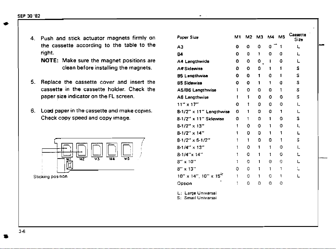
Push and stick actuator magnets firmly on
4.
the cassette according to the table to the
right.
NOTE:
Make sure the magnet positions are
clean before installing the magnets.
5.
Replace the cassette cover and insert the
cassette in the cassette holder. Check the
paper size indicator on the FL screen.
6.
Load paper in thecassette and make coples.
Check copy speed and copy image.
M1
Pawr
Sirs
A3
&)
A4 Lsngthwida
AQSidrmirs
85
Lsngthwisa
85
Saewiu
A5186
Lengthwise
A6
Langrhwira
ll"x17" 01000
8-llt" x 11"
8.112" x 11"
8-112"
8-112 x 14 10011
8-112" n 5-112" 11001
8-114" x 13" 10110
8.114~ 14" 10110
8"
x
8"
x
10 x 14". 10 x 15" 1 0
Option
L:
Lame
S:
Small
Lsngrhw~o
Sidewise
x
13"
10" 1010r)
13" 00111
Unlvarral
Unlvarral
M2 M3
0
0 0 0-1
00100
0
0 0.1 0
00011
00101
00110
10001
11000
0 1 0 0
0 1 0 1 0
10010
10000
M4
M5
Caizp
1
1
0
1
L
L
L
S
S
S
S
S
L
L
5
L
L
S
L
L
L
L
L
Page 23

3-3.
1
KEY COUNTER HOLDER INSTALLATION
1.
For the FT4060 remove the right cover. - 4
For the
cover.
2.
Open the front cover and remove the right
inner cover.
3.
Remove the cover plate and fixing plate
from the key counter bracket.
4. Hold the fixing plate on the inside of the key
counter bracket and
holder.
Align the holes in the fixing plate with the
5.
mounting holes of the
and secure the key counter holder.
NOTE: This copier can use three types of
6.
Remove the shoRlng plug from the key
counter connector.
FT4030 remove the
insert the key counter
key
counter holder
the counter. Make sure to use the
in
correct holes
the fixtng plate.
csv
counter
2
-
3
screws
screws
screws
7.
Plug in the key counter holder.
8.
Reassemble the copier and check key counter operation.
Key
Counter
Holder
.
.
Page 24
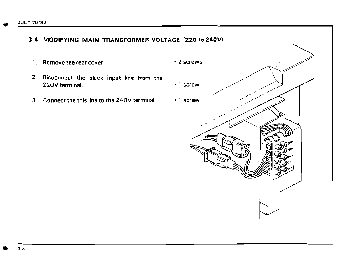
3-4.
MODIFYING MAIN TRANSFORMER VOLTAGE
1.
Remove the rear cover
2.
Disconnect the black input line from the
220V
terminal.
Connect the this line to the
3.
240V
terminal.
2
.
1
(220
tO240V)
screws
screw
\
Page 25
Page 26
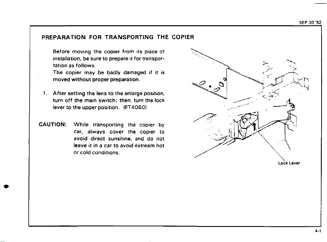
PREPARATION FOR TRANSPORTING THE COPIER
Before moving the copier from its place of
installation, be sure to prepare
tation as follows.
The copier may be badly damaged if
moved without proper preparation.
1.
After setting the lens to the enlarge position.
turn off the main
lever to the upper
CAUTION: While transporting the copler by
car. always cover the copier to
avoid direct sunshine. and do not
leave it in a car to avoid extream hot
or cold conditions.
sw~tch: then, turn the lock
pos~tion.
tt for transpor-
(FT4060)
it
is
,
Lock
Lever
SEP
30
Page 27
**
JULY
20
2.
3.
4.
5.
6.
7
(
1
'82
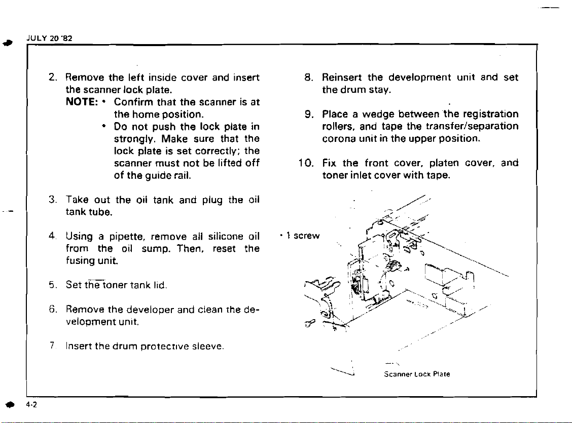
Remove the left inside cover and insert
the scanner lock plate.
NOTE:
Take out the oil tank and plug the oil
tank tube.
Using a pipette, remove all silicone oil
from the oil sump. Then, reset the
fusing unit.
Set tEoner tank l~d.
Remove the developer and clean the de-
velopment
Insert the drum protectwe sleeve
.
Confirm that the scanner is at
the home position.
Do not push the lock plate in
strongly. Make sure that the
lock plate is set correctly; the
scanner must not be lifted off
of the guide rail.
unlt.
.
10.
1
screw
8.
Reinsert the development unit and set
the drum stay.
9.
Place a wedge between the registration
rollers. and tape the
corona unit in the upper position.
Fix the front cover. platen cover. and
toner inlet cover with tape.
'Y
--
Scanner
transferlseparation
,
\
Lock
Plare
-.
I
I
Page 28
*
-
.
,?
._k*.'.
...?$*.;-
,:?h
-.
..I*.<
...
,.;~,.
.,
It
.q%%..ey
.
.
~.
.
-.
.
..
,+-..
.
:-,
.r
::?-
.-
,.(:-..-
I
:e*tx*$y;&,
;
.
.
,
,.
.
'L5
..
-
.
,.'
-. .
~f.
-
=
-
:.
:;,
..
,.,:
.
.Z
-...
.I.
-*
h..
:-..c.
r:,.
.:.s>:
.
.
-
,
,
.
:,
'..
.?
--
.;:
&~$:*~4:#y$*$4::.
.
%.
:.d&;
kaK$<+<.*,&&&::
,
,
. . .
.
'.',~.2
.;:+!'.;-.
.. .
..,..
1
.
.-<.;
:'Y
.
.
:
'
.
:>,
...
1.:,
T
.
.-.
.
.
.
,,<
..:.
,.
.-.
.:
3.
,
,
.
.
.
.
. . .".
.,
41-
,
,
LI.
-
;:
,
,
"L
.
.. .
:
.
.
.
.
.
...
.
--
.
,
-
..
;.
*.
..
.
Page 29
Page 30
5-1.
POINTS TO
Drum Charge
1.
2.
3.
Exposure
1.
2.
3.
REMEMBER
The corona wlres should be cleaned at
servtce call by sliding the corona
every
4.
unit or with dry cloth.
Do not use emery paper or alcohol for
wire cleaning.
Do not touch the corona wires with oily
Launa
used to
a. Scanner Guide Rod (cleaning)
b. Scanner Guide Rod Pads (Lubrication)
011
or an equivalent oil should be
lubr~cate or clean the following
hands. c. Scanner Guide Plate
Make sure that the corona wires are correctly inserted between the cleaner pads.
ILubrication/Cleaning)
d. Lens Drive Screw Shaft (Lubrication)
CAUTI0N:Do not use silicone oil or any
DO not adjust the follow~ng parts:
a : First and second scanner height ad-
lusting cams.
b
:
Scanner Guide Plate
:
Lens AXIS Adjusting Cam
c
:
Lens Posltion Adjusting Screw.
d
:
Fourth Mirror Angle Adjusting Screw.
e
11
screw each1 er and a dry cloth.
(3
screws1
(1
screw)
The scanner home sensor and the lens
home sensor should be
when iewly
installed.
adlusted only
.
,
5.
Clean the exposure glass with glass clean-
6.
Do not touch the following parts with
bare hands:
a.
Reflectors
b. Exposure Glass
c. Mirrors and Lens
7.
DO not adjust the
other kind of
VR
..
on the optics PCB.
Do not bend or damage the lens support
plate or the mylar
strtp.
011.
JULY
20
82
-
~
..
5
Page 31

JULY
20
'82
Development
1.
Be careful not to nick or scratch the development roller sleeve.
2.
DO not turn the development roller in the
opposite direction.
3.
Place a sheet of paper under the development unit when it is out of the copier.
4.
Clean the development unit guide plate
before reinstalling the
Toner
1.
Toner density sensor should be cleaned
everyEM or PM with a blower brush.
at
2.
Do not touch the sensor pattern w~th bare
hands.
3.
Toner density sensor adjustment is required when:
a.
A
b.
The sensor (first quenching unit) is
taken out and reinstalled.
c.
The first quenching
I
5-
2
unlt.
new drum is installed.
PCB
is reolaced.
Cleaning
1.
Do not damage the edge of the cleanlng
blade.
2.
Do
not touch the cleaning brush with oily
hands.
3.
Before pulling out the cleaning unit. place
the sheet of paper under
4.
Be careful not to damage the d~m with
the pick-off pawls when pulling out or inserting the unit.
5.
Toner collected from the cleaning unit
can not be used again.
Second Quenching
1
Clean the lamp surface w~th finger or w~th
a dry cloth.
After
cleanlng it w~th a
charge any static elect~c~ty before
stalling it.
Never use a wet cloth to clean the
lamp.
Paper Feed
1
Lubr~cate the paper feed motor worm
with
Launa
per~odlcally
011
or an
it.
dry
equivalent
cloth, dls-
rein-
E.L.
011
Page 32

Fusing
1
After replacement of the
hot roller. apply silicone
the
011
blade
2.
Be careful not to damage the edge of the
hot roller
3.
Be
strippers.
4
Be sure that the fus~ng lamp 1s not in contact
strtppers or thew tenslon springs.
careful not to bend the pressure roller
Wlth the Inner surface of the hot
011
blade and the
011
to the top of
roller
JULY
20
'82
I
Page 33

5-2. HANDLING THE DRUM
1.
Never touch the drum surface wlth bare
hands.
2.
Store the drum in a cool dry place.
3.
When cleaning the drum, always wear a pair
of glooves.
4.
Always prime the drum with setting powder
after cleaning the drum. or before installing a
new drum. This should be done within one
minute in a
light.
5.
To protect the drum. always apply settlng
poweder to a new cleaning blade and/or
new cleanlng brush before installing them
6.
Drum conditioning
drum is installed. In
done at the
locatlng not exposed to strong
is
necessary when a new
add~tion, thls should be
followtng tlmes:
1)
When image density is reduced due to
overexposure of the drum..
2)
After cleaning the drum.
3)
When thedrum is lightly scratched.
7.
Always keep the drum in the protective
sleeve when inserting or pulling the drum
out of the copier. (Except when applying setting
powder.1
8.
Before insert~ng or pulling out the drum. the
cleaning unit should be pulled slightly out to
avoid drum damage by the
Before lnsertlng the
9
a
drum while
the development
ed whlle the develooment unit 1s In the
comer the edge of the sleeve w~ll scrape developer orf of the development roller
lt
1s
protective
in the cople~lways rake out
unlt If the sleeve is insen-
'
plck-off pawls.
sleeve on the
Page 34

5-3.
TONER COLLECTION BOTTLE
When
toner
remove
servtclng the copler. always check the
collection
it and install a new bottle as follows.
bottle If
rt
is full or nearly full
SEP
30
'82
I
Remove the full bottle and men the cap
1
the month.
Clean the toner collect~on bottle sensor with
2.
a blower brush
Install a new toner collect~on bottle
3
NOTE:
1
I
Each carton of toner
tains three new toner collect~on bottles.
21
The toner collection bottle w~ll'fill in
15K
to
25K
coples.
31
At
each vis~t to the customer gather up
all full toner collect~on bottles. and
return them to the
disposal Jccordlng to local regulat~ons
(1
0
bottles) con-
servlce center for
in
Page 35

Page 36

6.
REPLACEMENT AND ADJUSTMENT
-
6-1. Optics 6-
1
6-2.
Development
6-3. Toner
6-4.
6-5. Paper
6-6.
6-7.
-Fusing 6-55
6-8. Copy
6-9.
.......................................................................................
Cleaning
Fwd
Transport
Image 6-71
Others
..................................................................................................................................................................................
-
*
-
-
6-1
6-25
...
6-31
6-37
6-5
6-81
9
1
Page 37

OPTICS
DEVELOPMENT
TONER
CLEANING
PAPER FEED
TRANSPORT
FUSING
COPY IMAGE
OTHERS
Page 38

6-1.
OPTICS
1
-
1 Exposure Glass Removal 6-
1
-
2.
Exposure Lamp Replacement 6-
2
3
1 - 3. Uneven Exposure Adjustment
1
-
4. Scanner Drive Wire Replacement (FT4060)
1
-
5.
Scanner Drtve Wire Replacement IFT4030)
1 - 6. Scanner Drive Motor Replacment (FT4060) 6-10
-
7
Scanner Or~ve Clutch Removal IFT30301 6-1
1
1
-
8.
Scanner Home Position Sensor Adjustment (FT4060)
1
-
9.
Scanner Drive Belt Tension Adjustment IFT40301 6-14
1-10. Lens Drive Motor Replacement
1-1
1.
Lens Home Position Sensor Adiustment (FT40601 6-1
IFT4060)
......................
6-
6-1
6-1
4
1
2
5
7
Page 39

JULY
20
'82
1-1.
EXPOSURE
1.
Take off the left scale.
2.
Loosen the two screws that tighten the right
GLASS
REMOVAL
glass holder.
3.
Remove the exposure glass.
CAUTI0N:Be sure not to dislodge the three
rubber pads that support the
exposure glass.
Always use two
5)
to the left scale. If long screws
iM4
x
81
are used,
shon-screws
they
scanner, resulting in optia service
call.
(M4
will hit the
x.
Page 40

1-2.
EXPOSURE LAMP REPLACEMENT
1.
Remove the exposure glass.
2.
Move the scanner to the posltion where the
iscut out.
frame
3.
Unscrew the exposure lamp cover and slip it
off to the right.
4.
Rotate the lamp terminal as shown and take
out the lamp.
5.
Install a new lamp.
6.
Check the lamp position and light intensihr.
CAUTION:.
Do not handle the exposure
lamp with your bare hands.
Use a strip of paper as shown.
(Finger marks
the lamp or reflectors will be
affected by heat. resulting in
discolorat~on.)
The prolectlon on the lamp
must
patnt toward the mouth
of the reflector.
1011
marks) on
SEP
30
'82
./
,'
..
-.
V'
,
.
\..
..
.
,
-'..
'
,
,.
,.
-
.a
.r*/:
r/
Page 41

SEP
M
'82
1-3.
UNEVEN EXPOSURE ADJUSTMENT
I. Exposure Lamp Position (First check and
adjust this)
1.
Remove the top cover.
2.
Remove the exposure glass.
Correct the horizontal position by tightening
3.
or loosening the two adjusting screws.
4.
Correct the vertical position by turning the
adjusting knobs.
(Be sure to tighten the ad-
justing knob screws after adjusting the lamp
position.)
11.
Adjusting Plate
If
uneven
exposure still exists after the
above adjustment. do the following:
1.
Remove the exposure glass.
2.
Move the
crease or decrease edge
NOTE:
adjusting
plates as shwn to in-
illuminat~on.
The leading edges of the three
adjusting plates must be aligned
where they meet.
(To avoid white streak.)
.8
screws
..
Adjusting
Plate
Page 42

1-4.
SCANNER DRIVE WIRE REPLACEMENT
(FT40601
1.
Remove the platen cover and the platen
cover mounting studs.
2.
Remove the top cover. 8 screws
3.
Remove the exposure glass.
Remove the rear cover and lower the
4.
plate.
5.
Remove the following parts:
Inlet cooling fan
Platen cover mounting brackets
Bias transformer
NOTE: All screws installed in the horizontal
direction must be short screws
x
6).
Unhook the ends of the wire and take out
6.
the magnification change clamp.
7
Remove the old ware.
8.
Clamp the new wtre to the magnaficataon
change clamp
180 mrn
about
as
shown. The left end is
17.09")
.
CPU
2
screws 1 connector
2
screws each
2
screws 1 connector
IM4
.
1 screw
.
1
screw
Bias
Tranrtormer
180
mm
17
,,
09-1
6
Page 43

JULY
20
4
'82
9.
Reinstall the magnification change clamp.
10.
Move the second scanner to the return
position.
11.
Working from the clamp, thread the long
end of the wire in the lower groove of the
clamp and run it under the inside track of the
tension pulley.
12.
Then, run the wire under the outer track of
the second scanner pulley
the wire clamp
around the lower track of
.
(WPl
)
(WPZ),
(below. the screw), and
WP3.
~,<?,!W
through
*.I
.
1 screw
-
.T
'
Clamp
-
-Second
Scanner
Pulley (WP21
-
13. Run the wire around the outer track of
and then give it three and half (3.51 turns
around the drive pulley starting form the
inside edae.
la.
Next, run the wire over the inner track of
WP4.
track of
-
the lower track of
WP2.
and the innertrack of
WP6,
WP4.
the Inner
WP7.
?.
t&-kL
,
--:
-
-
-.,
k*,
.
c
~-:;
-.
'<
~
.:.-.
3
-
,:<
..
.
,-
15.
Guide the left end of the wlre through the
upper groove of the
clamp; then, pull the ends
er and hook them.
rnagnificat~on change
of
the wire togeth-
Page 44

Tighten the wire clamp. (Be careful not to
16.
bend the bracket.)
NOTE:
17.
Manually rotate scanner drive pulley and
check far overlapping of the scanner drive
wire.
18.
Reassemble the parts removed in step
19.
Check and adjust magnification.
20.
Reassemble the cooier.
Move the first scanner to the posi-
@
tion
scanner to
and then move the second
the position
$1.
5.
Second
Scanner
,
,,
Page 45

1-5.
SCANNER DRIVE
1
Remove the platen cover and platen cover
mountlng screws.
2.
Remove the top cover.
3. Remove the left scale and the exposure
glass.
4.
Remove.the rear cover and rotate the
plate down.
5.
Remove the follow~nq parts:
Inlet coollng fan
Platen cover suoports
Elas
transformer
3emove the ou~lev snarr suoport olare.
.
.
:
.nhoon
tne scanner
WIRE
r,raKP
REPLACEMENT
a
8
screws
2
screws eacn
2
screws 1 connecror
-
4
screws each
-
2
screws 1 connector
2
jcrews
str:o.
CPU
IFT40301
!,"go?
&&?..
...
t
-1
inlet
Cooling
t>
-2"/
.
.-
.
>.,:
%<
A_/
DrcvePullev
Fan
27
,
Y'.&
,
*
.~.
--.\
-
Q.
?
4
.‘,
3%
Pulley
Knob
*.
..
-1
.
-:
.
.:
,.
y.
hai it
Plate
Scanner
,
?...
/
aias
Transiormel
Brake
>
'
Stnp
-sosen [he Nlre
.vlre
c;arno
dilo
remove :ne
'3'0
Page 46

Hook one eno ot :he new wlre to rhe anchor
10
hook.
gun the ,wore unoer the lnsloe track of WP1
i
1
and around the lower track of WPS.
i
2.
Next. run the Wlre over the lns~de track of
WP3.
13.
Run the wlre over the pulley, and wrap
around the pulley
the inside edge of !he pulley.
Then, run the wlre over the outer track of
14
WP3 and around the lower track of
Run the wlre through the wlre clamp tbelow
IS.
the screw) and over the outslde track of
WP1.
16.
Hook the free end of the w~re to the tension
bracket.
17
Tighten the ware cl3mp.
NOTE:
Manually rotate the main pullev and check
18.
;or overlapD!nq
.
Be cxerul not tobend the bracket.
Seepaqe6-7
3-1
2
times. starting from
=16
ot
the scanner urlve wlre.
WPZ.
.
<
WP2'
I
'Nlre
Clam0
,
it
Maln
..
WP~/\\ Wire
-..
-..
.,I\\.
..
\,-
-
A,
,'/P3
.
'.
.
.
Pullev
Secona
Pulley
Anchor
'
;.
.
-5
,3kT
Scanner
IWPlI
Hook
Clamu
Tenston
,
'
-
a
..
-2..
-.
SEP
Bracket
.
..
Y
30
'82
:
Y
fieassemole the cooler
19
check and aulust rn3gnlilc3t1o1i
-%
*,,.I,~
P,,,I~V
;~:cu,w
?,II'FV
Sc~iuier
lWP"
6-9
Page 47

JULY
..
.
.
20
'82
1-6.
SCANNER DRIVE MOTOR REPLACEMENT
1.
Take off the rear cover and lower the
plate.
Take off the top cover. and remove the
exposure glass.
Remove the right cover.
Uncouple the scanner drive motor connec-
tors and unscrew the ground wire.
Tape the drive wire to the pulleys as shown
to the right.
CPU
2
screws each
8
screws
2
studs
-
4
screws
(FT4060)
Slide the
Replace the scanner drive motor.
maln oullev off of the motor shaft
2
allen screws
.4
screws
Main
-/
~"llev
Page 48

'-7.
SCANNER DRIVE CLUTCH REMOVAL
;zke
oif
the rear cover an0 lower tne
3!~:e
2.
Take off the ~nlet cool~ng fan.
3.
Take off the ma~n pulley knob.
-I
Semove the pulley shaft support olate
5.
Unhook theclutch brake strlp.
5.
Tdpe the wlre lo the ma~n pulley and
and unhook the wlre
i
Take off the maln pullev
Slio the scanner dr~ve belt off ot the oullev
3.
shaft
.
7-111,.p
'C?
-.
scanner
tightener
O:lvr
:Iutc!l
sprlng.
IFT40301
CPU
2
screws each
-
2
screws
.
1
E-r~ng
-
2
screws
WP3. .-. .
WP~--~
~a~n
~ullev
.
:
-:-
2
,.-
,
2
allen screws
:
;crr?~vs
'
connector
Z
wtre
P
cl,imps
..
y,
Scanner
Dr,ul:
..:,
-
*'..
7-
.,
Sc~nnrr
Clurcl
.
. .
~.
-,T
'.
..\
-.
.;'.;
,;45,$>.,.3
.
.I(;
,,
:
.-,
'.
Y
P
,
-.
Orwe
Belt
Page 49

SEP
30
'82
1-8.
SCANNER HOME POSITION SENSOR ADJUSTMENT (FT4060)
1. Select full size mode.
2.
Take off the rear cover and lower the
plate.
CPU
2
screws
M3
Truss
Screw
3. Turn the main pulley to move the scanner
until the center of the M3 truss screw is 14
mm 10.55") from the left scale.
4.
Connect the digital multimeter input line to
4
pin
CN403-05). and connect the multimeter
COM line to logic ground. (The wire securing
OSCl is good for this.)
5.
Remove the plate from the access slot
above-the home position sensor.
6.
Loosen the home position sensor screw.
Slide the home position sensor just to the
7.
point where the multimeter changes from
OV
Tighten the sensor screw at this position.
CAUTION
of IC21 on the optics PCB lor
-
to +5V.
Be careful not to damage
pattern.
-
El
PCB
...~
..
.
i
scanner
Poslrron
.
~
"
i
Home
Sensor
-,P
'-LC-&?
+--
-r
b
"
.
.
-
Y'
,.
,
,.
Page 50

8.
Check the adjustment:
Move the scanner away from the home
position until the multimeter changes to
low.
it
Then slowly move
back until the multimeter turns high again.
Check that at this position
0.5
mm.
(0.55" ? 0.02")
-@I'
is
14
SEP
JO
7
I?:
NOTE:
When the home .wnsor is properly
positioned. the lead edge margin (erase.
and registration) will be almost equal for
all five magnifications.
Page 51

JULY
20
'82
-.
SCANNER
Adjustment Standard: 750
Remove the top cover.
Take off the inlet cooling fan
Loosen the belt tightener bracket screw.
Pull up on the belt
tenslon gauge. Tighten the bracket screw
when the gauge reads 750 g (1.65
NOTE:
DRIVE
Make- sure the lower end
t~ghtener bracket 1s in the gu~de slot.
BELT
TENSION
(1.65 2 0.55 lbs)
t~ghtener bracket w~th a
ADJUSTMENT
t
250 g
lbs).
of
the
-
8
screws. 2 studs
-
2
screws
(~~40301
,m-
-
750
,,
-
.
-
11
-
,'
*
I!
i+)
Scanner
/
Drwe
Belt
Page 52

'2
440
aye1
.ajeld
.
nd3
eq) lamol pue JaAoa leal aq;
q3ea smelas
.&
.p
.g
.g
A'/
Bulse3
WNQ
,-
3-
enoqpr
4
-
~
&.
-
&
aq; 6uuna%s
suoloa afi~eq:, pue janp i!e aqj enowau
sme~as
SMaJlS
>
.
..
,
.-
@
s~a~as orm aqt a~owen
.bu!se:, wn~p a~oqe eqa lo ep!s leer
'JaAO3 qaed Iemod
'aleid Aeas wnlp aq~ijo aye1
.6u1se:, wnlp moqe aql lno eyel
Page 53

7.
Remove the light shield cover.
8.
Disconnect the lens drive motor connector
it
and disengage
9.
Unscrew the two wire clamps holding the
lens drive motor harness.
10.
Remove the lens drive motor assembly.
1 1.
Take off the motor cover.
12.
Remove the motor gear.
13.
Replace the lens drive motor.
14:
Reassemble.
from the rear side plate.
3
screws
2
screws
1
screw
-
1
alien screw
2
screws
Mot
Page 54

1-1
1.
LENS HOME
1.
Remove the exposure glass, light shield
cover, and rear cover.
2.
By tumlng the lens drive shaft. move the
lens to the position where the center of the
cam follower is aligned with the two holes in
the second scanner drive cam as shown.
Connect the multimeter's COM line to logic
3.
ground and connect the input line to'pin
of lC2l (orCN403-A71.
4.
Loosen the sensor fixing screw
5.
Slide the sensor as far as posstble toward
the right.
6.
Slowly slide the sensor back unt~l the multimeter readlng changes from
Tighten the sensor screw at thts posltlon.
7.
Make a copy and check the hor~zontal
component of magn~ftcatton.
NOTE: If the resolutton or focus becomes worse when the wlre clamp lhor~zontal rnagntf~catlon) 1s
correctly posttloned. ~t 1s necessary to adjust the lens home sensor.
POSITION SENSOR ADJUSTMENT
-
2.3.
10
+5V
to
OV.
(FT4060)
and 2 screws
Lena
Horns
Pos#tton
Sensor
Dr~vs Cam
~s&
I
Drira
Shan
SEP
30
Page 55

6-2.
DEVELOPMENT
JULY
20
'E
2-1. Developer Replacement
2-2.
Doctor
2-3. Magnet Angle Adjustment
2-4.
Bias Power
Gap
Adjustment
Pack
...........................
Check 6-23
......................................................................................
..
.....
............
6-20
6-2
1
6-22
Page 56

SEP
30
'82
2-1.
DEVELOPER
1. Insert the end of the development unit in a
vinyl bag and hold it as shown.
2.
Turn the development unit knob counterclockwise.
The developer will fall into the bag.
3. Reassemble the paddle gear and idle gear.
4
After dumping the developer. check the
movement of the vibrating plate. The
paddle roller should move
10 mm. (0.08" to 0.39")
I.
1
Pour one bottle
development unlt wile turnlng the develop-
rnentunit-knob.
CAUTION:.
REPLACEMENT
it
about 2 mm to
il
kg) of developer into the.
-
Be careful not to bend the bias
terminal.
-
After removing used
developer. clean
gears.
the
drive
A
1
,/
ye&,
-A
g
Plate
I
I
pad&
Roller
I
Page 57

i.
i;
2-2.
DOCTOR
.
Adjustment Standard: 1.26 f 0.1 mm
1. Take out the development unit and empty
the developer.
2:
Take off the upper cover. 2 screws
3.
Before making the adjustment. confirm that
both surfaces where the thickness gauge
will
4.
Loosen screws @ and
5. Insert a 1.26 mm (0.05") thickness gauge
into the
press the
blade lightly contacts the doctor blade.
G&
ADJUSTMENT
be
inserted are clean.
DG
at the shown positions, and
DG
plate down until the doctor
(0.05" 2 0.0041
@.
J
~.
--
-
--
~
.-
----
-
JULY
20
'82
.<>':
DG
Plate
6. Tighten screws
7.
Check that the
both positions.
NOTE:
Confirm that the
whenever the upper and lower sections
seoarated.
!@
and
'01.
DG
is correct and even on
DG
is correct
of
the development unit are
@
@
Page 58

*
I
JULY
20
'82
2-3.
MAGNET ANGLE ADJUSTMENT
1.
Loosen the magnet plate screw. and turn the
magnet plate
possible.
2.
Turn
the plate slowly
one graduat~on to the left
NOTE:
Adjust the magnet angle after
replacing the development roller.
counterclockw~se as far as
clockwise
of
center.
and fix
-.
-
-
-
-
it
-
-
Page 59

I
2-4.
BIAS
POWER PACK CHECK
1.
Tuin off the bias thermistor swltch and turn
on the free run switch
2.
Set the density control at the center (4th)
position.
3.
Press the print key; then. with a digital
multimeter, check the development bias. At
the center setting, the bias should be
f300V 2 12V
4.
Check that the bias value changes approxi-
60V
mately
If the bias value is incorrect. disconnect the
5.
bias cable and check bias output directly
from the cable.
If the bias is now correct. check for a bias
leak from the development roller.
.
If
the bias is stdl wrong. replace the bias
power pack.
at each step.
(DIP
SW100
during forward scan.
#ll.
DC
Bias
Power
Pack
SEP
30
'82
-
L-
NOTE:
When the therm~stor sw~fch
becomes
f~xed at the
30°C
value.
IS
off, the bias temperature
compensation
w~ll not work, and output
-.
-
623
Page 60

6.3
. TONER
3.1 . Toner Density Sensor (First Quenching Lamp) Replacement
.
Toner Density Sensor Adjustment
3.2
3.3
.
Toner Tank Removal (FT4060)
3.4 . Toner Tank Removal lFT4030)
.-
....................
..
.....................................................................................................
...........................................................................
......................................................................
-
. .
..
6-26
6-28
6-29
6-30
Page 61

JULY
M
'82
3-1.
TONER DENSITY SENSOR (FIRST QUENCHING LAMP) REPLACEMENT
1
Lower the transferlseparation unit.
2.
Take off the charge corona unit and the
.
1
drum stay.
3.
Take out the toner collection bottle and the
cleaning unit.
4.
Take out the development unit and put
a clean sheet of paper.
5.
Slide the protective sleeve over the drum
and take off the drum flange.
6.
Pull out the drum and the drum heater.
7.
Remove the rear cover
plate.
8.
Remove the wlre clamp and clamp bracket.
and disconnect the two harnesses
3P) golng
to
the first quenching unlt.
and
lower the
(5P
screw
it
on
. 1
C-ring
CPU
2
screws each
and
5P
Connector
626
Page 62

9.
Pull the connectors and wires through the
rear side plate.
10.
Take out the first quenching assembly.
1
1.
Remove the wire clamp and loosen the two
screws on the first quenching assembly.
12.
Replace the first quenching P.C.B.
13.
Reassemble the copier and adjust the toner
density sensor.
NOTE:
Make sure the rear end of quenching
assembly is properly set in its
bracket.
.
2
I
screws
screw
'.
'.\+,
.:I!.
;-4
..,
Page 63

SEP
3
&
"82
3-2.
TONER- DENSITY SENSOR ADJUSTMENT
1.
Clean the following parts.
Toner density sensor with blower brush or
solder sucker.
Optics Mirrors and reflectors with silicon
cloth.
Lens with blower brush.
Toner shield glass with
Charge corona wire with dry cloth.
2.
Place 2 or 3 sheets of
exposure glass.
3. Select drum conditioning mode
under the operation panel).
4.
Insert small paper clips in CN3-613. and
CN3-Bt4 on the main PCB while the main
switch is off.
NOTE: Cut the end of the clips to a point to
make
it
easy to insert.
CAUTION:
8e careful not to let these two
clips contact.
LDGlA3
dry cloth.
paper on the
(DIP
SW
#2
FT4030
FT4060
Maln
PCB
.
.Is£.
d<
14
014
'V
Page 64

5. Turn on the main sw~tch, and wa~t for warm-
1
6.
After warm-up. turn off the main switch and
connect the multimeter and short wire as
follows;
FT4060 Multimeter Hot line: CN3-B13
1
Short wire: CN3-B14 and TP100
FT4030 Multirneter Hot line: CN3-614
I:
Short wire: CN3-813 and TPlOO
CAUTION
7.
8.
9.
Apply tape to TPl 01 and TP102 to
prevent electrical shortage of these
two pins to
Turn on the maln switch. set 50 copies. and
select the 3rd level of
Press the punt key. and check the voltage
durlng the forward scan.
Adlustrnent Standard:
Adjust the
quenching unit.
Lround line: TPl 00
TGround line: TPlOO
,
,
8.
TP100.
dens~ty connol.
4
0
f
0.2
VR
on the front end of the first
I
V
6.28.1
Page 65

3-3.
TONER TANK REMOVAL lFT4060)
1.
Remove the top cover.
2.
Remove the right cover.
3.
Take off the inner right cover.
4.
Take off the rear cover and lower the
plate.
5.
Remove the hamess cover.
6.
Take off the right side plate.
7.
Put a sheet of paper on the upper feed roller
to catch any dropping toner.
8.
Take out the toner tank.
-
8
screws
2
studs
4
screws
3
screws
CPU
2
screws each
5
screws
4
screws
1
connector
1
ground wire
4
screws
2
connectors
Harness
a
Cover
-
Page 66

I
3-4. TONER TANK REMOVAL IFT403OI
1.
Take off the top cover and inner right cover.
2.
Remove both right side covers.
3.
Remove the rear cover and lower the
plate.
4.
Take off the by-pass paper guide.
I
5.
Remove the right side plate.
6.
Remove the harness cover.
7.
Remove the by-pass entrance brace.
Put
a
3
9,
sheet of paper on the by-oass feed
roller to catch any dropping toner.
Take our tne toner tann.
CPU
-
4
screws
2
connectors
1
ground wire
2
screws
.
4
screws
1
connector
-
d
screws
2
connectors
8
screws.
2
studs.
3
screws
2
screws each
2
screws each
.
1
screw
.
Toner Tank
I
I
I
Page 67

Page 68

4-1.
CLEANING
1.
Take out the cleaning unit.
2.
Remove the old blade.
3.
Dust a new blade with setting powder.
NOTE:
4.
Install the new cleaning blade.
CAUTION:
BLADE REPLACEMENT
Clean the inside
Be careful not to touch the edge
of the new blade.
of
1
the cleaning unit.
screw
Page 69

4-2.
PICK-OFF PAWL REPLACEMENT
1.
Unscrew the cam holder. Be sure to grasp
the inner part of the holder when
unscrewing.
2.
Remove the pawl shaft pin.
3.
Remove the spring.
4.
Remove the cam rider.
5.
Take off the old pawls and slide new pawls
onto the shaft. Do
6.
Fix
the spring.
NOTE: The spring screw must enter the
shaft from the top.
IOposite side from the pawl pins.)
Set the pawl shaft. Make sure the sprlng
7.
end is in the small hole.
not set the E-rings yet.
.
1
screw
1
allen screw
Page 70

8.
Tighten the spring by rotating the shaft
counterclockwise viewed from the front
2
(about
shaft pin.
9.
Set the cam rider.
10.
Set the pawls and fix them in place with the
E-rings.
1 1.
Screw in the cam holder.
12.
Check that the
the pick-off pawls is smooth by pressing the
pawl shaft pin to the black arrow direction.
turns); then, screw in the pawl
up
and down movement of
NOTE:
Before pressing the pawl shaft pin, the
pa& should be in the down position
(white arrow position).
Page 71

4-3.
CLEANING BRUSH REPLACEMENT
1.
Remove the front bushing from the front
end.
2.
Remove the gear and rear bushing from the
rear end.
3.
Take off the brush shaft holder, and takeout
the old brush.
NOTE: Clean the inside of cleaning unit.
4.
Prime a new brush by dusting :'with setting
powder.
NOTE: Do not touch the new brush: handle
the shaft only.
5.
Install the new cleaning brush.
.
.
1
1
2
E-ring
E-ring
screws
Clesnlng
Brush
Shaft
,
.
Holder
Rasr
~ushing4
Yp
Gear4
-.
.
..",l
"KT
JULY
a,
20
'82
Page 72

JULY
20
'82
4-4.
TONER COLLECTION COIL REPLACEMENT
-.
I
1.
Take
off
the coil gear.
2.
Remove the old coil and insert a new one.
3.
Reassemble.
.
1
E-ring
-
-
Page 73

6-5.
PAPER
FEED
JULY 20
82
Feed Roller Replacement (FT4060l
5-1.
5
-2.
Feed Roller Replacement (FT4030) 6-39
...
:
....................................................................................................................
6-38
-
...
.,"
?<,,'
w
..
.-
5-3. Friction Pad Replacement
Paper Feed Adjustment
5-4.
5-5.
Upper By-pass Feed Roller Replacement IFT40301 6-43
5-6.
By-pass Feed Solenoid Position iFT40301 6-45
5-7.
Upper Paper Size Detector Replacement (FT4060) 6-46
5-8. Lower Paper Size Detector Replacement
5-9. Paper Size Detector Replacement (FT4030l 6-49
5-1
0. Crimp Clutch Adjustrnant
.
.
.............................................................................................................................................
..........................................................................................
(FT4060)
................................
...........................................................................................................................................
.............
.
~
.
.
..
....................................................
-
-.
-3s
'33
J,,'-64,,
t)r?
.
-
6-41
6-48
6-50
-
-
.
.
Page 74

*
JULY 20
I
.
5-1.
'82
FEED ROLLER REPLACEMENT
1.
Loosen the feed roller allen screws, and slide
the feed roller off the shaft.
2.
Install a new feed roller.
The end of the feed roller must be flush with
the end of the roller shaft.
NOTE:
Removal procedure
both upper and lower rollers. For
access to the upper roller, first
remove the upper front guide plate.
lFT40601
is
the same for
I
-2
Feed
/
Roller
'<\
Upper
Front
b
Guide
Plate
Page 75

5-2
FEED
ROLLER
1.
Open the front cover.
2.
Remove the r~ght Inner cover, and remove
the feed roller shaft
3.
Remove the cassette holder.
4.
Loosen two feed roller allen screws. and
push the feed roller to the front end of the
feed roller shaft.
5.
Take off the rear cover.
6.
Turn down the
7.
Push the roller shaft out to the rear about
60
mm
(2.36").
roller off the front end of the shaft.
Be careful not to damage the paper end
detector feeler or actuator.
8.
Sltde a new feed roller on the shaft and
reassemble.
REPLACEMENT
bushlng.
CPU
plate.
and slide
the
lFT40301
2
screws
-
1
E-ring
2
screws
-2
screws
old feed
'i
Cgea
NOTE:
Roller
When installing the feed roller.
the
allen screws should be tight-
ened at the extreme left of the
positioning
. .
.
Fasd
Rolhr
Shaft
groovax
..
,
>
!>st2
.:.,,,>
./
I
Page 76

s
SEP
33
5-
'82
3.
FRICTION PAD REPLACEMENT
1.
Remove the friction pad bracket.
2.
Strip the worn friction pad off the bracket.
3.
Stick the new pad in place.
Check that is
(0.002"
NOTE:
4.
Before remounting the friction pad bracket.
grease point
NOTE:
to
0.01
Do not touch the surface of the
friction pad.
@.
Check the swivel movement
of the bracket.
0.05
to
4)
(Swivel point)
0.35
mm.
'
1
screw
Friction
Pad
Page 77

SEP
30
'82
I
5-
4.
PAPER FEED ADJUSTMENT
i
Adjustment Standard:
Upper Cassette: 150
2
mm (5.91
35 0 59.
"
2
0397
Lower Cassette: 135
<,
?,
,
7
%
'O
mm 15.31"
I5
[Rough Adjustmantl
NOTE: This adjustment
is
required only after re-
placement of the paper feed PCB.
1. On the Main CPU board connect
IC300-10 (or CN102-811 for FT4060.
CN102-813 for FT40301 and TPlOO
(GND). (When the main switch is turned
on, the paper feed motor will
continuously. so turn down the upper
cassette handle.)
2. Turn on the main switch. Measure the voltage between
CN2-1
(+I
and CN2-3
on the paper feed P.C.B.
Adjust this potential to
+
16.5V + 0.5V
w~th VR1
3. Remove the jumper line from the Maln
CPU board.
?
0397
0
run
(-1
59-
Page 78

JULY
20
'82
0
[Fine
Adjustment1
NOTE:
2.
3.
4.
5.
Before adjustment, clean the paper feed
rollers and friction pad.
1.
Remove the cover from the large
universal cassette and insert
upper position.
Make three
momentary stop position of the trailing
edge for each sheet (On the sheet
underneath).
Measure the distance from the mark to
the trailing edge of each sheet (This is the
paper feed amount) and compute the
average.
If the paper feed amount is outside the
standard adjust with
After adjustment, insert the cassette in
the lower position and check that the
lower feed amount is correct.
A3
(LDG)
copies. Mark the
VR
1
it
in the
\
Page 79

5-5.
UPPER BY-PASS FEED ROLLER REPLACEMENT lFT40301
1.
Open the by-pass feed table. and remove
.
1
.2
screw
screws
the by-pass paper guide.
2.
Unhook the support arms and let the by-pass
feed table hang straight down.
3.
Take off the key counter cover.
4.
Open the front cover and remove the right
inner cover.
.
-
JULY
20
'82
..
.
5.
Take off the rear cover and lower the
plate.
6.
Remove the harness cover.
7.
Disconnect the by-pass feed sensor 3P
connector.
8.
Remove the by-pass entrance brace.
CPU
2
screwseach
2
screws
4
screws
w
R'ght
/
'-
her
Cover
uey
counter
Bv-pass Paper Guide
Bvpass Entrance Brace
cover
Page 80

JLY
20
10.
1
12.
13.
'82
9.
Remove the front bushing.
Remove the by-pass roller gear and the
rear bushing.
Take out the feed roller shaft.
1.
Replace the entire by-pass feed roller
shaft
as
a
set.
Reassemble.
-.
1
E-ring each
-
/
Feed
Roller
Shaft
-
.
.
.<
.A
'L
-
.
y
..
.
;
"
e;;s
.
Page 81

5-6.
BY-PASS
Adjustment Standard.
1
Take off the rear cover an0 lower the
CPU
SOLENOID POSITION (FT40301
0
5
to
1.0
(0.02"
to
plate.
mm
0.04")
2
screws each
2. Push
3.
4.
5.
In the plunger of the by-pass soleno~d and check that the clearance between the rubber
to 1 0 mm
If ~t 1s not. do the follow~ng
Loosen the solenoid bracket screw.
lnsen a 0.5
between the
of the plunger.
Push up the plunger untll the by-pass
feed rollers
tighten the bracket screw.
10
rlng and solenold 1s 0
02" to 0 04")
mm
(0.02")
solenold and the rubber rlng
lightly
thickness
touch. At that posltlon
5
gauge
Page 82

+-
JULY
20
'82
I
I
5-7
UPPER PAPER
1.
Remove the rear cover, the right cover.
and the right front inner cover.
2.
Take off the counter bracket.
3.
Lower the
4.
Remove the harness cover.
5.
Uncouple the paper size detector
connector.
6.
Remove the paper feed motor.
7.
Take
off the upper feed roller gear and
the upper paper end detector.
8.
Remove the upper of two cassette holder
prns and the cassette holder gu~de
CPU
SIZE
DETECTOR REPLACEMENT
.2,
.
plate.
-.-.-
-.
band 3 screws
...
"
1
screw
2
screws
4
screws
6P
-1
screw
1
E-ring
block.
......,,
(FT4060l
'.
Paper
Size
Detector
I
I
Connector
Ca~sens
Holder
Pin
Page 83

9.
Remove the upper feed roller shaft.
10.
Take off the actuator of the upper paper
end switch (be careful not to damage
and remove the feeler shaft.
1 1.
Take off the upper feed roller shaft holder.
12.
Replace the paper size detector
13.
Reassemble the copier.
NOTE:
When reassembling, make sure
the
groove in the feeler shaft is
-
hooked in the feed roller shaft
holder and locked
plastic lock plate on the feed
roller shaft.
in
place by the
PCB.
it)
-
.3
Upper
1
E-ring
screws
2
screws
Feed
Roller
Shaft
JULY
M
'82
I
I
I
'U/
t&/
\,
Feeler
Upper
Shalt
Few
~oisr
Shaft
Holdar
Page 84

JULY
I
20
5-8.
'82
LOWER
1.
Take
CPU
PAPER
off the rear cover and lower the
plate.
SIZE DETECTOR REPLACEMENT
.
.
(Fr4060J
2
screws each
2. Uncouple the
paper size detector.
3.
Remove the paper size detector plate.
4.
Replace the paper size detector
5.
Reassemble.
NOTE:
Confirm that the lower paper size
detector plate
plate within
hamess connector of the
is
parallel to the base
0.5
mm (0.02").
PCB
2
screws
Page 85

5-9.
PAPER SIZE DETECTOR REPLACEMENT (FT4030)
1.
Take off the rear cover and
and lower the CPU plate.
2.
Take off the paper feed motor.
3.
Remove the paper size detector plate.
4.
Replace the paper size detector
5.
Reassemble
right
P.C.E.
rear cover.
2
screws each
-
1
screw. 1 connector
,
..
2
screws. 1 connector
2
screws
.
.
-
Page 86

(
I
5-10.
1.
2.
3.
4.
CRIMP CLUTCH ADJUSTMENT
Take off the rear cover and lower the
CPU plate.
Remove the transport/separation power
pack from its bracket.
Unhook the registration roller brake belt.
Unhook the chain tightener spring.
5.
Remove the crimp clutch.
6.
Loosen the clutch allen screw and position
0.5
is
0.05
to
to
the sleeve so that is
10.02''
to
0.04").
Measure @ while turning the sprocket
clockwise as shown and holding the
sleeve.
-
7.
Check that thrust play
(0.002"
8.
Reinstall the clutch.
to
0.004"l.
2
screws each
1
allen screw
1.0
rnm
0.1
mm
J
J
,,.
,c
"'"L""'
,'
Push in the solenoid plunger and confirm
9.
that
clearance:@ is
1.0
to
3.0
rnm
(0.04''
Page 87

6-6.
TRANSPORT
6-1.
Transport Unit Remova
6-2. Transport
Belt
Replacement
........................................................................
..............................
JULY
6-52
6-53
20
'82
r
6-3. Pick-off Pawl Solenoid Adjustment
....
.
.
,
6-54
.
I"
.
661
Page 88

6-1.
TRANSPORT
1.
Take off the rear cover.
2.
Lower the CPU plate.
3.
Remove the transportlseparation power
pack from its bracket.
4.
Uncouple the 4 connectors attached to the
transport unit.
5.
Open the front cover and take out the toner
collection bottle and the cleaning unit.
6.
Remove the toner collection bottle holder.
7.
Lift and take out the transport unit.
NOTE:
UNIT
REMOVAL
Confirm the gear engagement after
reassembling this unit.
2
screws
2
screws
2
screws
1
shoulderscrew.
1
E-ring
'
1
screw
-
Transport
Unit
pc;i
TransferiSeparator
....
Power
.
Pack
I/
Toner
Collect~an Bottle Holder
Page 89

6-2.
TRANSPORT BELT REPLACEMENT
Take out the transport unlt.
1.
2.
Remove the three screws
@
securing the
transpoa belt assembly to the vacuum
assembly.
3.
Remove the transport belt assembly from
the vacuum assembly.
4.
Replace the vacuum belts.
NOTE:
5.
Reassemble
The belts must be shiny stde out
JULY
20
'82
Page 90

..
*
JULY
20 '82
6-3.
PICK-OFF PAWL SOLENOID ADJUSTMENT
1.
Take out the transport unit.
2.
With the adjusting screw, adjust solenoid
stroke to
3.
Reinsert the transport unit and confirm that:
a. The pick-off pawls do not touch the drum
b.
NOTE:
5
f
:,5
mm
(0.20"
when the solenoid is off.
(Gap:
1.5
k
1.0
mm
The pick-off pawls touch the drum when
the solenoid is on.
This adjustment is only necessary
after replacing the pick-off pawls or.
pick-off pawl solenoid.
f
10.06"
:,02'')
t
0.04"))
15
r
(0.06"
l.Omm
*
0.04'1
5s.
Orum
Pick-off
Pick-OR
Pawl
Pawl
Solenoid
Page 91

6.7
.
FUSING
7-
1
.
Hot Roller Replacement
7-
2
.
Pressure Roller Replacement
...............................................................................................................................................
....................................................................................................................................
JULY
6-56
6-59
20
'
7-
3
.
Thermistor Replacement
7-
4 . Thermistor Gap Adjustment
7-
5 . Thermofuse Replacement and Positioning
7-
6 . Oil Supply Pad Replacement
7-
7
.
Oil Blade Replacement
7-
8 . Hot Roller Strippers Replacement
7-
9
.
Pressure Roller Strippers Replacement
7-1
0
.
Operating Temperature Adjustment
7-1 1
.
Ready Temperature Adjustment
..................................................................................................................
................................................................................................................................
......................................................................................................................................
............................
...........................................................................................................................
................
:
>.,
.........................................................................................................
.......................
.......................................................................................................................
....
........................................................................................
...............................................................................................................
qm*
e-6f
6-82
6-63
6-64
.
6-65
6-66
6-67
6-68
6-70
.
Page 92

JULY
I
20
32
7-1.
HOT ROLLER REPLACEMENT
1.
Take out the unit.
2.
Take off the oil bottle.
3.
Remove the oil bottle holder.
1
screw
2
screws
7
i
6-56
4.
Take off the fusing unit knob.
5.
Slide the fusing unit cover toward the front
and take
it
off.
1
-
1
screw
screw
Fusing
011
Catcher
Unit
1
,
Cover
.
I
-,
Page 93

6.
Open the exlt assembly and remove the
catcher.
7.
Unhook the pressure springs.
8.
Pull and rotate the front fusing lamp
and
terminal.
9.
Take out the oil pad pressure plate.
10.
Remove the oil supply assembly.
take out the fusing lamp.
.
2
011
screws
-
&t
Assembly
011
Pad
Pressure
Plata
1 1.
Take off the oil blade assembly.
-
.
2
springs
011
SUDPIV Arrarnblv
--
-v.\
'.
'.
3
3
Page 94

Take off the rear lamp terminal.
Remove the hot roller gear.
Carefully slide the hot roller out through the
front bearing opening.
CAUTION:
Remove the bearing from the front end of
the hot roller.
Tear the protective paper from the ends of a
new hot roller: then set the bearing on the
front
17.
Carefully insert the new roller. After it is set.
tear off the protective paper.
Do not damage the thermistor1
(short1 end of the roller.
-
18.
Reassemble the fusing unit.
NOTE:
Apply extra silicone
blade to avoid excess
it
tween
Confirm that the fusing lamp does
not contact the inside
roller by turning the hot roller.
and the new hot roller.
oil
frict~on be-
1
screw
-
1
C-ring
1
C-ring
to the oil
oi
the hot
Protectwe
/
Paper
Hot
Roller
I
Page 95

7-2.
PRESSURE ROLLER REPLACEMENT
1.
Follow the same steps 1 through 7 of the
hot roller replacement procedure.
2.
Take out the
011
cleaning pad.
-
2
screws
Oil
/
Cleantng
Pad
SEP
30
'8
.
.
I
:
.
..+i
Page 96

&
SEP
30
'82
3.
Take off the front pressure lever.
4.
Remove the oil pan screw.
5.
Lift up the upper part of the fusing unit and
take out the pressure roller.
6.
Install a new pressure roller.
NOTE:
Make sure to set the pressure roller
bearing from the inside.
.
1
E-ring
-.
Oil
Pan
Screw
-
Front
Pressure
ever
-
-
I
-3
I
Pressure
I
Roller
Bearinq
-.
s
..
-
Page 97

1
7-3.
I
THERMISTOR REPLACEMENT
1.
Follow steps 1 to
ment procedure.
2.
Disconnect the two white lead wires.
3.
Remove the thermistor bracket.
4.
Separate the thermistor assembly and the
thermistor bracket.
5.
Install a new thermistor and adjust the
thermistor gap.
10
of the hot roller replace-
1
screw each
'
1
screw
-
2
screws
JULY
20 '82
Page 98

1EP
30
'82
7-4.
THERMISTOR
Adjustment Standard:
GAP
ADJUSTMENT
0.4 to 0.7 rnm
(0.02" to
1.
Position the thermistor bracket so that the
thermistor is about
1
mm (0.04") from the
hot roller, and lightly tighten the thermistor
bracket screw. (Orient the washer as shown.)
2.
Install an adjusting screw longer than M4
10 as shown. (One of the screws securing
the original
3.
Insert a thickness gauge (0.55 rnm (0.02"))
traywill do.)
between the thermistor and the hot roller;
then, tighten the adjustment screw until the
thermistor almost touches the thickness
gauge.
4.
Tighten the thermistor bracket screw.
5.
Take out the
adjusting
screw and recheck
the thermistor gap.
0.03")
x
Thocknesr
Gauge
Page 99

7-5.
THERMOFUSE REPLACEMENT AND POSITIONING
1.
Pull out the fusing unit and take off the
cover.
2.
Remove the pressure plate.
3.
Remove the ceramic thermofuse holder.
4.
Replace the therrnofuse.
5.
Reinstall the thermofuse holder.
NOTE: Position the holder as near the hot
roller as possible.
4
screws
2
screws
2
screws
Thermofusa
Page 100

JULY
I
I
20
'82
7-6.
OIL
SUPPLY
1.
Pull out the fusing unit.
2.
Take
off
the fusing unit knob.
CAUTION: Be careful not to spill any oil.
3.
Take out the oil supply pad pressure plate
and the oil catcher.
4.
Remove the oil supply assembly.
5.
Replace the oil supply pad.
PAD
REPLACEMENT
the oil bottle, fusing unit cover, and
*
4
-
2
2
I
screws
screws
I
screws
Oil
Suoply
Asremblv
 Loading...