

Page 1

RICOH Technical
Bulletin
PAGE: 1/4
Model:
Subject:
From:
Classification:
The new models, “Kingfisher 2 (A298)” and “Grand Kingfisher 2” will be launched in
November ‘99. They are slightly modified versions of the already existing models
“Kingfisher (Ricoh FT4015, Gestetner 2715z, Nashuatec 3715, Rex-Rotary 8715Z, Savin
9115, Infotec 5151 z)” and “Grand Kingfisher (Ricoh FT4618, Gestetner 2718z, Nashuatec
3718, Rex-Rotary 8718Z, Savin 9118, Infotec 5181 z)”.
There will be nine destination codes for Kingfisher 2 depending on the area: -27 is Europe
(Ricoh), -29 is Asia (Ricoh), -19 is Taiwan (Ricoh), -23 is China (Ricoh), -69 is Russia
(Ricoh), -22 is Europe and Asia (Gestetner, Nasuatec and Rex-Rotary), -50 is Taiwan
(Gestetner), -62 is China (Gestetner), -26 is Europe (Infotec).
There will be four destination codes for the Grand Kingfisher 2 depending on the area: -27
is Europe (Ricoh), -29 is Asia (Ricoh), -22 is Europe and Asia (Gestetner, Nasuatec and
Rex-Rotary), -26 is Europe (Infotec).
Kingfisher 2
Differences from Kingfisher
Technical Service Dept., GTS Division
Troubleshooting
Mechanical
Paper path
Other ( )
Part information
Electrical
Transmit/receive
Date:
15-Sep-99
Prepared by:
Action required
Service manual revision
Retrofit information
No.:
K. Miura
RA298001
This RTB clarifies the differences between the base copier and Kingfisher 2 and Grand
Kingfisher 2 (based on the style of the service manual).
Page 2
RICOH Technical
Bulletin
PAGE: 2/4
Model:
Kingfisher 2
Date:
15-Sep-99
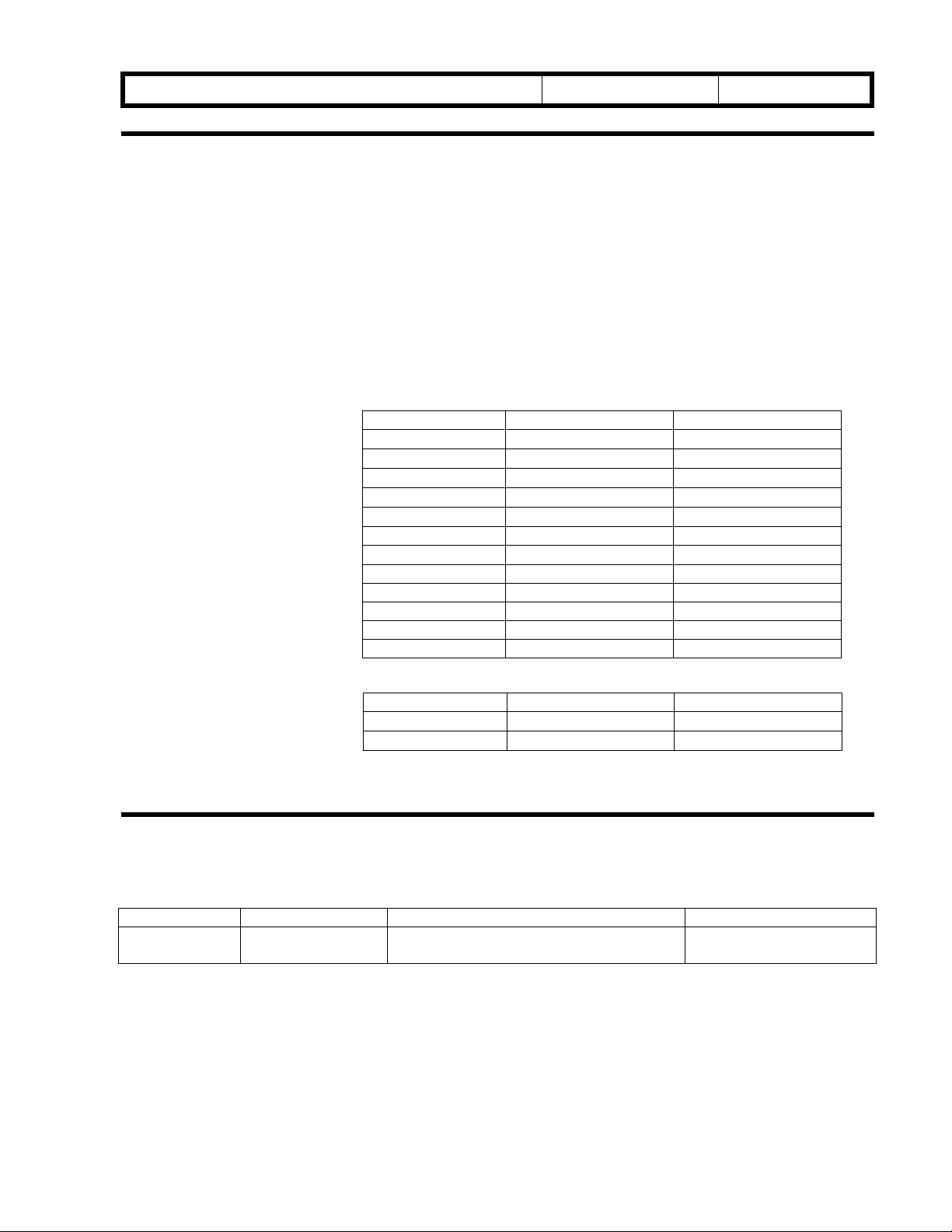
1. OVERALL MACHINE INFORMATION
1-1. SPECIFICATIONS
NOTE:
First Copy Time:
*
Warm-up Time:
Power Consumption:
*
Only items marked * are different from the base copiers.
Less than 6 seconds (A4/8.5” x 11” sideways)
NOTE:
It can be changed in SP mode.
120 V machines of A298: Less than 30 seconds (at 23 °C)
230 V machines of A298: Less than 35 seconds (at 23 °C)
*
120 V machines of A299: Less than 35 seconds (at 23 °C)
230 V machines of A299: Less than 45 seconds (at 23 °C)
A298 machines Copier only Full system
Warm up
Stand-by
Copying
Maximum
Energy saver
0.95 0.95
0.16 0.16
0.70 0.70
1.4 1.5
0.12 0.12
No.:
RA298001
Weight:
*
A299 machines
Warm up 0.95 0.95
Stand-by 0.16 0.16
Copying 0.70 0.70
Maximum 1.4 1.5
Energy saver 0.12
A298 machines
A299 machines
Copier only Full system
0.12
Copier only Full system
40.5 kg (89.3 1b) 53.5 kg (118.0 1b)
43.5 kg (95.9 1b) 56.5 kg (124.6 1b)
2. ELETRICAL COMPONENT DESCRIPTIONS
The following transformer is not included in these copiers.
Symbol Name Copier only Full system
TR Transformer Steps down the wall voltage to 30 Vac
and 8 Vac.
A219 machines: 15
A245 machines: 17
Page 3
RICOH Technical
Bulletin
PAGE: 3/4
Model:
Kingfisher 2
Date:
15-Sep-99
No.:
RA298001
3. INSATLLATION PROCEDURE
3-1. COPIER ACCESSORY CHECK
1. NECR – Multi-language (-19, -23, -27, -29, -69 machines)
2. Sheet – Operate Keytop – TWN (-19, -50 machines)
3. Sheet – Operate Keytop – CHN (-62, -69 machines)
4. Decal – Symbol Explanation – TWN (-19, 50 machines)
5. Decal – Symbol Explanation – Multi-language (-22, -23, -26, -27, 29 machines)
6. Decal – Symbol Explanation – CHN (-62, -69 mach ines)
7. Operating Instructions – Taiwanese (-19, -50 machines)
8. Operating Instructions – English (-22, -26, -29 machines)
9. Operating Instructions – Russian (-23 machines)
10. Operating Instructions – Germany (-26 machines)
11. Operating Instructions – French (-26 machines)
12. Operating Instructions – Italy (-26 machines)
13. Operating Instructions – Spanish (-26 machines)
14. Operating Instructions – Chinese (-62, -69 machines)
15. Exit Tray
16. Power Code Socket (-19, -50 machines)
17. Model Name Decal (-22, -50, -62 machines)
18. Decal – Keytop Cover (-22, -50, -62 machines)
19. Large Decal – Energy Star
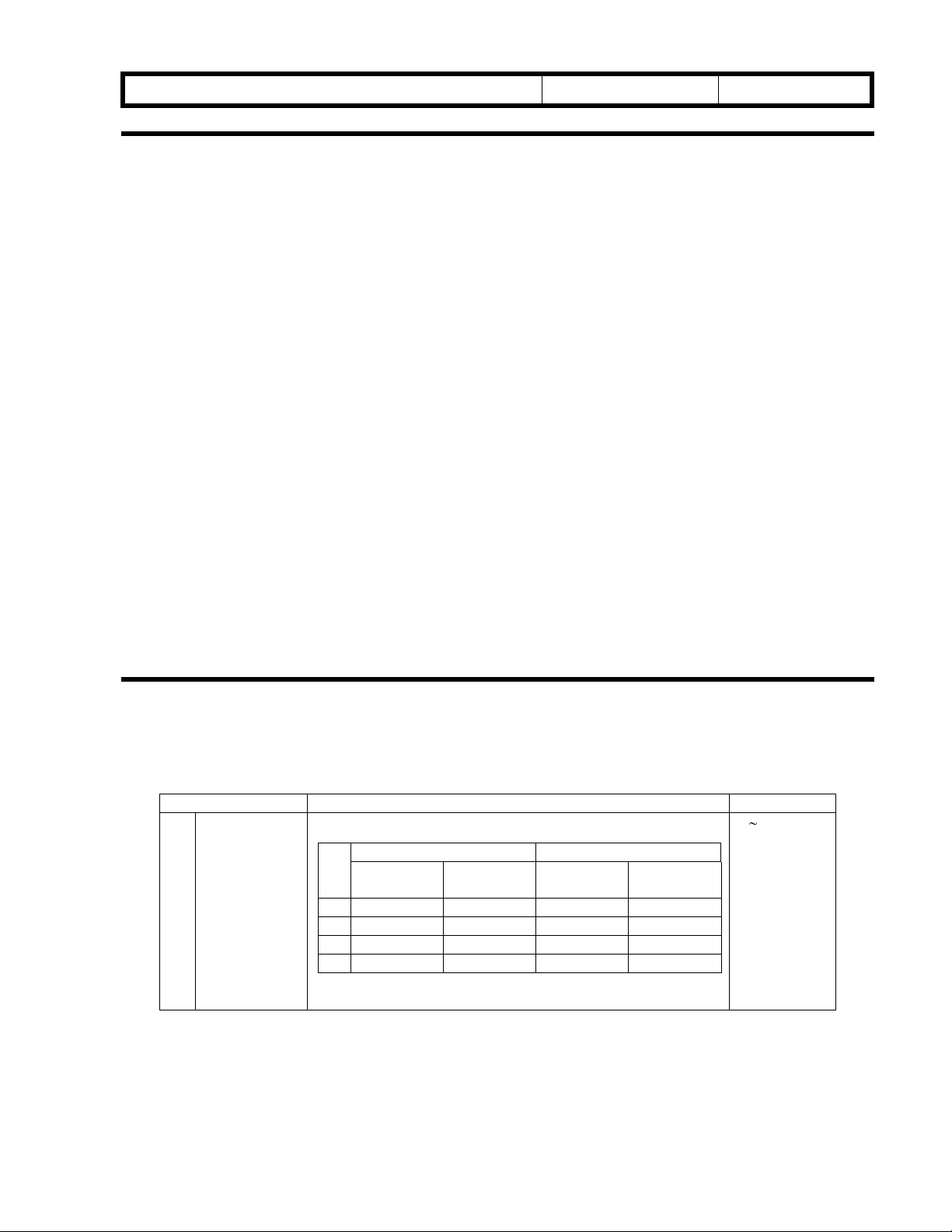
4. SERVICE TABLES
4-1. SERVICE PROGRAM MODE TABLE
The following mode was added.
Mode No. Function Settings
79 Fusing
Temperature
Setting for
Energy saver
mode
Sets the fusing temperature in energy saver mode.
A298 machines A299 machines
120V
machines
0 120 130 130 140
1 130 140 140 150
2 140 150 150 160
3 150 160 160 170
230V
machines
120V
machines
230V
machines
0 ~ 3
Default = 0
Page 4

RICOH Technical
Bulletin
PAGE: 4/4
Model:
Kingfisher 2
Date:
15-Sep-99
5. PREVENTIVE MAINTENANCE SCHEDULE
5-1. PM TABLE
All the 45K PM parts are changed to 60K.
5-2. SPECIAL TOOLS AND LUBRICANTS
The Digital Multimeter has been changed.
Part Number Description Q’ty
A0299387 Digital Multimeter 1
No.:
RA298001
Page 5

T
echnical
B
ulletin
PAGE: 1/2
Model:
Subject:
From:
Classification:
The following SP modes have been added to the KF2/GKF2.
SP 70 (No UP mode)
-User Code Mode selectionFunction: Enables User Code Mode.
Procedure:
1) Access SP mode 70.
2) Select 1:user code mode (Default is 0: No user code).
3) The machine is then ready to access the next mode number.
Note:
Cut JP101 on the main board.
Procedure to set the user code:
1) "U2" is displayed in the copy counter. Using the number keys, input the three-digit user
code number (e.g.111,123,999). Please note that 000 is invalid.
2) Press the Auto Image Density key.
3) "U2" is no longer displayed and the machine becomes ready to copy.
If any invalid values are entered or other keys are pressed, "U2" will rema in displayed
and copies cannot be made.
4) After the copy job is completed (or one minute after the last key is pressed), the
machine initiates Auto Reset and becomes ready to set the next user code. At this time,
"U2" will be displayed and copies cannot be made.
5) As an alternative, you can set the next user code by pressing the Clear Mode/Energy
Star key and then the Clear/Stop key when the machine is in Copy Ready condition.
The machine will then become ready to accept the next user code.
Kingfisher 2
User Code Mode
Technical Services Dept., GTS Division
Troubleshooting
Mechanical
Paper path
Other ( )
Part information
Electrical
Transmit/receive
Date:
31-Jan-00
Prepared by:
No.:
RA298002
M. Ishihara
Action required
Service manual revision
Retrofit information
User codes:1 - 999(*)
SP 72 (UP 12)
-Registering User Numbers-(*)
Function: Registers user numbers.
The user number (1-10) is displayed in the copy counter and code numbers are displayed
in the three digit indicator (Zoom, %).
To change the user code numbers, use the Zoom key.
Page 6

T
echnical
B
ulletin
PAGE: 2/2
Model:
Procedure:
1) Access mode number 72 in SP mode (12 for UP mode).
2) "1" is displayed in the copy counter.
A 3-digit number can be displayed in the three digit indicator (Zoom,%).
Press the Zoom Up(+) key or Zoom Down (-) key to see the ne xt user codes.
3) Enter the new user code with the number keys. This can be a 3-digit number from 1 to
999.
4) Press the Auto Image Density key. The old user code is then changed to the new code.
5)To exit from the User Tools, turn the main switch off and on.
User Numbers: User code:
1
2
. .
. .
10 1 - 999
Note: User codes are set to "0" when the machine is shipped from the factory.
Kingfisher 2
1 - 999
1 - 999
3 1 - 999
Date:
31-Jan-00
No.:
RA298002
SP 73 ( UP 8)
- User Code Counter Check Function:
Displays the copy counter value for each user number registered.
The user number (1-10) is displayed in the copy counter and the corresponding total copy
counter value is displayed in the 3-digit indicator (Zoom,%). Using the Zoom key
(up:+,down:-), you can view how many copies each registered user has made.
Procedure:
1) Access mode number 73 (number 8 for UP mode).
2) "1" is displayed in the copy counter.
3) At first, only 3 digits are displayed in the 3-digit indicator (6th, 5th and 4th).
4) After you press the "Darker" key, the next 3 digits will be displayed (3rd , 2nd and 1st).
5) To exit, press the Auto Image Density key and turn the main switch off and on.
SP 92 (UP 9)
-User Code Counter ClearFunction: Clears the total copy counter values for all registered users.
Procedure:
1) Access mode number 92 (number 9 for UP mode).
2) Press "1" on the number key pad.
3) Press the Auto Image Density key and the "Darker" key at the same time.
4) The Image density indicator will blink and begin to clear the counter values.
5) The image density indicator then turns off and all total copy counter values are
cleared. The machine will then wait for the next SP mode number to be input.
6) To exit, turn the main switch off and on.
Page 7

RICOH Technical
Bulletin
PAGE: 1/
2
Model:
Subject:
From:
Classification:
Kingfisher 2
Overtoning and toner drops on copies
Technical Services Dept., GTS Division
Troubleshooting
Mechanical
Paper path
Other ( )
Date:
Prepared by:
Part information
Electrical
Transmit/receive
29-Feb-00
Action required
Service manual revision
Retrofit information
No.:
M. Ishihara
RA298003
SYMPTOM:
1) At machine installation or after the developer is replaced, SP66 (TD sensor Initial
Setting) that would usually take about 60 seconds stops after only a few seconds.
2) After a new machine is installed, copies have high ID and/or toner drops onto copies.
This occurs until about 100 copies are made.
CAUSE:
The TD sensor connector (A1905346: Development Unit Harness) which is mounted on
the I/U (Imaging Unit) is not properly connected to the connector of the Development
Relay Board (A1905145). The board is mounted on the rear side plate of the mainframe.
If the service technician does not tighten the knob screw
raised portion of the mainframe front side plate, the TD sensor connec tor will no t be fully
inserted into the receiving connector on the board.
To check whether or not the connection is stable, make some copies and check the
reading of SP55. If the connection is unstable, the SP55 reading will also be unstable (e.g.
71,125,13,17,117,35).
pushing the I/U against the
while
Page 8

RICOH Technical
Bulletin
PAGE: 2/
2
Model:
Kingfisher 2
Date:
29-Feb-00
No.:
RA298003
SOLUTION:
I/U installation procedure
1) Insert the I/U into the mainframe.
2) Push the I/U toward the back so that the I/U front side plate(A1902280) remains flush
against the raised portion of the front side plate of the mainframe (see the illustration
below). While holding the unit in this position (pushing on the handle), tighten the knob
screw (A1902320) by hand until the I/U is secure.
Front Side Plate of the Mainframe
Front Side Plate (A1902280) of the I/U
Knob Screw (A1902320)
3) Use a slotted screwdriver or coin for the final tightening.
Page 9

T
echnical
B
ulletin
PAGE: 1/1
Model:
Subject:
From:
Classification:
The procedure for installing the imaging unit in the copier has been replaced with a more
detailed description. Please make sure to in stall the unit in this way after pouring in the
new developer at machine installation or developer replacement.
Previous:
8. Remount the cover on the imaging unit, and install the unit in the copier (1 knob screw).
Then turn the “B1” lever clockwise to raise the transfer corona unit.
Revised:
Kingfisher 2
Installation Procedure for the Imaging Unit
Technical Services Dept., GTS Division
Troubleshooting
Mechanical
Paper path
Other ( )
Part information
Electrical
Transmit/receive
Date:
10-Mar-00
Prepared by:
No.:
RA298004
M.Ishihara
Action required
Service manual revision
Retrofit information
8. Remount the cover on the imaging unit and insert the unit into the mainframe. Push
the unit toward the back until it stops. While holding the unit in this position, tighten
the knob screw by hand. For the final tightening, use a screwdriver or coin as shown in
the illustration. Then turn the B1 lever clockwise to raise the transfer corona unit.
Page 10

echnical Bulletin
T
PAGE: 1/2
Model:
Subject:
From:
Kingfisher2
Low image density in leading (top) area
Technical Services Dept., GTS Division
Classification:
Troubleshooting
Mechanical
Paper path
Other ( )
Part information
Electrical
Transmit/receive
Date:
03-Aug-00
Prepared by:
No.:
RA298005
M.Ishihara
Action required
Service manual revision
Retrofit information
SYMPTOM:
The image density of the leading (top) half of the copy becomes lighter when specific light or
halftone originals are copied.
CAUSE:
When the 1st and 2nd scanners start to move, part of the light from the 1st scanner is directly sent
to the mirror of the 2nd scanner, as the two scanners are relatively close. This "extra light" received
by the mirror will cause the image to appear lighter. As scanning continues, the 1st scanner
increases to twice the speed of the 2nd scanner, causing the two scanners to get farther and
farther apart. Therefore, less and less light "extra light" reaches the 2nd scanner mirror. This is why
the image is lighter near the leading edge.
SOLUTION:
A shading seal (A2981684) should be attached to ensure proper image density at the leading edge
(when making copies with very light/halftone originals). Because the extra light passes from the
2nd scanner mirror to the photoconductor via the base plate of the optics unit and lens carriage
(A1901682), the seal should be attached to the lower portion of the lens carriage. This will prevent
the extra light from passing between the optic base plate and lens carriage.
This modification will be applied from August 2000 production.
Please see the procedure as shown below.
Lens Carriage (A1901682)
B
A
Adhesive portion
A: 0-1mm from the edge, B: 0-0.5mm from the surface
Shading Seal (A2981684)
Page 11

echnical Bulletin
T
PAGE: 2/2
Model:
Procedure:
1. Remove the power plug from the wall outlet.
2. Remove the lens carriage from the optics unit.
Note: Before removing the lens carriage, remove the left scale, the exposure glass
and the lens cover.
3. Attach the shading seal to the lens carriage as shown in the illustration.
Kingfisher2
Date:
03-Aug-00
No.:
RA298005
Page 12

echnical Bulletin
T
PAGE: 1/2
Model:
Subject:
From:
Kingfisher2
DF Harness damage
Technical Services Dept., GTS Division
Classification:
Troubleshooting
Mechanical
Paper path
Other ( )
Part information
Electrical
Transmit/receive
Date:
28-Dec-00
Prepared by:
No.:
RA298006
M.Ishihara
Action required
Service manual revision
Retrofit information
SYMPTOM:
Damage to the harness connecting the DF44 and the copier.
CAUSE:
Sometimes, the DF is forced past its normal stop position when it is opened. If this
happens many times, the harness may be damaged.
SOLUTION:
1. User Instruction
Request the users not to force the DF past the stop position when they open it.
2. DF Bracket
A DF bracket (PN A2989500) has been registered as a service part. Place it on the
copier upper cover as shown below to prevent the DF unit from being forced too far
back.
DF
Copier Upper Cover
DF Bracket
100 ± 20mm
DF Harness
Double-sided
Tape
Page 13

echnical Bulletin
T
PAGE: 2/2
Model:
3. Upper Cover Slit
Model Code Machine serial number Applying date
A298-19 N/A N/A
-22 H2106900001 00/09/07
-23 H2106902854 00/09/04
-26 4A18900001 00/09/14
-27 H2106803121 00/08/23
-29 H2106902914 00/09/06
-50 H2107003536 00/10/27
-62 H2106903169 00/09/06
-69 H2106903269 00/09/26
Kingfisher2
A slit has been made in the upper cover to prevent the harness from being pinched
even if the DF unit is forced too far back. This change was applied from the August,
September, and October production as shown in the following table.
Date:
28-Dec-00
No.:
RA298006
Page 14

echnical Bulletin
T
PAGE: 1/1
Model:
Subject:
From:
Kingfisher2
Toner Supply Motor failure
Technical Services Dept., GTS Division
Classification:
Troubleshooting
Mechanical
Paper path
Other ( )
Part information
Electrical
Transmit/receive
Date:
10-Jan-01
Prepared by:
No.:
RA298007
M.Ishihara
Action required
Service manual revision
Retrofit information
SYMPTOM:
The toner supply motor breaks down so that the toner supply system malfunctions.
CAUSE:
The tip of the worm gear on the motor shaft wears out.
SOLUTION:
1) Apply grease to the tip and spiral threads of the present worm gear of the toner supply
motor (P/N A2983371).
Recommended grease:
Part Number Description
A1909002 Grease-CP501 (5 pcs/set)
52039502 Grease-501
- Cosmos No.1
An equivalent grease for plastic can be used instead of the above ones.
Note: Cosmos No.1 grease was applied to the tip and spiral threads of the worm gear at
the motor vendor as of July 2000 production motors onward.
2) Replace the worm gear with a new one (P/N A2983388) and apply grease to the tip and
spiral threads of the gear.
Note: The material of the new worm gear was changed to NW-02 to improve durability,
and it will be applied from the February 2001 production machines onward. We
will issue a modification bulletin (MB) to inform you of the new part number of the
toner supply motor (the motor service part includes the worm gear) and the cut-in
machine serial numbers.
Please do not order the new parts until the MB is issued, as they are not yet in
stock.
Page 15

echnical Bulletin
T
PAGE: 1/1
Model:
Subject:
From:
Kingfisher 2
SC”E14”
Technical Services Dept., GTS Division
Classification:
Troubleshooting
Mechanical
Paper path
Other ( )
Part information
Electrical
Transmit/receive
Date:
12-Apr-01
Prepared by:
SYMPTOM:
SC ”E14” (220-240V region).
CAUSE:
-The power input (voltage and/or frequency) is out of standard, or
-Electrical noise interferes with the power input.
SOLUTION:
There are two solutions:
No.:
RA298008
M.Ishihara
Action required
Service manual revision
Retrofit information
1) Use a power source where the actual power input is within machine standards:
220-240V,50/60Hz +, - 10%.
2) Use the following PSU (Power Supply Unit) that has been arranged for specific
customers and contains a countermeasure for SC ”E14”:
Part Number Description
A2989501 Power Supply Unit-230V
*Modification: This is the A2985651 PSU with a 0.01µF capacitor soldered (added) to its
rear face.
Page 16

!"#$% T
echnical Bulletin
PAGE: 1/1
Model:
Subject:
From:
Kingfisher 2
SC Code E-90
Technical Services Dept., GTS Division
Classification:
Troubleshooting
Mechanical
Paper path
Other ( )
Part information
Electrical
Transmit/receive
Date:
14-Nov-01
Prepared by:
No.:
RA298009
M. Ishihara
Action required
Service manual revision
Retrofit information
Please add the following SC description to the Service Call Conditions in the Service
Manual.
SC Code E-90 (Exposure Lamp Off)
Definition
Detects that the exposure lamp is off at 50 mm from the edge of the original.
Possible causes
Exposure lamp control system failure.
! Connectors not connected properly
! Exposure lamp failure
! Lamp regulator failure
! Main board failure
! PSU failure (AC/DC Power Supply Unit)
Remedy
Check the above causes, then turn the main switch off and on.
 Loading...