

Page 1
RICOH Technical
Bulletin
PAGE: 1/4
Model:
Subject:
From:
Tequila
Toner drops onto the copy
Technical Service Dept., GTS Division
Classification:
Troubleshooting
Mechanical
Paper path
Other ( )
Date:
Prepared by:
Part information
Electrical
Transmit/receive
22-Sep-99
Action required
Service manual revision
Retrofit information
No.:
M. Ishihara
RA289001
SYMPTOM
1. Toner drops onto the copy.
2. Dirty background on copies (Occasional)
3. Image density too high (Occasional)
CAUSE
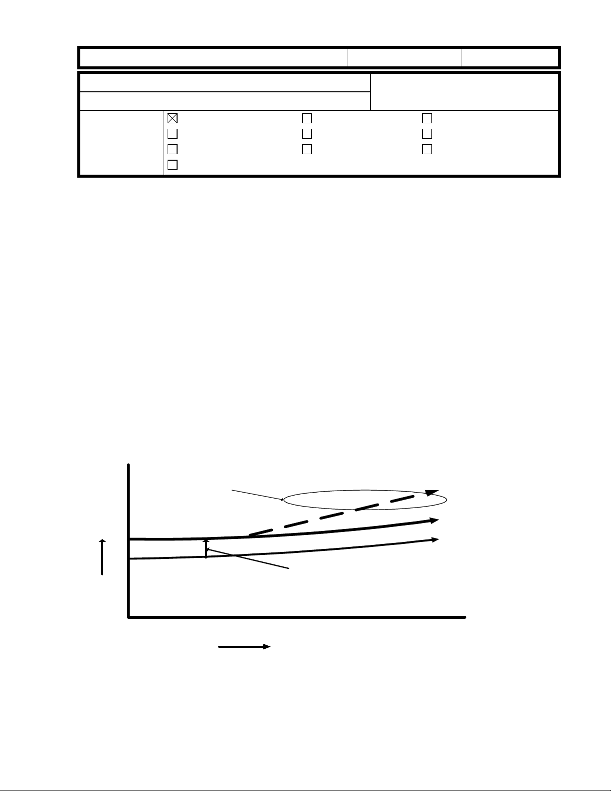
Although the toner concentration in the developer is maintained between 3 and 4%,
an increase can be observed when used over an extended period of time. This level
is normally kept under 5% even after 60K copies, however there are rare cases where this
limit is exceeded due to the environmental factors described below. These are thought to
cause the toner to fall onto the surface of the copy.
1. The presence of paper dust as well as conditions such as high humidity are thought to
cause an oversupply of toner to the development unit (by raising the limit of the toner
concentration control to over 6%), which in turn causes the toner to fall onto the copy
surface.
Too much toner
4%
3%
Controlled Limit
Toner
Consent
-ration
0 20K 60K40K
Copy Volume
6%
5%
4%
2. In addition, due to this oversupply of toner to the development unit, recycled toner
creates a blockage in the imaging unit and the toner falls from the cleaning area.
Page 2
RICOH Technical
Bulletin
PAGE: 2/4
Model:
Tequila
Date:
22-Sep-99
No.:
RA289001
ACTION REQUIRED
A. Countermeasure in the field:
Please follow the procedure as shown below if the toner dropping problem occurs in the
field.
1. Remove the IU from the machine.
2. Completely remove the recycled toner at the toner collection coil under the cleaning
blade and the toner recycling belt area. Install the IU in the machine.
3. Remove the toner bottle from the machine. Check that SP38 is 0. (Input "0" if it is not.)
4. Make 20, A4 sideways, skyshot copies (Black solid copies).
5. Set an original and make some copies to confirm that copy quality is normal.
6. Change the toner supply mode from “0” to “1” using SP30.
7. Make some copies while monitoring the TD sensor output (SP55).
8. Input the value obtained in step 7 into SP53 – TD Sensor Target Control Voltage
Adjustment. (If it is more than 127, input 127.)
9. Install the toner bottle in the machine.
10.Set an original and make some copies to confirm that copy quality is normal.
Note:
When the developer is replaced, please observe the following for efficient troubleshooting:
1) Perform the SP66 to initialize the developer .
2) Do not change the settings of SP30 and SP53. (SP30 must be at “1”. TD Sensor
control voltage must be kept at the same level in SP53, as entered in step 8 above.)
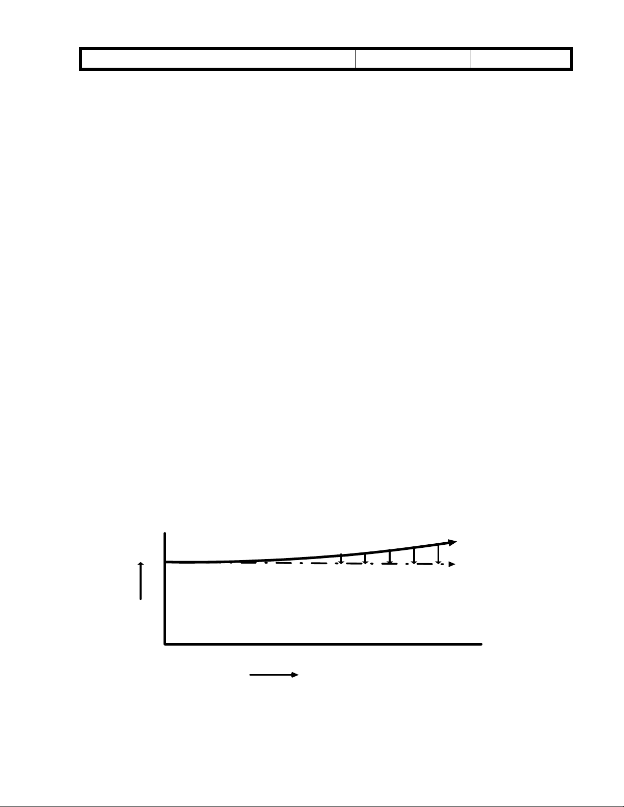
B. Permanent Countermeasure:
This rise in the amount of tone r being supplied will be prevented as de termined by the
copy volume by modifying the software so that an oversupply does not result.
For the
machine of mass production. It is scheduled to be implemented in the
October 1999 mass production.
Kingfisher2
4%
Toner
Density
, this modification is scheduled to be implemented from the first
Kingfisher
5%
4%
0 20K 60K40K
from
Page 3

RICOH Technical
Bulletin
PAGE: 3/4
Model:
If the above symptom should occur in the field before preventative maintenance is
performed, please institute the temporary countermeasure described in the previous
section (A.) and refrain from upgrading the software.
The new software has two major differences from the previous version:
The overall process control and toner density control (maintained by lowering
it to a fixed value every 1K). Due to these differences, it is recommended that
the new firmware be used together with new developer.
NOTE:
Please upgrade the software at the next PM visit (when the developer is replaced).
Please refer to the flow chart on the following page.
(Note: When the developer is replaced, remove the old developer completely. Otherwise
the volume of the developer is increased and it causes the toner to drop.)
Tequila
Date:
22-Sep-99
No.:
RA289001
Page 4
RICOH Technical
Bulletin
PAGE: 4/4
Model:
Tequila
Date:
22-Sep-99
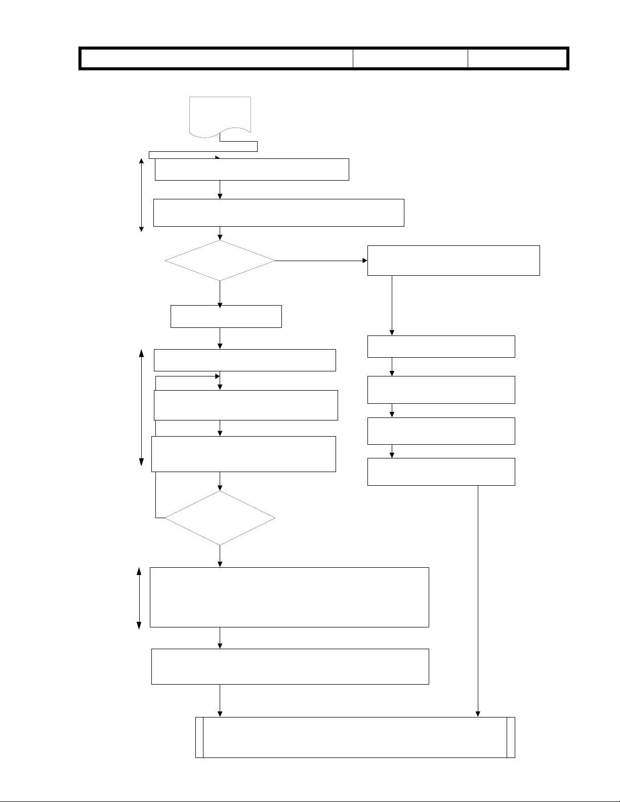
FLOW CHART FOR THE TONER DROPPING PROBLEM
START
Remove the Imaging Unit from the machine.
Remove the recycled toner in cleaning unit
(under the cleaning blade) and at the recycling belt area.
YES
To remove
excessive
toner from the
developing unit
Is PM required?
NO
Install the imaging Unit.
Remove the toner bottle from the machine.
Input "0" in SP38 if it is not.
Make 20(A4 sideways) skyshot copies to
confirm that copy quality is normal.
Set an original and make some copies to
confirm that the copy quality is normal.
Replace the developer in the imaging Unit.
Note: Completely remove the developer
from the imaging unit.
(Otherwise the amout of developer will
increase causing toner recycling process
not function properly.
Install the imaging Unit.
Replace the ROM.
Perform the toner initialization
(SP66).
If the SP30 is "1", set it to "0".
No.:
RA289001
To maintain
proper toner
density
NO
Change the toner supply mode from "0" to "1" (in the SP30).
Make several copies while monitoring the TD sensor output (SP55).
Input the value obtained in the previous step into SP53 - TD Sensor
Target Control VoltageAdjustment.
Install the toner bottle in the machine.
Set an original and make several copies to confirm that copy quality
is normal.
Is Image density
normal?
YES
END!
Page 5

T
echnical
B
ulletin
PAGE: 1/2
Model:
Subject:
From:
Classification:
The troubleshooting procedures for this problem have been outlined in previous RTBs.
The software for the following ROMs have been modified:
Model: ROM P/N: Suffix:
Kingfisher A2195104 G
Grand Kingfisher A2455104 D
Tequila A2895104 D
Modifications:
Tequila
Overtoning / black spots on copies
Technical Services Dept., GTS Division
Troubleshooting
Mechanical
Paper path
Other ( )
Part information
Electrical
Transmit/receive
Date:
31-Jan-00
Prepared by:
No.:
RA289002
M. Ishihara
Action required
Service manual revision
Retrofit information
1. The method for calculating the target TD sensor output (Target VT) has been changed.
The previous Target VT will be called “VTref”, and its default value has been changed
from 1.9 to 1.5V. The alpha and beta corrections described below will be added to
VTref. The new Target VT is then calculated as:
Target VT = VTref + α + β
2. For toner density correction, SP37 (alpha correction) has been added as a new
SP Mode. In addition, items 5 and 6 in the second table below have been added to SP38
(beta correction).
Alpha Correction:
This correction is designed to operate gradually, over a period of time. Therefore,
it should not be used to achieve quick results.
SP37 Correction Level: Variable Correction Target:
0 No correction
1 +0.06V / 1K copies
2 +0.04V / 1K copies
- -
-
Lighter
Light
3 +0.02V / 1K copies Default
4 +0.02V / 2K copies
5 +0.02V / 4K copies
+
++
Dark
Darker
Page 6

T
echnical
B
ulletin
PAGE: 2/2
Model:
Beta Correction:
Please note that items 5 and 6 have been newly added to SP38.
SP38
0 No correction
1 Darker +0.5% -0.375V
2 Lighter -0.5% +0.375V
3 Dark +1.0% -0.75V
4 Light -1.0% +0.75V
5 Darkest +1.3% -1.0V
6 Lightest -1.3% +1.0V
Tequila
Target Toner Density
Date:
Correction Target:
31-Jan-00
No.:
Target VT
Correction:
RA289002
Limitations:
-The maximum absolute value of the combined alpha and beta corrections is 1V.
Therefore:
-When SP66 is performed, the correction counter resets.
+ β ≤ 1.
α
Page 7

!"#$% T
echnical Bulletin
PAGE: 1/2
Model:
Subject:
From:
Tequila
Overtoning and toner dropping onto copies
Technical Services Dept., GTS Division
Classification:
Troubleshooting
Mechanical
Paper path
Other ( )
Part information
Electrical
Transmit/receive
Date:
19-Apr-00
Prepared by:
No.:
RA289003
M. Kitajima
Action required
Service manual revision
Retrofit information
SYMPTOM:
1) At machine installation or after the developer is replaced, SP66 (TD sensor Initial
Setting) that would usually take approximately 60 seconds stops after only a few
seconds.
2) After a new machine is installed, copies have high ID and/or toner drops onto copies.
This occurs until approximately 100 copies are made.
CAUSE:
The TD sensor connector (A1905346: Development Unit Harness) which is mounted on
the I/U (Imaging Unit) is not properly connected to the connector of the Development
Relay Board (A1905145). The board is mounted on the rear side plate of the mainframe.
If the service technician does not tighten the knob screw while pushing the I/U against the
raised portion of the mainframe front side plate, the TD sensor connector will not be fully
inserted into the receiving connector on the board.
To check whether or not the connection is stable, make some copies and check the
reading of SP55. If the connection is unstable, the SP55 reading will also be unstable (e.g.
71,125,13,17,117,35).
Page 8

!"#$% T
echnical Bulletin
PAGE: 2/2
Model:
Tequila
Date:
19-Apr-00
No.:
RA289003
SOLUTION:
I/U installation procedure
1) Insert the I/U into the mainframe.
2) Push the I/U toward the back so that the I/U front side plate (A1902280) remains flush
against the raised portion of the front side plate of the mainframe (see the illustration
below). While holding the unit in this position (pushing on the handle), tighten the knob
screw (A1902320) by hand until the I/U is secure.
Front Side Plate of the Mainframe
Front Side Plate (A1902280) of the I/U
Knob Screw (A1902320)
3) Use a slotted screwdriver or coin for the final tightening.
Page 9

echnical Bulletin
T
PAGE: 1/2
Model:
Subject:
From:
Tequila
Low image density in leading (top) area
Technical Services Dept., GTS Division
Classification:
Troubleshooting
Mechanical
Paper path
Other ( )
Part information
Electrical
Transmit/receive
Date:
03-Aug-00
Prepared by:
No.:
RA289004
M.Ishihara
Action required
Service manual revision
Retrofit information
SYMPTOM:
The image density of the leading (top) half of the copy becomes lighter when specific light or
halftone originals are copied.
CAUSE:
When the 1st and 2nd scanners start to move, part of the light from the 1st scanner is directly sent
to the mirror of the 2nd scanner, as the two scanners are relatively close. This "extra light" received
by the mirror will cause the image to appear lighter. As scanning continues, the 1st scanner
increases to twice the speed of the 2nd scanner, causing the two scanners to get farther and
farther apart. Therefore, less and less light "extra light" reaches the 2nd scanner mirror. This is why
the image is lighter near the leading edge.
SOLUTION:
A shading seal (A2981684) should be attached to ensure proper image density at the leading edge
(when making copies with very light/halftone originals). Because the extra light passes from the
2nd scanner mirror to the photoconductor via the base plate of the optics unit and lens carriage
(A1901682), the seal should be attached to the lower portion of the lens carriage. This will prevent
the extra light from passing between the optic base plate and lens carriage.
This modification will be applied from August 2000 production.
Please see the procedure as shown below.
Lens Carriage (A1901682)
B
A
Adhesive portion
A: 0-1mm from the edge, B: 0-0.5mm from the surface
Shading Seal (A2981684)
Page 10

echnical Bulletin
T
PAGE: 2/2
Model:
Procedure:
1. Remove the power plug from the wall outlet.
2. Remove the lens carriage from the optics unit.
Note: Before removing the lens carriage, remove the left scale, the exposure glass
and the lens cover.
3. Attach the shading seal to the lens carriage as shown in the illustration.
Tequila
Date:
03-Aug-00
No.:
RA289004
Page 11

echnical Bulletin
T
PAGE: 1/1
Model:
Subject:
From:
Tequila
SC ”E14”
Technical Services Dept., GTS Division
Classification:
Troubleshooting
Mechanical
Paper path
Other ( )
Part information
Electrical
Transmit/receive
Date:
12-Apr-01
Prepared by:
No.:
RA289005
M.Ishihara
Action required
Service manual revision
Retrofit information
SYMPTOM:
SC ”E14” (220-240V region).
CAUSE:
-The power input (voltage and/or frequency) is out of standard, or
-Electrical noise interferes with the power input.
SOLUTION:
There are two solutions:
1) Use a power source where the actual power input is within machine standards:
220-240V,50/60Hz +, - 10%.
2) Use the following PSU (Power Supply Unit) that has been arranged for specific
customers and contains a countermeasure for SC ”E14”:
Part Number Description
A2989501 Power Supply Unit-230V
*Modification: This is the A2985651 PSU with a 0.01µF capacitor soldered (added) to its
rear face.
 Loading...