

Page 1

IMPORTANT SAFETY NOTICES
PREVENTION OF PHYSICAL INJURY
1. Before disassembling or assembling parts of the copier and peripherals,
make sure that the copier power cord is unplugged.
2. The wall outlet should be near the copier and easily accessible.
3. Note that the optional tray heater and the optional anti-condensation
heaters are supplied with electrical voltage even if the main switch is
turned off.
4. If any adjustment or operation check has to be made with exterior
covers off or open while the main switch is turned on, keep hands away
from electrified or mechanically driven components.
5. The inside and the metal parts of the fusing unit become extremely hot
while the copier is operating. Be careful to avoid touching those
components with your bare hands.
HEALTH SAFETY CONDITIONS
1. Toner and developer are non-toxic, but if you get either of them in your
eyes by accident, it may cause temporary eye discomfort. Try to remove
with eye drops or flush with water as first aid. If unsuccessful, get
medical attention.
OBSERVANCE OF ELECTRICAL SAFETY STANDARDS
1. The copier and its peripherals must be installed and maintained by a
customer service representative who has completed the training course
on those models.
SAFETY AND ECOLOGICAL NOTES FOR DISPOSAL
1. Do not incinerate toner cartridges or used toner. Toner dust may ignite
suddenly when exposed to open flame.
2. Dispose of used toner, developer, and organic photoconductors in
accordance with local regulations. (These are non-toxic supplies.)
3. Dispose of replaced parts in accordance with local regulations.
Page 2

Grand Kingfisher
(Machine Code:A245)
Service Manual
–
Insert Version
–
The A245 copier is based on the A219 copier.
Only the differences from the A219 copier are described in the
following pages. Refer to the A219 copier service manual
regarding the other information.
Page 3

26 September 1997 SPECIFICATIONS
1. SPECIFICATIONS
NOTE:
Only items marked with ✽ are different from the A219 copier.
Configuration: Desktop
Copy Process: Dry electrostatic transfer system
Originals: Sheet/Book
Original Size: Maximum: A3/11" x 17"
Copy Paper Size: Maximum: A3/11" x 17"
Minimum:
A5/5
A6/5
1/2
1/2
" x 8
" x 8
1/2
" sideways (Paper tray feed)
1/2
" lengthwise (By-pass feed)
Non-standard sizes:
Vertical 45 mm ~ 308 mm, 1.8" ~ 12"
Horizontal 148 mm ~ 432 mm, 5.8" ~ 17"
2
Copy Paper Weight: Paper tray feed: 64 to 90 g/m
By-pass feed: 52 to 157 g/m
Reproduction Ratios:
Enlargement
Full Size 100% 100%
Reduction
Metric Version Inch Version
200%
141%
122%
93%
82%
71%
50%
, 17 to 24 lb
2
, 14 to 42 lb
Copier
200%
155%
129%
93%
74%
65%
50%
Zoom: From 50% to 200% in 1% steps
✽ Copying Speed: 18 copies/minute (A4/8.5" x 11" sideways)
10 copies/minute (A3/11" x 17")
✽ Warm-up Time:
120 V machines: Less than 35 seconds (at 23°C)
230 V machines: Less than 45 seconds (at 23°C)
✽ First Copy Time: Less than 6.5 seconds (A4/8.5" x 11" sideways)
Copy Number Input: Number keys, 1 to 99
Manual Image Density
7 steps
Selection:
1
Page 4

SPECIFICATIONS 26 September 1997
Automatic Reset: 1 minute standard setting; can also be set to 3
minutes or no auto reset
✽ Paper Capacity: Paper tray: 250 sheets or less than 30 mm stack
height
By-pass feed entrance:
Standard paper 80 sheets
OHP 10 sheets
Others 1 sheet
Toner Replenishment: Bottle exchange (215 g/bottle)
Copy Tray Capacity: 100 sheets
Power Source: 120 V/60 Hz: More than 15 A (for North America)
220 ~ 240 V/50 Hz: More than 8 A (for Europe)
220 V/50 Hz: More than 8 A (for Asia)
220 V/60 Hz: More than 8 A (for Middle East/Asia)
110 V/60 Hz: More than 15 A (for Taiwan)
127 V/60 Hz: More than 15 A (for Middle East)
✽ Power Consumption:
✽ Dimensions:
Copier only Full system*
1.4 kW
Maximum
Copy cycle 0.82 kW 0.85 kW
Warm-up 0.95 kW 0.95 kW
Stand-by 0.16 kW 0.16 kW
Energy saver 0.12 kW 0.12 kW
*Full system : Copier with document feeder and 10 - bi n sorter
Copier
Full system*
*Full system : Co pi er w i th d ocument feeder an d 10- bi n sorter
(120 V machines)
1.1 kW
(230 V machines)
Width Depth Height
579 mm
(22.8")
775 mm
(30.2")
560 mm
(22.1")
560 mm
(22.1")
1.5 kW
(120 V machines)
1.2 kW
(230 V machines)
465 mm
(183.8")
563 mm
(21.5")
2
Page 5

26 September 1997 SPECIFICATIONS
✽ Noise Emissions: Sound pressure level (the measurements are
made in accordance with ISO 7779 at the
operator position.)
✽ Weight:
Optional Equipment:
(Sales items)
Optional Equipment:
(Service items)
Copier only Full system*
Copyin g 58 dB or less 62 dB or less
*Full system : Co pi er w i th d ocument feeder an d 10- bi n sorter
Sound power level (the measurements are made
in accordance with ISO 7779)
Copier only Full system*
Stand- by 40 dB or less 40 dB or less
Copy cycl e 64 dB or less 68 dB or le ss
*Full system : Co pi er w i th d ocument feeder an d 10- bi n sorter
Copier only
Full system *
*Full system : Co pi er w i th d ocument feeder an d 10- bi n sorter
45 kg (99.2 lb)
58 kg (128 lb)
Document feeder (A662)
10-bin sorter (A657)
Optics anti-condensation heater
Tray heater
Copier
•
Specifications are subject to change without
notice.
3
Page 6
MECHANICAL CO M PO N EN T LAYO U T 26 September 1997
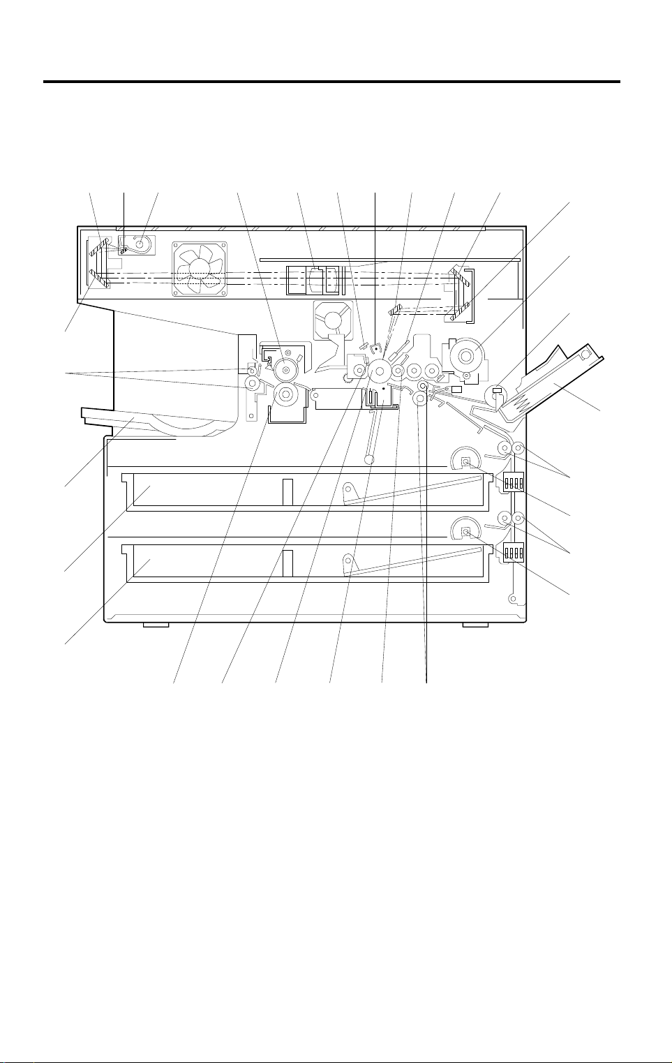
2. MECHANICAL COMPONENT LAYOUT
NOTE:
29
28
27
The paper feed area has been changed.
7
10
98654321
11
12
13
14
15
16
26
25
24
1. 2nd Mirror
2. 1st Mirror
3. Exposure Lamp
4. Hot Roller
5. Lens
6. Quenching Lamp
7. Charge Corona Unit
8. 6th Mirror
9. Erase Lamp
10. 4th Mi r r or
23 22 1920
11. 5th Mi r r or
12. Toner Bottle Holder
13. By-pass Feed Roller
14. By-pass Feed Table
15. Upper Relay Rollers
16. Upper Tray Pap er F eed
Rollers
17. Lower Relay Rollers
18. Lower Tray Paper Feed
Rollers
19. Registration Rollers
21
17
18
A245V500.wmf
20. Development Roller
21. Transfer/Separation Unit
22. Drum
23. Cleaning Bl ade
24. Pressure Roller
25. Lower Paper Tray
26. Upper Paper Tray
27. Copy Tray
28. Exit Rollers
29. 3rd Mi r ror
4
Page 7
26 September 1997 DRIVE LAYOUT
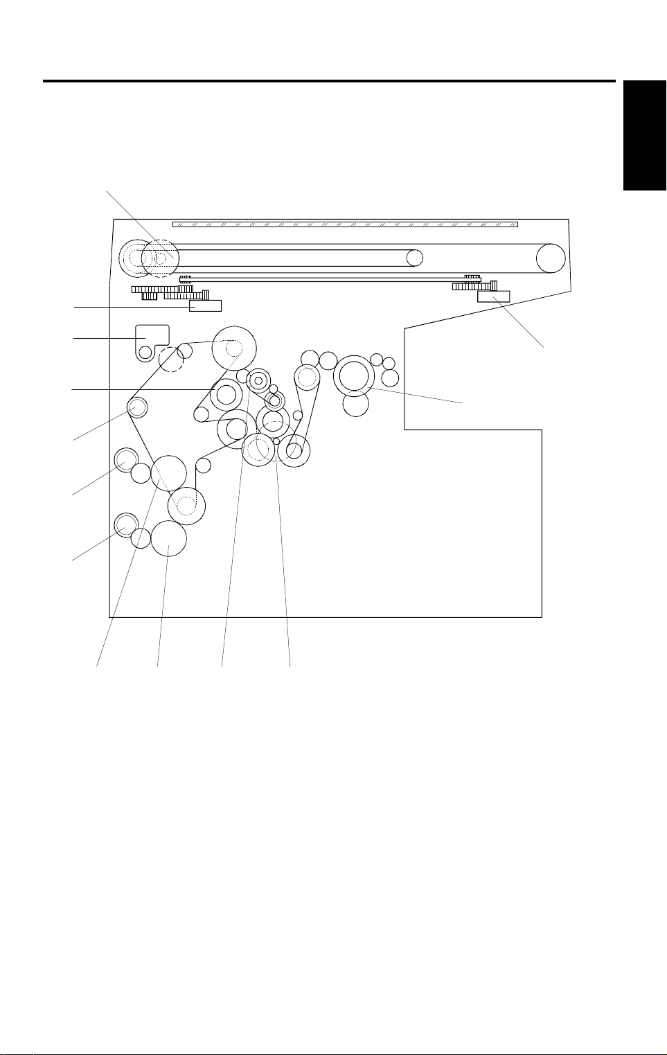
3. DRIVE LAYOUT
NOTE:
12
11
10
9
8
The paper feed area has been changed.
Copier
13
1
2
7
6
1. Lens Motor
2. Fusing Unit Drive Gear
3. Main Motor
4. Drum Drive Gear
5. Lower Tray Paper Feed Clutch Gear
6. Upper Tray Paper Feed Clutch Gear
7. Lower Relay Roller Clutch Gear
54 3
A245V501.wmf
8. Upper Relay Roller Clutch Gear
9. By-pass Paper Feed Clut ch
10. Registration Clutch Gear
11. Toner Supply Motor
12. 4th/5th Mirror Motor
13. Scanner Drive Motor
5
Page 8
PAPER PATH 26 September 1997
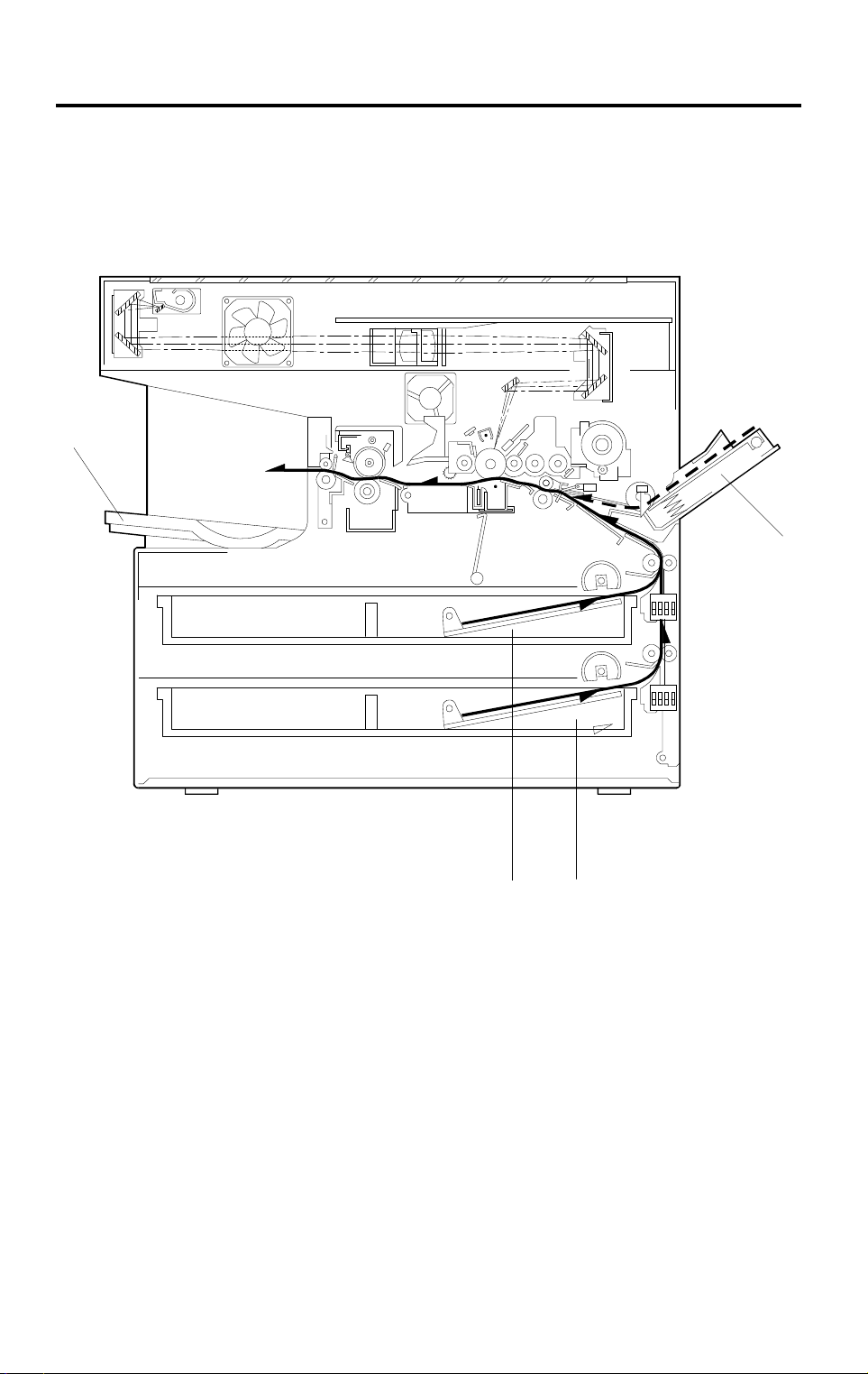
4. PAPER PATH
NOTE:
4
The paper feed area has been changed.
1
1. By-pass Feed
2. Lower Paper Tray Feed
3. Upper Paper Tray Feed
4. Copy Tray
3
6
2
A245V502.wmf
Page 9
26 September 1997 ELECTRICAL COMPONENT DESCRIPTIONS
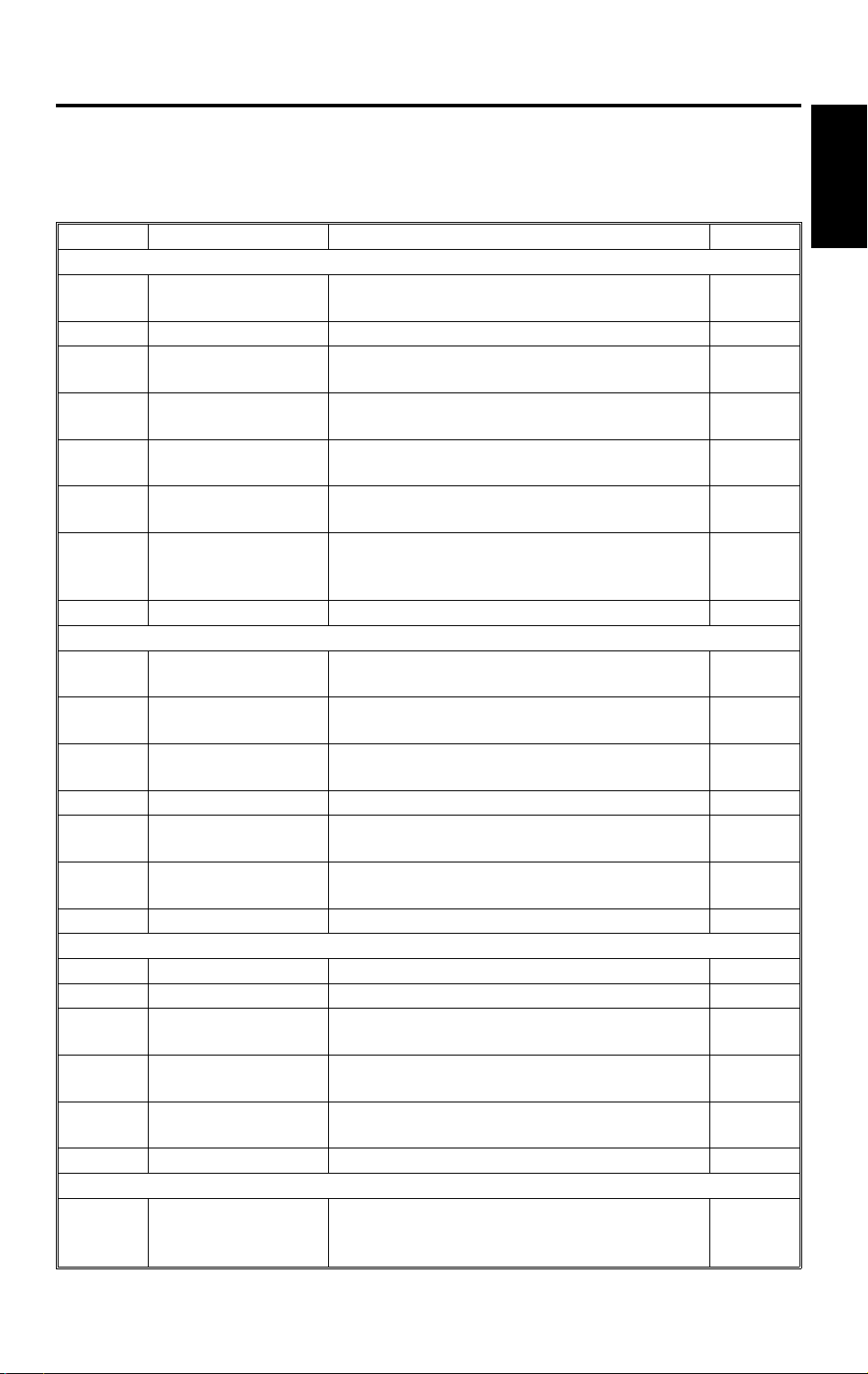
5. ELECTRICAL COMPONENT DESCRIPTIONS
Refer to the electrical component layout and the point-to-point diagram on the
waterproof paper in the pocket for symbols and index numbers.
Symbol Name Function Index No.
Motors
M1
M2 Scanner Drive M ot or Dri ves the scanners (1s t and 2nd). 9
M3
M4
M5
M6
M7
Main Motor Drives all th e m ai n unit component s except for
the optics un i t an d fa ns.
Lens Motor Moves the lens position in accor dance with
the selecte d m agnification.
4th/5th Mirror Motor Moves the 4th/5th mirror position in
accordanc e w ith the selected magnification.
Toner Supply M ot or Rotates the to ner bot tle to supply toner to the
development uni t .
Optics Cooling Fan
Motor
Exhaust Fan Mot or Removes heat from a ro und the fusing unit and
Prevents buil d- up of hot air in the opti cs cavity.
blows the ozone built up around the charge
corona unit towards the ozone filter.
8
20
18
10
19
7
Copier
Clutches
CL1
CL2
CL3
CL4 Registration Clutch Drives the registration rollers. 11
CL5
CL6
Switches
SW1 Main Swit ch Supplies power to the copier. 43
SW2 Interlock Switch Cuts all power when the front cover is opened. 42
SW3
SW4
SW5
Upper Tray Paper
Feed Clutch
By-pass Paper F eed
Clutch
Lower Tray Paper
Feed Clutch
Upper Relay Roller
Clutch
Lower Relay Roller
Clutch
Upper Tray Paper
Size Switch
Right Vertical Guide
Switch
Lower Tray Paper
Size Switch
Transfers ma in motor drive to the upper paper
feed roller.
Starts paper fee d fr om t he by-pass feed tabl e.
Transfers ma in motor drive to the l ow er paper
feed roller.
Drives the upp er relay rollers for upper paper
tray feed.
Drives the lower relay rollers for lower paper
tray feed.
Determin es w hat size of paper is in t he upper
paper tray.
Cuts the +24 V dc power line of the relay roller
clutch.
Determines what size of paper is in the lower
paper tray.
13
12
16
14
15
36
30
35
Sensors
S1
4th/5th Mirro r Hom e
Position Sensor
Informs the CPU when the 4th/5th mirror
assembly is at the home position (full size
position).
7
28
Page 10

ELECTRICAL COMPONENT DESCRIPTIONS 26 September 199 7
Symbol Name Function Index No.
S2 ADS Sensor Detects the background density of th e or i gi nal. 26
S3
Upper Tray Paper
End Sensor
Informs the CPU w hen the upper paper tr ay
runs out of pape r.
31
Registratio n Sensor Detects the leading edge of th e copy paper to
S4
determine t he st op timing of the rela y roller
34
clutch, and det e ct s m i sf eeds.
S5
By-pass Feed Paper
End Sensor
Informs the CPU w hen there is no paper in the
by-pass tray .
33
S6 Exit Sensor Detects misfeeds. 25
S7
S8
S9
S10
Scanner Home
Position Sensor
Lens Home Posit ion
Sensor
Toner Density (TD)
Sensor
Lower Tray Paper
End Sensor
Informs the CPU w hen the 1st scanner i s at
the home position.
Informs the CPU w hen the lens is at the hom e
position.
Detec ts the ra tio of ton er to car rier in th e
developer.
Informs the CPU when the lower paper tray
runs out of pape r.
45
24
29
32
Printed Circuit Boards
PCB1 Main Control Boar d Controls all copier functions. 1
PCB2
High Voltage Supply
Board - C/G/B/T/S
Provides high voltage to the charge corona,
grid, development bias, transfer corona, and
2
discharge plate.
PCB3
AC Drive/DC Power
Supply Board
Drives the exp o sure lamp, fusing l amp, and
main motor. Rectifies 30 Vac and 8 Vac input
3
and outputs 5 Vdc and 24 Vdc.
PCB4
Operation Pane l
Board
Informs the CPU of the selected mode s and
displays the si t uation on the panel.
6
Lamps
Erase Lamp Discharges the dr um outside of the image
L1
area. (Provides leading/trailing edge and side
erases.)
L2
L3
Quenching Lamp Neutralizes any char ge r em a ining on the drum
surface after cl eaning.
Exposure Lamp Applies high intensity light to the original for
exposure.
L4 Fusing Lamp Provides hea t to the hot r oller. 27
Others
CO1
H1
H2
Total Counter Keeps track o f the t ot al num ber of copies
made.
Upper Tray Heat er
(Option)
Optics
Anti-condensat i on
Heater (Opti on)
Turns on when t he main switch is of f to keep
paper in the up per paper tray dry.
Turns on when t he main switch is of f to
prevent moisture from accumulating in the
optics.
8
4
5
22
39
38
44
Page 11

26 September 1997 ELECTRICAL COMPONENT DESCRIPTIONS
Symbol Name Function Index No.
H3
TF1
TF2
TH1
TH2
TR
Lower Tray Heat er
(Option)
Exposure Lamp
Thermofuse
Fusing Therm of u se Provide back-up overheat protection in the
Fusing Therm i st or M onitors the tem per ature around the ex posure
Optics Therm i st or Monitors th e te mperature around t he exposure
Transformer Steps down the wall vol t age to 30 Vac and 8
Turns on when t he main switch is of f to keep
paper in the lower paper tray dry .
Provide back-up overheat protection around
the exposure lamp.
fusing unit.
lamp for over heat protection.
lamp for over heat protection.
Vac.
37
23
41
40
21
17
Copier
9
Page 12
PAPER FEED 26 September 1997
6. PAPER FEED
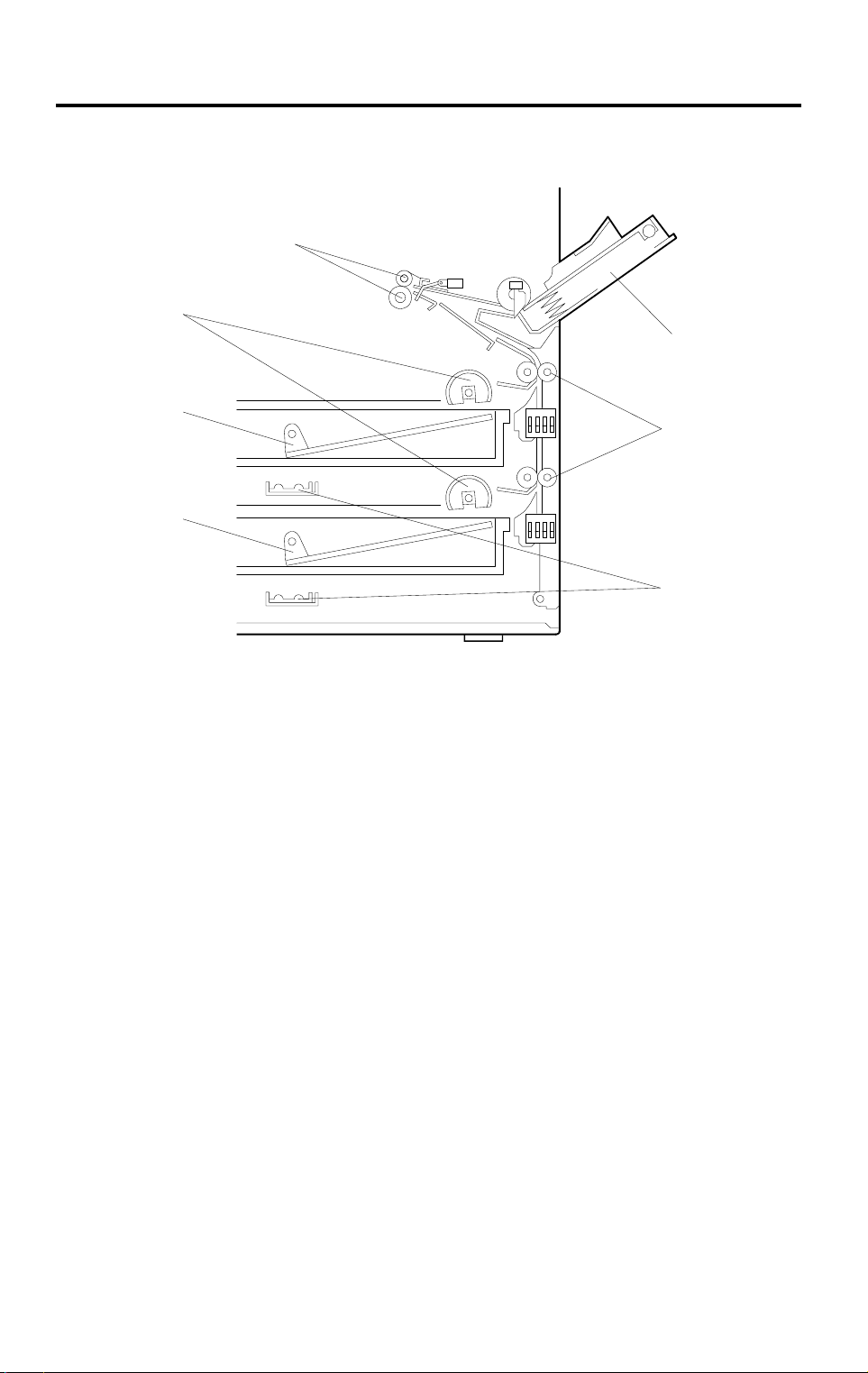
6.1 OVERVIEW
[E]
[D]
[A]
[B]
[F]
[C]
[G]
A245D500.wmf
There are two paper trays and a by-pass feed table [A].
The upper [B] and lower [C] paper trays each hold 250 sheets. The by-pass
feed table can hold 1, 10, or 80 sheets of paper, depending on the paper type.
The semicircular feed rollers [D] drive the top sheet of paper from the tray to
the registration rollers [E] through the relay rollers [F].
The tray has two corner separators (see [F] in the diagram in the "Paper Lift
Mechanism" section), which allow only one sheet to feed at a time. The
corner separators, along with the tray’s springs, also serve to set the height
of the paper stack.
When the tray is closed after the paper is loaded, the paper size actuator
located at the front right of the tray pushes the paper size sensor. This
informs the cpu what paper size is loaded in the tray and that the tray is in
place.
The by-pass feed table uses a feed roller and friction pad system to feed the
top sheet of paper to the registration rollers.
In humid environments, copy paper may crease as it comes out of the fusing
unit. The optional tray heaters [G] are available as service parts to keep copy
paper dry. It can be installed for both paper trays.
10
Page 13

26 September 1997 PAPER FEED
6.2 PAPER LIFT MECHANISM
[F]
[D]
[E]
[A]
[C]
[B]
[F]
A245D501.wmf
When the paper tray [A] is closed after paper is loaded, the release slider [B],
which is mounted on the bottom part of the tray, is pushed by the projection
[C] on the main frame and the release slider comes off the bottom plate hook
[D].
Copier
Once the release slider comes off, the bottom plate is raised by the pressure
springs [E] and the top sheet pushes up the corner separators [F]. This keeps
the stack of paper at the correct height.
11
Page 14
PAPER FEED 26 September 1997
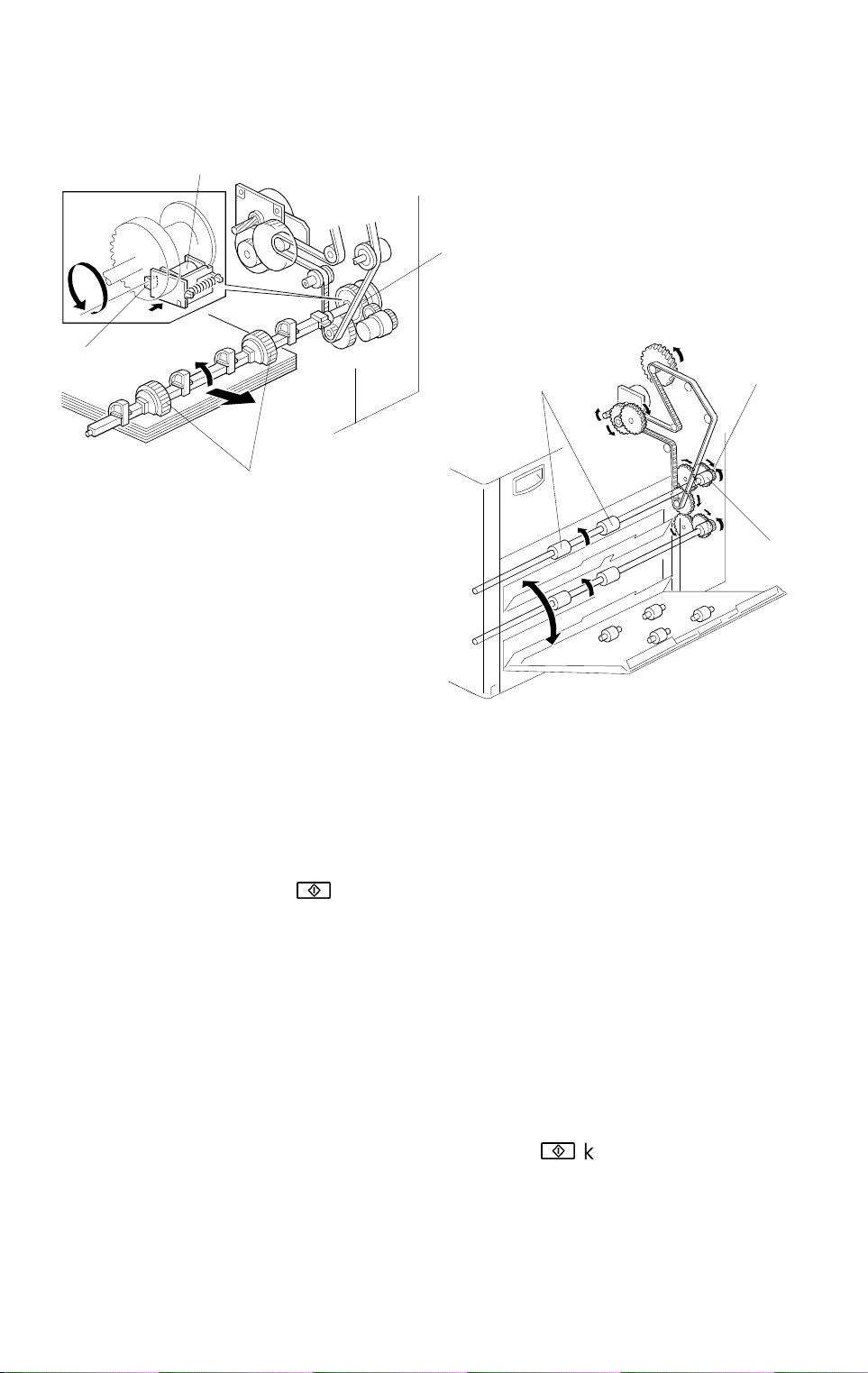
6.3 PAPER FEED AND DRIVE MECHANISM
[E]
[D]
[C]
A245D502.wmf
[A]
[F]
[B]
[G]
A245D503.wmf
Through several gears and a timing belt, main motor rotation is transmitted to
the tray paper feed clutch gear [A] and the relay roller clutch gear [B].
-Feed rollers-
The tray paper feed clutch gear is on the same shaft as the semicircular
feed rollers [C]. After the
!
key is pressed, the tray paper feed clutch [D] is
energized for 250 milliseconds to release the stopper [E]. Then main motor
drive is transmitted, and the feed rollers make one complete rotation to feed
the top sheet of paper, which is enough for the leading edge of the paper to
be caught by the relay rollers [F]. The feed rollers stop when the stopper
drops back into the notch at the end of one complete turn.
-Relay rollers-
The relay roller clutch gear is on the same shaft as the relay rollers. The
rotation timing of the relay rollers is controlled by the relay roller clutch [G].
The CPU energizes the relay roller clutch after the
!
key is pressed (at the
same time as the tray paper feed clutch). Paper is fed from the relay rollers to
the registration rollers.
12
Page 15
26 September 1997 PAPER FEED
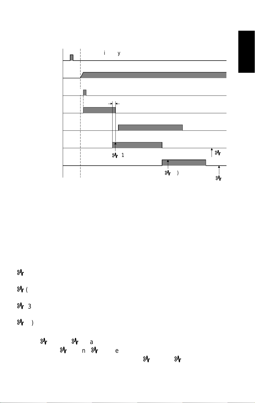
6.4 PAPER FEED AND MISFEED DETECTION TIMING
Start Key
Main Motor
Upper Tray
Paper Feed Clutch
Upper Relay Roller
Clutch
Registration Clutch
Registration Sensor
Exit Sensor
0
A4 sideways
0.30 0.55
0.30
A
0.10
2.13
2.05
(1)
4.48
A
(2)
(seconds)
6.50
(3)
A
6.78
(4)
A
A245D508.wmf
The registration sensor and the exit sensor are used for misfeed detection. If
the CPU detects a misfeed, the Check Paper Path and the Location
indicators turn on.
Copier
Just after the main switch is turned on, the CPU checks these sensors for
any jammed paper.
During the copy cycle, the CPU performs four kinds of misfeed detection. The
following explains jam detection timing for copying on A4 sideways paper
from the upper paper tray unit.
A
(1): Checks whether the registration sensor is actuated within 2.05
seconds after the main motor starts rotating.
A
(2): Checks whether the exit sensor is actuated within 4.48 seconds after
the main motor starts rotating.
A
(3): Checks whether the copy paper has passed through the registration
sensor 6.50 seconds after the main motor starts rotating.
A
(4): Checks whether the copy paper has passed through the exit sensor
6.78 seconds after the main motor starts rotating.
NOTE:
A
(1) and A (2) are detected from the leading edge of the copy
A
paper.
copy paper. The detection timing for
(3) and A (4) are detected from the trailing edge of the
A
(3) and A (4) will vary with
the copy paper size in use.
13
Page 16
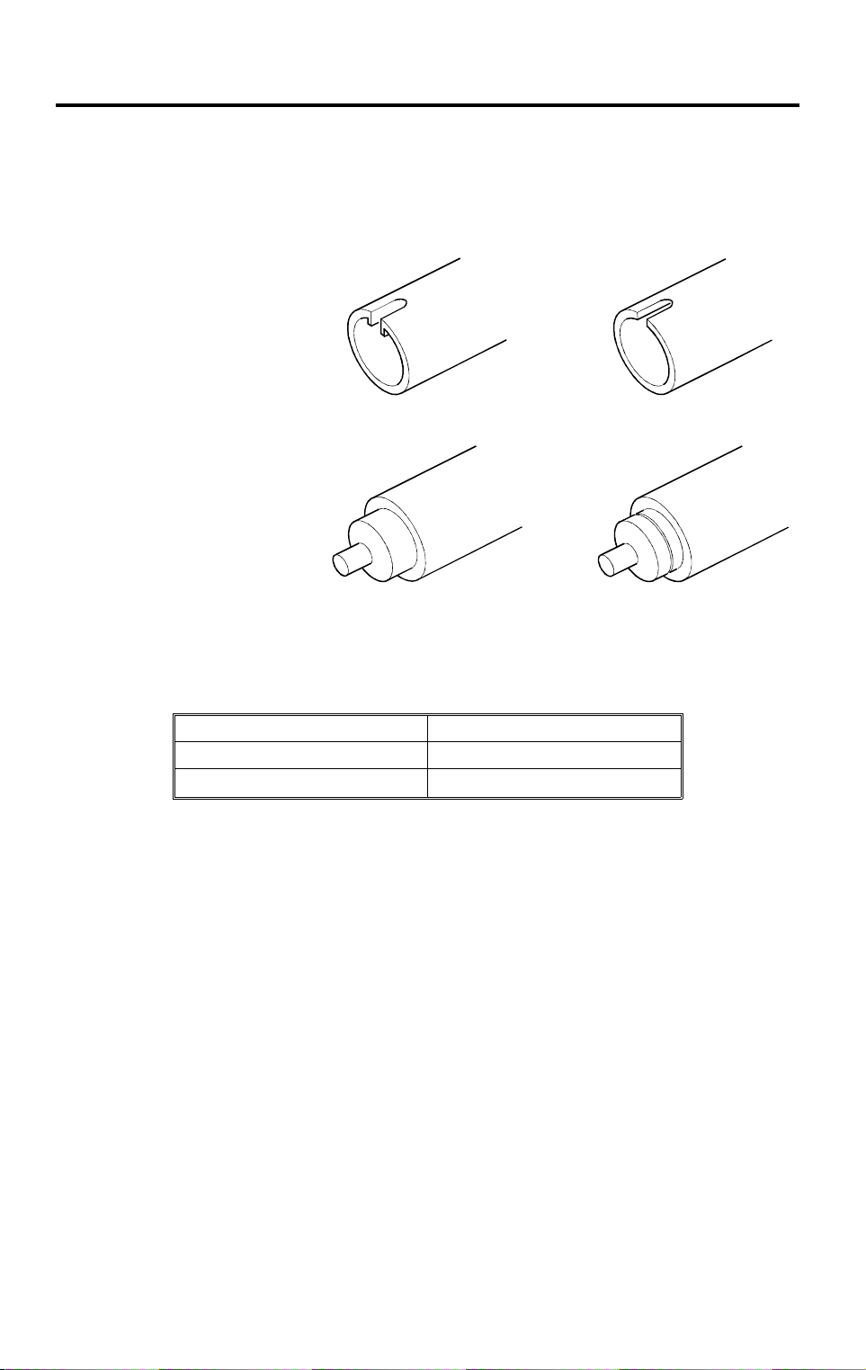
IMAGE FUSING 26 September 1997
7. IMAGE FUSING
1. Both the hot roller and pressure roller for the A245 are different from the
A219. To distinguish between the two types of roller, check the end of the
roller shaft as described below.
HOT ROLLER
- A219 -
- A245 -
A245D504.wmf
PRESSURE ROLLER
- A219 -
A245D505.wmf
- A245 -
A245D506.wmf
A245D507.wmf
2. Due to the increase in copier CPM, the thickness of the metal core of the
hot roller has been increased for the A245 copier. This causes the ready
temperature to be higher, and the temperatures are as follows:
A245 copier A219 copier
172°C: 120 V machines 165°C: 120 V machines
177°C: 230 V machines 172°C: 230 V machines
Also, to achieve the same warm-up time as for the A219 copier in the 230 V
machines, the fusing lamp wattage has been increased from 650 W to 760 W.
For the 120 V machine, the warm-up time specification is slightly longer than
for the A219, so the lamp is not changed.
3. FUSING IDLING (SP116)
Fusing idling can be selected with SP116. This mode should be used
when the copier has fusing problems with copies which are made soon
after warm up. This problem is most likely to occur in low temperature
locations where the wall outlet condition is also not stable. Please note
that when this mode is selected, copier warm-up will take a couple of
seconds extra, and the first copy time will not be within specification.
When the start key is pressed, fusing idling is performed for 2 seconds. If
the temperature of the fusing unit is below the operating temperature by
up to 10°C, copying starts. If the detected temperature is more than 10°C
lower than the operating temperature, fusing idling will continue until the
detected temperature reaches 180°C. This will take 6 ~ 7 seconds longer
to warm up than if fusing idling is not used.
14
Page 17

26 September 19 97 INSTALLATION
8. INSTALLATION
8.1 COPIER ACCESSORY CHECK
Check the quantity and condition of the accessories in the box against the
followings list :
1. Model Name Decal (-10, -22 machines)
2. Symbol Explanation Decal - Multi-language
3. Installation Procedure - Multi-language (-10, -15, -22, -26 machines)
4. Operation Instructions English (-10, -15, -17, -19, -22, -26, -29, -39
machines)
5. NECR - English (-17 machines)
6. NECR - Multi-language (-27, -29, -39 machines)
7. Copy Tray
Copier
8. User Survey Card (-17 machines)
9. Paper Set Direction Deal - Multi-language (-22, -26, -27 machines)
15
Page 18
INSTALLATION 26 September 1997
8.2 COPIER INSTALLATION PROCEDURE
[B]
[A]
A245I500.wmf
[D]
[C]
[F]
[H]
A245I501.wmf
CAUTION
[E]
A245I506.wmf
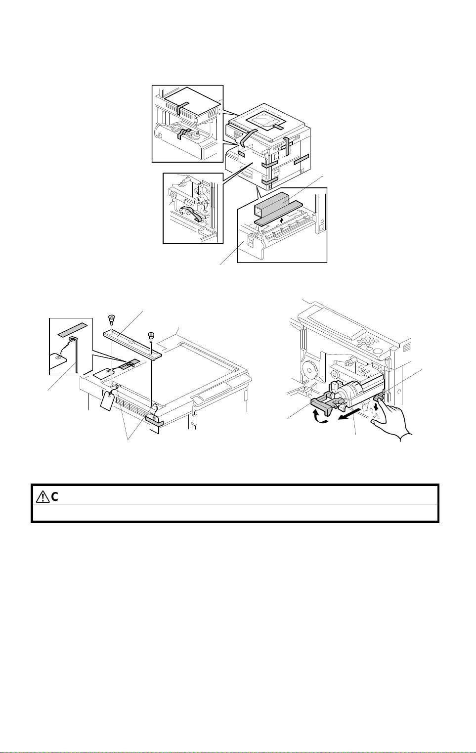
Do not plug in the power cord before starting the following procedure.
1. Remove all strips of tape shown above.
[G]
2. Pull out the paper trays [A], and remove the cardboards [B].
3. Open the platen cover and remove the lock pin [C].
NOTE:
Save the lock pin for future shipping.
4. Remove the left side scale [D] (2 screws) and remove the lock pins [E].
NOTE:
Save the lock pins for future shipping.
5. Open the front cover and raise the toner bottle holder lever [F].
Then pull down the securing lever [G], and remove the toner bottle holder
[H].
16
Page 19
26 September 19 97 INSTALLATION
[B]
Copier
[F]
[C]
[E]
[D]
[A]
A245I502.wmf
[G]
A245I503.wmf
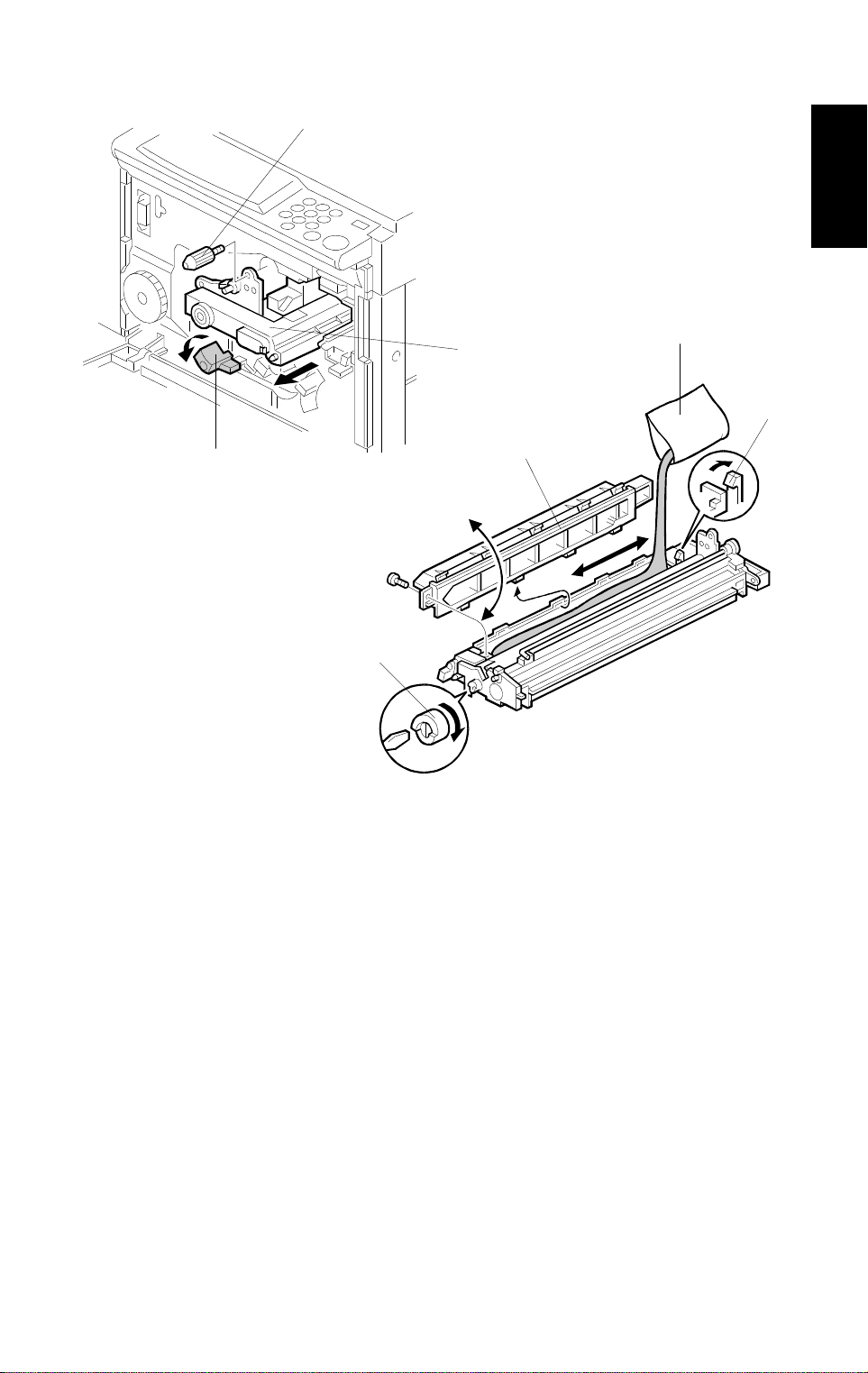
6. Turn the "B1" lever [A] counterclockwise to lower the transfer corona unit.
7. Remove the knob screw [B] and gently pull out the imaging unit [C].
Then place it on a clean sheet of paper.
8. Remove the cover [D] from the imaging unit (1 screw and 1 snap [E]).
9. Pour in the developer [F] evenly into the imaging unit. Then rotate the
outer gear [G] for one or two turns to distribute the developer as shown.
NOTE:
When installing new developer or manually rotating the
development roller, always make sure to turn the gear in the
direction shown above. Also do not rotate the gear more than 3
turns to prevent damage to the unit.
10. Remount the cover on the imaging unit, and install the unit in the copier
(1 knob screw).
17
Page 20

INSTALLATION 26 September 1997
[B]
[D]
[F]
[C]
[H]
[G]
[A]
[E]
A245I504.wmf
11. Install the toner bottle holder [A] in the copier as shown.
12. Shake the toner bottle [B] well.
NOTE:
Do not remove the bottle cap [C] of the toner bottle at this time.
13. Unscrew the bottle cap and insert the toner bottle into the holder, so that
the rib [D] rides the rail [E].
NOTE:
Do not open the inner bottle cap [F].
14. Reposition the holder by making sure that the securing lever [G] clicks.
Then press down the holder lever [H] to secure the bottle. Close the front
cover.
18
Page 21

26 September 19 97 INSTALLATION
[E]
[C]
[B]
[A]
[C]
[D]
A245I505.wmf
15. Pull the paper tray [A] out and turn the paper size dial [B] to select the
appropriate size. Adjust the side guides [C] and the end guide [D] to
match the paper size.
NOTE:
1) Make sure the stack of paper is aligned, and that there is no
space between the side guides and the paper stack.
Copier
2) Always push the paper tray in gently.
16. Plug in the copier and turn on the main switch. Wait until it warms up. (It
takes about 45 seconds.)
17. Enter the SP mode as follows:
1) Press the "Clear Modes" key.
2) Enter "107" using the numeric keys.
3) Hold down the "Clear/Stop" key for more than 3 seconds.
18. Perform the TD sensor initial setting as follows:
1) Enter "66" using the numeric keys.
2) Press the "Auto Image Density" key.
NOTE:
The machine will automatically stop when completed. (It takes
about 1 minute.)
19. Turn the main switch off and on to exit SP mode.
20. Check the copy quality and machine operation.
21. Inform the customer of the notes in step 13 concerning the paper tray.
Also find out if the customer changes paper sizes frequently. If not, inform
the customer that the side guides can be fixed with a screw [E] to achieve
better paper feed quality (use a tapping screw less than 8 mm long).
19
Page 22

INSTALLATION 26 September 1997
8.3 UPPER AND LOWER TRAY HEATER INSTALLATION
(OPTION)
[G]
[H]
[A]
[D]
[E]
[B]
[F]
A245I507.wmf
NOTE:
[C]
1) The optional tray heaters keep copy paper dry. In humid
environments, copy paper may crease as it comes out of the
fusing unit. The heaters are available as service part. (See the
parts catalog.)
2) Tell the customer that even when the copier main switch is turned
off, the copier power cord should be plugged in.
Otherwise, the tray heater will not function.
CAUTION
Unplug the copier power cord before star ting the follo wing procedure.
1. Remove the rear cover [A] (2 screws).
2. Remove the paper trays.
3. Connect the interface harness [B] to the tray heater [C]. Then mount the
heater on the heater bracket [D] as shown (1 screw).
- LOWER TRAY -
4. Mount the heater bracket on the bottom of the copier main frame, while
passing the connector [E] through the opening [F] in the copier main
frame as shown (1 screw).
5. Remove the transformer [G] (2 screws).
6. Locate the red two-pin connector [H] at the rear of the copier, and
connect it to the heater’s connector (red), as shown.
20
Page 23

26 September 19 97 INSTALLATION
[K]
[I]
[J]
A245I507-2.wmf
Copier
- UPPER TRAY -
4. Mount the heater bracket while passing the connector [I] through the
round opening [J] in the copier main frame as shown (1 screw).
5. Locate the red two-pin connector [K] at the rear of the copier, and
connect it to the heater’s connector (red), as shown.
21
Page 24

PROGRAM MODE 26 September 1997
9. PROGRAM MODE
9.1 SP MODE QUICK REFERENCE TABLE
NOTE:
1) Items written in
bold italic letters
are newly added service
programs.
2) Items written in
SP Mode
No.
4 Forced Start (Free Run) 36 TD Sensor Sensitivity Setting
5
6 Misfeed Detection Off
7
8 Input Check
9 Output Check
10
11 All Indicators On 45 Registration Buckle Adjustment
14
15
16 Count Up/Down Selection *48 Light Intensity Adjustment
17 Narrow Paper Select Mode 49 Fusing Temperature Adjustment
18
19 ADS Priority 51 Exposure Lamp Voltage Displ ay
22 SADF Shut Off Time 52 Fusing Temperature Disp l ay
24
27 A3/DLT Double Count
28 Auto Sort Select 55 TD Sensor Output Display Data
29
30 Toner Supply Mode Selection 57 ADS Output Voltage Display
31
32
33
34
35
Free Run with Exposure Lamp
Off
Free Run
Scanner Free Run
Auto Shut Off Time
(Energy Star)
Auto Reset Time Setting
(Energy Saver)
Auto Feed Station Shi ft
Horizontal Edge Margin Wid th
Adjustment
Fusing Temperature Control
Selection
Toner Supply Amount
(TD Sensor Mode)
Toner Supply Amount
(Fixed Supply M ode)
Image Bias Adjustment
(Manual ID Mode)
Image Density Adj ustment
(ADS Mode)
Total Toner Supply ON Time
During Tone r Near/End Conditi on
Function
are modified service programs.
bold
SP Mode
No.
38
39 VL2 Correction Interval
*41
*42 Registration Adjustment
*43 Vertical Magni fication Adjustment
*44
46
*47
50
53
54 TD Sensor Gain Adjustment
56
58
59
60
61
62
Toner Density Adjustment
Lead Edge Erase Margin
Adjustment
Horizontal Mag nification
Adjustment
Registration Buckl e Adjustment A5 Paper
Focus Adjustment
Fusing Ready Temperature
Adjustment
TD Sensor Target Cont r ol
Voltage Adjustment
ADS Reference Voltage
Adjustment
Image Adjustment at ID Level 1
Optics Temper at ur e D i splay
Drum Potential Measurement
(With Paper)
Drum Potential Measurement
(Without Paper)
Correction Interval
V
L
Function
* Items listed on the factory setting data sheet
22
Page 25

26 September 19 97 PROGRAM MODE
SP Mode
No.
63 Forced Toner Supply 90 Factory Data and Counter Clear
R
64 V
66 TD Sensor Initial Setting 93 VR Correction Reset
67 TD Sensor Initial Output Display 94 V
68 V
69 Imaging Unit Counter Displ ay 96 Toner End Force Cancel
Correction Value
L2
Correction Selection 95 VL Correction Reset
Function
70 User Code Mode
71 Sorter Operation 98 Total Counter Clear
73 User Code Counter Display
74
76
77
78 Auto Energy Saver Mode On/Off 106 DF Original Counter Display
81 Factory Initialization
82 Data Communication 130 Total Service Calls
83 Factory Potential Adjust ment 131 Total Misf eeds
88 Total Copy Counter Display
* Items listed on the factory setting data sheet
Special Paper Size Setting
Sorter Bin Capacity
Auto Shut Off (Energy Star)
On/Off
SP Mode
No.
Function
92 User Code Co unt er Clear
L2
Correction Reset
97 Servic e Call (E5) Reset
99 Clear All Memory
100
101
102
By-pass Feed Copy Co unter
Display
Upper Paper Feed Tray Copy
Counter Display
Lower Paper Feed Tray Copy
Counter Display
116 Fusing Id ling
Copier
9.2 UP MODE AND SP MODE CROSS REFERENCE TABLE
NOTE:
UP Mode No. SP Mode No. Function
Items written in
1 34 Image Density Adjustment (ADS Mode)
2 17 Narrow Paper Select Mode
3 15 Auto Res et Ti m e Set ting (Energy Saver)
4 78 Auto Energy Saver Mode On/Off
5 14 Auto Shut Of f Tim e Setting (Energy Sta r)
6 38 Toner D ensity Adjustment
7 16 Count Up/Down Selection
bold italic letters
8 73 User Code Counter Display
9 92 User Code Counter Clear
10 77 Auto Shut Off (Energy Star) On/Off
11 58 Image Adjustment at ID Level 1
are newly added programs.
23
Page 26

PROGRAM MODE 26 September 1997
9.3 SERVICE PROGRAM MODE TABLE
1. In the
2. In the
Function
Settings
column, comments (extra information) are in italics.
column, the default value is printed in bold letters.
3. If there is a ✝ mark in the Mode No. column, copies can be made within
this SP Mode.
Mode No. Function Settings
Forced Start
(Free Run)
4
Free Run with
Exposure
Lamp Off
5
Misfeed
Detection Off †
6
Free Run Performs a free run with the exposure lamp on.
7
Performs a free run with a forced start.
Press the ! key to start the free tun.
Press the $ key to stop the free run.
If this mode is swi t ched on, the copier st ar ts the free
run even if the fusing temperature has not reached
the required value yet.
This mode i s per f o r m ed w i t h the selected paper size
and magnif i cat i on ratio without the paper feed clutch
or total counter increment.
Normally, use SP7 to prevent fusing-related
service call conditions from occurring.
A free run is performed without exposure.
Press the ! key to start the free run.
Press the $ key to stop the free run.
This mode i s per f o r m ed w i t h the selected paper size
and magnif i cat i on ratio without the paper feed clutch
or total counter increment.
Normally, u se SP7 t o reduce the cleaning blade
load.
Copies are made without misf eed detection by the
registration, exit sensors, and sorter paper sensor.
Press the ! key to make a copy. It stops when
reaching th e set count, or when the $ key is
pressed.
Use this mode to check whether a pap er misfeed
was caused b y a sensor malfunction.
The total counter increments when copi es ar e
made in this mode.
Press the ! key to start the free run.
Press the $ key to stop the free run.
This mode i s per f o r m ed w i t h the selected paper size
and magnif i cat i on ratio without the paper feed clutch
or total counter increment.
Before starting, close the platen cover to reduce
the clea n ing blade lo ad.
24
Page 27

26 September 19 97 PROGRAM MODE
Mode No. Function Settings
Input Check †
Enter the desir ed number given in th e following
table. The magnification in di cator is used to disp l ay
the input data from the sensors whi l e making a
normal copy.
Press the ! key to perform this mode.
Copier
Component
No.
1
2
3
*4
*5
8
9
10
8
12
13
14
16
17
18
19
20
21 ADF Lift Switch ADF Closed ADF Opened
22
Sensor/
Switch/Signal
Registrat ion Sensor Paper Not
Exit Sensor Paper Not
By-pass Feed
Paper End Se nsor
Upper Tray Paper
End Sensor
Lower Tray Pa per
End Sensor
High Voltage Leak
Signal
Power Suppl y
Board Signal
Right Vertical
Guide Switch
Scanner HP Sensor
4th/5th Mirror HP
Sensor
Lens HP Sensor
Sorter Paper Sensor Paper Not
Sorter Wheel Switch Switch
Sorter Bin HP
Switch
Sorter Switch Sorter
ADF Installation ADF Not
Key Counter Set
Signal (Not Used)
Sensor Not
Sensor Not
Sensor Not
Key Counter
Reading
01
Present
Present
Paper Not
Present
Paper
Present
Paper
Present
No Leak
Signal
120 V 230 V
Cover
Closed
Actuated
Actuated
Actuated
Detected
Actuated
(Switch
Pushed in:
Wheel
Moving)
Switch Not
Actuated
Closed
Installed
Not Set
Paper
Present
Paper
Present
Paper
Present
Paper Not
Present
Paper Not
Present
Leak Signal
Detected
Cover Open
Sensor
Actuated
(HP)
Sensor
Actuated
(HP)
Sensor
Actuated
(HP)
Paper
Detected
Switch Not
Actuated
Switch
Actuated
(HP)
Sorter
Opened
ADF
Installed
Key Counter
Set
* Newly added or modified items from the A219 copier.
25
Page 28

PROGRAM MODE 26 September 1997
Mode No. Function Settings
Output Check
Use to turn on in di vi dual electrical components.
Enter the desir ed number given in th e following
table.
Press the ! key to turn on the electrical
component.
Press the $ key to turn off the electrical
component.
Component
No.
1
2 Charge Corona
3 Transfer Corona
4 Discharg e Plate
5
6 Erase Lamp All LEDs On
7
8
9
9 Optics Cooling Fan
10
11 Toner Supply Motor
12
14 Sorter Roller Drive Motor
15
16
17 Registration Clutch
18 By-pass Paper Feed Clutch
*19
*20
*21 Upper Relay Roller Clutch
*22 Lower Relay Roller Clutch
23 Total Counter
24 Key Counter Not Used
Electrical Component Note
Main Motor + Quenching
Lamp + Exhaust F an
Motor (H i g h Speed)
Development Bias Voltage Standard Voltage
Machine Shut Off Main Switch Relay
Exhaust Fan Motor
(High Speed)
Exposure Lamp + Optics
Cooling Fan
Toner Supply Motor
(Reverse)
Sorter Bin Drive Mo to r
(Bin Up)
Sorter Bin Drive Mo to r
(Bin Down)
Upper Tray Paper Feed
Clutch
Lower Tray Pa per Feed
Clutch
for Manual ID Level
4.
Off.
Moves One Bin Up.
Moves One Bin
Down.
* Newly added or modified items from the A219 copier.
26
Page 29

26 September 19 97 PROGRAM MODE
Mode No. Function Settings
Scanner Free
Run
10
Start a scanner free run.
Press the ! key to start the free run.
Press the
key to stop the free ru n.
$
This mode i s per f o r m ed i n accordance wit h t he
selected paper size and magn i fication ratio.
All IndicatorsOnTurns on all the indicators on the operation panel for
11
30 seconds. They will turn off automatically after 30
seconds.
To turn off the indicators, press the key.
Auto Shut Off
Time Setting
(Energy Star)
14
Selects the auto shut off time.
The copier m ai n sw i t ch is shut off autom at i cal l y after
the selecte d aut o shut off time, if SP77 i s at "0".
0: 30 min .
1: 15 min.
2: 60 min.
3: 90 min.
4: 120 min.
5: 240 min.
Copier
Auto Reset
Time Setting
15
(Energy Saver)
Selects an aut o re set time of 1 or 3 minutes, or
cancels this m ode.
The copier goes to energy saver mode
automatically after the selected auto reset time, if
SP78 is at "1".
Count
16
Up/Down
Selection
Narrow Paper
Select Mode
17
Selects count up or count down.
Selects narrow paper feed mode fo r the by-pass
feed table.
Use this mode to f eed non-standard paper sizes
that are too narr ow to be detected by the b y- pass
feed paper end sensor. In this case, the copier will
operate even if the Add Paper indicator is on.
Auto Feed
Station Shift
18
Selects auto feed station shift m ode.
The copier aut om atically shift s t o th e ot her paper
feed station when paper runs out, if it holds the
same size of p aper.
ADS Priority Specifies whether th e copier defaults to ADS or
19
SADF Shut Off
22
Time
Horizontal
Edge Margin
24
Width
Adjustment
Manual mode when the main switch is turned on.
Selects the shut o ff time for SADF mode.
The DF must be installed on the m achine.
Selects wheth e r the side erase mech ani sm changes
when the optio nal document feeder i s i nst al l ed.
See "Detaile d D escriptions - Eras e" f or more details.
0: 1 min.
1: 3 min.
2: None
0: Up
1: Down
0: No
1: Yes
0: Auto Shift
1: Manual
0: ADS
1: Manual
0: 5 s.
1: 60 s.
0: DF Mode
1: Always stays
in Platen Mode
27
Page 30

PROGRAM MODE 26 September 1997
Mode No. Function Settings
A3/DLT
Double Count
Specifies whether the counter is doubled for A3/DLT
paper.
0: OFF
1: ON
If "ON" is selected, the total coun te r, el ectrical total
27
counter (SP88), and the current user code counter
count up twice when A3/DLT copy paper is used.
This function is not applicab l e w hen using the
by-pass feed t abl e, since the by-pass feed table can
not detect cop y paper size.
Auto Sort
Select
In Auto Sort Mode, the sorter is automatically
selected when more than 1 original is set on the DF
0: Manual
1: Auto Sort
table and the ent ered copy quantity i s greater than 1
28
and less than 11 .
In Manual mode, sort mode has to be selected at
the operation panel.
The sorter and DF must be install ed on the machine.
Fusing
Temperature
29
Control
Selection
Toner Supply
Mode Selection
Selects the fusing temperature control mode.
After selecting the control mode and turning th e
main switch off/on, the fusing temperature control
mode is changed.
Selects the tone r supply system.
Normally, this value should not be changed.
0: ON/OFF
control
1: Phase
control
Default = 0
30
Toner Supply
Amount
(TD Sensor
31
Mode)
SP
Setting
Toner Supply System Note
Detect supp ly mode using
0
the initial TD sensor
setting.
Detect supp ly mode using
1
the target TD sensor
voltage set with SP53.
Detect supp ly mode (fixed
2
amount) using the initial
TD sensor setting.
Detect supp ly mode (fixed
amount) using the target
3
TD sensor vol tage set
with SP53.
Fixed supply mode. Use only in abnormal TD
4
Default
sensor conditions.
See SP31/SP32 for the toner supply amount.
Determin es how much toner is su ppl i ed in detect
supply mode .
Select the toner supply time from 0. 0 s t o 5. 0 s i n
0.1 s step s.
See "Detaile d D escriptions-Toner Supply Contr ol "
for more details.
0 ~ 50
Default = 4
(0.4 s)
28
Page 31

26 September 19 97 PROGRAM MODE
Mode No. Function Settings
Toner Supply
Amount
(Fixed Supply
Mode)
Determines how much toner is supplied in fixed
supply mode a nd i n detect supply (fixed amount)
mode.
For exampl e, if the user normall y makes copies of
0 ~ 7
Default = 0
A4 originals that are about 7% black, select the 7%
setting for be st results.
Copier
32
Image Bias
Adjustment
(Manual ID
Mode)
33
SP
Setting
0 3.5% 0.3 s Default
1 7.0% 0.6 s
2 15% 1.2 s
3 30% 2.4 s
4 45% 3.6 s
5 60% 4.8 s
6—
7 0% 0 No toner supply
Ratio
Supply
Time
∞
Continuous supply
Note
See "Detailed Descriptions - Toner Supply Control"
for more details.
Adjusts the devel opment bias volt age used in
manual ID m ode. This adjustm ent af fe ct s al l manual
ID settings. Use this SP mode to adjust the density
of pale gray areas.
SP Setting Setting Dev. Bias Note
0 Normal 0 Default
1 Darkest +40 V
2 Darker +20 V
3 Lighter –20 V
4 Lightest –40 V
0: Nor mal
1: Darker
2: Darkest
3: Lighter
4: Lightest
See "Detaile d D escriptions - Devel opment" for more
details.
29
Page 32

PROGRAM MODE 26 September 1997
Mode No. Function Settings
Image Densi ty
Adjustment
(ADS Mode) †
Selects the imag e density level in ADS mode.
The development bias and the e xposure lamp
voltages are i ncreased or decreased.
This adjustment affects copi es made in ADS mode.
0: Nor mal
1: Light
2: Dark
3: Lighter
4: Darker
SP Setting Setting Dev. Bias Exposure Lamp
0 Normal 0 0
1 Lighter –40 V 0
34
2 Darker +40 V 0
3 Lightest –40 V +4 steps
4 Darkest + 40 V –4 steps
The exposure l amp setting spec i fies the change
relative to the base exposure lamp voltage (Vo) in
SP48, 1 step of the lam p vol t age equals 0.5 V for
120 V (NA), and 1.0 V for 230 V (EU ) machines.
See "Detaile d D escriptions - Devel opment" for more
details.
Total Toner
Supply ON
Time During
35
Toner
Near/End
Condition
Selects the tone r supply motor on time after every
copy job during a toner near/end condition.
See "Detaile d D escriptions - Toner Supply" for mor e
details.
This SP mode is intended for designer use only.
1: 10 s
2: 20 s
3: 30 s
4: 40 s
5: 50 s
6: 60 s
TD Sensor
Sensitivity
Setting
36
Adjust the sensitivity of the TD sensor.
Normally, this value should not be changed.
SP Setting Sensitivity (V/wt%) Note
00
10.05
20.10
Å
12 0.60
13 0.65
14 0.70
15 0.75 Default
16 0.80
Å
19 0.95
20 1.00
↓
↓
0.05 per step
0.05 per step
The toner supply motor on time and/or the toner
density are ch anged by this setting. See
"Detailed Descriptions - Toner Supply Control"
for mo re details.
0 ~ 20
Default = 15
30
Page 33

26 September 19 97 PROGRAM MODE
Mode No. Function Settings
Toner Density
Adjustment
38
V
L2
Correction
39
Interval
Adjusts copy qu al i t y by changing the tone r
concentrati on i nside the develo pm ent unit.
This can be ad j ust ed using a UP mod e.
See "Detailed Descriptions - Toner Supply Control"
for more details.
Selects the inter val for detectin g th e st andard light
L2
intensity of th e w hi t e pl at e f o r the V
correction.
For Small CV users in a dusty envir onment, 200
0: Nor mal
1: Darker
2: Lighter
3: Darkest
4: Lightest
0: 500 copies
1: 200 copies
copies may be a better setting.
Lead Edge
Erase Margin
41
Adjustment †
Registration
Adjustment †
42
Adjusts the lea d edge erase marg in . 0 ~ 15
0.5 mm per step (–4.0 mm to +3.5 mm).
See "Replace ment and Adjustment - Copy Quali ty
Adjustment" for details.
Adjusts the registration. 0 ~ 15
0.5 mm per step (–4.0 mm to +3.5 mm). See
Default = 8
(2.5 mm from
leading edge)
Default = 8
"Replacement and Adjustment - Copy Quality
Adjustment" for details.
Vertical
Magnification
Adjustment †
43
Adjusts mag ni f i cat i on in the paper travel di rection by
changing the scanner speed.
0.2% per step (–3.2% to +3.0%).
Check the foc usi ng after doing this SP mode, and
0 ~ 31
Default = 16
adjust with SP47 if necessary.
See "Replace ment and Adjustment - Copy Quali ty
Adjustment" for details.
Horizontal
Magnification
Adjustment
44
Adjusts mag ni f i cat i on perpendicul ar to the direction
of paper travel , by changing the home position of
the lens and m i rrors.
✝
0.2% per step (–4.0% to +6.0%).
0 ~ 50
Default = 20
Check the foc usi ng after doing this SP mode, and
adjust with SP47 if necessary.
See "Replace ment and Adjustment - Copy Quali ty
Adjustment" for details.
Registration
45
Buckle
Adjustment †
Registration
Buckle
46
Adjustment A5 Paper †
Focus
Adjustment †
47
Adjusts the amount of paper buckle in the
registration area.
0.5 mm per step (–4.0 mm to +3.5 mm).
When feedin g A5 si deways paper, th e registration
buckle can b e adj usted separately from the SP45
setting to reduc e t he buckle .
0.5 mm per step (0 mm to –5.0 mm).
Adjusts the 4th/5t h mirror positi on t o cor rect the
focus.
This mode m u st be done after vertical and
horizonta l magnification adj ustments (SP43 an d
0 ~ 15
Default = 8
Default = 0
0 ~ 100
Default = 40
(0.1 mm per
step)
SP44).
See "Replace ment and Adjustment - Copy Quali ty "
for details on how to do this adjustm ent.
Copier
31
Page 34

PROGRAM MODE 26 September 1997
Mode No. Function Settings
Light Intensit y
Adjustment †
Clean the optics, then adjust the e xposure lamp
voltage. The V
L
and VL2 corrections ar e reset
automatically when entering this mode.
120 V Machines
100 ~ 194
Default = 140
48
Fusing
Temperature
Adjustment
49
Fusing Ready
Temperature
Adjustment
50
Exposure
Lamp Voltage
Display
51
SP Setting
100 50.0 100
101 50.5 101
102 51.0 102
Å
150 75.0 150
Å
180 90.0 180 Max
Å
193 96.5 —
194 97.0 Max —
120 V (NA) Version 230 V (EU) Version
Lamp Voltage (V)
↓↓
↓↓
↓
—
Before performing this mode, clean the optics.
Then open SP33 and return the setting to the
normal value if it has been changed. Then adjust
the light intensity using an OS-A3 Test Chart with
the platen co ver pl aced over it. After adj usting the
light intensity, adjust the ADS Reference Voltage
Adjustment (SP56).
See "Replace ment and Adjustment - Copy Quali ty "
for details on how to do this adjustm ent.
Adjusts the cont rol temperature of the hot roller
during copying in 1°C steps.
Adjusts the ready temperature of th e hot roller
during the warm-up period in 1°C steps.
Normally, this value should not be changed.
Displays the current exposure lamp voltage.
For 120 V mach ines, the actual appl i ed
voltage = displayed value/2
The exposur e l am p t urns on for 10 secon ds w hen
this mode is selected. Do not repeat more than 5
times, to avoid overheating the optics cavity.
230 V Machines
100 ~ 180
Default = 140
120 V Machines
180°C ~ 195°C
Default = 190°C
230 V Machines
180°C ~ 200°C
Default = 190°C
120 V Machines
160°C ~ 175°C
Default = 172°C
230 V Machines
165°C ~ 180°C
Default = 177°C
0 ~ 247
32
Page 35

26 September 19 97 PROGRAM MODE
Mode No. Function Settings
Fusing
Temperature
52
Display †
Displays the fusing temperat ure detected by the
fusing thermi st or.
Press the ! key to monitor the te mperature
during the normal copy cycle.
TD Sensor
Target Contr ol
53
Voltage
Adjustment
TD Sensor
54
Gain
Adjustment
TD Sensor
Output Display
Data †
55
If the setting of SP30 (T oner Supply Mode
Selection) is 1 or 3, this value is used for the TD
sensor targe t vo l tage.
Normally, this value should not be changed.
When the TD Sens or initial setting i s per f ormed, this
mode is adjust ed automatica l l y.
Normally, this value should not be changed.
Displays the TD sensor output vol ta ge.
Press the ! key to monitor the out put voltage
during the normal copy cycle.
The output voltage will display "0" when this mode is
1 ~ 200
Default = 97
(0.02 V per step)
0 ~ 255
Default = 102
(0.04 V per step)
(0.02 V per
step) x Data
accessed after turning on the main switch without
making any copies.
ADS
Reference
Voltage
56
Adjustment
ADS Output
Voltage
Display †
57
Adjusts the ADS reference voltage.
After adjustin g th e li ght i nt ensity (SP48), place 5
sheets of A4(LT) white paper on the exposure glass
and select th i s m ode. Adjust the ADS voltage to 2.5
0.1 V using VR101 on the mai n control board.
V
±
Displays the ADS o ut put volt age.
Press the ! key to monitor the out put voltage
during the normal copy cycle.
For only this SP mode, the copies are ma de w i t h th e
ADS mode (other SP modes use manual ID lev el 4) .
Image
Adjustment at
Adjusts the image density at ID level 1 by changing
the development bias voltage.
0: Normal
1: Darker
ID Level 1
58
SP Setting Setting Dev. Bias Note
0 Normal –200 Default
1 Darker –140
Copier
Optics
Temperature
59
Display †
Drum Potential
60
Measurement
(With Paper)
Drum Potential
61
Measurement
(Without Paper)
Displays the optics temperat ur e det ected by the
optics therm istor.
Press the ! key to monitor the temperature
during the normal copy cycle.
Factory use only.
Factory use only.
33
Page 36

PROGRAM MODE 26 September 1997
Mode No. Function Settings
Correction
V
L
Interval
Sets the interval for V
lamp voltage (SP48) is increased by 1 step at the
L
correction. The exposure
0 ~ 8
Default = 2
set copy count interval.
SP Setting Exposure Lamp Note
0 + 2 steps/8,00 0 co pies
1 + 2 steps/6,00 0 co pies
2 +2 steps/4,000 copies Default
62
3 + 2 steps/2,00 0 co pies
4 + 2 steps/1,00 0 co pies
5 No Correction
6 +2 steps/500 copies
7 +2 steps/200 copies
1 step of the lamp voltage equals 0. 5 V for
N-American, and 1. 0 V fo r European machines.
See "Detailed Section Descriptions - Exposure
Lamp Voltage Control" for details.
Forced Toner
Supply
Forces the toner bottle to supply toner to the
development uni t .
0: 6 seconds
1: 3 seconds
This mode starts when the ! key is pressed,
63
and stops auto m atically after th e selected time.
Use this mode to achieve standard image
density whe n copy quality problem s i ndi cate
low toner.
R
Correction
V
64
Value
TD Sensor
Initial Setting
Sets the VR correction val ue.
Keep this at the default setting.
Performs the TD sensor initial setting.
This SP mode contr ol s t he voltage applied to the TD
Default = 0
sensor to mak e th e TD sensor output 1.9 ± 0.1 V.
After using SP66, check SP67 to see if the sensor i s
66
working corr ectly.
This mode is started by pressing the key
and stops auto m atically after about 1 minute.
Use this mode only af t er ins ta lli ng new
developer .
TD Sensor
67
Initial Output
Display
L2
V
Selection
68
Correction
Display the TD sensor initial setting output.
Selects or deselects VL2 correction.
Keep this setting a t 0.
(0.02 V x
displayed
value)
0: V
L2
Correction
1: No V
L2
Correction
34
Page 37

26 September 19 97 PROGRAM MODE
Mode No. Function Settings
Imaging Unit
Counter
Display
69
User Code
Mode
70
Sorter
71
Operation
User Code
Counter
Display
73
Special Paper
Size Setting
74
Shows the total num ber of copies ma de so far by
the imaging unit installed in the machine. This
counter is reset by SP93.
The first three di gi ts are dis played in t he
magnifica tion indicator.
Press the
Enables user code mode.
JP101 on th e main board must be cut.
It this mode is set, operators must enter a code to
make copies. The user codes are the following 5
numbers:
1101, 2202, 3303, 4404, 5505
Enables sorter oper at i on.
Displays the contents of each user code counter.
Use the 9 or : key to select a use r co de. The last
digit of the user code is displayed in the copy
counter. User counters count from 0 to 999999.
The first three di gi ts are dis played in t he
magnifica tion indicator.
Press the
Sets the appropriate paper size for special paper
loaded in the paper feed tray.
The "" mark on the paper si ze dial must be
selected to use this special feature.
When the pap er feed tray is selecte d, the
appropria te p aper size or the "
displayed and the copier will operate in accordance
with the set paper size.
key to view the last three digits.
*
key to display the last three digits.
*
" mark will be
0: No
1: Yes
0: No Sorte r
1: Sorter Installed
0:
(Universal)
1: A3
2:
(Universal)
3: B4
4: A4
5: A4R
6: B5
7: B5R
8: A5
9: B6
13: DLT
14: LG
15: LT
16: LTR
17: HLT
19: F
27: 8 k
28: 16 k
(Sideways)
29: 16 k
(Lengthwise)
Copier
Sorter Bin
76
Capacity
Sets the stock quantity limits. If set to 1, the
maximum am ount of copies dep ends on the paper
size (see the specifications for the sorter).
35
0: No limit
1: Limit
Page 38

PROGRAM MODE 26 September 1997
Mode No. Function Settings
Auto Shut Off
(Energy Star)
77
On/Off
Selects the "Auto m at i c Shut of f" mode. 0: Yes
The copier aut om atically shut s i ts el f off at the auto
shut off time selected (SP14).
1: No
Default = 0 (NA)
Default = 1
(Others)
Auto Energy
78
Saver Mode
On/Off
Factory
81
Initialization
Data
82
Communic at i on
Factory
83
Potential
Selects the "Auto m at i c Ener gy Saver" mode. 0: No
The copier aut om atically goes t o Ener gy Saver
1: Yes
mode at the auto r eset time selected (SP15).
Factory use only.
Factory use only.
Factory use only.
Adjustment
Total Copy
Counter
Display
88
Displays the total (electrical) copy counter.
The first three di gi ts are dis played in t he
magnifica tion indicator.
Press the
key to view the last three digits.
*
The mechani cal total counte r and the electric al
total count er may not always di splay the same
value, becaus e of initial differences in the
counter va lues.
Factory Data
90
and Counter
Factory use only.
Clear
User Code
Counter Clear
92
R
V
Correction
Reset
93
Resets all the user code counters (SP73).
To clear, enter "1" then press the key and the
key at the same time.
*
Resets the drum residual volta ge correction cou nt er
for the VR correcti on.
To clear, enter "1" then press the key and the
key at the same time.
*
0: No
1: Yes
0: No
1: Yes
Use this mode only af t er ins ta lli ng a new drum.
L2
Correction
V
Reset
Resets the exposure lamp data a nd counter for the
L2
correction. Always perform this mode with SP95
V
0: No
1: Yes
as a set.
94
To Clear, ent er "1" t hen press the key and the
key at the same time.
*
Normally not needed in the fiel d, as this is handl ed
by SP48.
L
Correction
V
Reset
Resets the exposure lamp data a nd counter for the
L
V
correction. Always perform this mode with SP94
0: No
1: Yes
as a set.
95
To clear, enter "1" then press the key and the
key at the same time.
*
Normally not needed in the fiel d, as this is handl ed
by SP48.
36
Page 39

26 September 19 97 PROGRAM MODE
Mode No. Function Settings
Toner End
96
Force Cancel
The Toner End co ndi t i on is canceled forci bly.
By pressing the key to enter this SP mode, th e
toner end condi t i on is canceled.
Service Call
97
(E5) Reset
Resets a service call (E5) condition.
Turn the main swi t ch off and on to chec k i f the
service call condition is reset.
Total Counter
Clear
98
Clears the total (electrical) counter.
Normally, this SP mode should not be
performed.
To clear, enter "1" then press the key and the
key at the same time.
*
0: No
1: Yes
To avoid reset t i ng t he counter by mistake, the
counter is reset only when the
key and the
*
key are pressed at the same time .
Clear All
Memory
99
Clears all counters and returns all modes to the
default settings. See the Clear All Memory
Procedure in this section for more details.
Normally, this SP mode should not be
performed.
This SP mode is required only when replacing the
EEPROM, or when the copier malfunctio ns due to a
damaged EEPROM.
0: No
1: Yes
To clear, enter "1" then press the key and the
key at the same time.
*
To avoid reset t i ng t he counter by mistake, the
counter is reset only when the
key and the
*
key are pressed at the same time .
By-pass Feed
Copy Counter
Display
100
Displays the total (electrical) copy counter for the
by-pass feed t able.
Since the copy co unt er for displaying t he current SP
mode number has only 2 digits, the m anual image
density indi cator is used to disp l ay t he f i rst digit.
The first three di gi ts are dis played in t he
magnifica tion indicator.
Upper Paper
Feed Tray
Copy Counter
Display
101
Press the
Displays the total (electrical) copy counter for the
upper paper fe ed t ray.
Since the copy co unt er for displaying t he current SP
mode number has only 2 digits, the m anual image
density indi cator is used to disp l ay t he f i rst digit.
key to view the last three digits.
*
The first three di gi ts are dis played in t he
magnifica tion indicator.
Press the
key to view the last three digits.
*
Copier
37
Page 40

PROGRAM MODE 26 September 1997
Mode No. Function Settings
Lower Paper
Feed Tray
Copy Counter
Display
102
DF Original
Counter
Display
106
Displays the total (electrical) copy counter for the
lower pape r feed tray.
Since the copy co unt er for displaying t he current SP
mode number has only 2 digits, the m anual image
density indi cator is used to disp l ay t he f i rst digit.
The first three digits are displayed in the
magnifica tion indicator.
Press the * key to view the last thr ee di gits.
Displays the total (electrical) number of originals fed
from the DF.
Since the copy co unt er for displaying t he current SP
mode number has only 2 digits, the m anual image
density indi cator is used to disp l ay t he f i rst digit.
The first three di gi ts are dis played in t he
magnifica tion indicator.
Fusing Idling
116
Press the
Selects fusing idling during warm-up. This mode
should be used f or tr oubleshooting purposes only.
See "Detaile d D escriptions" for m ore details.
If this mode is selected, inform the customer
key to view the last three digits.
*
0: No
1: Yes
that the first copy time will not be within
specification.
This mode i s enabled after turn i ng t he main switch
off/on.
Total Service
Calls
130
Displays the total number of ser vi ce call conditions.
Since the copy co unt er for displaying t he current SP
mode number has only 2 digits, the m anual image
density indi cator is used to disp l ay t he f i rst digit.
The first three di gi ts are dis played in t he
magnifica tion indicator.
Press the
Total Misfeeds Displays th e to ta l n um ber of misfeeds excluding
original mi sf eeds in the DF.
Since the copy co unt er for displaying t he current SP
131
mode number has only 2 digits, the m anual image
density indi cator is used to disp l ay t he f i rst digit.
key to view the last three digits.
*
The first three di gi ts are dis played in t he
magnifica tion indicator.
Press the
key to view the last three digits.
*
38
Page 41

26 September 1997 PREVENTIVE MAINTENANCE SCHEDULE
10. PREVENTIVE MAINTENANCE SCHEDULE
10.1 MODIFIED PM TABLE
Below lists the modified PM table for the A219 and A245 copiers.
This information is also released in A219 RTB no. 1.
Copier
NOTE:
1) The amounts mentioned as the PM interval indicate the number of
copies.
2) Refer to "REGULAR PM PROCEDURE" in this section.
Symbol key: L: Lubricate R: Replace C: Clean I: Inspect A: Adjust
EM 45 k 90 k 135 k 180 k Notes
Optics
Reflector C C C C Silicone cloth
1st to 5th Mirrors C C C C Silicone cloth
6th Mirror C C C C Blower brush
Lens C C C C Blower brush
Exposure Glass
Platen Cover Sheet
Scanner Guide R od C , L C, L C, L C, L Dry cloth, Grease - CPL501
Scanner Guide Rai l
4th/5th Mirror Guide Rod
4th/5th Mirror Guide Rail
Blue Filter CCCCSoft cloth
Exposure Lamp /1 st
Scanner Ass’y
CCCCC
CCRCR
C, L C, L C, L C, L
C, L C, L C, L C, L
C, L C, L C, L C, L
Soft cloth dampened with
alcohol or water
Soft cloth dampened with
water
Dry cloth, Silicone Grease G501
Dry cloth, Silicone Grease G501
Dry cloth, Silicone Grease G501
Replace at 200 k copi es
Around the Drum
Charge Corona Wire C R R R R Blower brush
Transfer Cor ona Wire C C R C R Blower brush
Charge Corona Grid R R
Transfer Guide Plate C C C C C Soft cloth
End Blocks and Ca si ngs C C C C Blower br ush or dry cloth
Charge Corona Cleaning
Pad
Erase Lamp C C C C C Blower brush or dry cloth
QL C C C C C Blower brush or dry cloth
Discharge Plat e I C C C C Blower brush
IRRRR
39
Page 42

PREVENTIVE MAINTENANCE SCHEDULE 26 September 1997
EM 45 k 90 k 135 k 180 k Notes
Cleaning
Cleaning Blade I R I R Apply setting powder
Inside the Cleaning Unit
Cleaning Entra nce Seal
Development Unit
Developer R R R R
Development Unit
Entrance Seal
Toner Supply Unit I I I I
Development Drive Gear LLLLGrease - CPL501
Imaging Unit Low er Cover C C C C Dry cloth
Paper Feed (for each paper feed station)
Feed Roller
By-pass Feed Roller
Friction Pad
Tray Bottom Plate Pad
By-pass Bottom Plate Pad
Registration Roller
Paper Feed Guide
Paper Dust Mylar CCCCCSoft cloth
CRR
CRR
CRR
CCRCR
CCCCC
CCCCC
CCCC
CCCC
IIII
CCCC
Remove all toner and
developer
Dry cloth. Replace if
necessary
Soft cloth dampened with
water
Soft cloth dampened with
water
Soft cloth dampened with
water
Soft cloth dampened with
water
Soft cloth dampened with
water
Soft cloth dampened with
water
Soft cloth dampened with
water
Fusing
Hot Roller R R
Pressure Roller R R
Stripper Pawls C C R C Suitable solvent
Fusing Entrance and Exit
Guide Plates
Fusing Thermistor C C C C Suitable solvent
Hot Roller Bearings C, L C, L C, L C, L Barrierta JFE55/2
Pressure Roller Bearings I I I I
Others
ADS
A
CCCC
40
Suitable solvent
Adjust when the lamp voltage
is changed.
Page 43

26 September 1997 PREVENTIVE MAINTENANCE SCHEDULE
EM 45 k 90 k 135 k 180 k Notes
Exit and
Registrati on Sensors
Bearings I I I I
Ozone Filter
Driving Belts I I I I
DOCUMENT FEEDER (A662) (for originals)
Transport Belt
Friction Belt
Pick-up Roller
Feed Roller
CRCR
EM 80 k 160 k Notes
CRR
CRR
CCC
CCC
II
Vacuum cleaner or bl ow er
brash
Clean with belt cleaner at
copier PM
Clean with belt cleaner at
copier PM
Soft cloth dampened with
water
Soft cloth dampened with
water
Copier
EM Notes
SORTER (A657)
Bin Guide/Wheel
Bushings
Exit Rollers C Alcohol
L
L
Silicone Grease - G501:
If movement is not smooth.
Launa oil:
If bushings generate noise.
41
Page 44

REPLACEMENT AND ADJUSTMENT 26 September 1997
11. REPLACEMENT AND ADJUSTMENT
11.1 PAPER FEED ROLLER REPLACEMENT
[E]
[D]
[A]
[C]
[B]
A245R500.wmf
Paper Feed Rollers
1. Remove both paper trays.
2. Remove the front door and the inner cover only when replacing the 1st
paper feed roller.
3. Remove the paper feed bushing [A] (1 screw).
4. Pull the paper feed roller shaft [B] out.
5. Replace the paper feed roller [C].
NOTE:
When reinstalling the feed roller assembly, make sure of the
following:
1) Do not touch the feed rollers with bare hands.
2) Reinstall the feed rollers face up as shown.
3) Ensure that the pin [D] on the end of the feed roller shaft fits into
the slot [E] on the end of the drive shaft.
42
Page 45

26 September 1997 REPLACEMENT AND ADJUSTMENT
11.2 RELAY ROLLER CLUTCH AND PAPER FEED CLUTCH
REPLACEMENT
[G]
[D]
[J]
[I]
[F]
[B]
[K]
[A]
[E]
[C]
[L] [M]
[I]
A245R501.wmf
1. Turn off the main switch and unplug the power supply plug.
2. Remove the rear cover and the rear right cover. (See Rear Cover
Removal.)
Copier
[H]
[I]
A245R502.wmf
3. Remove the switch bracket [A] (2 screws and 1 connector).
4. Remove the securing bracket [B] (2 screws).
5. Remove the paper feed clutch assembly [C] (2 screws).
6. Replace the upper [D] and lower [E] relay roller clutches (1 E-ring and 1
connector each).
NOTE:
When reinstalling a new clutch, engage the notch [F] with the
stopper [G].
7. Remove the paper feed shafts [H] and bearings [I] (1 snap ring each).
8. Replace the upper [J] and lower [K] paper feed clutches.
NOTE:
When reinstalling a new clutch, engage the notch [L] with the
stopper [M].
- Reinstallation -
When reinstalling the paper feed clutch assembly, it is easier to operate if
one of the paper feed roller shaft is removed from the copier. (See Paper
Feed Roller Replacement.)
43
Page 46

REPLACEMENT AND ADJUSTMENT 26 September 1997
11.3 PAPER SIZE SWITCH REPL ACEM ENT
[C]
[A]
[B]
[C]
A245R503.wmf
1. Remove the front right cover. (See Exterior and Inner Covers Removal.)
2. Remove the both paper trays.
3. Remove the brackets [A] (2 screws each).
4. Remove the paper size switch bracket [B] (3 screws).
5. Replace the tray paper size switches [C] (2 snap fits and 1 connector).
44
Page 47

26 September 1997 REPLACEMENT AND ADJUSTMENT
11.4 PAPER END SENSORS
Copier
[B]
[A]
A245R504.wmf
1. Remove both paper trays.
2. Remove the rear cover. (See Exterior and Inner Covers Removal.)
3. Remove the paper end sensor assemblies [A] (1 screw and 1 connecotr
each).
4. Replace the paper end sensors [B].
NOTE:
When reinstalling, manually make sure that the paper end sensing
mechanism properly works.
45
Page 48

REGULAR PM PROCEDURE 26 September 1997
12. REGULAR PM PROCEDURE
1. Make a copy Make a copy of an OS-A3 test chart at manual
2. Optics (every 45 k) 1. Clean the reflector and 1st to 5th mirrors
Replace the
platen cover
sheet (every 90 k)
Replace the
exposure lamp
(at 200 k)
Every 45 k
image density level 4.
2. Clean the 6th mirror and lens with a blower
3. Clean the exposure glass with a soft cloth
4. Clean the platen cover sheet with a soft
5. Lubricate the scanner guide rod with
6. Remove the oil on the scanner guide rail,
Every 90 k
with a silicone cloth.
brush.
dampened with alcohol or water.
cloth dampened with water (replace every
90 k).
Grease - CPL501.
4th/5th mirror guide rail, and 4th/5th mirror
guide rod. Then lubricate them all with
Silicone Grease - G501.
Others
3. Around the drum
(every 45 k)
Replace the
transfer corona
wire, charge
corona grid, and
cleaning blade
(at 90 k)
7. Clean the blue filter with a silicone cloth.
1. Clean the transfer corona wire, the transfer
entrance guide plate, and the charge
corona grid with a blower brush or dry cloth.
2. Clean the end blocks and casings with a
blower brush or dry cloth.
3. Remove the old developer.
46
Page 49

26 September 1997 REGULAR PM PROCEDURE
4. Remove all toner, developer and the drum
from the imaging unit. Clean the
whole
imaging unit, especially the lower cover
with a dry cloth.
5. Inspect the development entrance seal,
toner supply unit, and development drive
gears in the imaging unit (lubricate the
latter with 2 or 3 spots of CPL501).
6. Install new developer.
7. Clean the cleaning entrance seal and
inspect the cleaning blade. If replaced,
apply setting powder evenly on the surface
and edge of the new cleaning blade.
8. Clean the erase lamp and the quenching
lamp with a blower brush or dry cloth.
Copier
6. Paper Feed
(every 45 k)
Replace the feed
roller, by-pass
feed roller, friction
pad tray bottom
plate pad
(every 90 k)
9. Replace the charge corona wire and
charge corona cleaning pad.
10. Inspect the discharge plate. Clean it with a
blower brush.
1. Clean the bottom plate pad with a soft cloth
dampened with water.
2. Clean the registration roller with a soft cloth
dampened with water.
3. Clean the paper feed guide with a soft cloth
dampened with water.
4. Clean the paper dust mylar with a soft dry
cloth.
47
Page 50

REGULAR PM PROCEDURE 26 September 1997
7. Fusing Unit
(every 45 k)
1. Clean the stripper pawls with a suitable
solvent. (Replace every 135 k.)
2. Clean the fusing entrance and exit guide
plates with a suitable solvent.
Replace the hot
roller and
3. Clean the fusing thermistor with a suitable
solvent.
pressure roller
(every 90 k)
4. Clean the inside of the hot roller bearings
and lubricate with Barrierta JFE55/2.
5. Inspect the pressure roller bearings.
8. Others (every 45 k) 1. Clean the ozone filter with a vacuum
cleaner or blower brush.
2. Inspect the bearings and the drive belts.
Replace the
1. Inspect the exit and registration sensors.
ozone filter
(every 90 k)
9. Copy Quality 1. Open SP33 (Image Bias Adjustment Manual ID Mode) and turn the setting to
the normal value if it has been changed.
2. Make a copy of a test chart at manual
image density level 4. Perform the light
intensity adjustment (SP48).
3. Perform the ADS reference voltage
adjustment (SP56).
48
Page 51

26 September 19 97 SERVICE CALL CONDITIO N S
13. SERVICE CALL CONDITIONS
✽ Only the following SC codes have been changed or added from the base
copier.
(SC codes 14 and 96 were not listed in the base copier’s service manual,
and a RTB has been released.)
CODE #14 — ZERO CROSS SIGNAL ERROR 2
- Definition -
•
The detected current is not 50 or 60 Hz.
- Possible Causes -
•
Defective main control board
•
Defective ac drive/dc power supply board
•
Zero cross line open
•
CN101 on the main control board or CN207 on the ac drive/dc power
supply board is not correctly connected.
Copier
•
Power line not stable
CODE #52 — FUSING ERROR 1
- Definition -
•
The temperature detected by the thermistor does not reach 100°C
within 35 (NA) or 43 (EU) seconds after the main switch is turned on.
To clear this error, refer to note 3 at the beginning of this chapter
in the base copier’s manual.
- Possible Causes -
•
Defective fusing thermistor
•
Fusing lamp open
•
Defective ac drive/dc power supply board
•
Defective main control board
•
CN101 on the main control board or CN207 on the ac drive/dc power
supply board is not correctly connected.
49
Page 52

SERVICE CALL CONDITIONS 26 September 1997
CODE #53 — FUSING ERROR 2
- Definition -
•
The temperature detected by the thermistor becomes higher than
255°C during copying, or 245°C during stand-by.
To clear this error, refer to note 3 at the beginning of this chapter
in the base copier’s manual.
- Possible Causes -
•
Thermistor short
•
Defective ac drive/dc power supply board
•
Defective main control board
•
Fusing harness shorted
•
Triac short
CODE #54 — FUSING ERROR 3
- Definition -
•
The fusing lamp stays on for longer than 53 (NA) or 68 (EU) seconds
while the main motor is off.
•
The temperature detected by the thermistor does not change more
than 20°C when the fusing lamp stays on for 17 (NA) or 19 (EU)
seconds when the main motor is off.
To clear this error, refer to note 3 at the beginning of this chapter
in the base copier’s manual.
- Possible Causes -
•
Main board
•
Defective ac drive/dc power supply board
50
Page 53

26 September 19 97 SERVICE CALL CONDITIO N S
CODE #55 — FUSING ERROR 4
- Definition -
•
The temperature value output by the thermistor does not change at all
23 (NA) or 26 (EU) seconds after the main switch is turned on.
•
The temperature change detected by the thermistor is more than 30°C
within any 0.5 second interval after the 23 (NA) or 26 (EU) seconds
warm up time after the main switch is turned on.
To clear this error, refer to note 3 at the beginning of this chapter
in the base copier’s manual.
- Possible Causes -
•
Thermistor open
•
Defective main control board
•
Defective ac drive/dc power supply board
•
Fusing lamp open
•
Poor thermistor connection
Copier
CODE #96 — MAIN SWITCH ERROR
- Definition -
•
The machine does not turn off within 8.5 seconds after Auto Shut Off
is performed.
- Possible Causes -
•
Defective mai n swit ch
•
The connectors of the main switch are not correctly connected.
•
Poor main switch dc harness connection (some lines must be cut.)
* Remedy for the initially produced machines.
•
Turn the main switch off and on.
51
Page 54

COPIER TIMING CHART (A245)
0 5 10 15
Start key
DF Original Feed-in
DF Original Feed-out
Original Set
Main Motor
0.30
1st Original Leading Edge 2nd Original Leading Edge 3rd Original Leading Edge
2.30 5.63 8.96
4.20
4.20
7.53
7.53 10.87
(Seconds)
Quenching Lamp
ADS Detection
Scanner Drive Motor
Exposure Lamp
Erase Lamp
Charge Grid
Development Bias
Transfer Corona
Discharge Plate
TD Sensor Detection
Toner Supply Motor
Upper Tray Paper Feed Clutch
Upper Relay Roller Clutch
Registration Clutch
Registration Sensor
Exit Sensor
Sorter Paper Sensor
0.30 0.55
1.01
2.41 5.74 9.08
4.20 5.38 7.53 8.72 10.872.05
1.90 4.25 7.58
2.37
2.21
2.40 4.43 5.73 7.76 9.06 11.09
2.39 4.77 5.72
2.39 4.85 5.72
2.21
0.10
2.13 5.46 8.79
JAM 2.05
4.25 5.7 7.58 9.03
4.25 5.54 7.58 8.87 10.91
8.13 9.05 11.46
9.058.18 11.51
4.21 6.21 8.21 10.21 12.21
4.21 8.21 12.21
3.63 3.88 6.96 7.21
3.63 6.960.30
JAM
6.50
JAM
0.40
7.55
Sorter Bin
Movement
4.48
JAM
5.65
JAM
6.78
JAM
Note: 1. Original size: A4 (Sideways)
2. Number of originals: 3
3. Copy paper size: A4
4. Number of copies: 3
10.91
10.91
FESEFESEFESide Erase SEFull Erase FE
NBIBNBIBNBImage Bias IBNon-image Bias NB
Sorter Bin
Movement
Sorter Bin
Movement
5. Magnification: 100%
6. Image Density: ADS
7. Paper Feed Station: Upper Paper Tray
8. Sorter Mode: Stack Mode
Page 55

COPIER (A245) ELECTRICAL COMPONENT LAYOUT
1
6
5
2
3
4
A245S500.wmf
Page 56

SORTER (A657) ELECTRICAL COMPONENT LAYOUT
7
6
5
4
3
Description Index No. P to P Locat io n
Sorter Main Board (PCB1) 1 G 1
Wheel Switch (SW1) 2 H2
Roller Drive Motor (M1) 3 H1
Paper Sensor (S1) 4 H2
Bin Drive Motor (M2) 5 H1
Sorter Switch (SW2) 6 H2
Home Position Switch (SW3) 7 H1
2
A657S500.wmf
1
Page 57

DF (A662) ELECTRICAL COMPONENT LAYOUT
5
4
3
2
6
7
8
9
1
10
11
12
A662S500.img
A662S501.img
Description Index No. P to P Locat io n
Pick-up Solenoid (SOL1) 1 A7
Registrati on Sensor (S3) 2 C7
Original Set Sensor (S2) 3 C7
Feed Clutch (CL1) 4 A7
Pulse Generator Sensor (S1) 5 A8
DF Motor (M1) 6 A7
Insert Original Indicator (LED2) 7 A8
SADF Indicator (LED1) 8 A8
Lift Switch (SW1) 9 C6
DF Main Board (P CB 1) 10 B8
DF Transformer (TR1) 11 B6
DF Interface Boar d (PC B2) 12 C8
Page 58

7
19
20
8
9
10
11
12
13
14
15
18
16
17
A245S501.wmf
Page 59

21
43
42
41
40
39
38
44
45
22
23
24
25
26
27
28
29
30
31
37
36
35
32
33
34
A245S502.wmf
Page 60

Description Index No. P-to-P Location
Main Control Board (PCB1) 1 E1
High Voltage Supply Board - C/G/B/T/S (PCB2) 2 D3
AC Drive/DC Power Supply Board (PCB3) 3 B5
Erase Lamp (L1) 4 D4
Quenching La m p ( L2) 5 D5
Operation Pan e l Board (PCB4) 6 D2
Exhaust Fan Motor (M 7) 7 E8
Main Motor (M1) 8 C5
Scanner Drive Motor (M2) 9 C8
Toner Supply Mot or (M 5) 10 D8
Registrati on C l ut ch (CL4) 11 G4
By-pass Paper Fee d C l ut ch ( C L2) 12 G3
Upper Tray Paper Feed Clutch (CL1) 13 G3
Upper Relay Roller Clutch (CL5) 14 G5
Lower Relay Roller Clutch (CL6) 15 G5
Lower Tray Paper Feed Clutch (CL3) 16 G3
Transformer (TR) 17 C2
4th/5th Mirror Motor (M4) 18 D8
Optics Cooling Fan Motor (M6) 19 E8
Lens Motor (M3) 20 D8
Optics Thermistor (TH2) 21 G5
Exposure Lamp (L3 ) 22 B5
Exposure Lamp Thermofuse (TF1) 23 B4
Lens Home Positi on Sensor (S8) 24 G7
Exit Sensor (S6) 25 G6
ADS Sensor (S2) 26 G3
Fusing Lamp (L4) 27 B4
4th/5th Mirror Home Position Sensor (S1) 28 G2
Toner Densi t y Sensor (S9) 29 F8
Right Vertical Guide Switch (SW4) 30 G4
Upper Tray Paper End Sensor (S3) 31 G3
Lower Tray Paper End Sensor (S10) 32 G4
By-pass Feed Pa per End Sensor (S5) 33 G4
Registrati on Sensor (S4) 34 G4
Lower Tray Paper Size Switch (SW5) 35 G6
Upper Tray Paper Siz e Swi tc h (SW3) 36 G6
Lower Tray Hea te r (O pt i on) (H3) 37 B4
Upper Tray Hea te r (O pt i on) (H1) 38 B3
Total Counter (CO1) 39 E8
Fusing Thermistor (TH1) 40 G5
Fusing Thermofuse (TF2) 41 B4
Interlock Switch (SW2) 42 B2
Main Switch (SW1) 43 B2
Optics Anti-condensation Heate r (O pt i on) (H2) 44 B2
Scanner Home Posi t ion Sensor (S7) 45 G7
Key Counter (Not Used) (CO2) N/A E8
Page 61

POINT-TO-POINT DIAGRAM A245 COPIER
ABCDEFGH
N
AC POWER CORD
T203
#250
T204
#250
T206
#250
T205
CN208-6
CN208-5
CN208-2
CN208-4
CN208-1
T207
#250
T208
#250
CN201-1
CN201-2
CN202-1
CN202-2
ToCN418
(W)
25VAC
LIFT SW[ 5]
GND[0]
VC[5]
GND[0]
VC[5]
REGIST[ 5]
GND[0]
RXD
TXD
H
#250
T201
PLUG-H
15A/125V
6.3A/250V
NOISE FILTER
SW-H
SW-N
SW-N
3.15A
125V
SW-NO
#250
SW-NC
OP1-H
OP1-N
OP2-H
OP2-N
HEATER-H
HEATER-N
LAMP-H
LAMP-N
AC DRIVE/DCPOWER
SUPPLY BOARD
(PCB3)
(Y)
(R)
CN101-1(R)
CN101-2(Y)
CN112-1(R)
CN112-2(W)
CN110-1(C)
CN110-2(R)
CN110-3(B)
CN111-1(C)
CN111-2(R)
CN111-3(B)
CN118(B)
CN118(B)
25VAC
-2
-1
LIFT SW(SW1)
ORIGINAL SET
SENSOR(S2)
REGISTRATION
SENSOR(S3)
CN1
CN1
#250
T202
PLUG-N
AC30V
AC30V
TRANS-H
TRANS-N
LAMP-RMS
LAMP-TRG
HEATER-24V
HEATER-TRG
RELAY-TRG
Z-CROSS
24V ON/OFF
NA/EU
MOTOR-TRG
PGND
[ 24]
GND[0]
GND[0]
ToCN101
TXD
RXD
RXD
TXD
DF INTERFACE
BOARD(PCB2)
AC8V
AC8V
+24V
+5V
GND
V[24]
V[24]
CN204-1
CN204-2
CN204-3
CN204-4
CN203-1
CN203-2
CN207-9
CN207-8
CN207-7
CN207-6
CN207-5
CN207-4
CN207-3
CN207-2
CN207-1
CN205-1
CN205-2
CN205-3
CN205-4
CN206-1
CN206-2
CN206-3
CN206-4
CN206-5
CN2-3
CN2-1
CN2-2
CN2-4
[5]VC
CN131-4
CN131-3
TRANSFORMER(TR)
6
5
4
3
2
M1
1
MAIN MOTOR
RXD(IN)
TXD(OUT)
[ 24]ENERGY STAR
[0]CGND
CN131-2
CN131-1
CN112-1
[24]VA
CN112-2
[24]VA
CN103-1
12345
12345
a' a
TO
MAIN
SWITCH
[24 0/24]SCANNER DRIVE MOTOR B
[24 0/24]SCANNER DRIVE MOTOR B
CN103-2
CN103-3
M2
MOTOR
[24 0/24]SCANNER DRIVE MOTOR A
CN103-4
CN103-5
OPERATION
PANELBOARD
HIGH VOLTAGE
SUPPLYBOARD
ERASE LAMP
QUENCHING LAMP
[24 0/24]SCANNER DRIVE MOTOR A
[24]VA
CN103-6
6
6
1
MAIN SW
2
OPTICS ANTI-CONDENSATION
3
4
HEATER(H2)
(OPTION)
UPPER TRAYHEATER(H1)
(OPTION)
LOWER TRAYHEATER(H3)
(OPTION)
FUSING THERMOFUSE(TF2)
(SW1)
(#250X3)
NC
NO
+
a' a
COM
(#110X2)
FUSING LAMP(L4)
EXPOSURE LAMP THERMOFUSE
5
(TF1)
220-230V
240V
EXPOSURE LAMP(L3)
(B) (B)
(G/Y)
CN1
(T)
(G/Y)
(S)
CN2 CN2
(W)
(B)
(T)
DF TRANSFORMER
(TR1)
220-230V/240V
6
DF MOTOR
(M1)
7
8
PICK-UP
SOL(SOL1)
FEED CL
(CL1)
PULSE GENERATOR
SENSOR(S1)
SADF
INDICATOR(LED1)
INSERT ORIGINAL
INDICATOR(LED2)
CN117-2
CN117-1
CN121-1
CN121-2
CN121-3
CN119
CN120
DOCUMENT FEEDER
(OPTION)
(R)CN117-1
(B)CN117-2
(W)CN115-1
(W)CN115-2
(C)CN116-1
(C)CN116-2
(R)CN113-1
(W)CN113-2
(W)CN113-3
(R)CN114-1
(T)CN114-2
(S)CN114-3
(W)CN114-4
ABCDEFGH
INTERLOCK SW
C
169
128 C
CN4CN3
[24]/[0]
[0]/[24]
[24]VA
[ 24]PICK-UP SOL
[24]VA
[ 24]FEED CL
[5]VC
[0]GND
[5]PULSE GENERATOR
[5]VC
[ 5]MISFEED
[ 5]INSERT ORIGINAL
[5]VC
(SW2)
4 SOCKETS(#250)
AMP/MT
2P:R
121
2
AMP/MT
2P:R
121
2
AMP/MT
2P:R
121
2
MLX(NIF):R
MLX(NIF):W
AMP/MT
2P:R
121
2
-1 -3
115V
(B) (B)
CN1
(G) (W)
(B)
-1 -3
(B)
DF TRANSFORMER
(TR1)115V
F1(250V/2A)
ORIGINAL SET[ 5]
DF MAIN BOARD
(PCB1)
(PCB4)
(PCB2)
(L1)
(L2)
[24 0/24]LENS MOTOR A
[24]VA
CN104-1
CN104-2
LENS MOTORSCANNER DRIVE
[24 0/24]LENS MOTOR A
[24 0/24]LENS MOTOR B
CN104-3
CN104-4
M3
7
6
5
4
3
2
1
[24 0/24]LENS MOTOR B
[24]VA
CN104-5
CN104-6
CN105-1
65432
12345
4TH/5TH MIRROR
10
10
11
12
[24 0/24]4TH/5TH MIRROR MOTOR A
[24]VA
CN105-2
M4
MOTOR
1
2
3
4
5
6
7
8
9
1
2
3
4
5
6
7
8
9
1
2
3
4
5
122
[24 0/24]4TH/5TH MIRROR MOTOR A
[24 0/24]4TH/5TH MIRROR MOTOR B
CN105-3
CN105-4
10
9
8
7
6
5
4
3
2
1
12
11
10
9
8
7
6
5
4
3
2
1
5
4
3
2
1
1
[24 0/24]4TH/5TH MIRROR MOTOR B
[24]VA
CN105-5
CN105-6
1
6
CN118-10
CN119-10
CN119-11
CN119-12
[ 24]TONER BOTTLE DRIVE MOTOR
CN106-1
2
1
TONER
SUPPLY
MOTOR
CN118-1
CN118-2
CN118-3
CN118-4
CN118-5
CN118-6
CN118-7
CN118-8
CN118-9
CN119-1
CN119-2
CN119-3
CN119-4
CN119-5
CN119-6
CN119-7
CN119-8
CN119-9
CN102-1
CN102-2
CN102-3
CN102-4
CN102-5
CN102-6
CN102-7
CN117-1
CN117-2
CN117-3
CN117-4
CN117-5
CN101-1
CN101-2
CN101-3
CN101-4
CN101-5
CN101-6
CN101-7
CN101-8
CN101-9
CN100-1
CN100-2
CN100-3
CN100-4
CN126-1
CN126-2
[24]VA
CN106-2
1
2
[ 5]SCAN0
[ 5]SCAN1
[ 5]SCAN2
[ 5]SCAN3
[ 5]SCAN4
[ 5]SCAN5
[ 5]SCAN6
[ 5]SCAN7
[ 5]SCAN8
[ 5]SCAN9
KEYRET0
KEYRET1
KEYRET2
KEYRET3
SEG0(a)
SEG1(b)
SEG2(c)
SEG3(d)
SEG4(e)
SEG5(f)
SEG6(g)
SEG7(h)
LEAK
[ 24]S TRIG.
[ 0 0/5]B
[ 24]T TRIG.
[ 24]C TRIG.
[0]GND
[24]VA
[5]V
[5 0/5]DATA
[5 0/5]SCK
[5 0/5]LATCH
[0]GND
EXPOSURE LAMP VOLTAGE
[24 0/24]EXPOSURE LAMP TRIG.
[24]V
[0/24]FUSING LAMP TRIG.
[ 24]RELAYTRIG.
ZERO CROSS SIGNAL
[ 5]VAOFF
[0/5]NA/EU
[ 24]MOTOR TRIG.
+24V [24]VA
PGND [0]AGND
+5V [5]VC
GND [0]CGND
[ 24]
[24]VA
[ 24]OPTICS COOLING FAN MOTOR
CN107-1
2
1
M6M5
OPTICS
COOLING
FAN
MOTOR
[24]VA
CN107-2
1
2
[ 24]EXHAUST FAN MOTOR
[24]VA
CN108-1
CN108-2
M7
EXHAUST
FAN
MOTOR
MAIN CONTROL BOARD
(PCB1)
SORTER BIN DOWN[ 5]
SORTER REED SW[ 5]
MIRROR H.P.SENSOR[ 5]
UPPER TRAY PAPERFEED CLUTCH[ 24]
BYPASSPAPER FEED CLUTCH[ 24]
UPPER TRAY PAPEREND SENSOR[ 5]
LOWER TRAY PAPERFEED CLUTCH[ 24]
REGISTRATIONCLUTCH[ 24]
LOWER TRAY PAPEREND SENSOR[ 5]
REGISTRATIONSENSOR[ 5]
RIGHT VERTICAL GUIDE SWITCH[ 24]
UPPER RELAY ROLLER CLUTCH[ 24]
LOWER RELAY ROLLER CLUTCH[ 24]
SCANNER H.P. SENSOR[ 5]
LENS H.P. SENSOR[ 5]
[ 24]TOTAL COUNTER
[ 5]KEY COUNTER SET
[ 24]COUNT UP
CONTROL
TONER DENSITY SENSOR
[24]VA
CN116-1
CN116-2
2
1
1
2
CO1
TOTAL
COUNTER
[0]GND
[24]VA
CN128-1
CN128-2
CN128-3
CN128-4
CO2
KEY
COUNTER
(NOT USED)
TONER DENSITY
[5]VC
CN124-1
CN124-2
CN124-3
CN124-4
54321
12345
54321
CONNECT
PCB
324
5
342
1
S9
SENSOR
[5]
[0]GND
CN124-5
SORTER BIN UP[ 5]
SORTER FEED M[ 5]
SORTER IN SW[ 5]
SORTER 1/2 REV[ 5]
SORTER HOME[ 5]
FUSING THERMISTOR
OPTICS THERMISTOR
CGND[0]
JAM[ 5]
VA[24]
AGND[0]
CGND[0]
VC[5]
VC[5]
ADS INPUT
ADS REFERENCE
EXIT SENSOR[ 5]
GND[0]
GND[0]
GND[0]
GND[0]
[5]
GND[0]
VA[24]
PAPERSIZE 10
PAPERSIZE 11
GND[0]
PAPERSIZE 12
PAPERSIZE 13
PAPERSIZE 20
PAPERSIZE 21
GND[0]
PAPERSIZE 22
PAPERSIZE 23
GND[0]
VC[5]
GND[0]
GND[0]
VC[5]
VC[5]
[24]
[24]
VC[5]
[24]
[24]
VC[5]
VC[5]
VC[5]
VC[5]
VC[5]
CN130-1
CN130-2
CN130-3
CN130-4
CN130-5
CN130-6
CN130-7
CN130-8
CN130-9
CN130-10
CN130-11
CN130-12
CN114-1
CN114-2
CN114-3
CN114-4
CN114-5
CN114-6
CN114-7
CN109-1
CN109-2
CN109-3
CN109-4
CN109-5
CN109-6
CN109-7
CN110-1
CN110-2
CN110-3
CN110-4
CN110-5
CN110-6
CN110-7
CN125-1
CN125-2
CN125-3
CN125-4
CN125-5
CN111-6
CN111-5
CN111-4
CN111-3
CN113-1
CN113-2
CN121-1
CN121-2
CN123-1
CN123-2
CN123-3
CN123-4
CN123-5
CN122-1
CN122-2
CN122-3
CN122-4
CN122-5
CN127-1
CN127-2
CN127-3
CN120-1
CN120-2
CN120-3
CN115-1
CN115-2
CN115-3
PCB1
SORTER MAIN BOARD
24V
[ 24]FEED M
[ 24]BIN M
[ 24]BIN M
GND
[ 5]HOME
GND
[ 5]1/2REV
GND
[ 5]REED
GND
SV
[5]IN
1
2
3
2
1
2
1
2
1
2
1
5
4
3
2
1
3
1
2
2
1
3
4
5
NO
NC
1
2
1
2
122
1
3
2
1
CN1-6
CN1-7
CN1-8
CN1-9
CN1-1
CN1-11
CN1-2
CN1-12
CN1-3
CN1-10
CN1-4
CN1-5
CN1-13
3
2
1
1
2
1
2
1
2
1
2
1
2
3
122
122
1
2
3
COM
3
2
3
2
5
4
3
2
1
5
4
3
2
1
3
2
1
3
2
1
3
2
1
3
2
1
2
1
TH1
TH2
SW3
SW5
3
2
1
3
2
1
3
2
1
1
2
CN5
1
CN4
2
T1
T2
T5
T6
2
CN2
1
4TH/5TH MIRROR H.P. SENSOR
S1
ADS SENSOR
S2
UPPER TRAYPAPER FEED CLUTCH
CL1
BYPASSPAPER FEED CLUTCH
CL2
UPPER TRAYPAPER END SENSOR
S3
LOWER TRAYPAPER FEED CLUTCH
CL3
REGISTRATIONCLUTCH
CL4
LOWER TRAYPAPER END SENSOR
S10
REGISTRATIONSENSOR
S4
BYPASSFEED PAPER END SENSOR
S5
CN3-3
CN3-5
CN3-2
M1
M2
RIGHT VERTICALGUIDE SWITCH (SW4)
CL5
UPPER RELAYROLLER CLUTCH
CL6
LOWER RELAYROLLER CLUTCH
FUSING THERMISTOR
OPTICS THERMISTOR
UPPER TRAYPAPER SIZE SWITCH
LOWER TRAYPAPER SIZE SWITCH
EXIT SENSOR
S6
SCANNER H.P. SENSOR
S7
LENS H.P. SENSOR
S8
Symbol Table
DC Line
AC Line
Pulse Signal
Signal Direction
Active High
Active Low
[ ]
Voltage
ROLLER DRIVE
MOTOR
BIN DRIVE
MOTOR
BIN HOME POSITION
SW3
WHEEL SWITCH
SW1
SORTER SWITCH
SW2
PAPERSENSOR
S1
Aug ,25,1997
1
SWITCH
2
3
4
5
6
7
8
 Loading...