

Page 1
RICOH Technical B ulletin PAGE: 1/1
Model: Kingfisher Date: 15-Apr-97
No: 1
Subject: PM Parts Yield Prepared by: M. Inohana
From: QAC 1st Field Information Dept. Checked by: T. Inoue
Classification:
Troubleshooting
Mechanical
Paper path
Other ( )
Part information
Electrical
Transmit/receive
Action required
Service manual revision
Retrofit information
The yields for some PM parts have been reviewed.
Please correct your PM table as follows:
PM Parts Item Current New Note
COPIER (A219)
Hot Roller 45 K copies 90 K copies
Pressure Roller 45 K copies 90 K copies
Ozone Filter 45 K copies Clean every 45 K,
Replace every 90 K
Cleaning Blade 45 K copies 90 K copies Apply Setting Powder
Discharge Plate 45 K copies Clean every 45 K
copies
Document Feeder (A662) (for originals)
Transport Belt 24 K 80 K Clean with Belt Cleaner
Friction Belt 24 K 80 K Clean with Belt Cleaner
Vacuum Cleaner or
Blower Brush
Apply Blower Brush
at Copier PM
at Copier PM
Page 2
RICOH Technical B ulletin PAGE: 1/1
Model: Kingfisher Date: 15-Apr-97
No: 2
Subject: 1st Scanner Reinstallation Notice Prepared by: M. Inohana
From: QAC 1st Field Information Dept. Checked by: T. Inoue
Classification:
Troubleshooting
Mechanical
Paper path
Other ( )
Part information
Electrical
Transmit/receive
Action required
Service manual revision
Retrofit information
The following information was not mentioned in the service manual.
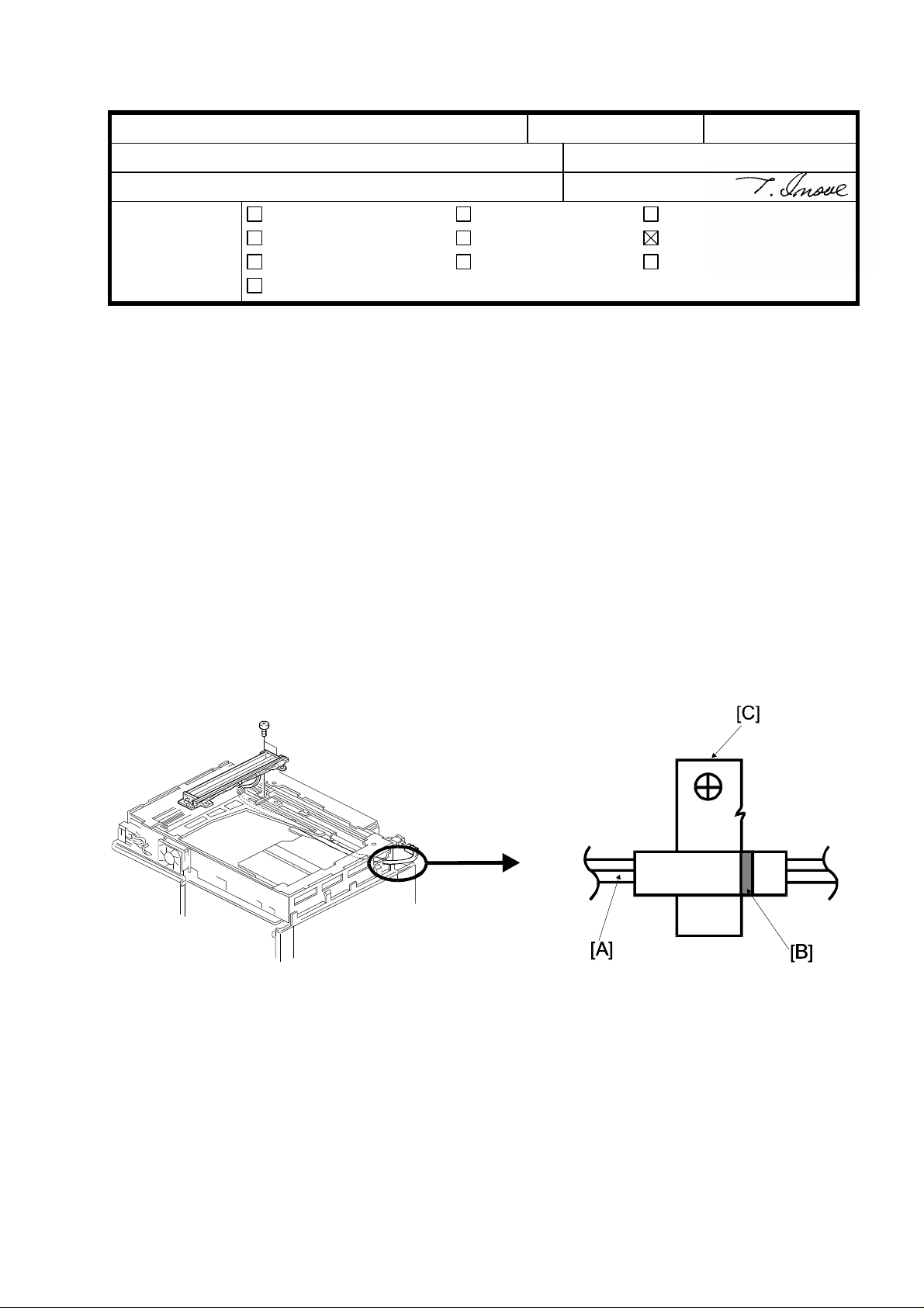
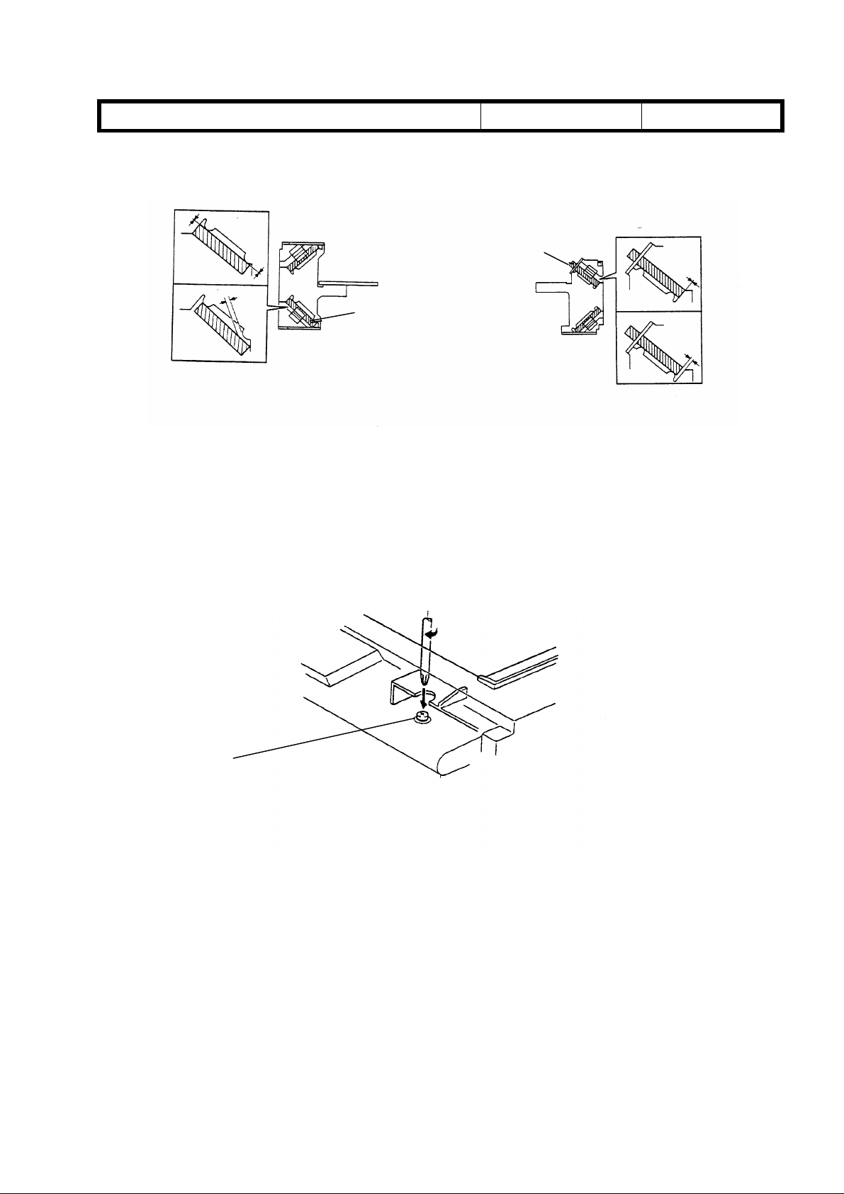
When reinstalling the 1st scanner, make sure to do the procedure described below. If it is
not performed, the scanner harness may fall from the 2nd scanner pulley, causing a
scanner lock condition.
NOTE: Clamp the scanner harness [A] at the position shown. The white paint mark [B]
should be aligned with the right side of the harness clamp [C].
Page 3

RICOH Technical B ulletin PAGE: 1/1
Model: Kingfisher Date: 30-Apr-97
No: 3
Subject: SC Code #14 Prepared by : M.Inohana
From: QAC 1st Field Information Dept. Checked by: T. Inoue
Classification:
Troubleshooting
Mechanical
Paper path
Other ( )
Part information
Electrical
Transmit/receive
Action required
Service manual revision
Retrofit information
The following description should be added to the “SERVICE CALL CONDITIONS” in the
Service Manual.
CODE #14 - ZERO CROSS SIGNAL ERROR 2
Definition
The detected current is not 50 or 60 Hz.
Possible Causes
• Defective main control board
• Defective ac drive/dc power supply board
• Zero cross line open
• CN101 on the main control board or CN207 on the ac drive/dc power supply board
is not correctly connected.
• Power line not stable
* Remedy for the initial production machines
• Turn the main switch off and on.
Page 4
RICOH Technical Bulletin PAGE: 1/1
Model: Kingfisher Date: 30-May-97
No: 4
Subject: Service Manual Revision Prepared by: M. Inohana
From: QAC 1st Field Information Dept. Checked by: T. Inoue
Classification:
Troubleshooting
Mechanical
Paper path
Other ( )
Part information
Electrical
Transmit/receive
Action required
Service manual revision
Retrofit information
1. Please correct your Service Manual as follows:
Page 4-20
Mode No. Function Settings
Auto Shut Off Selects the “Automatic Shut off” mode. 0: Yes
77 (Energy Star)
On/Off
The copier automatically shuts itself off at the auto
shut off time selected (SP14).
1: No
↓↓
Mode No. Function Settings
Auto Shut Off Selects the “Automatic Shut off” mode. 120V Machines
(Energy Star)
77
On/Off
The copier automatically shuts itself off at the auto
shut off time selected (SP14).
0: Yes
1:No
230V Machines
0: Yes
1: No
2. The following description should be added to the “SERVICE CALL CONDITIONS” in
the Service Manual.
CODE #96 - MAIN SWITCH ERROR
Definition
The machine does not turn off within 8.5 seconds after Auto Shut Off is performed.
Possible Causes
• Defective main switch.
• Connectors of the main switch are not correctly connected.
• Poor connection of the DC Harness of the main switch (some lines must be cut)
* Remedy for the initial production machines
• Turn the main switch off and on.
Page 5

RICOH Technical Bulletin PAGE: 1/3
Model: Kingfisher Date: 31-Jul-97
Subject: Troubleshooting of copy quality problems Prepared by: M.Inohana
From: QAC 1st Field Information Dept.
Classification:
This explains how to troubleshoot copy quality problems at machine installation. Problems
may arise during machine transportation. Use the following countermeasures when
problems occur in the field.
Troubleshooting
Mechanical
Paper path
Other ( )
Part information
Electrical
Transmit/receive
Action required
Service manual revision
Retrofit information
No: 5
Problems
1. The 1st Scanner is deformed or bent.
2. The 1st Scanner does not stay at the proper home position.
3. The Lens Unit moves to the wrong position and/or the lens locks and/or the lens does
not return to the home position.
4. Black copy or black band in the trailing area of copies.
(Cause: 3rd or 4th mirror moves to the wrong position )
5. Out of focus or poor sharpness on copies.
(Cause: 6th mirror angle in the wrong position )
6. Dirty background at the left side of copies.
(Cause: Abnormal condition of the optics unit and/or deformed main body )
Countermeasure for Transportation Damage at the Factory
1. 1st Scanner deformed or bent: Clamps will be added to the 1st Scanner
(from the August ’97 production machines onward).
2. The Lens Unit moves to the wrong position: A Lens Unit securing pin has been added
(from the end of July ’97 production machines onward).
3. The 3rd/4th Mirror moves to the wrong position: Double-sided tape has been added to
the back of the mirror and clamp area (from the end of May ’97 production machines
onward).
4. The 6th mirror angle varies: After adjustment of the angle, a screw lock has been
applied (from the end of May ’97 production machines onward).
5. Damage during transportation: 1 machine per pallet
(from the May ’97 production machines onward).
Page 6
RICOH Technical Bulletin PAGE: 2/3
Fig.1
Fig.2
Model: Kingfisher Date: 31-Jul-97
No: 5
Action required in the field
For the machines which cannot be treated as described above, the following action is
required.
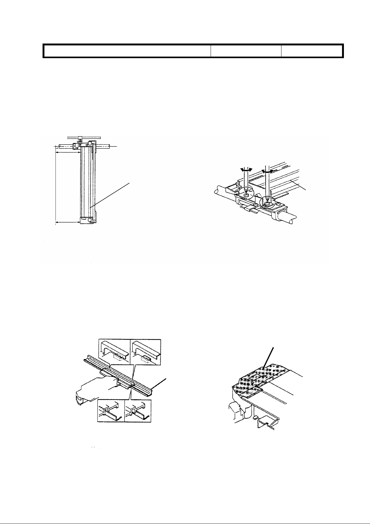
1) 1st Scanner deformed or bent
1st Scanner
1st Scanner
Cause : The front of the 1st Scanner is bent towards the right (Fig.1).
Action : Adjust the 1st scanner position (angle) as shown on page 6-7 of the Service
Manual (Fig.2).
2) Lens Unit moves to the wrong position, Lens Mylar out of position, Lens Unit locks.
Lens Mylar
Guide Rail
Fig.3
Fig.4
Page 7
RICOH Technical Bulletin PAGE: 3/3
4th Mirror
Model: kingfisher Date: 31-Jul-97
3). Black copy or black band at the trailing area of copies.
GOOD
3rd Mirror
NG
Fig.5
Cause : Incorrect positioning of the 3rd/4th mirrors (Fig.5,6)
Action : Re-position the 3rd/4th mirrors.
No: 5
GOOD
NG
Fig.6
4) Out of focus or poor sharpness on copies.
Adjustment Screw
Fig.7
Cause : The adjustment screw for the 6th mirror has loosened, resulting in an incorrect
mirror angle.
Action : (Fig.7)
1. Mark the original position of the adjustment screw.
2. Turn the adjustment screw clockwise approximately 45 degrees.
3. Check the copy quality.
4. Repeat steps 2 and 3 until the copy quality becomes satisfactory.
Page 8
RICOH Technical Bulletin PAGE: 1/2
15
15
14
Model: Kingfisher Date: 31-Jul-97
Subject: Peeling off of the Mylar Blade Prepared by: M. Inohana
From: QAC 2nd Field Information Dept.
Classification:
Troubleshooting
Mechanical
Paper path
Other ( )
Part information
Electrical
Transmit/receive
Action required
Service manual revision
Retrofit information
No: 6
SYMPTOM:
1. Image density decreases
2. The toner end indicator turns on when not in a toner end condition
CAUSE:
The mylar blades peel off, resulting in toner not being supplied properly. Then toner in the
development unit gets low even if there is toner in the bottle.
Mylar Blade
9
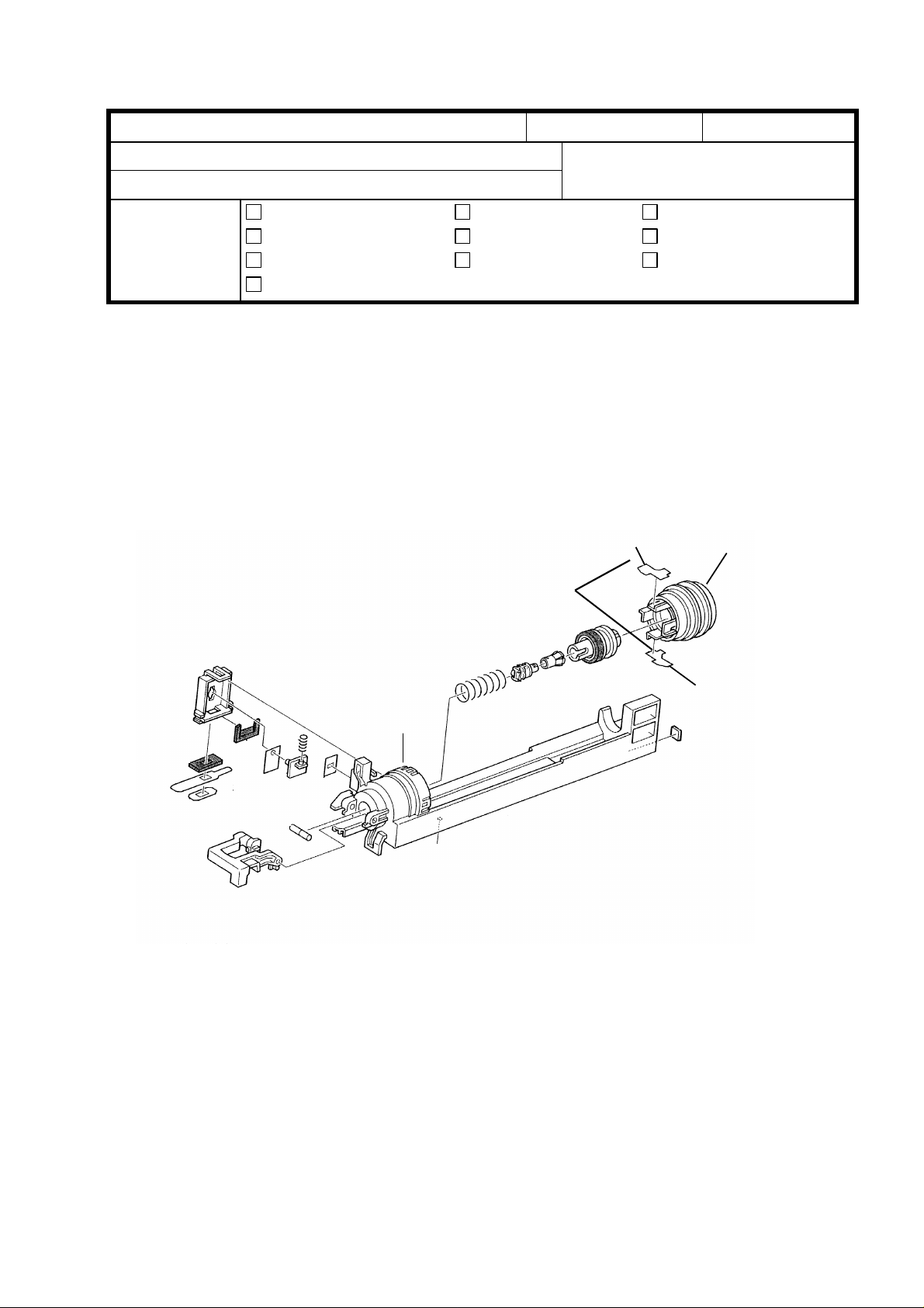
Action required:
1) Remove the toner bottle holder unit from the machine.
2) Remove the toner bottle cover [14] from the toner supply unit case [9]
3) Remove the Mylar Blades [15] which are peeling off.
4) Clean the area where the mylar blades should be attached.
5) Attach new mylar blades to the original position.
Page 9

RICOH Technical Bulletin PAGE: 2/2
Model: Kingfisher Date: 31-Jul-97
Countermeasure at the factory:
The following improvement has been applied to the May’97 production machines onward.
1) Clean and remove oily material at the area where the mylar blade should be attached.
2) Attach the mylar blade by pressing evenly.
No: 6
Page 10

T
Model:
Kingfisher
echnical
ulletin
B
Date:
15-Sep-97
No:
PAGE: 1/2
7
Subject:
From:
Classification:
Shock during shipment
QAC 1st Field Information Dept.
Troubleshooting
Mechanical
Paper path
Other ( )
Part information
Electrical
Transmit/receive
Prepared by:
Action required
Service manual revision
Retrofit information
T.Matsuno
Symptom
We have found that the first scanner went out of alignment, and the lens failed
before installation, during shipment in Europe and China.
Cause
It is assumed that since the Kingfisher is a lighter model, these units were handled more
roughly and as a result they were subjected to too much shock.
Countermeasure at the factory
The following improvement has been applied from the August ’97 production machines
onward.
1) Two scanner clamps (A2191851) were set beneath the scale to fix them
in the home position.
The setting position – 2 φ10mm holes on the scale.
2) A lens clamp (A2191850) was inserted into the φ3mm hole n the center
of the upper cover, so that lens carriage cannot be moved toward the
enlargement side.
(This means that the lens carriage will remain inside the lens cover.)
The purpose of both countermeasures is to make sure that the scanner and the lens
carriage are braced for shock during shipment before installation.
Page 11

T
Model:
Illustration
Kingfisher
Upper cover
Scale
echnical
Filament tape is attached so that the
lens clamp does not come off.
ulletin
B
Date:
15-Sep-97
No:
PAGE: 2/2
7
Tag
Scanner clamp
Filament tape
Filament tape is attached to prevent the
main switch from being pressed
before installation.
Page 12

T
Model:
Kingfisher (North America)
echnical
B
ulletin
Date:
15-Oct-97
No:
PAGE: 1/2
8
Subject:
From:
Classification:
Envelope for the NECR
QAC Field Information Dept.
Troubleshooting
Mechanical
Paper path
Other ( )
Part information
Electrical
Transmit/receive
Prepared by:
Action required
Service manual revision
Retrofit information
T.Matsuno
Action required in the field
Please delete #9. “ Envelope for NECR (-17 machines)” on page 3-3 in the Service
Manual for the Kingfisher.
- Service Manual -
Cross out
No.9
3 – 3
Page 13

T
Model:
Reason
The NECRs for the Kingfisher have, in most cases, already been sent by fax for the North
America markets (-17 machines) and are stored in the box with the other accessories.
Since it is unnecessary to have an envelope for the NECR among the accessories in the
box, we will delete this (#9. Envelope for NECR) from the Accessory Check for the
Kingfisher.
Kingfisher (North America)
echnical
B
ulletin
Date:
15-Oct-97
No:
PAGE: 2/2
8
Page 14

T
echnical
B
ulletin
RTB Correction
Reissue date:
The items with a line drawn through them have been deleted.
Model:
Kingfisher
15-Dec-97
Date:
15-Oct-97
No:
PAGE: 1/2
9
Subject:
From:
Classification:
To meet Energy Star requirements, the following modification has been applied to the
production machines.
Energy Star
QAC Field Information Dept.
Troubleshooting
Mechanical
Paper path
Other ( )
Part information
Electrical
Transmit/receive
Prepared by:
Action required
Service manual revision
Retrofit information
M.Inohana
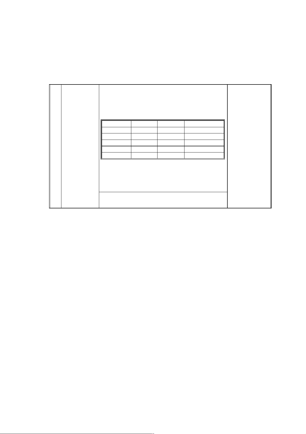
SP Mode
∗ Setting No.5 has been added.
Mode No. Function Settings
Auto Reset
Time Setting
(Energy Star)
14
Selects the auto shut off time.
The copier main switch is shut off automatically
after the selected auto shut off time, if SP77 and
UP10 are at “0”.
0:30 min. (Factory
Setting)
1 : 15 min.
2 : 60 min.
3 : 90 min.
4 : 120 min
∗ 5 : 240 min.
User Code
The following UPs have been added.
U-Code Function Settings
Auto Shut Off
On/Off
10
5 Exactly same as SP14 shown above.
Note: The factory settings of SP77 and UP10 for the USA version are 0:Yes.
For the other area versions, the factory settings are 1:No.
Selects the “Auto Shut Off” mode. 0 : Yes (Factory
Setting)
1 : No
Page 15

T
Model:
Kingfisher
echnical
B
ulletin
Date:
15-Oct-97
ROM Suffix Numbers applied to this modification
Part Number Model Area
A2195103D Kingfisher 110V,120V/60HZ area
A2195104D Kingfisher 220V,240V/50HZ,60HZ area
Cut-in Machine Serial Numbers
No:
PAGE: 2/2
9
A219 - 10 : AJ07870001
-15 : 7A47870001
-17 : A7367874569
-19 : A7367870001
-22 : AJ97870001
-26 : 3L78770001
-27 : A7367870401
-29 : A7367874998
-39 : A7367884548
-50 : AK17870001
-59 : A7367870301
-69 : A7367865221
∼
∼
∼
∼
∼
∼
∼
∼
∼
∼
∼
∼
Page 16

T
Model:
Kingfisher
echnical
B
ulletin
Date:
31-Oct-97
No:
PAGE: 1/1
10
Subject:
From:
Classification:
SYMPTOM:
CAUSE:
that discharged ions flow to the exposed area on the photoconductor and
re-charge it. Then, the electrical potential on the photoconductor surface
increases so that blurring is caused.
SOLUTION:
mylar has been attached to it so that discharged ions are blocked by the
longer casing and the mylar. Please see MB No.15 issued on October
31, 1997, for further information concerning this modification.
Blurred image
QAC Field Information Dept.
Troubleshooting
Mechanical
Paper path
Other ( )
Blurring appears on copies of low-contrast originals.
The gap between the charge corona casing and grid plate was too wide, so
One side of the corona casing shown below (∗) has been elongated and a
Part information
Electrical
Transmit/receive
Prepared by:
Action required
Service manual revision
Retrofit information
M.Inohana
Note:
than before.
Therefore adjust the exposure lamp value using SP48 (decrease by 3 ∼ 4 steps).
When the improved corona unit is installed in the copier, the image becomes lighter
∗
Page 17

T
Model:
Kingfisher
echnical
B
ulletin
Date:
15-Dec-97
No:
PAGE: 1/1
11
Subject:
From:
Classification:
The following information should be added to the SP mode section in the service manual.
A3/11"x17" Double Count Mode
QAC Field Information Dept.
Troubleshooting
Mechanical
Paper path
Other ( )
Part information
Electrical
Transmit/receive
Prepared by:
Action required
Service manual revision
Retrofit information
M.Inohana
SP Mode No. 27
Mode: A3/11”x17” Double Count
Function: Selects single or double count for the total counter with A3/11”x17” copies.
Double count is not applied for copies from the manual feed table.
0: Single (default)
1: Double
ROM: P/N A2195104C or newer versions
Cut-n Machine Serial Numbers
Code Serial Number
A219 – 10 AJ07810001
A219 – 15 7A47820001
A219 – 17 A7367813002
A219 – 19 A7367830001
A219 – 22 AJ97820001
A219 – 26 3L78270001
A219 – 27 A7367810177
A219 – 29 A7367821352
A219 – 59 A7367830151
Page 18

T
Model:
Kingfisher
echnical
B
ulletin
Date:
15-Mar-98
No:
PAGE: 1/2
12
Subject:
From:
Manual Correction
QAC Field Information Dept.
Classification:
Troubleshooting
Mechanical
Paper path
Other ( )
Part information
Electrical
Transmit/receive
Prepared by:
Action required
Service manual revision
Retrofit information
J. Kasamoto
Page 4-15
1. The description in the setting column for SP33 was incorrect. Correct as follows:
Old New
Settings Settings
0: Normal
1: Darker
2: Darkest
3: Lighter
4: Lightest
0: Normal
Darkest
1:
Darker
2:
3: Lighter
4: Lightest
→
2. Some descriptions for SP34 were incorrect. Correct as follows:
Old
Image Density
Adjustment
(ADS Mode)†
34
Selects the image density level in ADS mode.
The development bias and the exposure lamp
voltages are increased or decreased.
This adjustment affects copies made in ADS mode.
SP Setting Setting Dev. Bias Exposure Lamp
0Normal0 0
1 Lighter -40 V 0
2 Darker +40 V 0
3 Lightest -40 V +4 steps
4 Darkest +40 V -4 steps
The exposure lamp setting specifies the change
relative to the base exposure lamp voltage (Vo) in
SP48. 1 step of the lamp voltage equals 0.5 V for
120 V (NA), and 1.0 V for 230 V (EU) machines.
See “Detailed Descriptions - Development” f or more
details.
0: Normal
1: Light
2: Dark
3: Lighter
4: Darker
Page 19
T
New
echnical
↓
B
ulletin
PAGE: 2/2
34
NOTE:
Image Density
Adjustment
(ADS Mode)†
The items in bold italics have been corrected.
Selects the image density level in ADS mode.
The development bias and the exposure lamp
voltages are increased or decreased.
This adjustment affects copies made in ADS mode.
SP Setting Setting Dev. Bias Exposure Lamp
0Normal0 0
1
2
3 Lightest -40 V +4 steps
4 Darkest +40 V -4 steps
The exposure lamp setting specifies the change
relative to the base exposure lamp voltage (Vo) in
SP48, 1 step of the lamp voltage equals 0.5 V for
120 V (NA), and 1.0 V for 230 V (EU) machines.
See “Detailed Descriptions - Development” f or more
details.
Light
Dark
-40 V 0
+40 V 0
0: Normal
1: Light
2: Dark
3:
Lightest
Darkest
4:
Page 6-27
Please correct your service manual as follows:
5. Remove the optics cooling fan motor [A] (2 screws and 1 connector).
↓
5. Remove the optics
exhaust
fan motor [A] (2 screws and 1 connector).
Page 20

T
Model:
Kingfisher
echnical
B
ulletin
Date:
30-Apr-98
No:
PAGE: 1/2
13
Subject:
From:
Classification:
Double feed from the paper tray
QAC Field Information Dept.
Troubleshooting
Mechanical
Paper path
Other ( )
Part information
Electrical
Transmit/receive
Prepared by:
Action required
Service manual revision
Retrofit information
M.Inohana
SYMPTOM
Double feeds occur when copies are made (especially with A-sized paper).
CAUSE
1. The friction coefficient of the paper is higher than that for which the machine was
designed. (Paper problem)
2. The paper is poorly cut so the sheets stick together and hinder paper separation.
(Paper problem)
3. The side fence in the paper tray is not set flush against the paper so the paper gets
caught on the paper guide and this hinders paper separation. (Paper setting problem)
SOLUTION
If double feeds occur in the field, please use the measures listed below.
1. Change the position of the paper feed roller and the paper feed guide to match the Asized paper. (Please refer to page 6-31 in the Service Manual)
Be sure to adjust the positions of both the paper feed roller and the paper guide.
2. Please pay attention to the instructions provided for setting the paper or the paper tray.
(Decal: A2192692)
(1) Set the paper correctly in the paper tray. (Align the edges of the paper)
(2) When adjusting the side fences, make sure that there are no gaps between the side
fences and the paper. (If gaps exist, the function of the side fences is reduced)
(3) When setting the paper tray, do not apply a lot of force, do it gently. (If the tray is
set with a lot of force, the paper will shift towards the back of the tray.)
3. If the customer has difficulty following the instructions listed above, get the permission
of the customer and secure the side fences in place with screws.
Procedure for securing the side fences
Set a few sheets in the tray, align the side fences so that they are flush against the
paper, and then secure the fences in that position with screws.
(Screws: M3X8 tapping screw: 04130082B)
If the measures listed above do not solve the problem, please try the following.
Replace the paper feed roller with the Double-feed countermeasure feed roller.
(A2192555: Paper feed roller)
Note: The modified roller has been implemented in the mass-production machines starting
from the April 1998 production run.
Page 21

T
Model:
Details of the Modification
1. Paper feed roller modified. (The difference in shape is shown below)
2. The setting positions of the paper feed roller and the paper guide have been adjusted
Kingfisher
to suit A-sized paper.
- OLD -
echnical
B
ulletin
Date:
30-Apr-98
No:
PAGE: 2/2
13
- NEW -
Slight Protrusion
Page 22

Technical
Bulletin
PAGE: 1/1
Model:
Subject:
From:
Kingfisher
Service Manual Correction
Technical Service Dept., GTS Division
Classification:
Troubleshooting
Mechanical
Paper path
Other ( )
Part information
Electrical
Transmit/receive
Date:
30-Jun-99
Prepared by:
No.:
M. Ishihara
Action required
Service manual revision
Retrofit information
Page 4-18
The default of SP54: 149 was printed in correctly. The correct default is 102
Incorrect
54 TD Sensor
Gain
Adjustment
When the TD Sensor initial setting is performed,
this mode is adjusted automatically
.
Normally, this value should not be changed.
0 255
Default =
(0.04 V per step
RA219014
149
Correct
54 TD Sensor
Gain
Adjustment
When the TD Sensor initial setting is
performed, this mode is adjusted
automatically.
0 255
Default =
102
(0.04 V per step)
Normally, this value should not be changed.
SP54 is used at the factory when test copies are made during the machine assembly
process. It should not be used in the field.
Page 23

T
echnical
B
ulletin
PAGE: 1/1
Model:
Subject:
From:
Classification:
Kingfisher/Grand Kingfisher/Tequila
Toner drops onto the copy
Technical Service Dept., GTS Division
Troubleshooting
Mechanical
Paper path
Other ( )
Part information
Electrical
Transmit/receive
Date:
31-Aug-99
Prepared by:
No.:
RA219015
M.Ishihara
Action required
Service manual revision
Retrofit information
SYMPTOM
1. Toner drops onto the copy.
2. Dirty background on copies (Occasional)
3. Image density too high (Occasional)
CAUSE
1. Too much toner is supplied to the development tank due to misdetection by the toner
density sensor.
2. Used toner accumulates in the IU (Imaging Unit), preventing proper recycling.
ACTION REQUIRED
Please follow the procedure as shown below.
1. Remove the IU from the machine.
2. Completely remove the recycled toner in the toner collection coil and the toner recycling
belt area.
3. Install the IU in the machine.
4. Remove the toner bottle from the machine.
5. Make 20, A4 sideways, skyshot copies (solid black copies).
6. Set an original and make some copies to confirm that copy quality is normal.
7. Change the toner supply mode from “0” to “1” using SP30.
8. Make some copies while monitoring the TD sensor output (SP55).
9. Input the value obtained in step 8 in SP53 – TD Sensor Target Control Voltage
Adjustment.
10. Install the toner bottle in the machine.
11. Set an original and make some copies to confirm that copy quality is normal.
Note:
When the developer is replaced, please observe the following for efficient troubleshooting:
1) Do SP66.
2) Do not change the settings of SP30 and SP53. (SP30 must be at “1”. TD
Sensor control voltage must be kept at the same level in SP53, as entered in step
9 above.)
Page 24

RICOH Technical
Bulletin
PAGE: 1/4
Model:
Subject:
From:
Kingfisher
Toner drops onto the copy
Technical Service Dept., GTS Division
Classification:
Troubleshooting
Mechanical
Paper path
Other ( )
Date:
Prepared by:
Part information
Electrical
Transmit/receive
22-Sep-99
Action required
Service manual revision
Retrofit information
No.:
M. Ishihara
RA219016
SYMPTOM
1. Toner drops onto the copy.
2. Dirty background on copies (Occasional)
3. Image density too high (Occasional)
CAUSE
Although the toner concentration in the developer is maintained between 3 and 4%,
an increase can be observed when used over an extended period of time. This level
is normally kept under 5% even after 60K copies, however there are rare cases where this
limit is exceeded due to the environmental factors described below. These are thought to
cause the toner to fall onto the surface of the copy.
1. The presence of paper dust as well as conditions such as high humidity are thought to
cause an oversupply of toner to the development unit (by raising the limit of the toner
concentration control to over 6%), which in turn causes the toner to fall onto the copy
surface.
Too much toner
4%
3%
Controlled Limit
Toner
Consent
-ration
0 20K 60K40K
Copy Volume
6%
5%
4%
2. In addition, due to this oversupply of toner to the development unit, recycled toner
creates a blockage in the imaging unit and the toner falls from the cleaning area.
Page 25

RICOH Technical
Bulletin
PAGE: 2/4
Model:
Kingfisher
Date:
22-Sep-99
No.:
RA219016
ACTION REQUIRED
A. Countermeasure in the field:
Please follow the procedure as shown below if the toner dropping problem occurs in the
field.
1. Remove the IU from the machine.
2. Completely remove the recycled toner at the toner collection coil under the cleaning
blade and the toner recycling belt area. Install the IU in the machine.
3. Remove the toner bottle from the machine. Check that SP38 is 0. (Input "0" if it is not.)
4. Make 20, A4 sideways, skyshot copies (Black solid copies).
5. Set an original and make some copies to confirm that copy quality is normal.
6. Change the toner supply mode from “0” to “1” using SP30.
7. Make some copies while monitoring the TD sensor output (SP55).
8. Input the value obtained in step 7 into SP53 – TD Sensor Target Control Voltage
Adjustment. (If it is more than 127, input 127.)
9. Install the toner bottle in the machine.
10.Set an original and make some copies to confirm that copy quality is normal.
Note:
When the developer is replaced, please observe the following for efficient troubleshooting:
1) Perform the SP66 to initialize the developer .
2) Do not change the settings of SP30 and SP53. (SP30 must be at “1”. TD sensor control
voltage must be kept at the same level in SP53, as entered in step 8 above.)
B. Permanent Countermeasure:
This rise in the amount of toner being supplied will be prevented as determined by the
copy volume by modifying the software so that an oversupply does not result.
For the
machine of mass production. It is scheduled to be implemented in the
October 1999 mass production.
Kingfisher2
4%
Toner
Density
, this modification is scheduled to be implemented from the first
Kingfisher
5%
4%
0 20K 60K40K
from
Page 26

RICOH Technical
Bulletin
PAGE: 3/4
Model:
If the above symptom should occur in the field before preventative maintenance is
performed, please institute the temporary countermeasure described in the previous
section (A.) and refrain from upgrading the software.
The new software has two major differences from the previous version:
The overall process control and toner density control (maintained by lowering
it to a fixed value every 1K). Due to these differences, it is recommended that
the new firmware be used together with new developer.
NOTE:
Please upgrade the software at the next PM visit (when the developer is replaced).
Please refer to the flow chart on the following page.
(Note: When the developer is replaced, remove the old developer completely. Otherwise
the volume of the developer is increased and it causes the toner to drop.)
Kingfisher
Date:
22-Sep-99
No.:
RA219016
Page 27

RICOH Technical
Bulletin
PAGE: 4/4
Model:
Kingfisher
Date:
22-Sep-99
FLOW CHART FOR THE TONER DROPPING PROBLEM
START
Remove the Imaging Unit from the machine.
Remove the recycled toner in cleaning unit
(under the cleaning blade) and at the recycling belt area.
YES
To remove
excessive
toner from the
developing unit
Is PM required?
NO
Install the imaging Unit.
Remove the toner bottle from the machine.
Input "0" in SP38 if it is not.
Make 20(A4 sideways) skyshot copies to
confirm that copy quality is normal.
Set an original and make some copies to
confirm that the copy quality is normal.
Replace the developer in the imaging Unit.
Note: Completely remove the developer
from the imaging unit.
(Otherwise the amout of developer will
increase causing toner recycling process
not function properly.
Install the imaging Unit.
Replace the ROM.
Perform the toner initialization
(SP66).
If the SP30 is "1", set it to "0".
No.:
RA219016
To maintain
proper toner
density
NO
Change the toner supply mode from "0" to "1" (in the SP30).
Make several copies while monitoring the TD sensor output (SP55).
Input the value obtained in the previous step into SP53 - TD Sensor
Target Control VoltageAdjustment.
Install the toner bottle in the machine.
Set an original and make several copies to confirm that copy quality
is normal.
Is Image density
normal?
YES
END!
 Loading...