

Page 1
FT3320
FIELD SERVICE MANUAL
ICOH COMPANY, LTD.
Page 2
INSTALLATION
1
.
2
3
4
5
Table of Contents
SERVICE TABLES
REPLACEMENT AND ADJUSTMENT
Page 3
Page 4
Page 5

VINYL ENVELOPE
POINT-TO-POINT
ELECTRICAL COMPONENT AND CONNECTOR LAYOUTS
TABLE OF ADJUSTMENTS
SERVICE TABLES
●
Page 6

Q
SECTION 1
INSTALLATION
Page 7
INSTALLATION
5-1 SHORT HAUL TRANSPORTATION .............................1-14
5-2 LONG HAUL TRANSPORTATION BY VEHICLE ..... ...1-14
Page 8

1. INSTALLATION REQUIREMENTS
1-1 ENVIRONMENT
1 NOV. ’87
1. Temperature Range:
2. Humidity Range:
3. Ambient Illumination:
10*C to 30°C (50°F to 86°F)
15% to 90% RH
Less than 1,500 Iux (Do not expose to direct
sunlight.)
4. Ventilation:
5. Ambient Dust: Less than 0.15 mg/m
6. Room Size:
Room air should turn over at least 3 times/hour.
3
(4 x 10
-3
oz/yd3)
More than 10 m3 (13.4 yd3)
7. If the installation place is air-conditioned or heated, place the machine:
Where it will not be subjected to sudden temperature changes.
●
Where it will not be directly exposed to cool air from an air conditioner
●
in the summer.
Where it will not be directly exposed to reflected heat from a space
●
heater in winter.
8. Avoid placing the copier in an area filled with corrosive gas.
9. Avoid any areas higher than 2,000 meters (6,500 feet) above sea level.
10. Place the copier on a strong and level base.
11. Avoid any areas where the copier may be subjected to frequent strong
vibration.
1-1
,.
Page 9
1 Nov. ’87
1-2 MACHINE LEVEL
1. Front to back: Within 5 mm (0.2”) of level.
2. Right to left: Within 5 mm (0.2”) of level.
Set a carpenter’s level on the exposure glass to check the machine level.
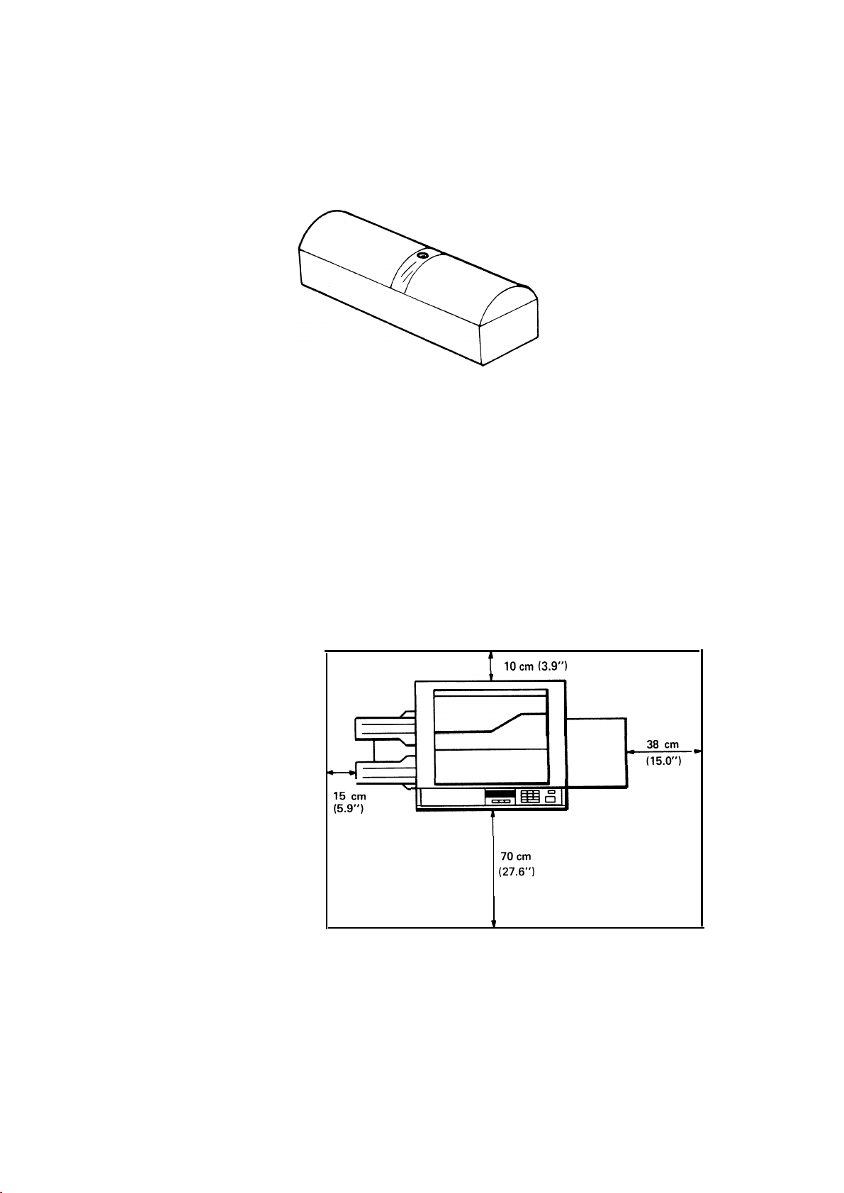
1-3 MINIMUM SPACE REQUIREMENTS
1. Front :70 cm (27.6”).
2. Back :10 cm (3.9”).
3. Right :38 cm (31 .5”).
4. Left
:15 cm (3.9”).
1=2
Page 10
1 Nov. ’87
1-4
POWER REQUIREMENTS
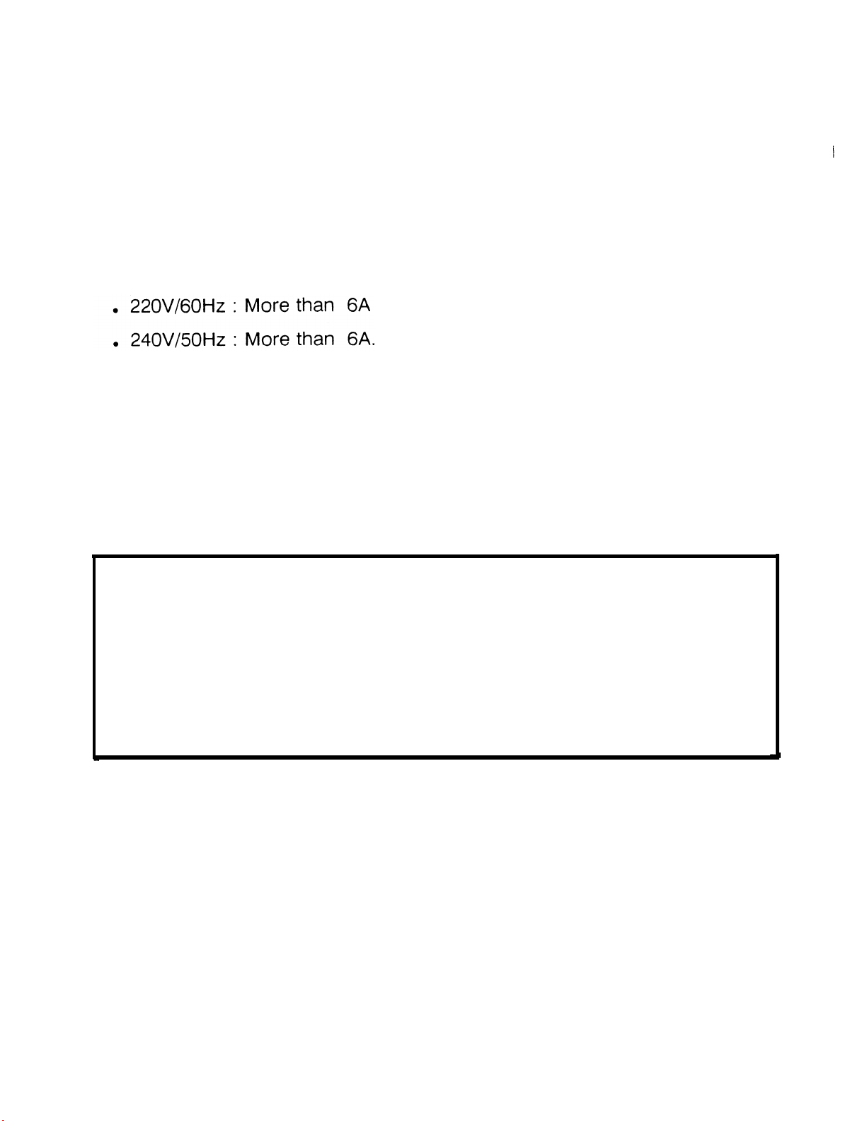
1. Input voltage level:
• 110V/60Hz : More than 12A
ž115V/60Hz : More than 12A
220V/50Hz : More than 6A
•
2. Permissible voltage fluctuation: 10%.
3. Permissible extension
cord:
At least 300V, 30A capacity and less than 5
meters (16.4 ft) long.
Be sure to ground the machine.
(Do not connect the grounding wire
to a gas pipe.)
Make sure the plug is firmly inserted in the outlet.
Avoid multi-wiring.
Do not set anything on the power cord.
Page 11

1 Nov. ’87
1-5 ACCESSORY CHECK
Check the accessories and their quantities according to the following list:
Cassette
Copy Tray
Drum
Operating Instructions
NECR
Envelope for NECR (1 15V only)
Multi-lingual Decal (220/240V only)
Paper Size Decal
1 pc
1 pc
1 pc
1 pc
1 pc
1 pc
1 pc
1 pc.
Page 12
2. COPIER INSTALLATION
1 Nov. '87
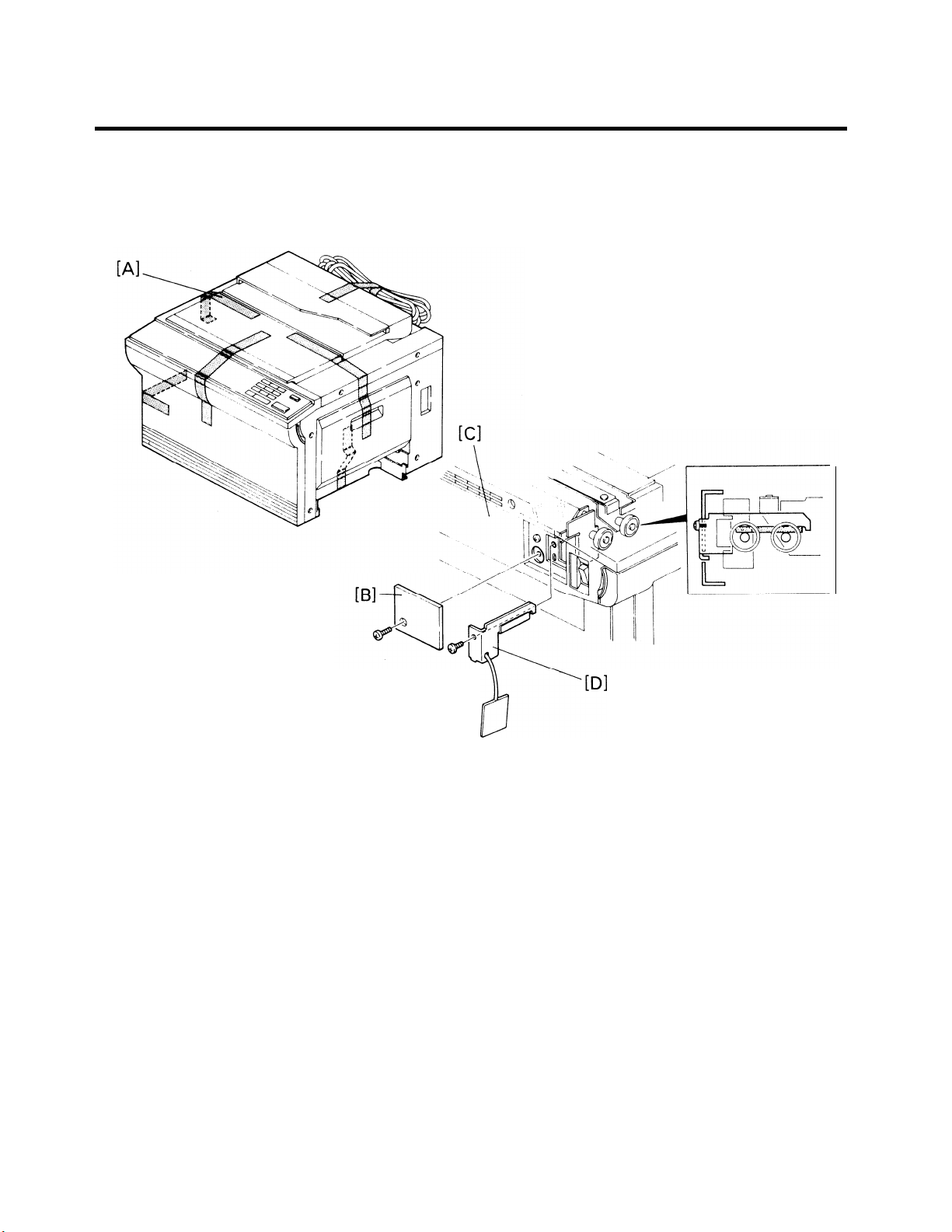
1. Remove the 6 strips of shipping tape [A].
2. Remove the lock plate cover [B] from the left cover [C] (1 screw).
3. Remove the scanner lock plate [D] (1 screw).
4. Re-install the lock plate cover.
Page 13
1 NOV. ’87
NOTE: When the transport lock plate is removed, the transport unit may fall
and be damaged; to prevent this, gently lower the transport unit
using the transport release lever [B].
6. Remove the development retainer plate [C] from the drum stay [D] (1
screw).
7. Raise the development lock lever [E] and pull out the development unit
[F]
●
1-6
Page 14
8. Remove
screw).
the charge corona unit [A] together with the wire cleaner [B] ( 1
9. Place a sheet of paper [C] over the
T/S
corona unit [D].
10. Remove the drum stay [E] (1 screw and 1 knob).
NOTE:
11
12
13.
The drum stay knob is reverse threaded.
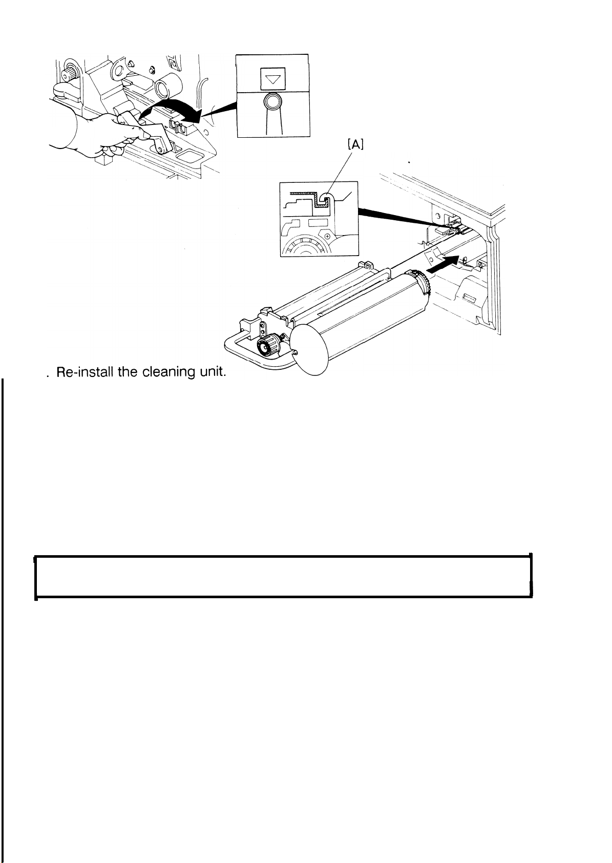
Remove the drum flange [F], and the cleaning unit [G].
.
w
Open the exit cover [H].
Remove the fusing cover
[1] from the inside of the copier ( 2 screws).
1-7
Page 15
1 Nov. ’87
I
14
●
Remove the oil supply pad [A].
Prime the oil supply pad with silicone oil [B].
15
●
16
.
Re-instaH the oil supply pad.
i
NOTE: Two notches of the oil supply pad must rest on the two hooks, The
tail of the oil supply pad must be in the oil sump.
17
.
Re-install the fusing cover and close the exit cover.
18
.
Turn the mouth of the silicone oil tank [C] to the front.
19
.
Remove the silicone oil tank cap [D] and pour silicone oil into the tank.
Replace the silicone oil tank cap and
20
.
tion.
NOTE: Clean up any oil that was spilt.
turn the mouth to its original posi-
1-8
Page 16
[A]
I
1 Nov. ’87
.
21
Separate the toner tank [A] from the development unit [B] (2 screws).
.
22
Pour one pack of developer (Developer Type 3300) [C] into the development unit while turning the knob [D] counterclockwise to distribute the
developer.
.
Remount the toner tank on the development unit.
23
.
24
Dust the drum, the cleaning blade, and the cleaning brush with setting
powder [E].
25
●
Pull out the drum guide [F] and insert the drum [G].
Push in the drum guide and set the drum flange.
26
1-9
Page 17
1 Nov. ’87
27
NOTE: When inserting
face.
+
28. Set the drum stay
the cleaning unit, keep it away from the drum sur-
and the charge corona unit complete
with the wire
cleaner.
29. Remove the paper
over the T/S corona unit and return
the transport
release lever until the roller is positioned under the arrow.
To prevent the drum from being damaged, do not raise the transport
unit without setting the drum stay.
30. Re-install the development unit and secure it using the development
retainer plate.
NOTE: When installing the development unit, be sure that the development
unit rail [A] is properly engaged with the unit guide rail on the
copier, but keep it away from the drum surface.
1“10
Page 18
[B]
.
1 Nov. ’87
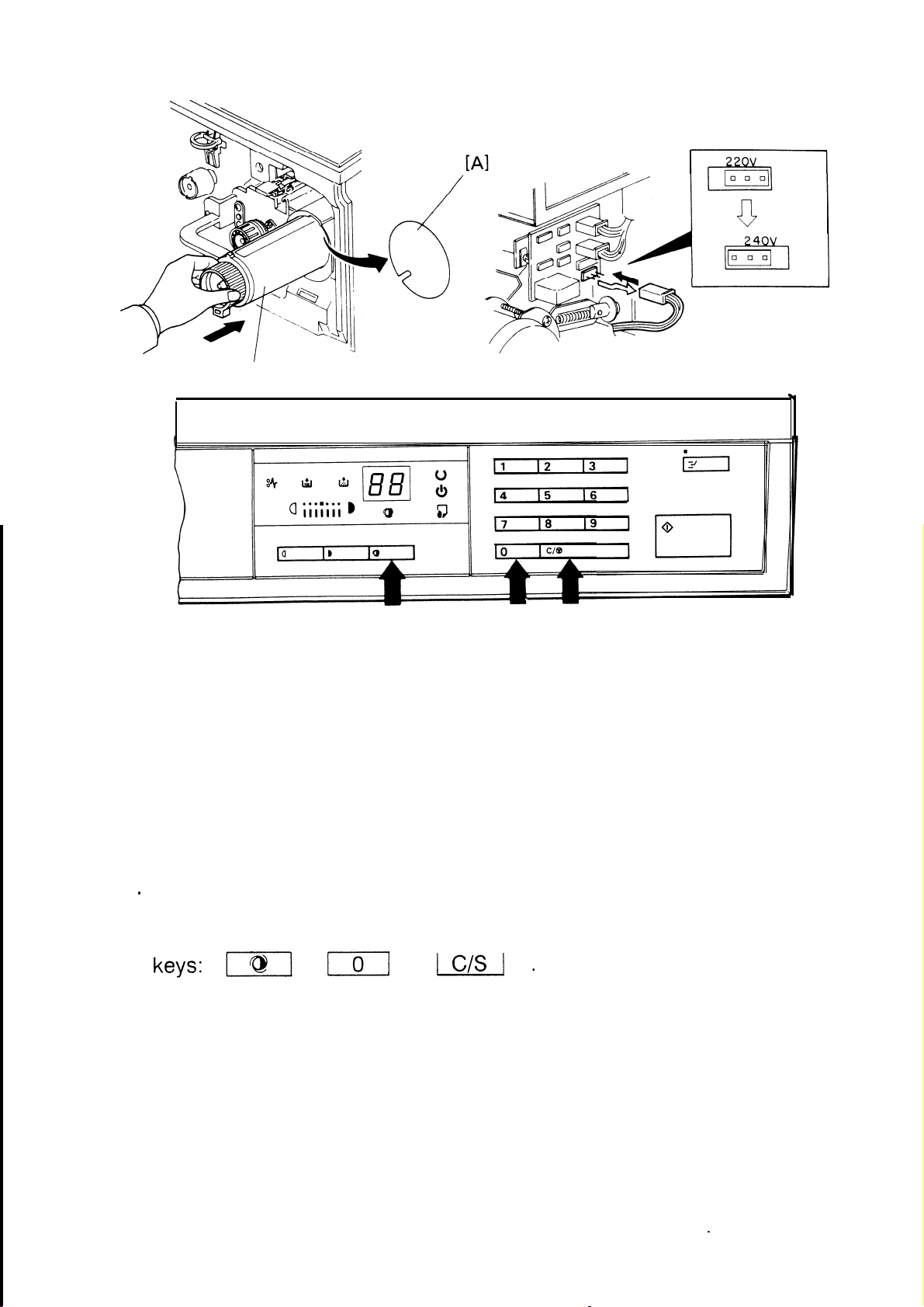
31. Remove the toner hopper seaI [A], then install one toner cartridge [B].
NOTE: Refer to the decal on the machine or the Operating Instructions for
the toner supply procedure.
32
.
For 240-volt areas, remove the rear cover (2 screws) and reposition the
220/240 -voIt connector on the ac drive board.
Load paper in the cassette, then set the cassette and the copy tray.
9
33.
.
Plug in the copier and turn on the main switch while pressing the
34
This causes the toner agitator to
rotate, filling the toner hopper with toner.
●
Check the machine operation and the copy quality,
35
●
Fill out the New Equipment Condition Report.
36
1-11
.
Page 19
.
1 Nov. ’87
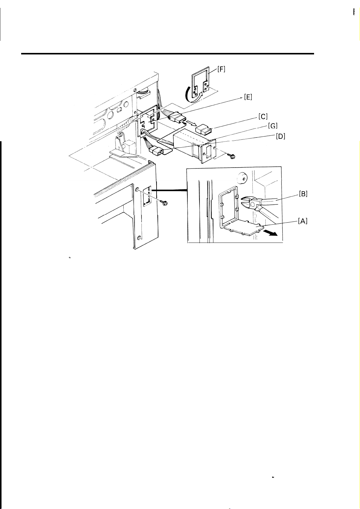
3. KEY COUNTER HOLDER INSTALLATION
[
●
Remove the rear and right covers.
1
s
●
Cut out the key counter access hole section [A] with nippers [B].
2
●
Remove the shorting plug [C] from the key counter connector (4p).
3
4
.
Connect the connector [D] (4p) of the key counter holder to the key
counter harness through the access hole [E].
.
Hold the fixing plate [F] on the inside of the key counter bracket and in-
5
sert the key counter holder [G].
.
Align the holes on the fixing plate with the mounting holes of the key
6
counter holder and secure the holder.
NOTE: The fixing plate has three sets of holes. When installing, make sure
to use the correct holes that match the type of counter.
7. Re-install the covers.
0
1-12
Page 20
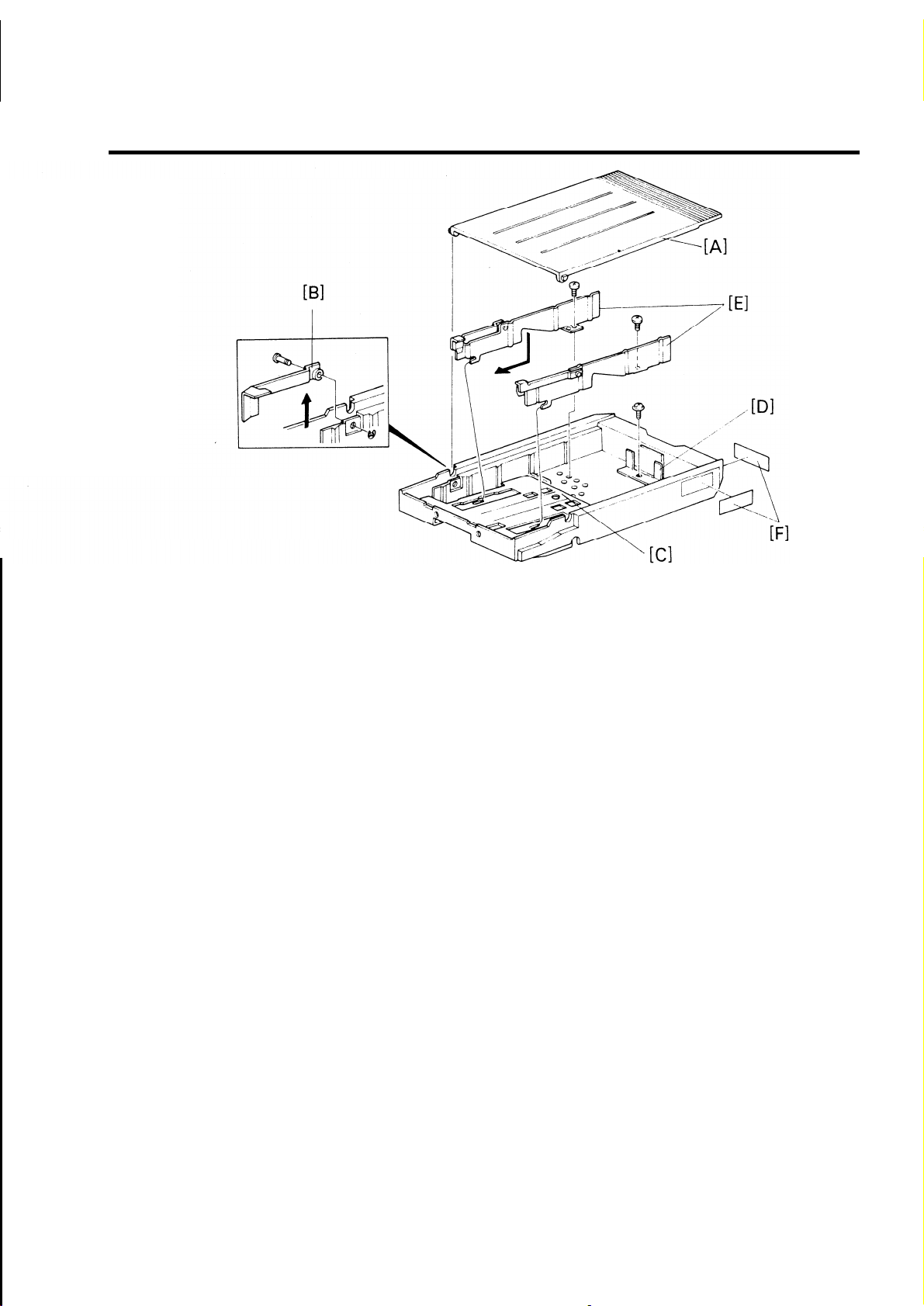
4. CASSETTE MODIFICATION
I
1 Nov. ’87
1
●
Remove the cassette cover [A].
2. Remove the arm pins (1 “E” ring each) and lift out the side fence arms
[B]
..
NOTE: Keep these parts for future use.
3. Remove the bottom plate [C].
4. Fit the rear fence [D] (1 screw), side fences [E] (1 screw each), and re-
install the bottom plate.
NOTE: The paper size positions are shown on the inside of the cassette.
5. Attach the appropriate paper size decals [F] to the cassette as shown.
The part numbers for the above parts are as follows:
ITEM
Rear fence
Right side fence
Left side fence
Screws (3 pcs.)
PART NUMBER
54472941
A0082727
52152716
09644010W
-
1-13
Page 21
.
.
1 Nov. ’87
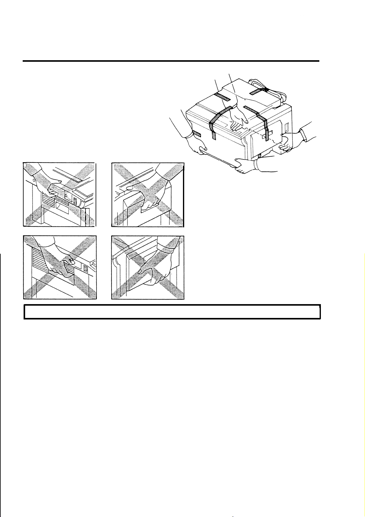
5. TRANSPORTING THE COPIER
Always hold the copier at the correct places (see illustration).
The copier may be seriously damaged
if it is moved without the following
preparation:
5-1 SHORT HAUL TRANSPORTATION
1.
Remove the copy tray and the cassette.
2. Secure the following items with tape:
manual
a)
platen cover
b)
front cover
c)
d)
exit cover
e)
power supply cord (roll
feed table
up first).
1-14
Page 22
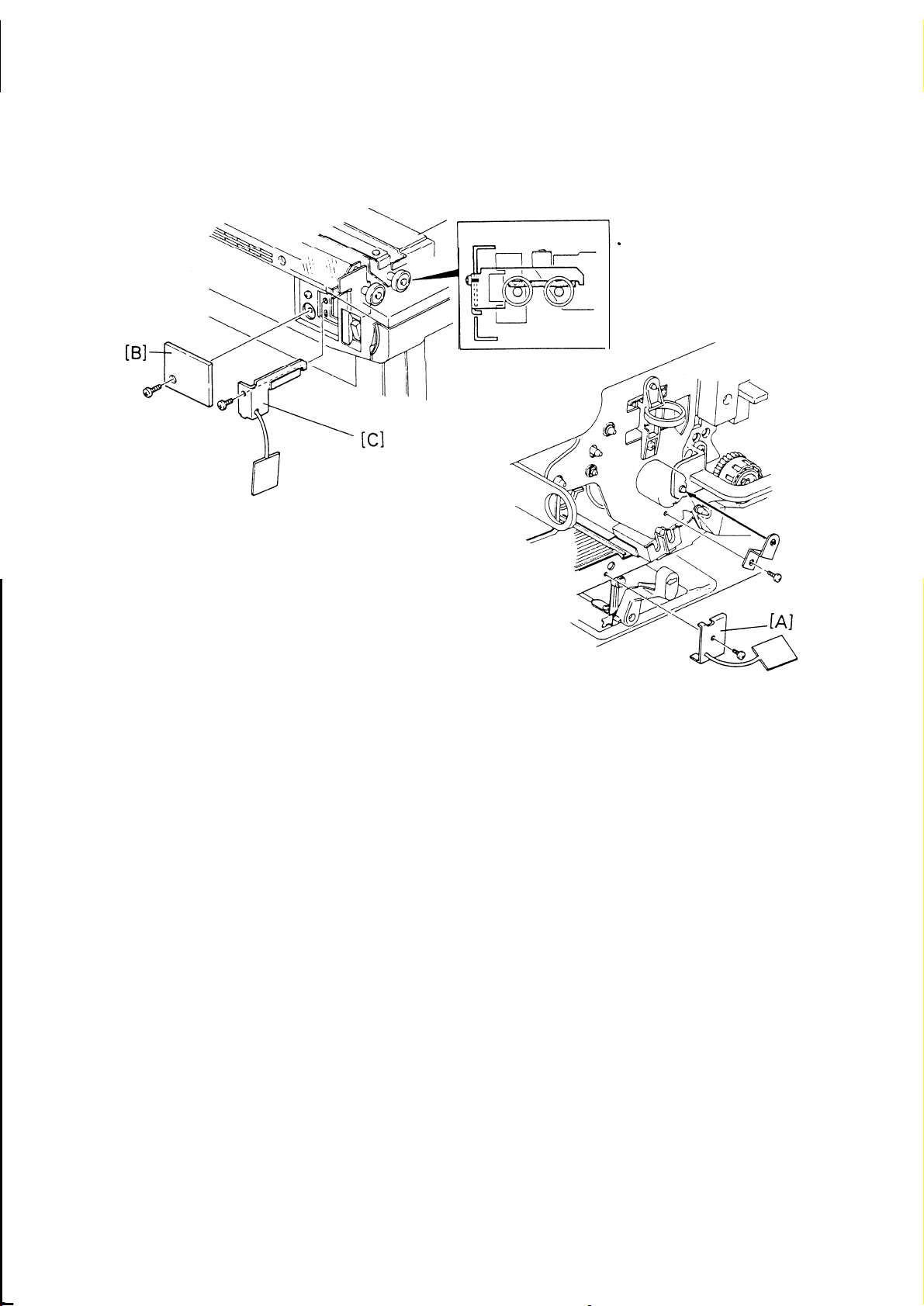
5-2 LONG HAUL TRANSPORTATION BY VEHICLE
9
1 Nov. ’87
1. Remove the developer (see 2-1 Developer Replacement).
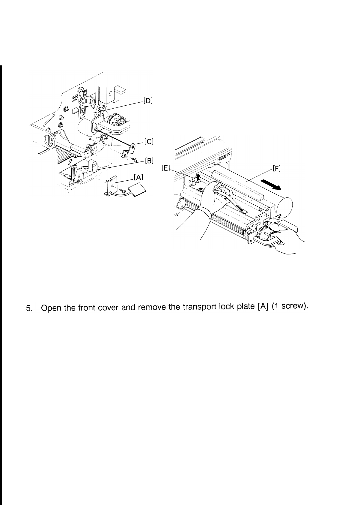
2. Install the transport lock plate [A] (1 screw).
3. Temporarily remove the lock plate cover [B] (1 screw) and fit the scanner lock plate [C] (1 screw), and re-install the lock plate cover.
NOTE: The scanner should be in the home
position before this
procedure
is made.
4. Perform procedures 1. and 2. of the Short
Haul Transportation
1-15
Page 23

SECTION 2
SERVICE TABLES
Page 24
SERVICE
TABLES
Page 25

1. PM TABLE
1 Nov. ’87
1: Inspect L: Lubricate
ITEM
OPTICS
1.
Platen cover
sheet
2. Exposure
glass
3.
Lens, mirrors,
reflector,
toner shield
glass
4. Original ID
sensor
5. Exposure lamp
6. Reverse
clutch damper
7 Guide rod and
EM 40K
c c c c c
c
c
c
R: Replace A: Adjust C: Clean
80K 120K
c c
c c
c
c c
160K
c
c
I
I
c
Water (replace if
necessary)
Water or alcohol
Silicone cloth or
blower brush
Blower brush
Replace if necessary
Check for damage.
Replace if necessary
Alcohol
NOTES
guide plate
8. Guide rod felt
AROUND DRUM
1.
Corona wires
2. End blocks
and casings
3. Corona paper
guide
4. Transfer
entrance mylar
5. Quenching
Lamp
6. Pre-Transfer
Lamp
7. ID sensor,
L
I
c c
c
c
c
c
c c
c c c
c c
c c
c c c
c c
I
R
c
I
c
c
c
c
c
c
I
R
c
c
c
c
c
c
Launa oil
Blower brush or dry
cloth
Blower brush or dry
cloth
Blower brush or
cloth (alcohol)
Blower brush or
cloth (alcohol)
Blower brush or dry
cloth
Blower brush or dry
cloth
Blower brush
Drum thermis-
tor
2-1
Page 26
1 Nov. ’87
I
I: Inspect L: Lubricate
ITEM
PAPER FEED
1.
Pickup roller
2. Registration
rollers
3. Cassette Bottom Plate Pad
4. Paper feed
guide plates,
transport
guide plates,
and other
guide plates
5. Transport belt
6. Feed and
reverse rollers
7. Pick-off pawls
8. Torque limiter
EM
c
R: Replace A: Adjust C: Clean
40K
I
80K
I
120K
I I
c
C
c
c
c
c
c
R
c
c
160K
c
c
c
c
R
c
L
L
NOTES
Cloth (water),
replace if necessary
Cloth (water)
Cloth (water)
Cloth (water)
Cloth (water)
Replace if necessary
Mobil Temp 78,
clean before lubricate
9. Exit rollers
10. Paper feed
clutch
‘FUSING UNIT
1.
Hot roller
2. Pressure roller
3. Fusing ther-
mister/ thermoswitch
4. Hot roller
strippers
5. Oil supply pad
6. Fusing
entrance and
exit guides
7. Silicone oil
tank
c
c
c
L
R
C
R
c
I“
I
I
I
I
c
L
R
c
R
R
c
I
Alcohol or water
Mobil Temp 78,
clean before lubricate
Dry cloth
Refill if less than half
full
2“2
Page 27
1 Nov. ’87
I
I: Inspect L: Lubricate
ITEM
8.
Oil Blade
DEVELOPMENT
1.
Developer
2. Toner scattering prevention
seal
3. Side seals
4.
Development
unit guide
CLEANING
1.
Cleaning blade
2. Cleaning brush
EM 40K
C
R: Replace A: Adjust C: Clean
80K 120K
I
I I
c
R
I
R
R
I
I
c c
R
R
I I
R R
I
160K
R
R
I
c
R
If necessary
Clean off paper dust
and other dirt
Clean with soft cloth
when replacing
developer
Dust with setting
powder
When replacing,
clean inside the unit
and dust the brush
with setting powder
I
T
NOTES
3. Cleaning seal
4. Cleaning unit
5. Used toner
tank
OTHERS
1.
Exit sensor
2. Rear cover filter
3. Drive belt
4. Bearings
5. Drive gears
6. Antistatic
brush
I
I
c
I
c
I
I
I
c
I I
I
1
I
I
I
I I
I
c c
I
I
I
I
I
I
I
I
Replace if dirty
Replace if toner over”
flow is detected
Check the feeler ac-
tion
Clean or replace if
necessary
Adjust if deformed
2-3
Page 28

1 Nov. ’87
2. GENERAL SERVICE TABLES
Test Points
2-1
Number
TPI02
TPI03
TPI04
-
22
Variable Resistors
Number Function
VR101
VR102
Function
Original ID sensor voltage
GND
image density sensor voltage
Adjusts the original ID sensor voltage
Adjusts the image density sensor voltage
2-4
Page 29
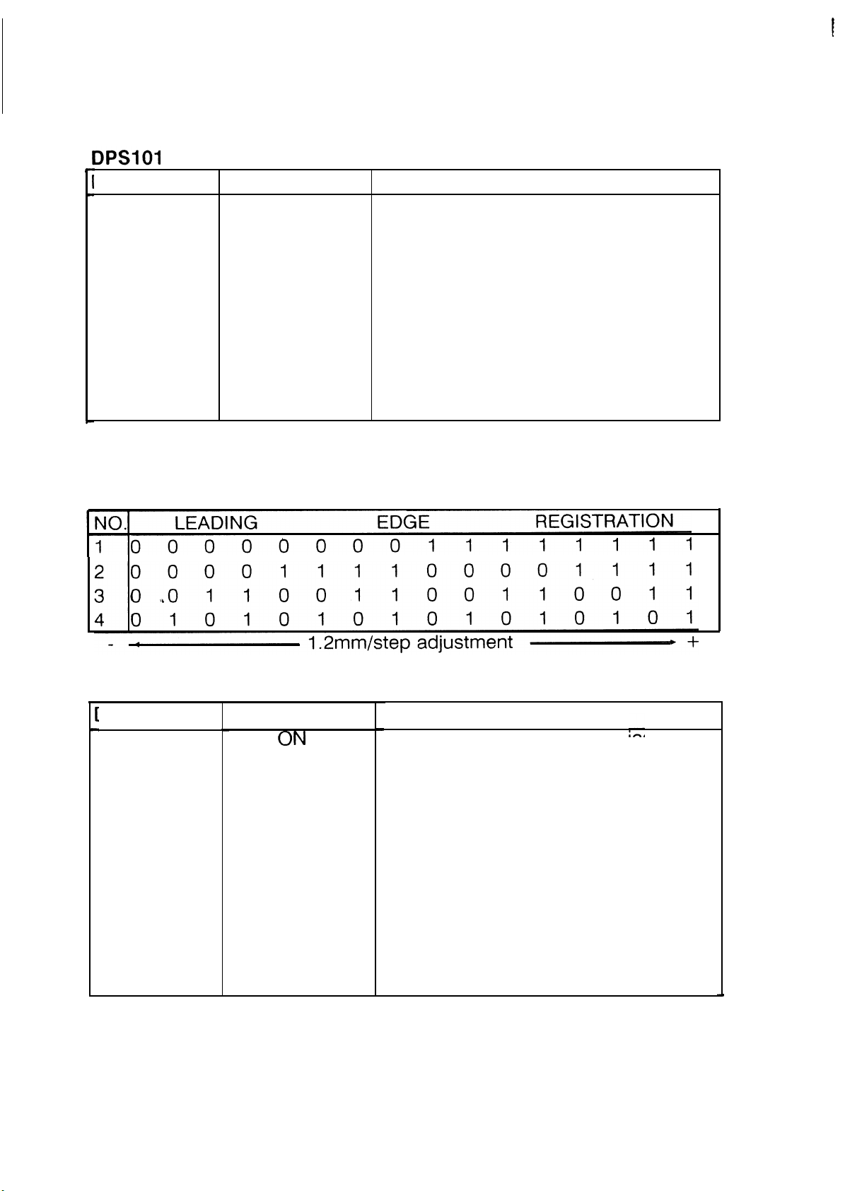
2-3 DIP Switches
I
1 Nov. ’87
DIP Switch
101-1
101-2
101-3
101-4 Lead edge registration adjustment 4
101-5
101-6
Normal
OFF
OFF
Lead edge registration adjustment 1
Lead edge registration adjustment 2
Lead edge registration adjustment 3
Test Mode
Free Run. (When in Free Run Mode,
Function
the paper feed solenoid, total
counter, and paper lift clutch do
not work. )
NOTE: The lead edge registration adjustment interval is 1.2 mm per step,
See the following table:
DPSI02
DIP Switch
102-1
102-2
102-3
102-4
Normal
OFF
OFF
OFF
Function
Selects ID sensor pattern bias level.
(See the following table.)
Selects ID sensor pattern bias level.
(See the following table.)
Selects the fusing temperature level.
(OFF = 185°C, ON = 175°C)
Warm-up idle. If ON the machine
idles for 8 minutes after warm-up.
(During warm-up idle, the cleaning
solenoid is energized and the development bias is fixed at 250 volts.)
2-5
Page 30

1 Nov. ’87
ID Sensor
DPSI02-I
OFF
ON
OFF
ON
Bias
DPS102-2 ID Bias
OFF
OFF
ON
ON
420 V
470 V
520 V
550 V
Page 31

1 Nov. ’87
3 TEST MODE
3-1 Output Mode:
This mode is used to make various adjustments and to check the operations
of electrical devices. Press the Start key to emergize the mode, and press
the C/S key to de-emergize.
Enterred No.
(Number keys)
1
2
3
4
5
6
7
8
9
10
11
14
15
16
Operation
Cleaning solenoid on
Fusing lamp on
#1
ID sensor LED on
Transfer corona on
Separation corona on
Exposure lamp on #2
Forward clutch on
Reverse clutch on #3
Paper lift clutch on
Paper feed solenoid on
Registration clutch on
Toner supply clutch on
Vacuum fan on
Exhaust blower on
17
18
20
21
22
23
24
25
26
27
28
29
70
88
99
Main motor on with the pulse counting
Main corona on
Bias Exp. 1 (100 V) on
#4
Bias Exp. 2 (150 V) on #4
Bias Exp. 3 (200 V) on #4
Bias Exp.
4 (250 V) on #4
Bias Exp. 5 (300 V) on #4
Bias Exp. 6 (350 V) on
#4
Bias Exp. 7 (500 V) on #4
Bias ID sensor low (470 V) on
Bias ID sensor high (520 V) on
Bias max. setting (620 V) on
Main motor on without the pulse counting
All indicators on #5
When DPS 101-6 (Free Run) is also on, to change
from “Test Mode” to “Free Run Mode”. #6
2-7
Page 32

conditions’. Be careful not to leave the lamp on for a long time.
#2
When the exposure lamp is turned on, after 20 seconds, auto-
shut off occurs.
the original ID sensor data (Hex code) is displayed in the opera-
tion panel (see 9-2 Original ID Sensor Adjustment).
#3 If the scanner is in the position
(H. P.) during this operation,
the clutch only turns on for a short time.
#4 When the bias amounts are measured, they may be
2-6% lower
than the stated amounts.
#5 After 20 seconds, auto-shut off occurs.
#6 If both the “Free Run” and “Test Mode” are turned on (“Test
Mode” has priority over “Free Run”), using this procedure will
change the copier to “Free Run”.
2-8
Page 33

3-2 Input mode:
1 Nov. ’87
This mode is used when checking the ON / OFF operation
switches. The data is displayed in the operation panel. Press
emergize the mode, and press the C/S key to de-emergize.
●
Enterred No.
Data 1
(Number keys) (Tens)
30
40
0
0
0
0
1
0
0
0
0
1
Data 2
(Units)
1
2
4
8
0
1
2
4
8
0
Function
Paper end sensor
Manual feed sensor
Paper exit sensor
Development set switch
Development set switch
Toner end sensor
Oil end sensor
Toner overflow sensor
DPS 101-5 (Test Mode)
Auxiliary
of sensors and
the Start key to
50
’
60
0
0
0
0
1
0
2
4
8
NOTE: a) Data information is displayed under the following conditions:
* For sensors when the phototransistor is receiving light from
✛
1
2
4
8
0
8
0
0
0
DPS 101-1 Regist. timing 1
DPS 101-2 Regist. timing 2
DPS 101-3 Regist. timing 3
DPS 101-4 Regist. timing 4
DPS 101-6 (Free Run)
Key counter set
Paper lift sensor
Scanner home position sensor
Registration sensor
the LED.
* For switches: when the switch is ON.
* For the key counter: when the key counter is set,
b) When more than two sensors or switches one actuated at the
same time, the datum is displayed in Hex code.
Example: Toner overflow sensor (4) + DPS 101-5 (8)
= C
(12).
Page 34

1 Nov. ’87
4. SERVICEMAN MODE
There are six serviceman modes, which have the following functions:
NAME
Toner End
Back Up
“C/S”, “0” and
●
"3"
Mode
ID Sensor “C/S”, “0” and
Pattern Copy
“6”.
Mode
Instant Ready
Mode
ID Sensor
Reading
Mode
Toner Feed
Mode
“DPS101-6
ON”, “C/S”, “O”
and
“7”.
“DPS101-6
ON”, “C/S”, “O”
and “8”.
“C/S”, “0” and
II II
●
9
Toner
Fill-up
Mode
“C/S”, “O” and
"I "I
●
FUNCTION
This is to confirm if the toner end
back up mode functions or not.*2
In this mode, a copy of the ID
pattern can be made.
The copier can be used without
the fusing warming up (factory
use).
In this mode, the Vsg / Vsp
readings are made every scan,
instead of every 10 scans.
Toner is fed into the development
unit until the keys are released.
The main motor continues to
turn, energizing the toner supply
clutch until the toner hopper is
full of toner (max. 10 seconds) *3
I
NOTE: *1
*2
*
To enter the “Serviceman Mode” correctly, the above mentioned
keys should be pressed whilst turning on the power.
After one copy, the “Toner End” turns on and continues to burn
for another five copies, at which time no more copies can be
made. (This is duplicating the “Toner End Mode”.)
This procedure is made when a machine is being installed, as
3
there is no toner in the hopper. The toner end sensor detects
whether or not toner is required, if so, toner is supplied for
max. of 10 seconds,
a
Page 35

1 Nov. ’87
5. SERVICE REMARKS
General Cautions
Keep hands away from mechanical drive components when the copier is
warming
the end of warm up. (The warm-up idle cycle occurs when DPS102-4 is ON.)
The copier also idles after warm up to lift the copy paper to the feed position
if paper is not in the correct feeding position.
Drum Charge
1. The corona wires should be cleaned at every service call with a dry cloth
or by sliding the corona unit in and out. Do not use emery paper or any
up. This is to avoid possible injury when the copier starts idling at
solvent for wire cleaning.
2. Do not touch the corona wires with your hands.
3. Make sure that the corona wires are correctly positioned between the “V”
slots and the cleaner pads,
4. After cleaning the charge corona unit, make sure
threads on the casing which may cause white lines on
Optics
1. Do not adjust the following parts:
a) Eccentric cams of the 2nd scanner and the lens
b) Fourth mirror angle adjusting screw.
that there are no
the copy.
bracket
2. Launa oil or an equivalent oil should be used to lubricate or clean the following:
a) Scanner guide rod (Cleaning)
b) Scanner guide rod pads (Lubrication)
c) Scanner guide plate (Lubrication/Cleaning).
Do not use any other kind of oil.
Page 36

1
Nov.
“87
3. Clean the exposure glass with water or glass cleaner.
4. Clean the mirrors with alcohol and/or water and a soft cloth only.
5. Do not touch the following parts with your bare hands:
Reflectors
a)
Exposure lamp
b)
Mirrors and lens
c)
6. After
adjusting the light intensity, check and adjust the original ID sensor.
Development
1. Be careful not to nick or scratch the development roller sleeve.
2. Place a sheet of paper under the development unit when it is out of the
copier.
3. Clean the drive gears after removing used developer.
4. Clean the development unit guide
5. When installing the development
pIate before re-installing the unit.
unit, keep it away from the drum sur-
face.
Toner Supply
1. The image density sensor and the pre-transfer lamp should be cleaned
at every EM or PM with a blower brush.
2. Do not touch the ID sensor pattern with bare hands.
3. Image density sensor adjustment is required when:
a) The image density sensor is replaced.
b) The main PCB is replaced.
c) The drum has been replaced and Vsg is out of specification.
d) There have been toner supply problems and Vsg is out of
specification.
2-12
Page 37

1 Nov. ’87
Transfer and Separation
1. The corona wires should be cleaned with a dry cloth at every EM or PM.
2. While the drum stay is removed and the drum is installed on the drum
guide, do not lift up the transport unit. (The corona casing will knock
against the drum and damage it.)
Cleaning
1
When servicing, be careful not to damage the edge of the cleaning blade.
8
●
Do not touch the cleaning brush with your bare hands.
2
●
Before pulling out the cleaning unit, place a sheet of
3
paper under it to
catch falling toner.
4
●
Be careful not to damage the drum with the pick-off pawls when pulling
out or inserting the cleaning
8
When a new cleaning blade and a new cleaning brush is installed, dust
5
them
with setting powder before re-installing the unit.
unit.
Fusing
1. After replacing the oil blade and oil supply pad, prime them with silicone
.
011
●
2. Be careful not to damage the edge of the hot roller strippers or their tension springs.
3. Do not touch the fusing lamp with your bare hands.
4. Be sure that the fusing lamp is not in contact with the inner surface of
the hot roller.
5. Be sure that the oil end sensor contacts the bottom of the oil tank.
2-13
Page 38

1 Nov. ’87
Handling the Drum
Never touch the drum surface with your bare hands.
Store the drum in a cool dry place away from heat.
When cleaning the drum, always use a pair of gloves. Do not throw
away cotton used for cleaning. Bring it back to the service depot for disposal according to local regulations.
Always prime the drum with setting powder after cleaning the drum, and
when installing a new drum.
●
To protect the drum, always apply setting powder to a new
5
cleaning
blade and new cleaning brush before installing them.
●
Before inserting or pulling out the drum, the cleaning unit
6
and the
development unit should be removed to avoid drum damage.
7
●
Send used drums to the distributor according to standard procedure.
Paper Feed
1. Grease the following parts with Mobil Temp. 78 periodically to avoid
noise and poor operation:
a) Slip clutch assembly
b) Paper feed clutch
2-14
Page 39

6. SPECIAL TOOLS AND LUBRICANTS
1 Nov. ’87
v
.
?
.
?-
Part Number
AO179505
52149500
52149501
54429101
54429106
54479104
54209504
54209505
54209507
54209508
54209550
54479078
54429103
Description
DG Gauge
Test Chart
Test Chart
OS-A4
OS-A4
Setting Powder
Drum Shoe
Shoe Adapter
Digital Thermometer
Digital Thermometer
Probe
Digital Multimeter
Deluxe Test Lead
Accessory Kit
Silicone Oil
Heat Resistant Grease
Mobil Temp. 78
Launa Oil
Remarks
2 pcs/sa
10 sheets/set
100 sheets/set
Beckman RMS 3030
Beckman DL
241
2-15
Page 40

●
SECTION 3
REPLACEMENT AND
ADJUSTMENT
Page 41

REPLACEMENT AND ADJUSTMENT
Page 42

.
Page 43

1. OPTICS
1-1 EXPOSURE GLASS REMOVAL
‘
●
Take off the left scale [A] (2 screws).
Slightly lift
NOTE:
a)
up the left edge and slide out the exposure glass
[B].
Place the exposure glass on a sheet of paper in order not to
scratch the surface.
When re-installing the exposure glass, make sure it is under the
b)
right glass holder [C], and flush with the tabs on the ID sensor
pattern plate[D].
When re-installing the left scale, make sure it is as close to the
,
c)
upper cover as possible (see illustration).
3-1
Page 44

1 Nov. ’87
1-2 SECOND MIRROR REMOVAL
”
Turn off the main switch.
1
.
.
2
Remove the exposure glass (see 1-1
Move the 1st scanner [A] 2/3 of the
.
3
Exposure Glass Removal).
Way to the right, by pushing it at the
rear.
.
4
Remove the rear spring pIate [B] by pressing the top and bottom of the
plate and moving the plate towards the back of the machine.
.
Carefully move the mirror
5
[C]
slightly towards the rear of the machine, in
order to release the front side.
●
Remove the front spring plate and lift out the 2nd mirror.
6
Clean the mirrors with a silicone cIoth or soft cloth and water, and then
7
●
●
dry
..
.
4
-.
&
●
c
[
3-2
Page 45

1-3 EXPOSURE LAMP REPLACEMENT
Do not touch the reflector or the new exposure lamp with your bare
hands. Use a strip of paper as finger oil. marks will become
discolored due to the heat.
1. Turn off the main switch.
2. Remove the exposure glass (see 1-1 Exposure Glass Removal).
3. Move the 1st scanner [A] so that the exposure lamp [B] is located in the
central area of the mylar [C].
4. For 115 volt machines, remove the front and rear exposure lamp terminal
covers [D] (1 screw each).
5. Remove the reflector cover [E] (2 screws),
6. Wrap a strip of paper [F] around the exposure lamp as shown.
7. Press the release lever [G] of the front lamp terminal and lift out the exposure lamp.
-
3-3
Page 46

1 NOV. ’87
8. Fit the lamp stopper [H] to the rear terminal of the new exposure lamp,
and install the lamp.
NOTE: Make sure the stopper fits in the terminal hole [1].
●
9
Reassemble the 1st scanner.
10
●
Check the exposure lamp position is correct (see 1-4 Exposure Lamp
Position Adjustment).
NOTE: A stopper is fixed to the exposure lamp in order to prevent possible
lamp rotation.
3-4
Page 47

1-4 EXPOSURE LAMP POSITION ADJUSTMENT
1 Nov. ’87
1. Turn off the main switch.
2. Remove the exposure glass (see 1-1 Exposure Glass Removal).
3. Move the 1st scanner so that the exposure lamp is located in the central
area of the mylar.
4. For 115 volt machines, remove the front and rear exposure lamp terminal
covers [A] (1 screw each).
- Horizontal Adjustment -
5. View the exposure lamp filament through the front and rear sight holes
[B]. The filament [C] should be directly beneath the sight holes.
6. To correct the position of the filament, turn the front and rear adjusting
screws [D].
3-5
Page 48

1 Nov. ’87
- Vertical Adjustment -
7. View the exposure lamp filament [A] through the right ventilation holes
[B] in the upper cover. The filament should be level with the sight holes.
8. To correct the position of the filament, turn the front and rear adjusting
knobs [C].
Page 49

1-5 SCANNER DRIVE WIRE REPLACEMENT
1 Nov. ’87
1. Turn off the main switch and unplug the copier.
2. Remove the platen cover, and upper cover (6 screws).
3. Remove the rear cover (2 screws).
4. Open the front cover and remove the following covers:
a)
lock plate cover (1 screw)
b) left cover
c)
right cover
(4
screws)
(4 screws).
NOTE: Open the exit cover when removing the left cover, and open the
manual feed table when removing the right cover.
5. Remove the main PCB [A] (4 screws, 19 connectors, 1
3 wire clamps), and the optics cooling fan assembly [B]
locking support
(3 screws, 3 2p
connectors, 1 wire clamp).
6. Loosen the wire clamp screw [C], unhook the tension
remove the scanner drive wire [E].
3-7
spring [D], and
Page 50

1 NOV. ’87
1
7. Hook the bead [A] of the new wire in the anchorage point on the rear
plate [B], and run it over the pulleys in the following order:
a) inner track of WP1
b) via the wire clamp [D] to WP2
c) inner to outer on WP3 (3 times) to WP4
d) outer track of WPI to WT.
8. Hook the tension spring [1] to its anchorage point [J].
NOTE: Rotate the
drive wire
scanner drive pulley in order to
moves smoothly and that it is
confirm that the scanner
not over-lapping at any
point.
Move the 1st and 2nd scanners to their furthermost right position (as
●
9
viewed from the rear
of the copier), and temporarily tighten the wire
clamp.
.
10
●
Perform the horizontal
nification Adjustment).
magnification adjustment (see 9-3 Horizontal Mag-
3-8
Page 51

1 Nov. ’87
I
1-6
REVERSE CLUTCH DAMPER REPLACEMENT
I
I
1. Turn’ off the main switch, unplug the copier, remove the rear cover (2
screws), upper cover (6 screws) and the right cover
2. Remove the main PCB
(4 screws, 19 connectors, 1 locking support, 3
(4 screws).
wire clamps).
3. Remove the reverse clutch damper cover [A] (1 “E” ring) and replace the
damper [B].
NOTE: a) Take care that the pin [C] does not fall out of position during the
above procedure.
b) For easier re-installation of the reverse clutch damper cover, posi-
tion the hole in the reverse drive gear [D] as shown in the illustration, and make sure the pin is horizontal. Then install the damper
cover making sure the long stud fits into the hole of the reverse
drive gear.
3-9
Page 52

1 Nov. '87
2. DEVELOPMENT
2-1 DEVELOPER REPLACEMENT
Take care not to damage the upper brush seal.
After removing used developer, clean the drive gears.
Open the front cover, loosen the development retainer plate (1 screw),
raise the development lock lever and pull out the development unit.
Separate the toner tank [A] from the development unit [B] (2 screws).
Remove the development brush cover [C] (2 screws) and clean it.
Set the development unit on a large sheet
of paper with the inlet facing
downwards.
Empty the development unit by turning
the paddle roller knob [D]
counterclockwise.
4
.
3-10
Page 53

‘.
1 Nov. ’87
I
●
6
To remove the trapped developer
hold up the unit at an angle, and
at the ends of the development unit,
alternatively turn the knob and gently
shake the unit.
7
●
Repeat steps 5. and 6. until all the developer is removed.
.
8
Place the development unit on a level surface and pour in one pack of
FT3300 developer [E] (750 g) while turning the paddle roller knob [F].
●
9
Put the used developer into a disposal bag, and dispose of it according
to local regulations.
3-11
Page 54

1 NOV. ’87
2-2 DEVELOPMENT SET SENSOR REPLACEMENT
1. Turn off the main switch and unplug the copier.
2. Remove the development unit (see 2-1 Developer
Replacement).
3. Remove the main PCB (see 1-6 Reverse Clutch Damper Replacement), --
4. Remove the 1 screw, 2 locking supports, and CNI on the CTB power
pack [A],
and swing it to the
right.
5. Remove the paper feed clutch bracket [B] (2 screws, 1 wire clamp).
6. Remove the development set sensor [C] and bracket [D] (2 screws, 1
connector, 1 wire clamp).
7. Separate the sensor from the bracket and replace it.
3-12
Page 55

2-3 TONER SUPPLY CLUTCH REPLACEMENT
1 NOV. ’87
1. Remove the main PCB (see 1-6 Reverse Clutch Damper Replacement).
2. Remove the toner supply clutch assembly [A] (3 screws), and separate
the clutch [B] from the bracket by removing the clutch-shaft [C] (1 “E”
ring).
3. Replace the clutch.
NOTE: Make sure the groove of the toner supply clutch is correctly
engaged with the bracket.
Page 56

1 Nov. ’87
2-4 IMAGE DENSITY SENSOR CHECK AND ADJUSTMENT
NOTE:
The ID sensor adjustment is required in the following situations:
a) When the Main PCB is replaced.
b) When the drum has been replaced and Vsg is out at standard.
c) When a problem with toner supply occurs, and checking the ID
sensor voltage shows the Vsg is out of standard.
ADJUSTMENT STANDARD: 4.0 ±0.2 (CC ± 10)
METHOD A: Reading from the CPU
1. Clean the following parts:
a) image density sensor
b) optics
c) charge corona wire
d) quenching lamp.
2. Place 2 or 3 sheets of white paper
lower the platen cover.
(A4 or LT) on the exposure glass and
3-14
Page 57

3. Turn off the main switch and turn on DPS 101-6 (Free Run) on the main
PCB.
4. Turn on the main switch while pressing the “C/S”, “O”, and “8” keys at
the same time.
5. When the copier is ready, press the “Start” key in order to show the Vsg
voltage in the operation panel.
NOTE: a)
b)
Vsg and Vsp amounts are shown alternatively each second.
The amounts are shown in Hex code.
6. If Vsg
3-15
Page 58

1 Nov. ’87
METHOD B: Reading from a Digital Multimeter
1. Clean the image density sensor.
2. Turn off the main switch and turn on DPS 101-5 (Test Mode) on
main PCB.
I
the
J
1
1
I
1
3. Hook up the digital multimeter leads as follows:
a) positive lead to TP104
b) negative lead to TP103 (GND).
4. Turn on the main switch.
5. Press the “3” key, and then the “Start” key.
6. Confirm the reading on the digital multimeter.
3-16
Page 59

1 Nov. ’87
7. If Vsg is incorrect, adjust VR102 on the main PCB in order to obtain 4 ±
0.2
volts.
8. Press the “C/S” key to stop the copier, turn off the main switch and turn
off DPS 101-5.
3-17
Page 60

1 Nov. 987
2-5 DOCTOR GAP ADJUSTMENT
ADJUSTMENT STANDARD: 0.72 mm (0.028”)
NOTE: This adjustment is done only when the doctor blade has been
removed or replaced.
1. Remove the upper brush seal cover [A] (2 screws).
2. With the development roller facing upwards, turn the roller sleeve in the
opposite direction to normal operation by using the development roller
gear [B], until the roller is free from developer.
3. Loosen the doctor plate [C] (4 screws) and clean the development roller
●
[D]
4. Insert the Doctor Gap Gauges [E] (P/N A01 79505) near both ends of the
development roller between the doctor blade.
NOTE: Make sure the development roller, doctor blade gauges and doctor
blade plate are free from developer.
5. Press the doctor blade plate and tighten the screws.
6. Pull out the doctor blade gauges.
Do not scratch the development sleeve with the
3-18
gauges.
Page 61

1 Nov. ’87
2-6 IMAGE DENSITY SENSOR AND DRUM Thermistor
REPLACEMENT
1. Turn off the main switch and unplug the copier.
2. Remove the rear cover (2 screws).
3. Disconnect CNI 08 (3p) on the main PCB, and CN2 (2p) on the power
pack.
4. Open the front cover, lower the T/S corona unit and remove the following
parts:
a) development unit
b) charge corona unit
c) drum stay
d) cleaning unit
e) drum flange
f) drum.
g) drum guide.
5. Remove the image density sensor and drum thermistor assembly [A] (1
screw), by pulling towards the front of the machine.
NOTE: Take care not to drop the screw during removal and re-installation.
3-19
Page 62

1 Nov. ’87
6. Replace the sensor assembly.
NOTE: a)
b)
When installing the assembly, first feed the two harnesses
through the hole [B] and towards the rear of the machine.
Then
with the sensor facing downwards [C], insert the assembly
in the hole and rotate to the left (1 and 2).
Install the assembly, making sure the 2 hooks and positioning pin
are correctly fixed.
Take care not to move the drum thermistor out of position by
releasing the thermistor clamp plate during removal and re-instalIation.
3-20
Page 63

3. CLEANING
3-1 USED TONER DISPOSAL
1 Nov. ’87
Remove the cleaning unit, place it on a sheet of paper and turn the cleaning brush in the cleaning direction, in order to feed the remaining toner
in the cleaning unit into the used toner tank.
2
●
Remove the used toner tank upper cover [A] (5 screws).
8
3
Empty the used toner into the used toner bag.
NOTE: Dispose of the used toner according to local regulations.
4. Clean the gears and the exterior of the cleaning unit, then re-install the
used toner tank upper cover, taking care not to damage the entrance
mylar.
3-21
Page 64

1 NOV. ’87
3-2 CLEANING BLADE REPLACEMENT
I
1. Remove the cleaning unit [A], and remove the cleaning blade [B] (1
shoulder screw).
2. Replace the cleaning blade being careful not to touch the edge of the
blade.
After installing the blade, make sure it swivels from side to side.
3-22
Page 65

3-3 CLEANING BRUSH REPLACEMENT
1 Nov. ’87
v
1. Remove the cleaning unit and remove the cleaning brush gear [A] (1 “E”
ring).
2. Remove the cleaning brush idle gear [B] (1 screw), and the front and
rear bushings [C] from the cleaning brush shaft (1 “E” ring each).
3. Remove the cleaning brush shaft holder [D] (1 screw), and remove the
cleaning brush
[E].
NOTE: When removing the cleaning brush, first remove the front end of the
brush and then pull it out, taking care not to damage the mylar.
4. Holding the new cleaning brush by the shaft only, first fit the rear end of
the brush in the shaft holder and then the front end.
NOTE: When re-installing the cleaning brush gear, make
edge of the gear is facing the rear of the machine.
3-23
sure the rounded-
Page 66

1 Nov. ’87
3-4 PICK-OFF PAWL REPLACEMENT
1. Remove the cleaning unit and remove the 2 pick-off pawls [A] (1 snap
ring each).
2. Replace the
pick-off pawls, making sure the pick-off bars [B] are fitted
correctly in between the pick-off pawls’ tails.
NOTE: When replacing the pick-off pawls, it is advisable to replace both of
the pawls at the same time.
3-24
Page 67

3-5 CLEANING PRESSURE ADJUSTMENT
ADJUSTMENT STANDARD :44 mm
Take care when doing this procedure as the power is on.
NOTE: When doing this procedure, make sure that the cleaning unit and
the drum are fitted in the machine.
1. Turn off the main switch.
2. Remove the rear cover and turn on DPS 101-5 [A] on the main PCB.
3. Turn on the main switch, enter “1” in the 10 keys, and then press the
“Start” key [B] (cleaning solenoid on).
4. Loosen the 2 cleaning solenoid fixing screws [C], and move the assemb-
ly [D] until the distance between the two points (see illustration) is 44
mm.
5. Tighten the fixing screws and then press the “C/S” keY to stoP the coPier”
6. Turn off the main switch and turn off DPS 101-5.
3-25
Page 68

4.
QUENCHING
4-1 PRE-TRANSFER LAMP REPLACEMENT
1. Turn off the main switch and unplug the copier.
2. Remove the following parts:
a) development unit
b) charge corona unit
c) drum stay
d) cleaning unit
e) drum flange
f) drum
g) main PCB.
3. Remove the paper feed solenoid assembly [A] (2 screws), and loosen
the main motor assembly [B] (4 screws) and the pulse generator bracket
[C] (1 screw).
4. Remove the registration clutch stopper bracket [D] (1 screw), and the
registration clutch [E] (1 “E” ring).
3-26
Page 69

1 NOV. ’87
NOTE:
To ease the fitting or removing of the clutch, move the main motor
assembly towards the right.
5. Remove the PTL [F] (1 screw, 1 connector) by pulling it out diagonally,
thus not hitting the main motor.
6. Replace the PTL.
NOTE: a)
When re-installing the PTL, confirm the positioning pin is correctly
inserted.
b)
Make sure the groove of the registration clutch is correctly
engaged with the stopper bracket.
I
3-27
Page 70

1 NOV. ’87
4-2 QUENCHING LAMP
REPLACEMENT
1. Turn off the main switch and unplug the copier.
2. Remove the following parts:
a)
development unit
b) charge corona unit
c) drum stay
d) cleaning unit
e) drum flange
f) drum.
3. Remove the left locking support [A] on the ac PCB [C]
4. Remove the quenching lamp [B] (1 screw, 1 connector, 1 wire clamp)
while swinging the ac PCB to the right.
5. Replace the quenching lamp.
NOTE: When re-installing the quenching lamp, confirm the positioning pin is
correctly inserted.
3-28
Page 71

5. PAPER FEED
1 Nov. ’87
5-1
PICK-UP AND FEED ROLLER REPLACEMENT
1
●
Open the manual feed table [A], and remove the front and rear manual
feed links [B] (1 “E” ring each).
2 ●
Remove the manual feed table (1 “E” ring, 1 stud screw).
●
Remove the right plate holder [D] (1 screw), and remove the manual
3
feed pIate [E].
4
●
Gently push down the pick up bracket [F] and remove the pick up roller
[G] (1 snap ring).
.
Remove the feed roller (1 snap ring).
5
●
Replace both rollers.
6
NOTE: a)
When replacing the feed roller, make sure that the open end of
the roller faces the rear of the machine.
b)
When re-installing the manual feed plate, make sure the cut out
area is facing the inside of the copier as shown.
3-29
Page 72

1 Nov. ’87
5-2 REVERSE ROLLER REPLACEMENT
1
●
Remove the reverse roller cover [A] (2 screws), the reverse roller [B] (1
snap ring), and the slip clutch assembly.
.
Disassemble the slip clutch assembly, clean and lubricate the spring with
2
Mobil Temp 78.
.
Reassemble the clutch assembly, making sure that the pin fits correctly
3
into the cut-out part of the assembly.
Replace the reverse roller.
4
●
3“30
Page 73

.-4
1. Turn off the main switch and unplug the copier.
2. Remove the rear cover (2 screws) and the right cover (4 screws).
3. Remove the CTB power pack [A] (1 screw, 2 locking supports, 2 connec-
tors, 3 terminals).
4. Remove the paper feed clutch bracket [B] (2 screws, 1 wire clamp).
In order not to damage the main PCB, pull out the lower part of the
bracket first.
5. Remove the pick-up arm [C] (1 “E” ring), paper feed solenoid assembly
[D] (2 screws, 1 connector), and the feed clutch cam [E] (1 “E” ring).
3-31
Page 74

1 Nov. ’87
6. Remove the paper feed clutch [F] (1 “E” ring), and disassemble the
clutch (see illustration).
7. Clean and lubricate the clutch spring with Mobil Temp. 78, then
assemble the clutch, making sure that the spring [H] is fitted correctly
(see illustration). Then fit the washer and the ratchet.
8. Reassemble all parts.
NOTE: a) Open the ratchet pawl [1] when re-installing the cam on the shaft.
b) Make sure the rod of the pick-up arm [C] is correctly positioned
in between the pick-up lever
[J] (see illustration).
3-32
Page 75

5-4 PAPER LIFT CLUTCH
REPLACEMENT
I
Turn off the main switch and unplug the copier.
Remove the rear cover (2 screws), and the right cover (4 screws).
Remove the power pack (1 screw, 2 locking supports, 2 connectors, 3
terminals), and remove the sector gear (1 screw) [A].
Remove the paper feed clutch bracket (2 screws, 1 wire clamp).
In order not to damage the main PCB, pull out the lower part of the
bracket first.
5. Remove the pick-up roller arm (1 “E” ring), paper feed solenoid assembly
(2 screws, 1 connector), and the feed clutch cam (1 “E” ring).
6. Remove the paper lift gear [B] (1 “E” ring), and the paper lift clutch assembly [C] (2 “E” rings, 1 connector, 1 spring).
NOTE: a) For easy removal, pull the assembly and push the drive shaft [D]
at the same time. Do not manually rotate the drive shaft [D]. This
action may deform the clutch spring.
3-33
Page 76

1 Nov. ’87
b) Take care not to drop the idle gear [E] when removing the as-
sembly.
7. Fit the lift release spring [F] to the new paper feed clutch assembly and
install the assembly.
NOTE: a)
b)
c)
When installing the assembly, make sure that the lift clutch shaft
is in the correct position (see illustration) and take note that it
has a “D” cut when installing the clutch.
When re-installing the paper lift drive gear, make sure the
non-
toothed part of the gear faces inwards.
In case the lift pressure spring becomes loose, the following pro-
cedure should be followed:
(1)
(2)
remove the manual
remove the rear cassette guide (2 screws, 1 positioning
feed table
tab)
(3)
(4)
re-install the shaft spring
when re-installing the rear cassette guide, slightly pull the
shaft towards the rear at the same time.
3“34
Page 77

1 Nov. ’87
5-5 REGISTRATION SENSOR
REPLACEMENT
1
9
Turn off the main switch.
2
9
Open the front cover and remove the development unit.
●
Remove the right inner cover [A] (4 screws).
3
4
.
Uncouple the registration sensor connector [B] and snap-out the male
connector [C] from the front plate (see illustration).
.
Lower the transport unit and remove the T/S corona unit.
5
9
6
Remove the front holding pin [D] (1 screw), and remove the registration
guide [E] taking care that the guide does not full.
7
.
Remove the registration sensor [F] and bracket [G] (1 screw, 1 connec-
tor) from the registration guide [E].
●
8
Separate the sensor from the bracket and replace it.
NOTE: When re-installing, make sure the
correctly fitted over the rear holding
3-35
rear of the registration guide is
pin.
Page 78

1 Nov. ’87
5-6 PAPER END AND PAPER LIFT SENSOR REPLACEMENT
1. Turn off the main switch.
2. Open the manual
feed table and slide the paper guides [A] to their
widest position.
3. Remove the upper
entrance guide [B] (2 screws).
- Paper End Sensor -
4. Remove the paper
end sensor assembly [C] (1 screw, 1 connector).
5. Separate the sensor [D] from the bracket, and replace the sensor.
- Paper Lift Sensor -
4. Remove the paper lift sensor assembly [E] (1 screw, 1 connector)
5. Separate the sensor [F] from the bracket, and replace the sensor.
3-36
Page 79

1 Nov. ’87
5-7 MANUAL FEED SENSOR
REPLACEMENT
1. Turn off the main switch.
2. Remove the front and rear manual feed links [A] (1 “E” ring each), and
then remove the manual feed table [B] (1 “E” ring, 1 stud screw).
3.
Remove the upper entrance guide [C] (2 screws).
4. Remove the right plate holder [D] (1 screw).
5. Remove the manual feed sensor [E] with the bracket [F] (1 screw, 1 connector).
6. Separate the sensor [E] from the bracket and replace the sensor.
3“37
Page 80

1 Nov. ’87
6. TRANSPORT AND FUSING
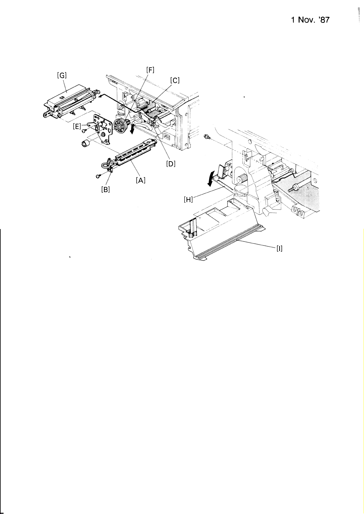
6-1
TRANSPORT BELT REPLACEMENT
1. Open the front cover and remove the following parts:.
a) development unit
b) main charger corona
c) drum stay
d) cleaning unit
e) drum flange
f) drum
g) drum guide
h) transfer corona unit.
I
2. Remove the left inner cover (3 screws), open the exit cover and remove
the fusing cover (2 screws).
3. Unfix the front [A] and rear [B] stoppers (1 screw each) and take out the
transport unit [C] whilst holding up the registration guide [D].
4. Remove the front and rear pressure springs [E] (1 each), and remove
the front registration roller bushing [F] (1 “E” ring).
3-38
Page 81

●
Remove the front transport gear [G] (1 “E” ring), and the front transport
5
bracket
.
6
Take off the front transport drive shaft bushing [J], and remove the rear
[1]
(4 screws).
transport gear [K] (1 “E” ring).
7
✎
Separate the transport belt assembly from the rear transport bracket [L]
(2 screws), and take off the rear transport drive shaft bushing [M].
●
8
Turn over the transport belt assembly [H], and remove the lower
transport cover [N] (2 screws).
.
9
Move the transport drive shaft [0] out of position, releasing the transport
belt tension.
10. Replace all 3 transport belts [P].
NOTE: a)
It is advisable to replace all 3 belts at the same time, making
sure that the ribbed side of the belt is facing outwards.
b)
When re-installing the transport belt assembly, make
sure that the
transport grounding plate [Q] is in its correct position.
When re-installing the rear transport gear, make sure it is facing
c)
the rear of the copier.
After assembling the
d)
unit, turn the drive shaft to correctly position
the transport belts.
3“39
Page 82

1 Nov. ’87
6-2 OIL SUPPLY PAD REPLACEMENT
1. Open the front cover and remove the following
parts:
a) development unit
b) main charger corona unit
c) drum stay
d) cleaning unit
e) drum flange
f) drum
g) drum guide.
2.
Open the exit cover [A] and remove the fusing cover [B] (2 screws).
3.
Lift out the oil supply pad [C] and replace it.
NOTE: a)
Before fitting the new pad, it
should be primed with silicone oil
[D]
The notches of the oil supply
b)
pad should rest on the 2 hooks Of
the oil blade bracket.
Make sure that the oil
c)
SuppIy pad tail is placed in the oil sump.
3-40
Page 83

6-3 OIL BLADE
REPLACEMENT
1. Remove the oil supply pad (see 6-2 Oil Supply Pad Replacement).
2. Turn and lift out the oil blade assembly [A].
3. Separate the blade from the bracket (3 screws) and replace the oil blade.
NOTE: Before fitting the oil blade assembly, prime the edge of the blade
with silicone oil.
3-41
Page 84

1 NOV. ’87
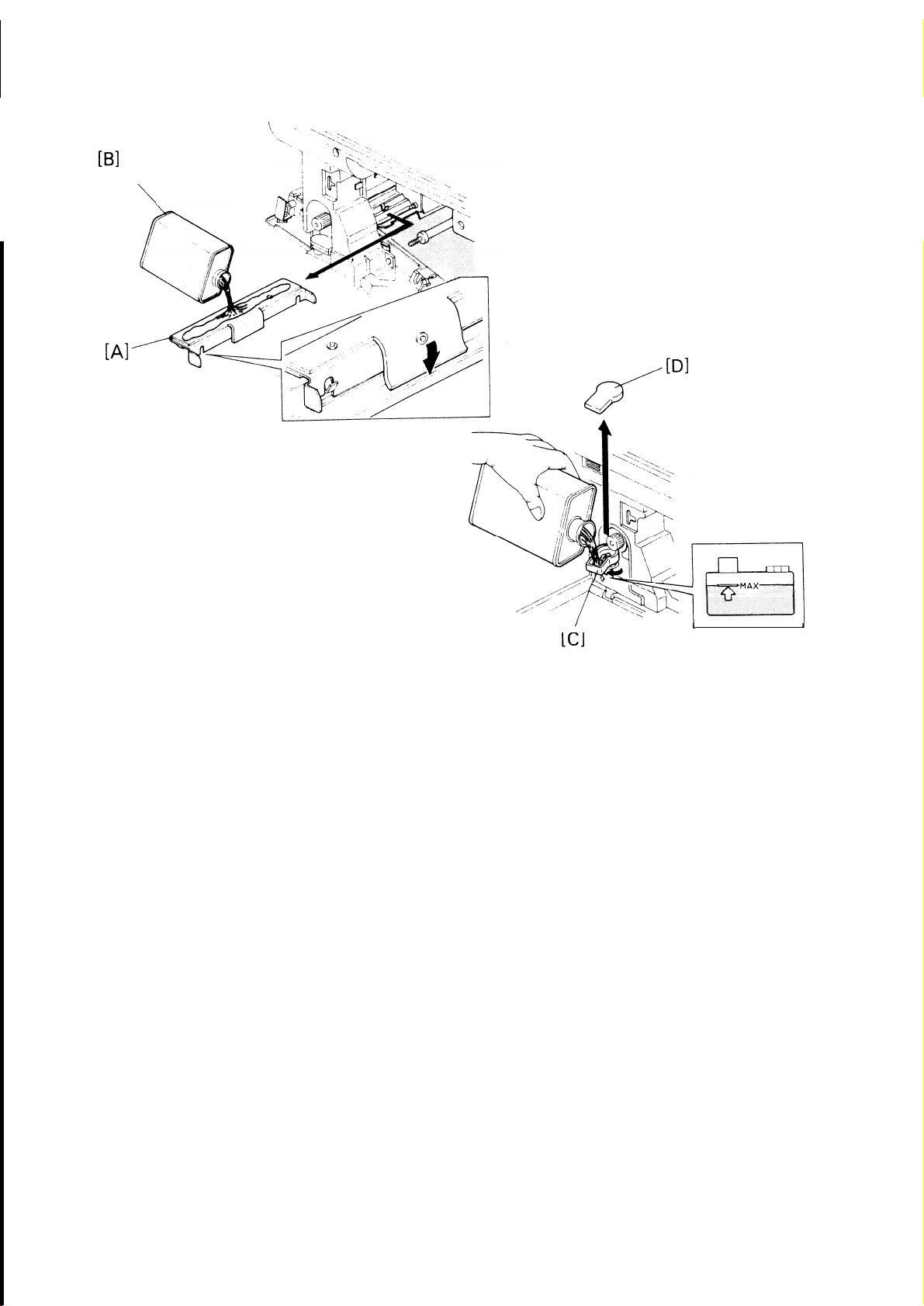
6-4 FUSING THERMISTOR REPLACEMENT
1. Remove the oil blade assembly (see 6-3 Oil Blade Replacement).
2. Pull off the fusing knob, turn the silicone oil tank mouth to the front and
remove the left inner cover (3
screws).
3. Remove the silicone oil tank assembly (2 screws, 1 connector, 1 wire
clamp), and remove the oil sump.
4. Remove the upper fusing entrance guide [A] (1 screw, 1 connector, 1
wire clamp), and unhook the thermistor spring [B].
5. Replace the fusing thermistor [C].
NOTE: a) When installing the thermistor, make
sure the harness is correct-
ly wound around the upper fusing entrance guide.
b) During re-installation, make
sure that the holes of the guide and
the tab of the oil sump are in their correct position, and that the
oil end sensor holder is correctly positioned in the
3-42
sensor groove.
Page 85

6-5 THERMOSWITCH REPLACEMENT
I
1 Nov. ’87
1
.
Turn off the main switch and unplug the copier.
2
●
Remove the fusing cover (see 6-2 Oil Supply Pad Replacement), and the
left inner cover (3 screws).
Disconnect the thermoswitch terminal [A] from the lamp control PCB [B]
and release the harness from the 2 wire clamps.
4
.
Remove the rear cover and left covers, and un-couple the rear fusing
lamp connector [C] and release the harness from the wire clamp.
●
Place a sheet of paper [D] over the top of the hot roller.
5
.
Remove the stripper pawl setting plate [E] (2 screws), taking care that it
6
does not drop and damage the fusing rollers.
Remove the thermoswitch [F] (1 screw), taking care not to damage the
hot roller.
●
Replace the fusing thermoswitch,
8
making sure that the harness is
correctly run over the exhaust blower bracket.
NOTE: Take care not to bend the thermoswitch during this procedure.
3=43
Page 86

1 Nov. ’87
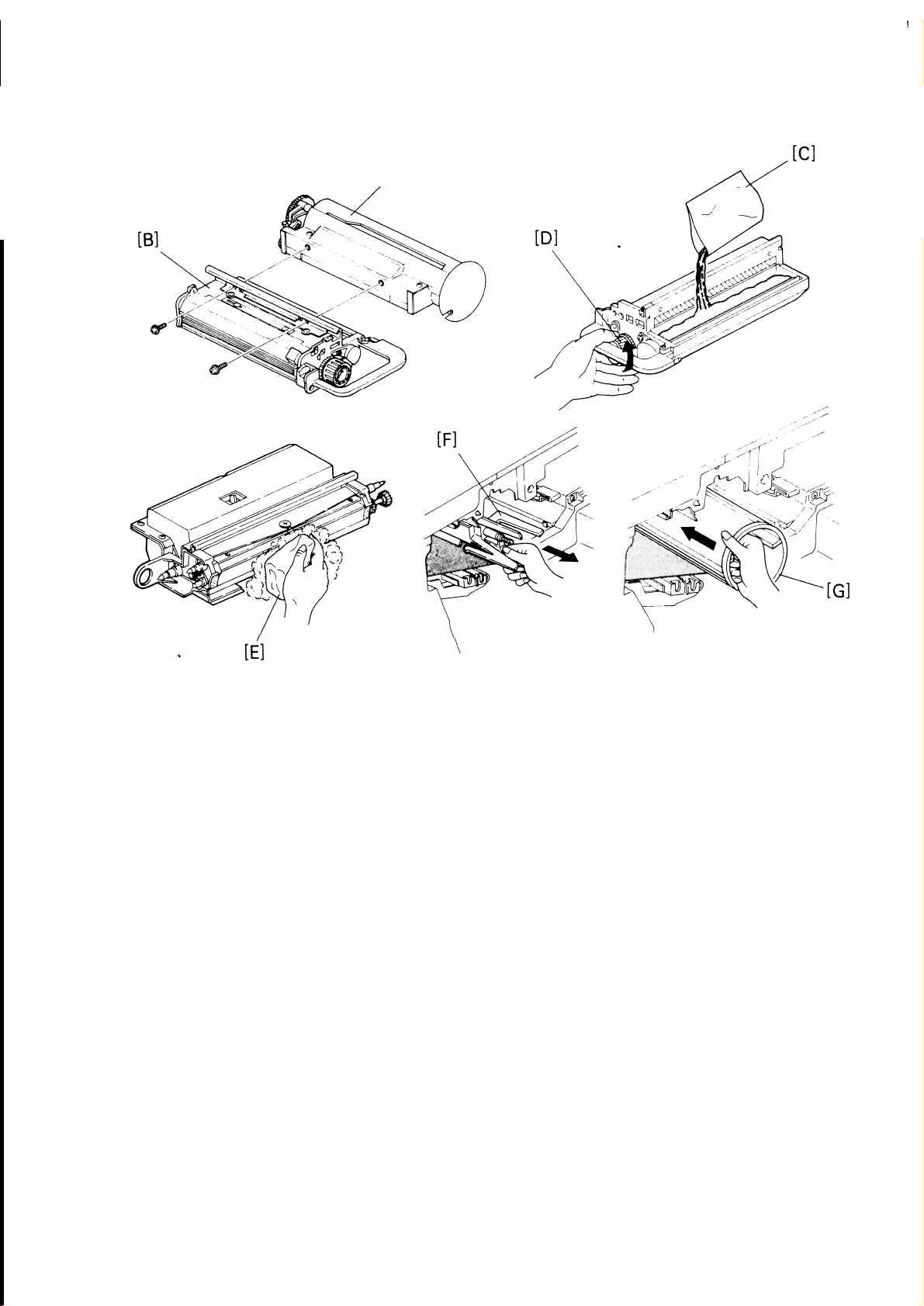
6-6 HOT ROLLER
REPLACEMENT
1
●
Turn off the main switch and unplug the copier.
●
2
Remove the fusing thermistor assembly (see 6-4 Fusing Thermistor
Replacement), and the rear cover (2 screws).
.
Un-couple the rear fusing lamp connector [A] and remove the holder [B]
3
(1 screw).
4
●
Disconnect the fusing lamp terminal [C] from the lamp control PCB [D]
and release the harness from the wire clamp.
.
Remove the front fusing lamp holder [E] (1 screw), and pull out the
5
fusing lamp [F].
Do not touch the surface of the fusing lamp with your bare hands.
Hold the lamp terminals at all times.
6. Place a screw in the front and rear un-tapped holes [G] (see illustration),
and remove the pressure springs [H].
NOTE: This is to hold the pressure roller when releasing the pressure
springs, as the roller drops and could be damaged.
3-44
Page 87

7
.
●
Place a sheet of paper in between the hot and pressure rollers.
●
Remove the front hot roller gear [1] and bearing [J] (1 “C” ring).
8
●
Remove the rear hot roller gear [K] (1 “C” ring), taking care that the bear-
9
ing does not drop down and damage the pressure roller.
10
.
Slide out the hot roller [L] from the front side, taking care not to damage
the fusing thermoswitch.
.
Tear off the ends of the protective paper [M] from the new hot roller and
11
install it.
NOTE: This is to make sure that the fusing thermoswitch is not damaged
by the protective paper.
12
●
After installation of the hot roller, bearing, and gears, remove the sheet
of paper in between the hot and pressure rollers, and then remove the
protective paper.
13
●
Re-install the pressure springs, making sure not to forget to remove the
2 screws from the un-tapped holes holding the pressure roller.
3“45
Page 88

1 Nov. ’87
6-7
PRESSURE
ROLLER REPLACEMENT
1. Turn off ;he main switch and unplug the copier.
2. Remove the following covers:
a) left inner cover (3 screws)
b) rear cover
c) lock plate cover (1 screw)
d) left cover
3. Remove the 2 screws of the oil bracket and swing the silicone oil tank
[A] to the right.
4.
Remove the 2 pressure springs [B] and take out the pressure roller
(2 screws)
(4
screws).
[C],
3-46
Page 89

1
Nov.
'78
I
✎
Remove the 2 bushings [D] (1 “E” ring each), and fit them on the new
5
pressure roller [E] .
.
6
Install the new pressure roller and set it in the pressure release position
by lifting the pressure levers [F] and placing two screws [G] in the un-
tapped holes (see illustration).
Remove the protective paper [H], fit the pressure springs and remove
7
.
the 2 screws from the untapped holes.
✎
Assemble the copier.
8
NOTE:
During re-assemblyj make sure the oil end sensor holder is correctly
positioned in the sensor grove.
3-47
Page 90

1 Nov. ’87
6-8 HOT ROLLER STRIPPER REPLACEMENT
1. Open the exit cover and unhook the hot roller stripper springs [A] and
remove the strippers [B].
2. Replace the strippers and fit the springs.
NOTE: It
is advisable to replace the strippers as a
set.
3-48
Page 91

6-9 FUSING PRESSURE ADJUSTMENT
1. Open the exit cover.
2. Move the pressure springs [A] to the desired position as in the table
below:
Setting
1
2
3
Fusing Pressure
12.48 kg
16.88 kg
18.28 kg.
NOTE: Make sure the front and rear pressure springs are in the same posi-
tion.
3-49
Page 92

1 Nov. ’87
6-10 PAPER EXIT SENSOR REPLACEMENT
1
● Turn off the main switch and unplug the copier.
Remove the following covers:
a) rear cover
(2 screws)
b) lock plate cover (1 screw)
c) left cover
Remove the connector-stopper
(4 screws).
bracket [A] (2 screws) and disconnect
the exit sensor connector [B].
Remove the exit assembly [C] (1 “E” ring) by pushing the right exit bracket arm [D] inwards.
Remove the lower exit guide [E] (1 screw, 1 shoulder screw).
Remove the exit sensor
bracket [F] (2 screws, 2 shoulder screws).
Replace the exit sensor
Reassemble all parts.
NOTE:
When re-installing the exit sensor bracket, make sure the positioning
pins on the exit bracket are correctly fixed.
[G] (1 screw,
3“50
2
wire clamps).
Page 93

7. CORONA
1 Nov. ‘87
7-1
CORONA WIRE REPLACEMENT
Do not handle new corona wires with your bare hands. Oil on the wire
will cause uneven charge on the drum.
Do not rub the corona wires with rough material (sandpaper, etc.)
because the corona wires are carbon-coated.
Do not use any solvent to clean the wire as it will cause uneven
charge on the drum.
When removing the endblock covers, be careful not to break off the
side hooks.
I. Charge Corona Wire.
1.
Slide the wire cleaner
2. Remove the front [C]
3. Slide the wire cleaner back to the front end block and remove it (by rotating it backwards and then lifting it upwards).
[A] away from the end block [B],
and rear [D]
end block covers.
3-51
Page 94

1 Nov. ’87
4
.
Remove the corona wire [E] from the front end block first.
●
Hook the tension spring [F] on to the new wire and install making sure
5
that the wire is correctly positioned in the “V” slot [G].
Reassemble the wire cleaner, and then the end block covers.
●
6
1
T/S Corona Wires.
.
11
.
1
Remove the corona paper guide [H] by pressing the stopper and pulling
it towards
Remove
2
.
●
Remove the corona wires [J] by pulling the front end blocks [K] towards
3
the
the
rear.
rear
end block cover [1].
4
the front and lifting upwards. (See illustration.)
4
.
Replace the corona wires, making sure they are correctly positioned in
the “V” slots [L].
NOTE: Take care not to damage the transfer entrance mylar during this pro-
cedure.
3-52
Page 95

I
7-2 DRUM CURRENT
ADJUSTMENT
NOTE: a) The drum currents vary with environmental conditions such as
humidity and atmospheric pressure. Generally it is not necessary
to adjust the drum currents because they have already been ad-
justed for a range of environments at the factory.
b)c)Drum current adjustment may be required when there are
problems with paper separation, incomplete toner transfer,
and/or image density.
Make sure that the main switch is turned off when you change
the range on the digital multimeter. If it is not, the multimeter may
be damaged.
I
Preparation
I
●
1. Turn off the main switch and remove the following parts:
development unit
a)
charge corona unit
b)
drum stay
c)
cleaning unit
d)
drum flange
e)
f)
drum
drum guide
9)
T/S corona unit.
h)
2. Clean
or replace each corona wire, and clean the corona units and the
cleaning unit.
3. Actuate the door switch.
4. Remove the rear cover (2 screws).
5. Turn on DPS 101-5 (Test Mode) on the main PCB.
NOTE: The fusing unit does not warm up when in Test Mode.
3-53
Page 96

1 NOV. ’87
Install the
●
6
drum shoe and adapter on
rear.
7
●
Route the
●
8
Connect the drum shoe and the digital
shoe lead wires out through
a) Positive lead to the red lead clip.
b) Negative lead and the black lead clip to the machine ground.
the drum shaft with the lip to the
the development unit opening.
multimeter leads as shown:
Page 97

IL Charge Corona
1 Nov. ’87
Disconnect CN2 (2p) on the CTB power pack.
Slide the drum shoe [A] to its rear limit as shown (X).
Position the drum shoe so that the axis of shoe is aligned with the
charge corona wire [B] as shown.
4
●
Re-install the drum stay [C] (1 screw, 1 knob) and the charge corona
unit [D].
●
5
Turn on the main switch, press the 10 key “18“, and press the “Start” key.
Note the reading, and then press the “C/S” key.
Move the drum shoe to the front as shown (Y)
and repeat steps 4 to 7.
j
3-55
Page 98

1 Nov. ’87
9. Adjust the front
ings differ. The
than 0.2
WA.
corona wire height
difference between
adjusting screw [F] if the two read-
front and rear should not be more
NOTE: After adjusting the front side, confirm the rear reading once again.
Position the drum shoe on the center of the shaft (Z).
10
●
11
9
Press the 10 key “18“, press the “Start” key, and adjust the charge
corona current by turning “VRC” on the CTB power pack [G].
12
●
Press the “C/S” key, turn off the main switch, and turn off the DPS101 -5.
3-56
Page 99

Ill. Transfer Corona
1. Re-install the T/S corona unit and position the drum shoe [A] on the cen-
ter of the shaft, so that the axis of the shoe is aligned with the transfer
corona wire [B] as shown.
2. Re-install the drum stay [C] (1 screw, 1 knob).
[D]
4. Turn on DPS101 -5 (Test Mode) on the main PCB.
5. Turn on the main switch and press 10 key
“4”, and press the “Start” key.
Note the reading.
69 Adjust the transfer corona current by turning
“VRT” on the CTB power
pack [E].
7. Press the “C/S” key, turn off the main switch, and turn off DPS101-5.
3-57
Page 100

1 NOV. ’87
IV. Separation Corona
1
●
Position the drum shoe [A] on the center of the shaft so that the axis of
the shoe is aligned with the separation corona wire [B] as shown.
2
●
Re-install the drum stay [C] (1 screw, 1 knob), and return the T/S corona
unit to its original position.
●
Turn on
3
●
4
Select the ACA 200 ± range on the digital multimeter [D].
.
Turn on the main switch, press the 10 key “5”, and press the “Start” key.
5
Note the reading. (Wait 30 seconds for the corona current
.
6
Adjust the AC separation corona current by turning “VRI” on the separa- ●
DPS101-5 (Test Mode) on the main PCB.
tO stabilize.)
tion power pack [E].
3-58
 Loading...