

Page 1

A151/A152
SERVICE TRAINING
MANUAL
Page 2

Page 3

6. MAJOR DIFFERENCE BETWEEN THE FT3013/FT3213 AND
FT3113/FT3313 COPIERS
The FT3013/FT3213 (A151 and A152) are developed based on the FT3113/FT3313 (A076 and A077).
The following table lists the major differences between the FT3013/FT3213 series and the
FT3113/FT3313 series.
No. ITEM FT3013/FT3213 FT3113/FT3313
Overall
Energy Saver Function Newly added. Not available.
1
Copy Paper Weight The copy paper weight specification has been
2
Operation Panel 10 independent number keys for faster and
3
Around the Drum
Pre-Transfer Lamp The pre-transfer lamp has been removed. the
4
Cleaning Mechanism Counter blade system. Trailing system with brush.
5
Drum Drive Mechanism The main motor directly drives the drum. The
6
Erase Mechanism For the FT3013 copier, side erase is
7
Development Drive Mechanism The development clutch solenoid has been
8
Paper Feed
Paper Feed Mechanism
9
(Paper Tray)
Paper Feed Mechanism
10
(By-Pass feed table)
Misfeed Indication PE, J1 and J2. J1, J2, and J3.
11
Fusing
Fusing Lamp Control Fusing lamp control mechanism has changed
12
narrowed due to the changes in the paper feed
mechanism.
Quantity keys.
easier operation. The access to the SP modes
have been changed due to this reason.
The PTL is installed.
same PTL for the FT3113/3313 series is
available for the FT3013/3213 series as
optional service equipment.
Due to this, the transfer corona adjustment
standard has been changed.
Setting powder should be applied on the blade
and drum after servicing.
An independent drum motor
drum motor and the drum motor board have
been removed.
performed by the platen cover. (The FT3213
copier is the same as the FT3313)
removed.
Semicircular feed rollers and corner separator
system.
Auto feed mechanism is newly applied. No auto feed.
Indication change only.
The basic detection mechanism has not
changed.
to achieve stable temperature control of the
hot roller.
drives the drum.
FTR (Feed + Torque Roller)
feed system with corner
separators.
1
Page 4

No. ITEM FT3013/FT3213 FT3113/FT3313
Copy Process Control
Grid Voltage for Image Density
13
Control
Exposure Lamp Voltage for
14
Image Density Control
Drum Temperature Correction The drum temperature correcton has been
15
Optics
Optics Thermistor and Cooling
16
Fan
Drum Cleaning
Used toner Overflow Detection Since the elimination of the PTL and the
17
Installation
Developer Developer is not equipped to the copier at the
18
220-230V to 240V Conversion The conversion for the exposure lamp is
19
Key Counter In order to install the optional key counter,
20
Document Feeder (A365)
Installation From the May production, to install the DF to
21
Service Program Mode
Sales Mode The salesman mode has been eliminated. Some SP modes can be
22
Service Call
E40 "Optics Thermistor Error"
23
The grid voltage does not change whether the
manual image density is selected or auto
image density is selected (with the exception
of SP34 setting).
The Vl correction method has changed to
prevent over applying of the exposure lamp
voltage. A white reference plate has been
added under the left scale supporting bracket.
eliminated.
An optics thermistor has been added to
monitor the optics temperature for the
operation of the optics cooling fan motor for
the FT3213 copiers. Since the cooling fan is
not installed on the FT3013 copier, the optics
thermistor monitors the optics temperature to
prevent overheating in the optics cavity.
However the copier may stop for some extra
waiting time when the thermistor detects a
certain high temperature condition.
change of the QL, the used toner overflow
detection cycle has been changed.
1. When the copy quantity
reaches 80K copies.
2. When the number of toner
end conditon reaches 9.
factory. A new pack is necessary when
installing the copier.
required. The conversion for the dc power
supply board is not required.
some service parts need to be ordered.
the FT3213, the ADF interface unit and the two
stud screws are an accessory of the DF.
has been eliminated.
The grid voltage is different
depending on whether the
image density is manually
selected or the auto image
density mode is used.
The Vl correction is applied at
set intervals.
The optics thermistor is not
equipped. The optics cooling
fan operates during the copy
cycle.
1. Same as the FT3013/3213.
2. When the number of toner
end condition reaches 11.
The coversion for the
exposure lamp and dc power
supply board is required.
The ADF interface unit and the
two stud screws are installed
on the FT3313.
accessed by the sales
representatives.
2
Page 5

No. ITEM FT3013/FT3213 FT3113/FT3313
Test Points
24 Test Points Some test points on the main control board
have been eliminated.
Replacement and Adjustment
25 Transfer Corona Current
Adjustment
26 Fusing Unit Removal the fusing unit removal procedure has been
The adjustment standard is
DC -34.0 ± 0.5 µA
modified to achieve faster servicing.
The adjustment standard is
DC -20.0 ± 0.5 µA
3
Page 6

7. MAJOR UNIQUE PARTS FOR THE FT3013/FT3213
(Compared with the FT3113/FT3313)
PM Parts
Parts Number Description Remarks
AD002044
Electrical Parts
Parts Number Description Remarks
A1515100
A1525100
AZ220019
A1525660
AZ320075
AZ320076
A1515276
AX640056
AX640057
A1525610
AW100028
A1525120
A1525241
AW100033
A1535211
A1535213
AW020075
AX020078
AX520023
AG010049
AG010051
Cleaning Blade
Cleaning Brush eliminated
Paper Feed Roller eliminated
Torque Roller eliminated
Main Board for FT3013
Main Board for FT3212
DC Power Supply Board - 115V
AC Drive Board - 115V
Power Pack - CC/G/B
Power Pack - T/D
Erase Lamp for FT3013
Optics Cooling Fan Motor for FT3213
Exhaust Blower Motor
Quenching Lamp - 115V
Fusing Thermistor
Optics Control Board (Auto ID Sensor)
ID Sensor Board
Optics Thermistor
4th/5th Mirror Drive Motor
Lens Drive Motor
Photointerrupter
Main Motor - 115V
Exposure Lamp - 97V/220W
Operation Panel Assembly for FT3013
Operation Panel Assembly for FT3213
Consumables
The toner used by the FT3013/3213 is different from the FT3113/FT3313.
4
Page 7

SECTION 1
OVERALL MACHINE
INFORMATION
Page 8

1. SPECIFICATIONS
Configuration: Desk top
Copy Process: Dry electrostatic transfer system
Original Type: Sheet/Book
Original Alignment: Left center
Original Size: Maximum: A3/11" x 17" (lengthwise) -- FT3213
copier
B4/10" x 14" (lengthwise) -- FT3013
copier
Copy Paper Size: Maximum: B4/10" x 14" (lengthwise)
Minimum:
Paper Tray: A5/51/2" x 81/2" (lengthwise)
Bypass Feed: A6/51/2" x 81/2" (lengthwise)
Copy Paper Weight: Paper tray feed -- 64 to 90 g/m2 (17 to 24 lb)
Bypass feed -- 52 to 105 g/m2 (14 to 28 lb)
Reproduction Ratios: 2 Enlargement and 3 Reduction (FT3213 copier
only)
A4 Version Letter Version
Enlargement
Full size 100% 100%
Reduction
Zoom: From 61% to 141% in 1% steps
(FT3213 copier only)
Copying Speed: 13 copies/minute (A4/81/2" x 11" lengthwise)
10 copies/minute (B4/81/2" x 14")
Warm-Up Time: 30 seconds (at 20°C/68°F)
First Copy Time: 9 seconds (A4/81/2" x 11" lengthwise)
Copy Number Input: Number keys, 1 to 99
Manual Image Density: 7 steps
Toner Type: Type 320
141%
122%
93%
82%
71%
129%
121%
93%
74%
65%
Developer Type: Type 310
FT3013/3213 1-1 STM
Page 9

Automatic Reset:
1 minute standard setting; can also be set to 3
minutes or no automatic reset.
Energy Saver Function: Automatic
Paper Capacity: Paper tray -- 250 sheets
Bypass feed table -- 1 sheet
Toner Replenishment: Cartridge exchange (320 g/cartridge)
Copy Tray Capacity: 100 sheets (B4/10" x 14" or smaller)
Power Source: 110V/ 60Hz/ 15A (for Taiwan)
115V/ 60Hz/ 15A (for North America)
220V -- 240V/ 50Hz/ 8A (for Europe)
220V/ 60Hz/ 8A (for Middle East)
220V/ 50Hz/ 8A (for Asia)
(Refer to the serial number plate (rating plate) to
determine the power source required by the
machine.)
Power Consumption:
Copier Only With DF*
Maximum 1.4 kVA 1.5 kVA
Warm-up 620 VA (average) 640 VA (average)
Copy cycle 810 VA (average) 860 VA (average)
Ready 160 VA (average) 180 VA (average)
Noise Emission:
Copier Only With DF*
Maximum 58 db 60 db
Copy cycle Less than 55 db Less than 55 db
Ready Less than 39 db Less than 39 db
Dimensions:
Width Depth Height
Copier with platen cover and
copy tray
Copier with document feeder
and copy tray
713 mm (28.1") 592 mm (23.3") 400 mm (15.7")
713 mm (28.1") 592 mm (23.3") 463 mm (18.2")
*NOTE: The document feeder can be installed only on the FT3213 copier.
STM 1-2 FT3013/3213
Page 10

Weight: Copier only: 43 kg (94.8 lb)
With DF: 50 kg (110.2 lb)
Optional Equipment:
(Sales items)
Optional Equipment:
(Service items)
Document feeder (FT3213 copier only)
Key counter
Drum anti-condensation heater
Optics anti-condensation heater
Pre-transfer lamp
Optics cooling fan (for FT3013 copier only)
• Specifications are subject to change without notice.
Model Designations: A151 = FT3013
A152 = FT3213
FT3013/3213 1-3 STM
Page 11
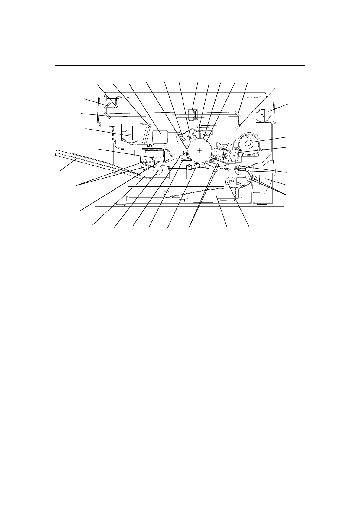
2. MECHANICAL COMPONENT LAYOUT
11
10
9
14
15
13
16
17
18
19
21 22 23
20
24 25
26
27
28
29
12
30
31
32
33
8
7
6
45
3
2
1
1. Semicircular Feed Rollers
2. Paper Tray
3. Registration Rollers
4. Transfer and Separation
Corona Unit
5. Pick-off Pawl
6. Cleaning Unit
7. Pressure Roller
8. Fusing Unit
9. Hot Roller
10. Exit Rollers
11. Copy Tray
12. Hot Roller Strippers
13. Exhaust Blower Motor
14. 3rd Mirror
15. 2nd Mirror
16. 1st Mirror
17. Ozone Filter
18. Used Toner Tank
19. Cleaning Blade
20. Quenching Lamp
21. Charge Corona Unit
22. Lens
23. 6th Mirror
24. Erase Lamp
25. Drum
26. 4th Mirror
27. 5th Mirror
28. Optics Cooling Fan Motor
(FT3213 Copier only)
29. Toner Supply Unit
30. Development Unit
31. 2nd Relay Rollers
32. By-pass Feed Table
33. 1st Relay Rollers
STM 1-4 FT3013/3213
Page 12
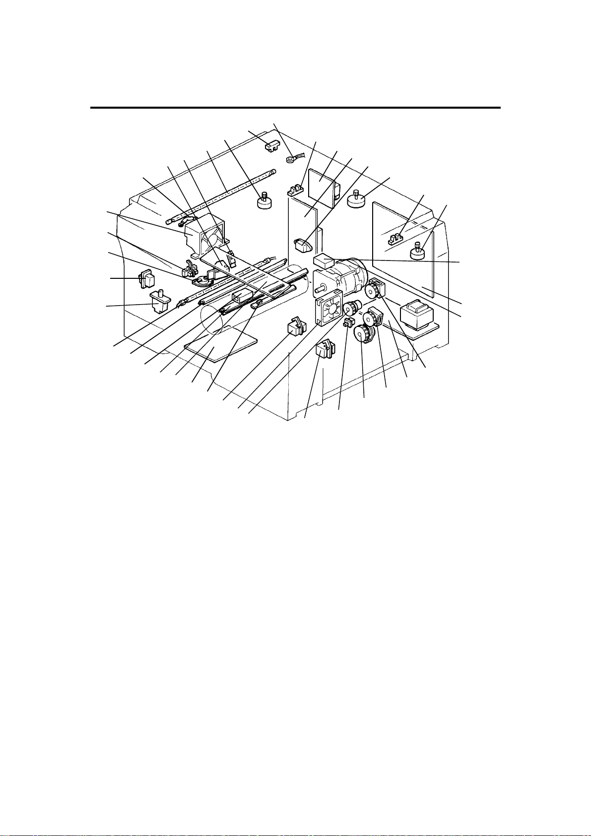
3. ELECTRICAL COMPONENT LAYOUT
17
16
15
13
14
12
11
18
10
9
19
24
23
22
21
20
25
26
27
28
29
30
31
32
33
34
8
7
6
5
4
3
2
1
37
38
35
36
1. Paper Tray Switch
2. Relay Sensor
3. Registration Clutch
4. Optics Cooling Fan Motor
(FT3213 only)
5. Registration Sensor
6. Image Density Sensor
7. Power Pack-TC/SC
8. Operation Panel Board
9. Erase Lamp
10. Total Counter
11. Quenching Lamp
12. Fusing Lamp
13. Front Cover Safety Switch
14. Main Switch
15. Fusing Thermoswitch
16. Exit Sensor
17. Exhaust Blower Motor
18. Optics Thermofuse
19. Auto Image Density Sensor
20. Fusing Thermistor
21. Exposure Lamp
22. Lens Motor
(FT3213 copier only)
23. Scanner Home Position
Sensor
24. Optics Thermistor
25. Lens Home Position
Sensor
(FT3213 copier only)
26. Power Pack-CC/Grid/Bias
27. AC Drive Board
28. Fusing Triac (115 V only)
29. Scanner Motor
30. 4th/5th Mirror Home
Position Sensor
(FT3213 copier only)
31. 4th/5th Mirror Motor
(FT3213 copier only)
32. Main Motor Capacitor
33. Main Board
34. Main Motor
35. Toner Supply Clutch
36. DC Power Supply Board
37. Relay Roller Clutch
38. Paper Feed Clutch
FT3013/3213 1-5 STM
Page 13

Rev. 1/95
4. ELECTRICAL COMPONENT DESCRIPTIONS
Motors
SYMBOL NAME FUNCTION
Drives all the main unit components except for the
M1 Main Motor
M2 Scanner Motor Drives the scanners (1st and 2nd). (dc stepper) 29
M3 Lens Motor
M4
M5
M6
4th/5th Mirror
Motor
Optics Cooling
Fan Motor
Exhaust Blower
Motor
optics unit and fans. (115/220--240 Vac [ac
synchronous])
Positions the lens according to the selected
magnification. (dc stepper)
… FT3213 copier only
Positions the 4th/5th mirrors according to the
selected magnification. (dc stepper)
… FT3213 copier only
Prevents a build up of hot air in the optics cavity.
(24 Vdc)
… FT3213 copier only
Removes heat from around the fusing unit and
moves the ozone built up around the charge
section to the ozone filter. (24 Vdc)
INDEX
NO.
34
22
31
4
17
Magnetic Clutch
SYMBOL NAME FUNCTION
MC1
Registration
Clutch
Drives the registration rollers. 3
Magnetic Spring Clutches
SYMBOL NAME FUNCTION
MSC1
MSC2
MSC3
Toner Supply
Clutch
Relay Roller
Clutch
Paper Feed
Clutch
Drives the toner supply roller. 35
Drives the 1st and 2nd relay rollers. 37
Starts paper feed. 38
INDEX
NO.
INDEX
NO.
STM 1-6 FT3013/3213
Page 14

Switches
SYMBOL NAME FUNCTION
SW1 Main Switch Supplies power to the copier. 14
SW2
SW3
Front Cover
Safety Switch
Paper Tray
Switch
Cuts the ac power line, when the front cover is
open.
Detects when the paper tray is set. 1
Sensors
SYMBOL NAME FUNCTION
S1
S2
S3
S4
S5 Exit Sensor Detects misfeeds. 16
S6 Relay Sensor
S7
S8
Scanner Home
Position Sensor
Lens Home
Position Sensor
4th/5th Mirror
Home Position
Sensor
Registration
Sensor
Image Density
(ID) Sensor
Auto Image
Density Sensor
(ADS)
Informs the CPU when the 1st scanner is at the
home position.
Informs the CPU when the lens is at the home
position (full size position).
… FT3213 copier only
Informs the CPU when 4th/5th mirrors assembly is
at the home position (full size position).
… FT3213 copier only
1) Detects misfeeds.
2) Controls the relay roller clutch stop timing.
1) Detects when copy paper is set on the
by-pass feed table.
2) Detects misfeeds.
Detects the density of the image on the drum to
control the toner density.
Senses the background density of the original. 19
INDEX
NO.
13
INDEX
NO.
23
25
30
5
2
6
Printed Circuit Boards
SYMBOL NAME FUNCTION
PCB1 Main Board
PCB2 AC Drive Board
PCB3
PCB4
FT3013/3213 1-7 STM
DC Power
Supply Board
Operation Panel
Board
Controls all copier functions both directly and
through the other PCBs.
Drives the main motor, exposure lamp, fusing
lamp, and quenching lamp.
Converts the wall outlet ac power input to +5 volts,
+24 volts, and a zero cross signal.
Informs the CPU of the selected modes and
displays the copier status and condition on the
panel.
INDEX
NO.
33
27
36
8
Page 15

Lamps
SYMBOL NAME FUNCTION
L1 Exposure Lamp
L2 Fusing Lamp Provides heat to the hot roller. 12
L3 Quenching Lamp
L4 Erase Lamp
Applies high intensity light to the original for
exposure.
Neutralizes any charge remaining on the drum
surface after cleaning.
Discharge the drum outside of the image area.
Provides leading/trailing edge erase and side
erase.
Power Packs
SYMBOL NAME FUNCTION
P1
P2
Power Pack
--CC/Grid/Bias
Power Pack
--TC/SC
Provides high voltage for the charge corona, grid,
and development roller.
Provides high voltage for the transfer and
separation corona.
Counter
SYMBOL NAME FUNCTION
CO1 Total Counter Keeps track of the total number of copies made. 10
INDEX
NO.
21
11
9
INDEX
NO.
26
7
INDEX
NO.
Others
SYMBOL NAME FUNCTION
TH1
TH2
TS
TF
C
TR Fusing Triac
Fusing
Thermistor
Optics
Thermistor
Fusing
Thermoswitch
Optics
Thermofuse
Main Motor
Capacitor
Monitors the fusing temperature. 20
Monitors the optics temperature. 24
Provides back-up overheat protection in the fusing
unit.
Provides back-up overheat protection around the
exposure lamp.
Start capacitor. 32
Switches the fusing lamp on and off. (115 V only)
Note: In the 220V-230V/240V version, the triac
is built-in the ac drive board
INDEX
NO.
15
18
28
STM 1-8 FT3013/3213
Page 16
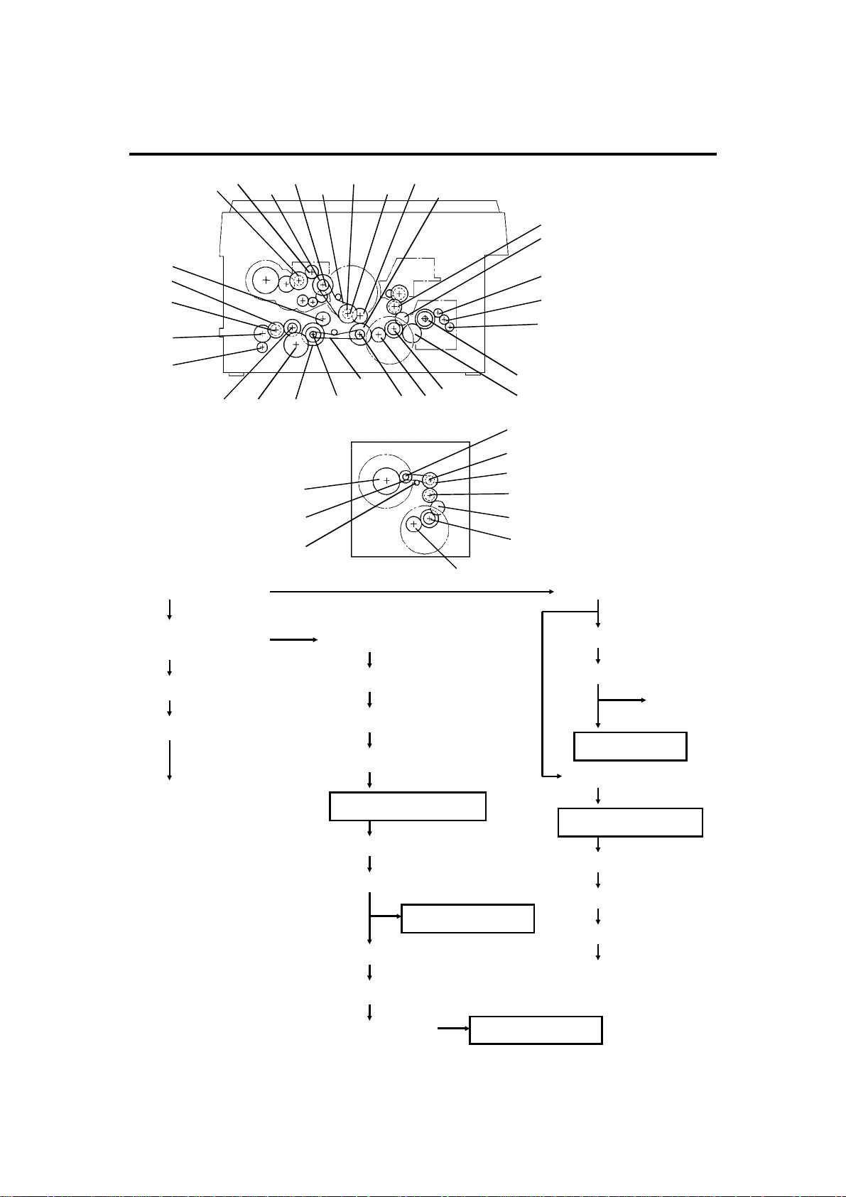
5. DRIVE LAYOUT
G14
G13
G15
G16
G17
G18
G19
G1: Main Motor Gear
BP6 BP5
G22 BP1G21G20
G26
G25
TB2
TB3
TB1
BP2
G12 G11
G10
G23
G2G1
G9
G8
G7
G6
G5
G4
G3
BP4
BP3
G24
G9
G8
G2
G1
G2: Relay Gear
G23: Timing Belt Drive
Gear
BP1: Timing Belt Pulley
TB1: Timing Belt
A
G10 Relay gear
G11: Timing Belt Drive Gear
BP5: Timing Belt Pulley
TB3: Timing Belt
Development Section
BP6: Timing Belt Pulley
G12: Development Gear
Development Unit
G13: Relay Gear
G14: Toner Supply CL Gear
Toner Supply CL
Toner Supply Unit
G8: Relay Gear
G9: Relay Gear
B
Cleaning Unit
G3: Fusing Drive Gear
Fusing and Exit Unit
G4: Hot Roller Gear
G7: Relay Gear
G6: Relay Gear
G5: Exit Roller Gear
FT3013/3213 1-9 STM
Page 17
A
B
G15: Registration CL
Gear
Registration CL
Registration Rollers
G20: Relay Gear
G17: Relay Roller CL
Gear
Relay Roller CL
G16: 2nd Relay Roller
Gear
2nd Relay Rollers
Paper Feed Section
BP2: Timing Belt Pulley
G22: Relay Gear
Paper Feed Section
G21: Paper Feed CL
Gear
Paper Feed CL
Feed Rollers
G24: Timing Belt Drive
Gear
BP3: Timing Belt Pulley
TB2: Timing Belt
BP4: Timing Belt Pulley
G25: Relay Gear
G26: Drum Drive Gear
G18: Relay Gear
G19: 1st Relay Roller
Gear
1st Relay Rollers
STM 1-10 FT3013/3213
Page 18
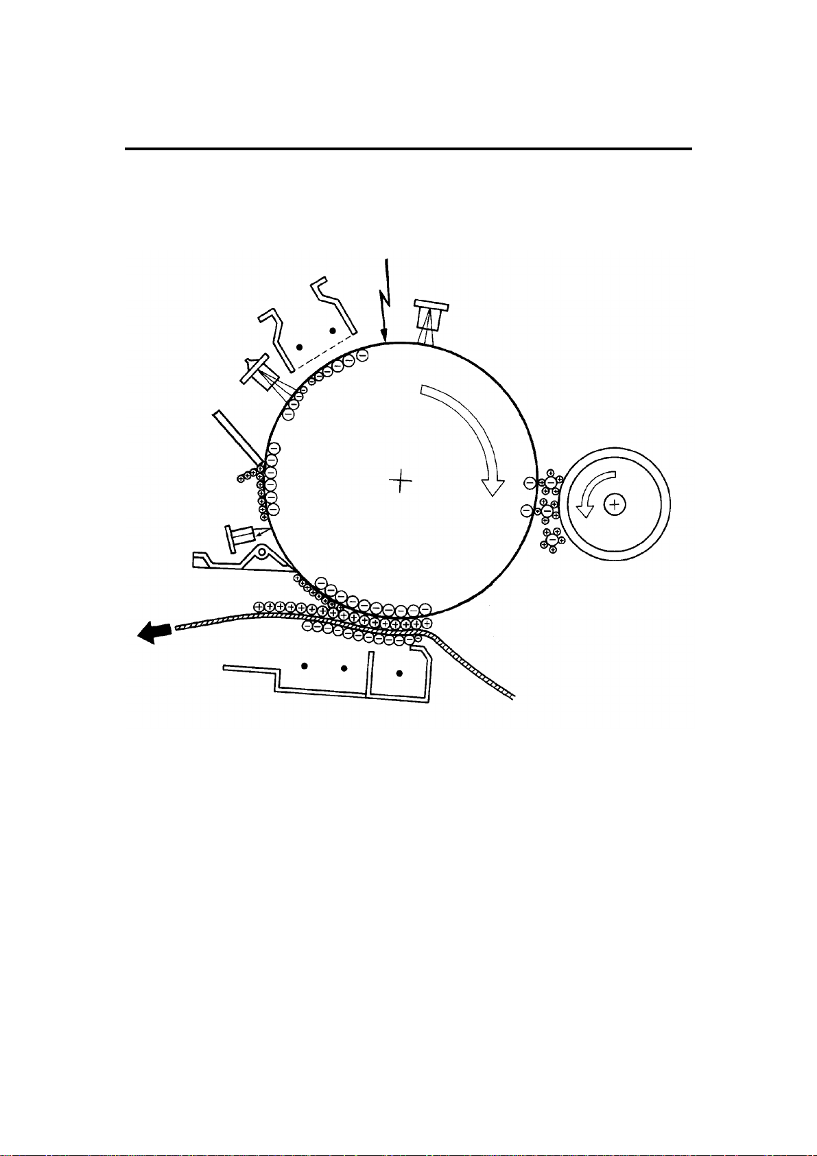
6. COPY PROCESSES AROUND THE DRUM
2. EXPOSURE
1. DRUM CHARGE
3. ERASE
8. QUENCHING
4. DEVELOPMENT
7. CLEANING
6. PAPER
SEPARATION
FT3013/3213 1-11 STM
5. IMAGE TRANSFER
Page 19

1. DRUM CHARGE
In the dark, the charge corona unit gives a uniform negative charge to the organic
photoconductive (OPC) drum. The charge remains on the surface of the drum because the
OPC drum has a high electrical resistance in the dark.
2. EXPOSURE
An image of the original is reflected to the OPC drum surface via the optics assembly. The
charge on the drum surface is dissipated in direct proportion to the intensity of the reflected
light, thus producing an electrical latent image on the drum surface.
3. ERASE
The erase lamp illuminates the areas of the charged drum surface that will not be used for
the copy image. The resistance of the drum in the illuminated areas drops and the charge on
those areas dissipates.
4. DEVELOPMENT
Positively charged toner is attracted to the negatively charged areas of the drum, thus
developing the latent image. (The positive triboelectric charge is caused by friction between
the carrier and toner particles.)
5. IMAGE TRANSFER
Paper is fed to the drum surface at the proper time so as to align the copy paper and the
developed image on the drum surface. Then, a strong negative charge is applied to the back
side of the copy paper, producing an electrical force which pulls the toner particles from the
drum surface to the copy paper. At the same time, the copy paper is electrically attracted to
the drum surface.
6. PAPER SEPARATION
A strong ac corona discharge is applied to the back side of the copy paper, reducing the
negative charge on the copy paper and breaking the electrical attraction between the paper
and the drum. Then, the stiffness of the copy paper causes it to separate from the drum
surface. The pick-off pawl help to separate the paper from the drum.
7. CLEANING
The cleaning blade removes any toner remaining on the drum.
8. QUENCHING
Light from the quenching lamp electrically neutralizes the surface of the drum.
STM 1-12 FT3013/3213
Page 20

7. COPY PROCESS CONTROL
Image
Density
Control
Toner
Density
Detection
Residual
Voltage
(Vr)
Detection
Between
Copies
Grid Voltage
Standard image
density grid voltage
(--680 V)
+ + +
Drum residual voltage
(Vr) correction factor
(SP67)
+
Auto image density
level factor (SP34)
Standard ID sensor
grid voltage
(--460 V)
+
Drum wear correction
factor (SP57)
Standard ID sensor
grid voltage
(--460 V)
+
Drum wear correction
factor (SP57)
0 Volts (Fixed) Exposure lamp turns off --160 Volts (Fixed)
Exposure Lamp
Voltage
Base exposure lamp
voltage (Manual or ADS
mode) (SP48)
VL correction factor
+
Reproduction ratio
correction factor
(FT3213 copier only)
Same as image density
control
Same as image density
control
Development Bias
Voltage
Base bias voltage factor
(Manual or ADS mode
[SP34])
Image bias voltage
adjustment factor
(SP37)
+
Drum residual voltage
(Vr) correction factor
Note:
Base bias voltage at
manual ID level 7 can be
adjusted by SP50
Depends on ID sensor
bias setting (SP33)
Note:
For initial 499 copies
bias voltage is increased
by --20 volts
0 Volts (Fixed) Full erase
+
Image bias voltage
adjustment factor
(SP37)
+
Drum residual voltage
(Vr) correction factor
Erase Lamp
Depends on
paper size
and
reproduction
ratio
ID sensor
pattern erase
(Vsg
detection:
Full erase)
(All LEDs ON)
Full erase
(All LEDs ON)
NOTE: The boxed items can be adjusted by SP mode.
FT3013/3213 1-13 STM
Page 21
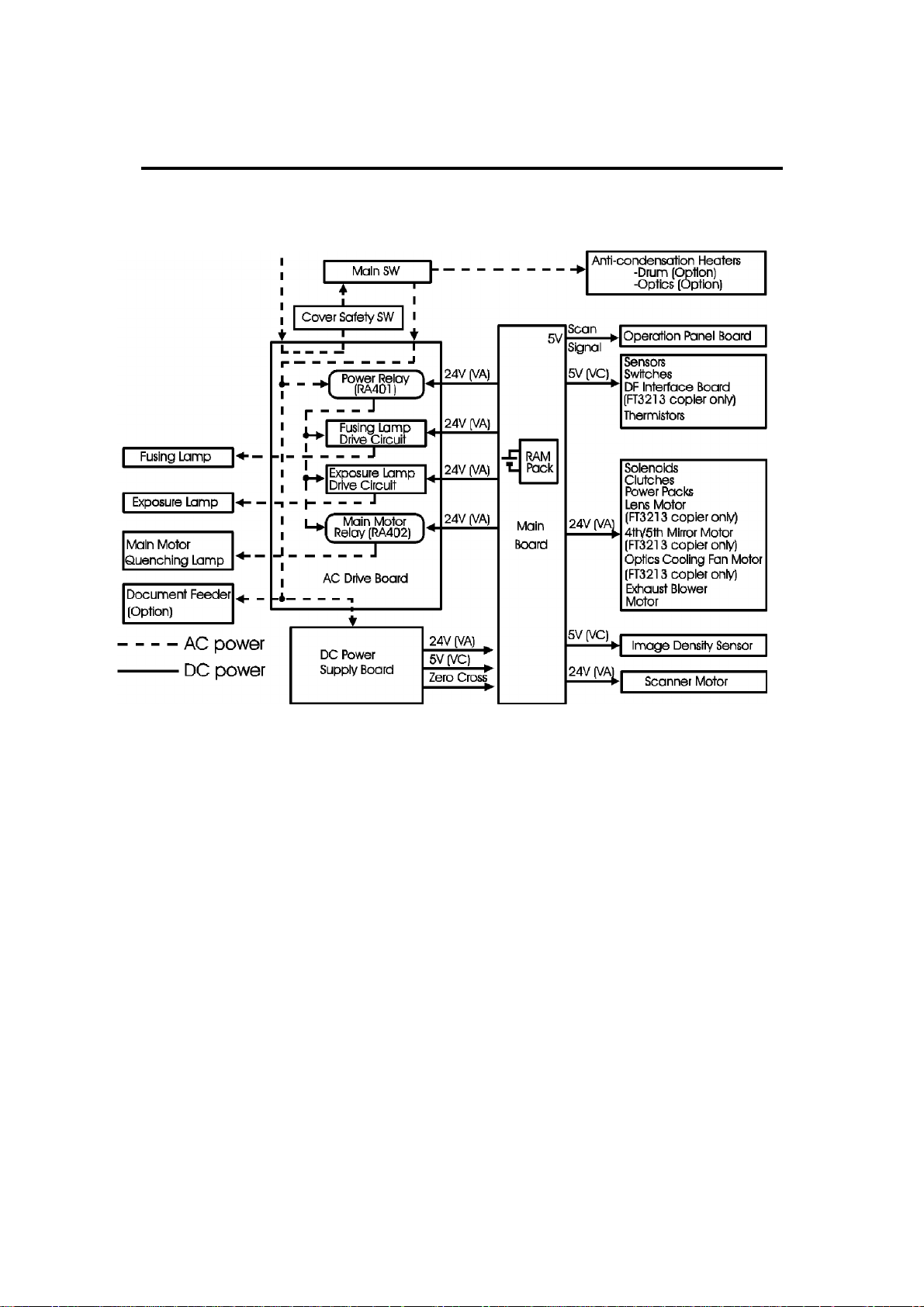
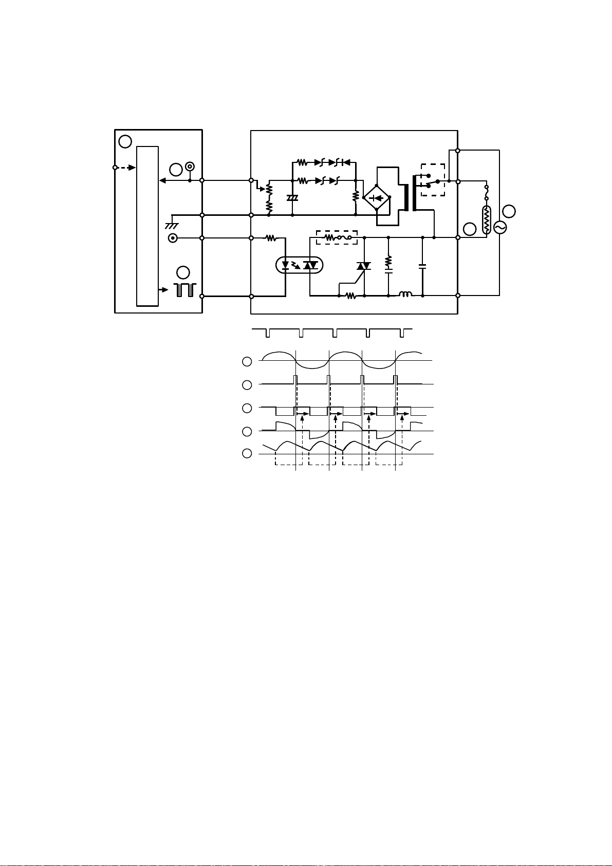
8. POWER DISTRIBUTION
AC Power (115V)
When this copier is plugged in and the main switch is turned off, ac power is
supplied via the ac drive board to the optional anti-condensation heaters.
When the front cover and/or the exit cover is open, the cover safety switch
completely cuts off power to all ac and dc components. The RAM pack has a
back up power supply (dc battery) for the service program mode data and
misfeed job recovery.
When the main switch is turned on, the ac power supply to the
anti-condensation heater is cut off and ac power is supplied to the ac drive
board. The dc power supply board receives wall outlet ac power through the
ac drive board.
The dc power supply board converts the wall outlet ac power input to +5
volts, +24 volts, and a zero cross signal, all of which are supplied to the main
board.
STM 1-14 FT3013/3213
Page 22

The main board supplies dc power to all copier dc components. All sensors,
switches, thermistors, and the DF interface board (option) operate on +5
volts. The operation panel operates on +5 volts supplied by the main board.
All other dc components including the power relay (RA401) and the main
motor relay (RA402) operate on +24 volts.
When the main board receives power, it activates the power relay (RA401)
which then supplies ac power to the fusing lamp drive circuit, and the
exposure lamp drive circuit on the ac drive board. The fusing lamp drive
circuit receives a trigger signal from the main board and the fusing lamp
lights. The exposure lamp does not turn on until the main board sends a
trigger pulse to the exposure lamp drive circuit.
When the Start key is pressed, the main board energizes the main motor
relay (RA402). Then, the main motor and the quenching lamp turn on.
When the main switch is turned off, power is cut off to the main board and to
RA401, and the optional drum and optics anti-condensation heaters are
turned on.
FT3013/3213 1-15 STM
Page 23

Page 24

SECTION 2
DETAILED SECTION
DESCRIPTIONS
Page 25

Page 26

1. DRUM
1.1 DRUM CHARACTERISTICS
An organic photoconductor (OPC) drum is used in this model.
The OPC drum has the characteristics of:
1. Being able to accept a high negative electrical charge in the dark. (The
electrical resistance of a photoconductor is high in the absence of light.)
2. Dissipating the electrical charge when exposed to light. (Exposure to light
greatly increases the conductivity of a photoconductor.)
3. Dissipating an amount of charge in direct proportion to the intensity of the
light. That is, where stronger light is directed to the photoconductor
surface, a smaller voltage remains on the drum.
4. Being less sensitive to changes in temperature (when compared to
selenium F type drums).
5. During the drum’s life, drum residual voltage gradually increases and the
photoconductive surface becomes worn.
Therefore, some compensation for these characteristics is required.
FT3013/3213 2-1 STM
Page 27

1.2 DRUM UNIT
[A]
[E]
[G]
[F]
[C]
[D]
[B]
[C]
The drum unit [A] consists of an OPC drum [B], ID sensor board [C] and a
pick-off pawl [D]. When the drum, the pick-off pawl, or the ID sensor is
replaced or cleaned, the drum unit must be removed from the copier.
Therefore, the drum has a coupling device which is connected to the drum
drive gear [E]. The ID sensor connector [F] is used for the ID sensor.
The main motor provides rotation directly to the drum through a series of
gears.
The pick-off pawl [D] is always in contact with the drum surface.
[D]
STM 2-2 FT3013/3213
Page 28
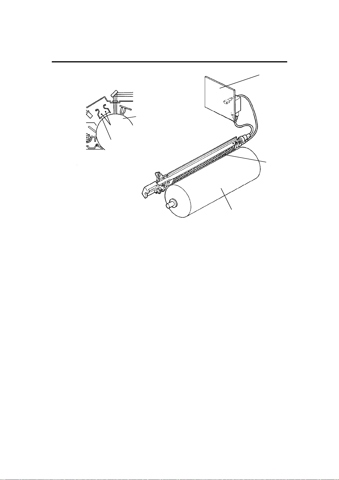
2. DRUM CHARGE
2.1 OVERVIEW
[A]
[B]
[D]
[A]
This copier uses a double wire scorotron and a highly sensitive OPC drum
[A]. The corona wires [B] generate a corona of negative ions when the
CC/Grid/Bias power pack [C] applies a high voltage. The CC/Grid/Bias power
pack also applies a negative high voltage to a stainless steel grid plate [D].
This insures that the drum coating receives a uniform negative charge as it
rotates past the corona unit.
[C]
[D]
The exhaust fan, located above the copy exit, causes a flow of air from the
upper area of the development unit through the charge corona unit. This
prevents an uneven build-up of negative ions that can cause uneven image
density. The exhaust fan runs at half speed when in the stand-by condition
and at full speed while copying.
The exhaust fan has an ozone filter (active carbon) which adsorbs ozone (O3)
generated by the charge corona. The ozone filter decreases in efficiency over
time as it adsorbs ozone. The ozone filter should be replaced at every 80K
copies.
The flow of air around the charge corona wires may deposit paper dust or
toner particles on the corona wire. These particles may interfere with
charging and cause low density bands on copies. To help prevent this, a wire
cleaner cleans the corona wire when the operator slides the corona unit out
and in.
FT3013/3213 2-3 STM
Page 29

2.2 CHARGE CORONA WIRE CLEANER MECHANISM
[B]
[A]
[D]
Pads [A] above and below the charge corona wires clean the wires as the
charge unit is manually slid in and out.
The cleaner pad bracket [B] rotates when the charge unit is fully extended
and the bracket is pulled up against the rear endblock [C]. This moves the
pads against the corona wires (see illustration). If the charge unit is not fully
extended, the pads do not touch the corona wires.
The pads move away from the wires when the charge unit is fully inserted
and the cleaning bracket is pushed against the front endblock [D].
After copier installation the key operator should be instructed to use this
mechanism when copies exhibit white streaks, (low image density bands).
[C]
STM 2-4 FT3013/3213
Page 30
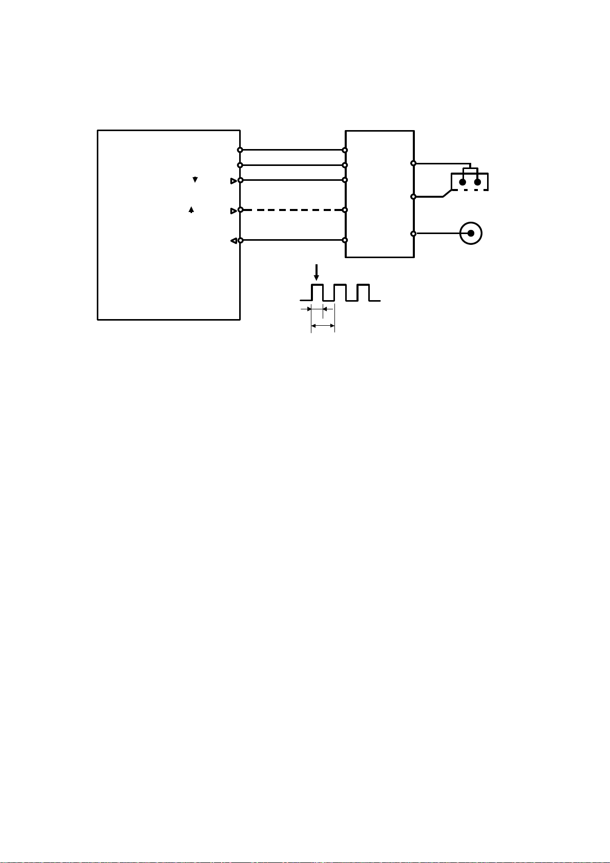
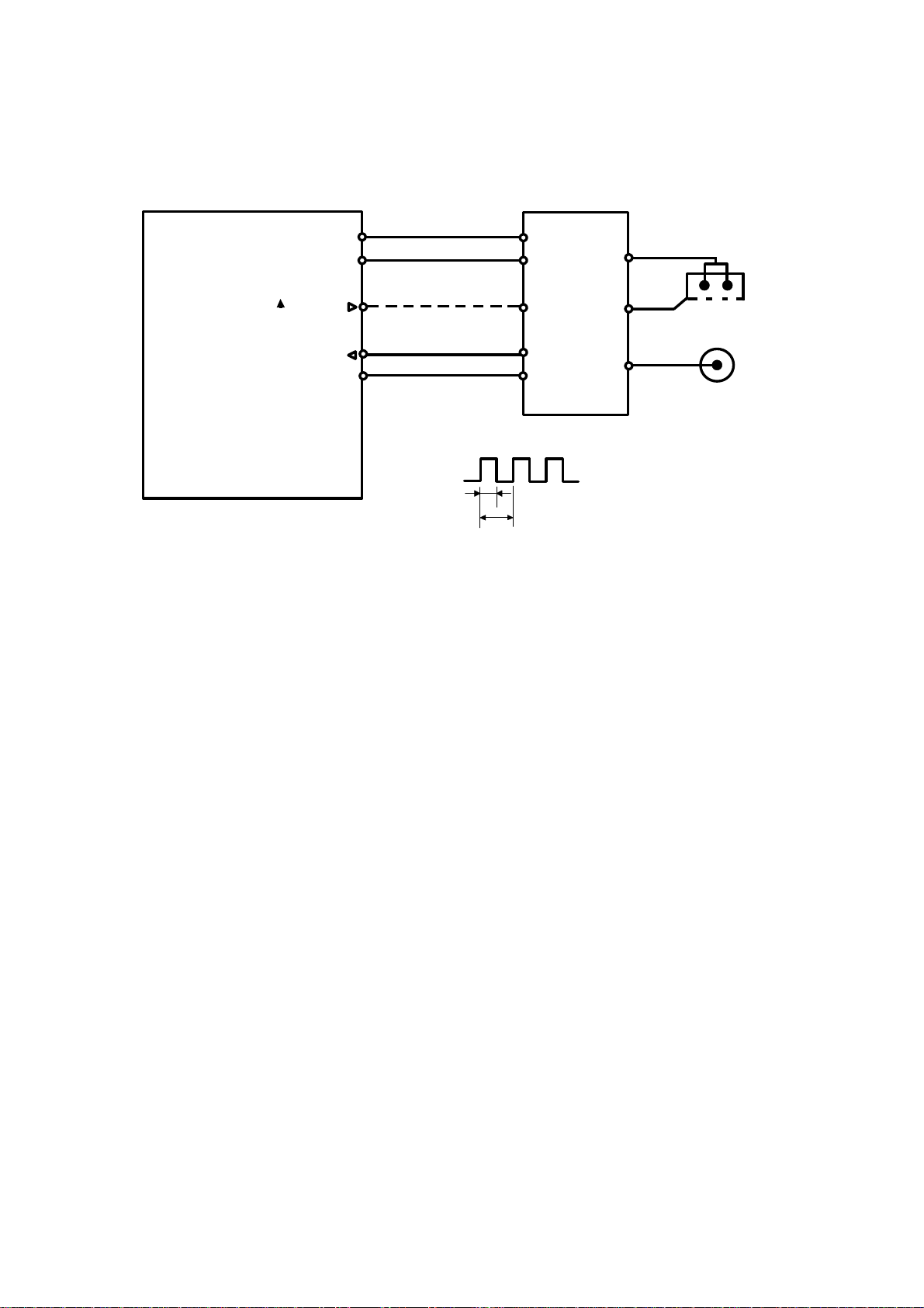
2.3 CHARGE CORONA CIRCUIT
t2
CN1-1
CN1-2
CN1-3
CN1-5
CN1-7
t1
Power Pack CC/Grid/Bias
(P1)
PWM Duty cycle
=t2/t1 x 100 (%)
Charge Corona
C
G
B
Development
Bias
Grid
VA [24]
VC [5]
CC Trig [ 24]
Grid Trig (PWM) [ 0→0/5]
GND [0]
Main Board (PCB 1)
CN119-7
CN119-6
CN119-5
CN119-3
CN119-1
The main board supplies +24 volts to the CC/Grid/Bias power pack at CN1-1
as the power supply source. After the Start key is pressed the CPU drops
CN1-3 from +24 volts to 0 volts. This energizes the charge corona circuit
within the CC/Grid/Bias power pack, which applies a high negative voltage of
approximately --7.0 K volts to the charge corona wires. The corona wires then
generate a negative corona charge.
The grid plate limits the charge voltage to ensure that the charge does not
fluctuate and that an even charge is applied to the drum surface.
The grid trigger pulse applied to CN1-5 is a pulse width modulated signal
(PWM signal). This signal is not only a trigger signal, it also changes the
voltage level of the grid. As the width of the pulse applied increases (see
arrow in above illustration), the voltage of the grid also increases (becomes
more negative).
FT3013/3213 2-5 STM
Page 31

2.4 GRID VOLTAGE CORRECTION
To maintain good copy quality over the drum’s life, the grid voltage is
changed due to the following:
• Drum residual voltage correction (Vr correction)
• Drum wear correction
2.4.1 Drum Residual Voltage Correction (Vr correction)
During the drum’s life, the drum may fatigue electrically and residual voltage
(Vr) on the drum may gradually increase. When this happens, the corona
charged voltage on the drum is not discharged enough in the quenching and
exposure processes. Even though development bias is applied during the
development process, the background area of the original on the drum may
still attract some toner. This may cause dirty background on copies. The Vr
correction prevents this phenomenon as follows:
A pattern (Vr pattern) is developed on the drum every 1,000 copies and its
reflectivity is detected by the ID sensor to measure the residual voltage. This
is called residual voltage detection. (If the reflectivity is low, the residual
voltage will be high.) When the Vr pattern is developed, all blocks of the
erase lamp turn on, and the development bias voltage is 0 volt.
The CPU determines what level of Vr correction is necessary depending on
the output (Vr ratio [L]) from the ID sensor.
Vrp
L =
x 100 (%)
Vsg
Vrp: ID sensor output for Vr pattern
Vsg: ID sensor output for bare drum
The current Vr ratio is displayed by SP67.
The CPU increases the development bias voltage depending on the Vr ratio
to prevent dirty background on copies, (See page 2-30 for more information.)
The CPU also increases the grid voltage to ensure proper image density
depending on the Vr ratio. (See page 2-8.)
STM 2-6 FT3013/3213
Page 32

Rev. 1/95
2.4.2 Drum Wear Correction
During the drum’s life, the photoconductive surface of the drum becomes
worn by contact with the cleaning blade and developer on the development
roller. This effects the ability of the drum to hold a charge. This characteristic
especially affects the development of the ID sensor pattern. The ID sensor
pattern developed on the drum becomes lighter causing higher toner
concentration in the developer. The drum wear correction is made to prevent
this phenomenon and is as follows:
The CPU keeps track of the drum’s rotation time that corresponds to the wear
of the photoconductive layer. The grid voltage for the toner density detection
increases at a set interval. The grid voltage for the residual voltage (Vr)
detection also increases at the same interval. (See page 2-9.) The drum
rotation time is displayed by SP57.
2.5 GRID VOLTAGE FOR IMAGE DENSITY CONTROL
The main board controls the grid voltage for the copy image through the
CC/Grid/Bias power pack. As the grid voltage for the image density control
becomes less, the copy image becomes lighter and vice versa.
The grid voltage is based on the standard grid voltage and correction factors
as follows:
Grid Voltage = Standard image density grid voltage (--680 volts [SP60 = 4])
+
Vr correction factor
+
Auto image density level factor (SP34)
2.5.1 Standard Image Density Grid Voltage
The standard image density grid voltage (SP60) is set at the factory and the
setting is different for each machine. The setting of SP60 is described on the
SP mode data sheet located inside the inner cover of the machine.
FT3013/3213 2-7 STM
Page 33

2.5.2 Drum Residual Voltage (Vr) Correction Factor
Vr ratio (L) (%) (SP67) Change of grid voltage (volts)
100 to 84 ±0
83 to 58 --40
57 to 41 --80
40 to 28 --120
27 to 0 --160
L = Vrp/Vsg x 100 (%)
Vrp: ID sensor output for Vr pattern
Vsg: ID sensor output for bare drum
During the drum’s life, drum residual voltage (Vr) may gradually increase. Vr
correction compensates for the residual voltage on the drum. The Vr
correction is done every 1000 copies. The CPU increases the development
bias voltage and the grid voltage. The above table shows how the grid
voltage changes depending on the Vr ratio.
2.5.3 Auto Image Density Level Factor (SP34)
Auto image density level Data (SP34) Change of grid voltage (volts)
Normal 0 * ±0
Darker 1 --40
Lighter 2 ±0
* Factory setting
The grid voltage and the exposure lamp voltage are constant regardless of
the output from the auto image density sensor. Only the development bias
voltage varies depending on the output from the auto image density sensor.
However, when the auto image density level data in SP34 is set to darker,
the grid voltage is changed --40 volts as shown in the above table. When it is
set to lighter, the grid voltage does not change, in this case the development
bias voltage is corrected.
STM 2-8 FT3013/3213
Page 34

2.6 GRID VOLTAGE FOR TONER DENSITY DETECTION AND
RESIDUAL VOLTAGE (Vr) DETECTION
The grid voltage is the same for both toner density detection and residual
voltage correction.
Grid voltage = Standard ID sensor grid voltage (--460 volts [SP62=4])
+
Drum wear correction factor (SP57)
Drum Wear Correction Factor (SP57)
Main motor rotation time (SP57) Change of grid voltage (volts)
0 to 2H ±0
2 to 65H --20
65 to 112H --40
112 to 157H --60
More than 157H --80
The grid voltage for toner density detection is the same as it is for the
residual voltage (Vr) detection. However, the development bias voltage is
different. (See pages 2-30 and 2-35.)
FT3013/3213 2-9 STM
Page 35

3. OPTICS
3.1 OVERVIEW
[B]
[C]
[D]
During the copy cycle, an image of the original is reflected onto the drum
surface through the optics assembly as follows.
Light Path:
Exposure Lamp [A] → Original → First Mirror [B] → Second Mirror [C]
→ Third Mirror [D] → Lens [E] → Fourth Mirror [F]→ Fifth Mirror [G]
→ Sixth Mirror [H] → Drum [I]
[A]
[E] [H] [F] [J]
[I]
[G]
This copier has six standard reproduction ratios (FT3213 copier only), three
reduction ratios, two enlargement ratios, and full size. It also has a zoom
function. The operator can change the reproduction ratio in one percent steps
from 61% to 141%.
Stepper motors are used to change the positions of the lens and mirrors
(FT3213 copier only). Separate motors are used because the wide range of
reproduction ratios makes it mechanically difficult for one motor to position
both the lens and mirrors. A stepper motor is also used to drive the scanner.
This motor changes the scanner speed according to the reproduction ratio.
STM 2-10 FT3013/3213
Page 36

The CPU monitors the temperature around the optics cavity through a
thermistor which is located at the upper left rear side of the copier frame.
When the temperature reaches 45°C, the optics cooling fan [J] (FT3213
copier only) starts rotating to draw cool air into the optics cavity. However, the
FT3013 copier is not equipped with a cooling fan. The machine will stop if the
optics cavity overheats. (See page 6-52.) In this case, the Energy Saver
indicator blinks and the Start key turns red.
The air flows from the right to the left, and exhausts through the vents in the
left side of the upper cover. This fan operates until the temperature drops
below 45°C.
The thermofuse provides back-up overheat protection. It opens at 128°C and
removes ac power to the exposure lamp.
FT3013/3213 2-11 STM
Page 37

3.2 SCANNER DRIVE
[E]
[B]
[D]
[F]
[C]
[A]
3.2.1 1st and 2nd Scanner Drive Mechanism
This model uses a stepper motor [A] to drive the scanners. Both ends of each
scanner are driven to prevent skewing. The scanners have sliders [B], which
ride on guide rails.
The scanner home position is detected by the home position sensor [C]. The
scanner return position is determined by counting the scanner motor drive
pulses.
The first scanner [D], which consists of the exposure lamp and the first mirror,
is connected to the scanner drive wire by the wire clamps [E]. The second
scanner [F], which consists of the second and third mirrors, is connected to
the scanner drive wire by movable pulleys (the second scanner pulleys [G]).
The pulleys move the second scanner at half the velocity of the first scanner.
This maintains the focal distance between the original and the lens during
scanning. This relationship can be expressed as:
V1r = 2 (V2r) = VD/r
where r = Reproduction ratio
V1r = First scanner velocity (when the reproduction ratio
is "r")
V2r = Second scanner velocity (when the reproduction ratio
is "r")
VD = Drum peripheral velocity (100 mm/s)
[G]
STM 2-12 FT3013/3213
Page 38

3.3 LENS DRIVE (FT3213 copier only)
[C]
[D]
[B]
[A]
: Reduction
: Enlargement
3.3.1 Lens Drive
The lens motor [A] (a stepper motor) changes the lens [B] position through
the lens drive wire [C] in accordance with the selected reproduction ratio to
provide the proper optical distance between the lens and the drum surface.
The rotation of the lens drive pulley moves the lens back and forth in discrete
steps. The home position of the lens is detected by the home position sensor
[D]. The main board keeps track of the lens position based on the number of
pulses sent to the lens motor.
FT3013/3213 2-13 STM
Page 39

3.3.2 Lens Positioning
[A]
[D]
[C]
[B]
Home Position (100%)
(100% → 129%)
(129% → 65%)
(65% → 93%)
(93% → 65%)
(65% → 129%)
(129% → 121%)
(121% → 129%)
(121% → 100%)
(100% → 65%)
(65% → 100%)
Reduction SideEnlargement Side
The lens home position sensor [A] informs the main board when the lens is at
the full size position (home position). The main board determines the lens
stop position in reduction and enlargement modes by counting the number of
steps the motor makes with reference to the lens home position. When a new
reproduction ratio is selected, the lens [B] moves directly to the selected
magnification position.
The lens home position is registered each time the lens starts from or passes
through the lens home position sensor. As the lens moves from the
enlargement side to the reduction side, the sensor registers the home
position. This occurs when the actuator plate [C] enters the lens home
position sensor.
A small vibration can be observed when the lens moves through home
position from the reduction side to the enlargement side because the lens is
going in the wrong direction to register the home position. The lens
overshoots the home position by only one pulse before going back to register
the home position.
The lens always stops while moving from left to right (as viewed from the
front) to minimize the error caused by mechanical play in the drive gears [D].
STM 2-14 FT3013/3213
Page 40

3.4 4TH/5TH MIRROR DRIVE (FT3213 copier only)
[B]
[A]
Home Position (100%)
(100% → 129%)
(129% → 65%)
(65% → 93%)
(93% → 65%)
(65% → 129%)
(129% → 121%)
(121% → 129%)
(121% → 100%)
(100% → 65%)
(65% → 100%)
3.4.1 Drive
The 4th/5th mirror drive motor (a stepper motor) changes the 4th/5th mirror
assembly position through the pinion gears [A] and the rack gear [B] in
accordance with the selected reproduction ratio to provide the proper optical
distance between the lens and drum surface.
3.4.2 Positioning
The positioning mechanism is similar to that of lens positioning, as shown in
the above positioning chart. The 4th/5th mirror assembly always stops while
moving from right to left (as viewed from the front).
FT3013/3213 2-15 STM
Page 41

3.5 AUTOMATIC IMAGE DENSITY SENSING
[A]
[C]
[B]
Sampled area
70 mm
a
b
Light from the exposure lamp is reflected from the original and travels to the
lens [A] via the mirrors. The auto ID sensor [B], a photodiode, is mounted on
the upper front frame. The sensor cover [C] has a hole in it to allow light to
fall directly onto the sensor. Sampling starts 10 millimeters from the leading
edge of the original and continues for 50 millimeters from the leading edge of
original in full size mode. The length of "a" and "b" will vary depending on the
selected reproduction ratio (FT3213 copier only).
The lengths "a" and "b" in each reproduction ratio are calculated as follows:
a =
10 mm
Reproduction Ratio (%)
x 100 b =
Reproduction Ratio (%)
50 mm
x 100
The photosensor circuit converts the light intensity to a voltage. The detected
voltage is amplified and sent to the main PCB where it is digitized. The CPU
stores the digital value of each sampled point in RAM. It then computes the
image density of the original from the maximum sampled value and changes
the development bias accordingly. (See page 2-28 for details.) The exposure
lamp voltage is constant regardless of the image density of the original.
STM 2-16 FT3013/3213
Page 42

3.6 EXPOSURE LAMP VOLTAGE CONTROL
The main board controls the exposure lamp voltage through the ac drive
board. The exposure lamp voltage is based on the base lamp voltage and
various correction factors. The method of control is different depending on
whether the image density is manually selected or the auto image density
mode is selected.
The exposure lamp voltage consists of the following factors:
Exposure lamp voltage = Base exposure lamp voltage
(Manual or auto image density mode)
+
VL correction factor
+
Reproduction ratio correction factor
(FT3213 copier only)
3.6.1 Base Lamp Voltage In Manual Image Density Mode
Manual ID Level
Exposure Lamp Data
Darker Lighter
1 2 3 4 5 6 7
Vo --4 Vo --4 Vo --2 Vo ±0 Vo+2 Vo+2 Vo+4
The above table shows changes in the exposure lamp data in the manual
image density mode.
SP48 sets the exposure lamp data for level 4 (Vo) of manual image density
mode. A value from 100 to 150 can be selected.
3.6.2 Base Lamp Voltage In Auto Image Density Mode
In the auto ID mode, the CPU selects the level 4 (Vo) exposure lamp data
(SP48) regardless of the input from the auto image density sensor.
FT3013/3213 2-17 STM
Page 43

3.6.3 VL Correction Factor
The light intensity may decrease because of dust accumulated on the optics
parts. This may cause dirty background on copies. To compensate for this
occurance, VL correction is done as follows:
Whenever SP56 (ADS reference voltage adjustment) is performed, before
sampling starts for the ADS adjustment, the auto ID sensor measures the
amount of light reflected through the 1st, 2nd and 3rd mirrors from the white
plate located under the left frame. The photosensor circuit converts this light
intensity to a voltage. This voltage is then digitized and the CPU stores the
digital value in memory as the initial data.
The copier utilizes a software counter for the VL correction. At every 500
copies the machine measures the light intensity reflected from the white
plate, "new" value is then compared with the initial data stored in memory.
If the measured voltage difference is equal to or more than 0.1 volts, +1 will
be added to the exposure lamp data as the VL correction factor.
If the difference is less than 0.1 volts, no correction will be applied.
The total increase for VL correction cannot exceed +20. After cleaning the
optics section, the following actions must be performed in order.
• SP95: Clear the exposure lamp data and the software counter
by entering "1".
• SP48: Perform the light intensity adjustment.
• SP56: Perform the ADS adjustment (to store the new initial
data and to adjust the ADS reference voltage.)
3.6.4 Reproduction Ratio Correction Factor (FT3213 copier only)
Reproduction ratio (%) Change of exposure lamp data
61 and 62 +2
63 to 119 ±0
120 to 129 +2
130 to 141 +4
The exposure lamp data is increased depending on the selected
magnification ratio in order to compensate for the change in the concentration
of light on the drum.
STM 2-18 FT3013/3213
Page 44
3.7 EXPOSURE LAMP CONTROL CIRCUIT
Main Board (PCB1)
B
Zero
Cross
CN107-1
CPU
TP111
(EXPO)
E
Feed back
signal
0V
+24V
C
24V
0V
Trigger Pulse
AC power
Zero cross
Trigger pulse
CN114-2
CN114-1
CN114-7
CN114-3
CN401-7
CN401-8
CN401-2
CN401-6
AC Drive Board (PCB2)
T402
CN419-1
Thermofuse (TF)
Exposure
Lamp
D
CN419-2
T407
(L1)
A
AC115V
AC220V
AC240V
R401
VR401
R403
PC401
R404
R405
C401
ZD
401ZD402
ZD
403ZD404
R411
TRC401
D401
R406
R413
D404
~D407
CR401
L401
L402
CN421
240V
220V
220V Only
TR401
C411
A
B
C
Lamp power
Feedback
signal
D
E
Feedback
The main board sends lamp trigger (LOW signal) pulses to the ac drive board
from CN114-3. PC401 activates TRC401, which provides ac power to the
exposure lamp, at the lead edge of each trigger pulse.
The voltage applied to the exposure lamp is also provided to the feedback
circuit. The feedback circuit steps down (TR401), rectifies (D404 ∼ 407), and
smoothes (zener diodes and capacitors) the lamp voltage. The CPU monitors
the lowest point of the smoothed wave (feedback signal), which is directly
proportional to the actual lamp voltage.
The CPU changes the timing of the trigger pulses in response to the
feedback voltage. If the lamp voltage is too low, the CPU sends the trigger
pulses earlier so that more ac power is applied to the exposure lamp. This
feedback control is performed instantly; so, the lamp voltage is always stable
even under fluctuating ac power conditions.
The voltage applied to the exposure lamp can be changed with SP48 (Light
Intensity Adjustment). The ADS voltage adjustment (SP56) must be done
whenever the light intensity adjustment is done.
FT3013/3213 2-19 STM
Page 45

4. ERASE
4.1 OVERVIEW
[A]
LE
EL
[B]
SE
ES
LO
LC
LE: Lead edge erase margin 2.5 ±1.5 mm
SE: Side erase margin 2.0 ±2.0 mm on each side;
total of both sides 4 mm or less
LO: Original width
LC: Charged width of drum
EL: Lead edge erase
ES: Side erase (FT3213 copier only)
The erase lamp [A] consists of a single row of LEDs (29 LEDs) extending
across the full width of the drum [B].
The erase lamp has the following functions: lead edge erase, side erase
(FT3213 copier only), and trail edge erase.
STM 2-20 FT3013/3213
Page 46

a b c d e
h
g
f c
abde
4.1.1 Lead Edge Erase
The entire line of LEDs turn on when the main motor turns on. They stay on
until the erase margin slightly overlaps the lead edge of the original image
area on the drum (Lead Edge Erase Margin). This prevents the toner density
sensor pattern from being developed every copy cycle and the shadow of the
original edge from being developed on the paper. At this point, side erase
starts (FT3213 copier only). The width of the lead edge erase margin can be
adjusted using SP41.
During the toner density detection cycle (once every ten copy cycles), a block
of erase lamps (labeled "g" above) turns off long enough for the sensor
pattern to be developed.
The entire line of LEDs turn on when the residual voltage on the OPC drum is
being detected (Vr detection).
4.1.2 Side Erase
Based on the combination of copy paper size and the reproduction ratio data,
the LEDs turn on in blocks (labeled "a" -- "g" above). This reduces toner
consumption and drum cleaning load.
FT3013/3213 2-21 STM
Page 47

-- FT3213 copier --
This machine has no sensors or switches to detect the copy paper size.
Instead, the CPU measures the copy paper length using the registration
sensor during the first copy cycle. Based on this length data, the CPU
determines which copy paper size is used in the paper tray. (See page 2-49
for more information.)
The LEDs turn on in blocks as labeled "a" -- "h" on the previous page.
In the full size copy mode, the CPU determines which blocks turn on based
on the copy paper length data as follows:
Paper length Paper size Blocks ON
364 mm and 356 mm B4, 10" x 14", 81/2" x 14", 8 1/4" x 14" None
330 mm and 279 mm
297 mm, 267 mm, and 254 mm A4R, 8" x 101/2", 8" x 10" a -- c
257 mm, 216 mm, and 210 mm B5R, 51/2" x 81/2", A5R a -- e
For toner density detection cycles. a -- f, h
For residual voltage (Vr) detection cycles. All
81/2" x 13", 8 1/4" x 13" (F4), 8" x 13", 81/2" x
11"
a -- b
NOTE: Since the CPU cannot distinguish different paper widths, the CPU
determines the size to be the larger standard width based on the
measured length.
(EX: 10" x 14", 81/2" x 14" → The CPU recognizes as 10" x 14".)
In the reduction or enlargement copy mode, the CPU determines which
blocks turn on based on the selected reproduction ratio as follows:
Reproduction ratio (%) Blocks ON
83 to 99, 101 to 141 None
78 to 82 a
73 to 77 a to b
68 to 72 a to c
64 to 67 a to d
61 to 63 a to e
STM 2-22 FT3013/3213
Page 48

-- FT3013 copier --
Since this model has only two modes for the erase lamp, full erase mode (all
blocks on) and toner density detection cycle mode (all blocks on except block
"g"), side erasing is not performed by the erase lamp.
When making copies with the platen cover open condition, and the original
and the copy paper is smaller than B4 (10" x 14"), the part without the original
will be developed as a black image area on the drum.
NOTE: If the customers makes copies without the platen cover closed
frequently, the used toner tank may become full in a shorter period of
time, than expected. For those customers, the toner tank must be
checked and cleaned frequently.
4.1.3 Trailing Edge Erase
The entire line of LEDs turns on after the trailing edge of the latent image has
passed. Therefore, a trailing erase margin cannot be observed on the copy.
The LEDs stay on to erase the leading edge of the latent image in the next
copy cycle. After the final copy, the erase lamps turn off at the same time as
the main motor.
FT3013/3213 2-23 STM
Page 49

5. DEVELOPMENT
5.1 OVERVIEW
[E]
[B]
[C]
[A]
When the main motor turns on, the paddle roller [A], development roller [B],
auger [C], and the agitator [D] start turning. The paddle roller picks up
developer in its paddles and transports it to the development roller. Internal
permanent magnets in the development roller attract the developer to the
development roller sleeve.
The turning sleeve of the development roller then carries the developer past
the doctor blade [E]. The doctor blade trims the developer to the desired
thickness and creates a developer backspill to the cross-mixing mechanism.
The development roller continues to turn, carrying the developer to the OPC
drum. When the developer brush contacts the drum surface, the negatively
charged areas of the drum surface attract and hold the positively charged
toner. In this way, the latent image is developed.
The development roller is given a negative bias to prevent toner from being
attracted to the non-image areas on the drum which may have a residual
negative charge. The bias also controls image density.
[D]
After turning about 100 degrees more, the development roller releases the
developer to the development unit. The developer is agitated by the paddle
roller [A], agitator [D], and the cross-mixing mechanism.
STM 2-24 FT3013/3213
Page 50

5.2 DRIVE MECHANISM
[F]
[C]
[G]
[B]
[E]
Rev. 1/95
[D]
[A]
When the main motor [A] turns, the rotation is transmitted from the
development drive gear [B] to the development roller gear [C] through the
development gear [D], timing belt [E] and relay gears. The rotation is
transmitted from the development roller gear to the paddle roller gear [F]
through an idler gear [G].
NOTE: This copier is not equipped with a knob on the paddle roller shaft like
some other machines. When installing new developer or manually
rotating the development roller, always make sure to turn the gears in
the direction shown above. Damage may occur to the copier if turned
in the opposite direction.
FT3013/3213 2-25 STM
Page 51
5.3 CROSS-MIXING
[A]
[B]
[E]
[D]
[C]
[F]
This copier uses a standard cross-mixing mechanism to keep the toner and
developer evenly mixed. It also helps agitate the developer to prevent
developer clumps from forming and helps create the triboelectric charge.
The developer on the turning development roller is split into two parts by the
doctor blade [A]. The developer that stays on the development roller [B]
forms the magnetic brush and develops the latent image on the drum. The
remaining developer that is trimmed off by the doctor blade goes to the
backspill plate [C].
As the developer slides down the backspill plate to the agitator [D], the mixing
vanes [E] move it slightly toward the rear of the unit. Part of the developer
falls into the auger inlet and is transported to the front of the unit by the auger
[F].
STM 2-26 FT3013/3213
Page 52

5.4 DEVELOPMENT BIAS FOR IMAGE DENSITY CONTROL
Image density is controlled by changing three items: (1) the amount of bias
voltage applied to the development roller sleeve, (2) the amount of voltage
applied to the exposure lamp, and (3) the amount of voltage applied to the
grid plate.
Applying a bias voltage to the development sleeve reduces the potential
between the development roller and the drum, thereby reducing the amount
of toner transferred. As the bias voltage becomes greater, the copy image
becomes lighter and vice versa.
The method of control is different depending on whether the image density is
manually selected or the auto image density mode is used.
The development bias voltage applied to the development roller sleeve has
the following factors:
Development bias voltage = Base bias voltage factor
(Manual or auto image density mode)
+
Image bias voltage adjustment factor (SP37)
+
Drum residual voltage (Vr) correction factor
The base bias voltage for non-image areas (between copies) is --160 volts.
The above correction factors are also applied.
FT3013/3213 2-27 STM
Page 53

5.4.1 Base Bias Voltage Factor In Manual Image Density Mode
Darker Lighter
Manual ID Level 1 2 3 4 5 6 7
Base Bias Voltage (volts) --120 --160 --160 --160 --160 --200 --240 *Note
Exposure Lamp Data Vo --4 Vo --4 Vo --2 Vo ±0 Vo +2 Vo+2 Vo+4
Vo: Exposure Lamp Data for ID level 4 (SP48)
In manual ID mode, the base bias voltage depends on the manually selected
ID level. The voltage applied at each ID level is shown in the above table.
The base exposure lamp voltage also varies depending on the manual ID
level also shown in the table above.
*Note: The base bias voltage at ID level 7 can be changed using SP50 as
follows.
Image density Data (SP50) Bias voltage (volts)
Normal 0 --240
Darker 1 --200
Lighter 2 --280
Lightest 3 --320
(Factory Setting: --240 volts)
5.4.2 Base Bias Voltage Factor In Automatic Image Density Mode
In auto image density mode, the base exposure lamp voltage is fixed at Vo
(SP48). Image density is controlled by changing only the base bias voltage.
The base bias voltage depends on the background image density of the
original, which is measured using the auto ID sensor. (See page 2-16 for
more information.)
The CPU checks the voltage output from the automatic ID circuit. This circuit
has a peak hold function. The peak hold voltage corresponds to the
maximum reflectivity of the original. The CPU then determines the proper
base bias level with reference to the peak hold voltage.
The table on the following page gives the base bias voltages at each ADS
output level.
When the automatic density level is set to lighter by SP34, the base bias
voltage shifts --40 volts as shown in the following table.
STM 2-28 FT3013/3213
Page 54

K
Normal or Darker (SP34 = 0 or 1) Lighter (SP34 = 2)
K ≥ TL1 --160 --200
TL1 > K ≥ TL2 --200 --240
TL2 > K ≥ TL3 --240 --280
TL3 > K ≥ TL4 --280 --320
TL4 > K ≥ TL5 --320 --360
TL5 > K --360 --400
Base Bias Voltage (volts)
K =
ADS Output Voltage (Peak Hold Voltage)
ADS Reference Voltage (SP56)
TL1 to TL5: Threshold level (See the following table.)
To maintain the correct image density, the exposure lamp data is
incremented when the reproduction ratio is changed or when VL correction is
applied. This increment in the lamp data increases the intensity of light
reflected from the original. Therefore, the auto ID sensor output voltage also
changes. In order to maintain a constant voltage for the same original when
the lamp data is incremented, the threshold levels are shifted up with each
increment in the lamp data as shown in the following table.
Increase of
exposure lamp data+0 +1+2 +3+4 +5+6 +7+8 +9
TL1 0.80 0.85 0.90 0.95 1.00 1.05 1.11 1.16 1.20 1.23
TL2 0.75 0.80 0.84 0.88 0.92 0.97 1.01 1.06 1.11 1.16
TL3 0.70 0.74 0.78 0.82 0.86 0.90 0.94 0.99 1.03 1.08
TL4 0.61 0.65 0.69 0.73 0.77 0.81 0.84 0.88 0.92 0.96
TL5 0.29 0.31 0.33 0.35 0.37 0.38 0.40 0.42 0.44 0.46
+10
+11
+12
+13
+14
+15
+16
+17
+18
+19
5.4.3 Image Bias Voltage Adjustment Factor
Image Bias Adjustment (SP37)
Image density Data (SP37) Change of bias voltage (volts)
Normal 0 ±0
Darkest 1 +40
Darker 2 +20
Lighter 3 --20
Lightest 4 --40
The image bias voltage can be changed by SP37 to adjust the image density
level. The above table gives the image bias voltage for this SP mode setting.
This adjustment should be done only if the exposure lamp voltage adjustment
(SP48) fails to achieve the desired image density.
FT3013/3213 2-29 STM
Page 55

5.4.4 Drum Residual Voltage (Vr) Correction Factor
During the drum’s life, drum residual voltage (Vr) will gradually increase. The
Vr correction compensates for the residual voltage on the drum. The Vr
correction is done every 1,000 copies. The following table shows how the
development bias voltage changes depending on the Vr ratio.
Vr ratio (L) (%) (SP67) Change of bias voltage (volts)
100 to 84 ±0
83 to 58 --40
57 to 41 --80
40 to 28 --120
27 to 0 --160
L = Vrp/Vsg x 100 (%)
Vrp: ID sensor output for Vr correction pattern
Vsg: ID sensor output for bare drum
When the Vr correction is made (every 1,000 copies), all the LED’s of the
erase lamp turn on and the development bias becomes 0 volts so as to
develop the Vr pattern.
STM 2-30 FT3013/3213
Page 56
5.5 DEVELOPMENT BIAS CIRCUIT
t2
CN1-1
CN1-2
CN1-4
CN1-6
CN1-7
t1
Power Pack CC/Grid/Bias
(P1)
PWM Duty cycle
=t2/t1 x 100 (%)
Charge Corona
C
G
B
Development
Bias
Grid
VA [24]
Bias Trig (PWM) [ 0→0/5]
Bias FB
GND [0]
Main Board (PCB1)
VC [5]
CN119-7
CN119-6
CN119-4
CN119-2
CN119-1
The main board supplies +24 volts to the CC/Grid/Bias power pack at CN1-1.
When the Start key is pressed, the CPU starts sending the bias trigger pulses
to CN1-4. This energizes the development bias circuit within the
CC/Grid/Bias power pack, which applies a high negative voltage to the
development roller. The development bias is applied whenever the drum is
rotating except when the Vr pattern is developed.
The bias trigger pulse applied to CN1-4 is a pulse width modulated signal
(PWM signal). The width of the pulses controls the voltage level of the
development roller. As the width of the trigger pulses increase, the voltage to
the development roller also increases (becomes more negative). The CPU
monitors the development bias voltage at CN119-2 and controls the width of
the bias trigger pulses based on this feedback.
FT3013/3213 2-31 STM
Page 57

6. TONER DENSITY DETECTION & TONER SUPPLY
6.1 OVERVIEW
Sensor
Pattern
Original Lead
Edge
Original
ON OFF ON OFF
A B C
RAM Clear
1 2 3 4 5 6 7 8 9 10 11 12 13 14 20 21 22
Toner Density Detection Toner Density Detection Toner Density
D E
1st
Leading Edge Erase
2nd 3rd
Low Toner Density
Toner Supply Timing
Detection
ID Sensor
Pattern
Detection
Development
Bias
Toner Add
Toner Supply Clutch ON
(10 times)
Detection
The CPU checks toner density by directly sensing the image density every 10
copy cycles. If the RAM is cleared (SP99), or a new RAM is installed, the
CPU checks the image density at the beginning of the first copy cycle.
During the check cycles, the sensor pattern is exposed prior to the exposure
of the original. After the sensor pattern is developed, its reflectivity is checked
by the image density sensor (a photosensor). The CPU notes the reflectivity
and if the reflected light is too strong, indicating a too low toner density
condition, toner is added to the development unit.
The toner is not added all at once. The CPU will energize the toner supply
clutch for the proper amount of time in order to add a selected amount of
toner over the next 10 cycles.
When the free run mode (DIP switch 101-1, ON) is selected, the CPU checks
the toner density every copy cycle.
FT3013/3213 2-32 STM
Page 58

6.2 ID SENSOR FUNCTION
6.2.1 Detect Supply Mode
ID Sensor
B
A
K
R
C
E
C
ID Sensor Output
A
Vsg 4V
CN112-2
CN112-1
CN112-3
ID Sensor LED
+5V (VB)
TP 110
(PSE)
VR102
Main Board
+24V (VA)
CPU
Low Density
High Density
CN110-2
MSC1
CN110-1
Toner
Supply
Clutch
Vsp
(0.103 Vsg ≈ 0.41 V)
High Density
The image density sensor checks the density of the sensor pattern image
once every 10 copy cycles. The CPU receives two voltage values directly
from the sensor: the value for the bare drum (Vsg) and the value for the
sensor pattern (Vsp). These two values are then compared to one another in
order to determine whether more toner should be added.
Vsp
1.
2.
x 100 <10.3 ..... No toner is added. (High density)
Vsg
Vsp
x 100 ≥10.3 ..... Toner is added. (Low density)
Vsg
When the image density is too low, the CPU activates the toner supply clutch
to add toner over the next 10 copy cycles. The amount of toner added
depends on the value of Vsp, the selected toner supply ratio (SP31), and ID
sensor data. (See page 2-37 for more information.)
When SP35 is set to "1" (factory setting = "0"), the CPU changes the interval
of the toner density detection from every 10 copies to every 5 copies.
STM 2-33 FT3013/3213
Page 59

6.2.2 Fixed Supply Mode
When SP30 is set to "1" (factory setting = "0"), the fixed supply mode is
selected. In this case, a fixed amount of toner is added every copy cycle
depending on the selected toner supply ratio (SP32) and the paper size in
use. (See page 2-39 for more information.) However, the toner supply clutch
is de-energized to prevent over-toning when Vsp is lower than 0.103 Vsg.
(≈ 0.41 volts when Vsg = 4.0 volts).
Vsg 4V
Low Density
Vsp
(0.103 Vsg ≈ 0.41 V)
High Density
6.3 ABNORMAL CONDITION IN TONER DENSITY
DETECTION
If Vsg goes below 2.5 volts (LOW Vsg) or Vsp goes above 2.5 volts (HIGH
Vsp) for 5 consecutive toner density detection cycles, the CPU determines
that the toner density detection is abnormal. The CPU changes from the
detect supply mode to the fixed supply mode. At the same time, either the
auto ID indicator or the selected manual ID level starts blinking. The machine
can be operated in this condition.
Abnormal Condition In Toner Density Detection
SP55 display
Vsp Vsg
varies 0.00 Vsg ≤ 2.5 (LOW Vsg)
varies 5.00 Vsp ≥ 2.5 (HIGH Vsp)
Conditions
FT3013/3213 2-34 STM
Page 60

6.4 DEVELOPMENT BIAS VOLTAGE FOR TONER DENSITY DETECTION
The development bias for toner density detection can be adjusted by SP33 in
order to change the toner density level. The following table shows the
development bias voltage corresponding to setting of SP33. This SP mode
should be used only when the exposure lamp intensity adjustment (SP48)
and the base bias adjustment (SP37) for copy image cannot achieve the
desired image density.
Toner density SP data (SP33)
Normal 0 --240 --220
Low 1 --200 --180
High 2 --260 --240
Higher 3 --280 --260
Development bias voltage (volts)
0 to 499 copies More than 500 copies
After the developer initial setting (SP65) is performed, the triboelectric charge
is still low. In this condition, the ID sensor pattern density is higher than it
should be. This will cause the toner concentration in the developer to become
too low.
To compensate for this occurance, the development bias voltage for the initial
499 copies is increased by --20 volts automatically as shown in the above
table.
STM 2-35 FT3013/3213
Page 61

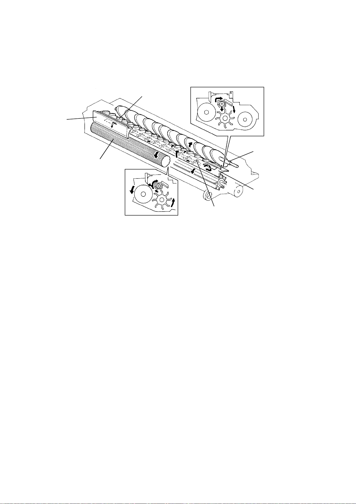
6.5 TONER SUPPLY AND AGITATOR DRIVE MECHANISM
[A]
[D]
[C]
[B]
[A]
[D]
[E]
[J]
[H]
[F]
[I]
[G]
The toner supply clutch gear [A] turns when the main motor [B] is on. The
transmission of this rotation to the toner supply drive gear [C] is controlled by
the toner supply clutch [D].
When the toner supply clutch energizes, the toner supply drive gear starts
turning and drives the toner supply roller gear [E]. Toner catches in the
grooves on the toner supply roller [F]. Then, as the grooves turn past the pin
hole plate [G], the toner drops into the development unit through the pin holes.
The toner agitator [H] mechanism, which is contained in the toner cartridge,
prevents toner from clumping. The toner agitator gear [I] turns whenever the
toner supply clutch energizes. Rotation passes through the toner cartridge
casing to the agitator junction [J].
FT3013/3213 2-36 STM
Page 62

6.6 TONER SUPPLY AMOUNT
This copier has two different ways of controlling the amount of toner supplied.
Normally, the detect supply mode controls toner supply; however, a fixed
supply mode also can be selected by SP30.
6.6.1 Detect Supply Mode (SP30 = 0)
The amount of toner supplied depends on the ID sensor data and the detect
toner supply ratio data. The toner supply clutch on time in each copy cycle is
calculated as follows:
Toner Supply Clutch ON Time = I x T (pulses)
Where : I = ID Sensor Data
T = Detect Toner Supply Ratio Data (SP31)
ID Sensor Data
Vsp/Vsg x 100
(Vsp, if Vsg = 4.0 volts)
0 to 10.3%
(0 to 0.41 volts)
10.3 to 10.8%
(0.41 to 0.43 volts)
10.8 to 11.8%
(0.43 to 0.47 volts)
11.8 to 15.2%
(0.47 to 0.61 volts)
15.2 to 62.5%
(0.61 to 2.5 volts)
(See note below.)
62.5 to more than 100%
(2.5 to 5.0 volts)
Toner supply level
(Toner supply ratio, SP31 = 0)
No toner supply
(0%)
1
(3.75%)
2
(7.5%)
3
(15%)
4
(30%)
Fixed supply mode
ID sensor data
0
22
44
87
174
(Toner End level)
N/A
(Abnormal Condition)
NOTE: If this condition is detected two times consecutively, the toner
supply ratio rises to 60% (ID Sensor Data = 348), which is double
that at toner supply level 4.
STM 2-37 FT3013/3213
Page 63

Detect Toner Supply Ratio Data (SP31)
Data (SP31) Toner supply ratio at toner supply level 3 Toner supply ratio data
0 15% 2
1 7% 1
2 30% 4
3 60% 8
For example: Vsp = 0.45 volts, which means the toner
supply level is "2" and the ID sensor data is 44.
The data of SP31 is set to "0".
The toner supply ratio is 15% and the toner
supply data is 2.
Toner Supply Clutch ON Time
= I x T
= 44 x 2
= 88 (pulses)
= 352 (msec.) (1 pulse = 4.0 msec.)
FT3013/3213 2-38 STM
Page 64

6.6.2 Fixed Supply Mode (SP30 = 1)
The amount of toner supplied depends on the fixed toner supply ratio data
and the paper size data. The toner supply clutch on time in each copy cycle
is calculated as follows:
Toner Supply Clutch ON Time = T x P x 2 (pulses)
Where: T = Fixed Toner Supply Ratio Data (SP32)
P = Paper Size Data
Fixed Toner Supply Ratio Data (SP32)
Data (SP32) Toner supply ratio Toner supply ratio data
0 7.0% 2
1 3.5% 1
2 10.5% 3
3 14.0% 4
Paper Size Data
Paper size Paper size data
B4 43
A4R 29
B5R 23
A5R 15
10" x 14", 81/2" x 14", 81/4" x 14" 43
81/2" x 13", 81/4" x 13" (F4), 8" x 13" 33
81/2" x 11", 8" x 101/2" 29
8" x 10" 27
51/2" x 81/2" 14
For example: The data of SP32 is set to "0".
The toner supply ratio is 7.0% and the toner
supply data is 2.
Paper size is 8.5" x 11". The paper size data is 29.
Toner Supply Clutch ON Time
= T x P x 2
= 2 x 29 x 2
=116 (pulses)
= 464 (msec.) (1 pulse = 4.0 msec.)
STM 2-39 FT3013/3213
Page 65

6.7 TONER END CONDITION
The image density sensor is used to detect a toner end condition in both
detect and fixed supply modes.
6.7.1 Near Toner End Condition
When the Vsp/Vsg x100 becomes greater than 15.2, the toner density
detection cycle changes from every 10 copies to 5 copies. When this
condition is detected again, the toner supply ratio becomes two times the
amount of toner supply level 4 (Toner supply ratio = 60%, ID sensor data =
348). Then, when this condition is detected five times consecutively, the CPU
determines that there is a near toner end condition and starts blinking the
Add Toner indicator.
6.7.2 Toner End Condition
After the Add Toner indicator starts blinking (Near Toner End Condition), the
operator can make 50 copies. If a new toner cartridge is not added within that
50 copy interval, copying is inhibited and a toner end condition is determined.
In this condition, the Add Toner indicator lights and the Start indicator turns
red.
Example: (Detect Mode)
Copy number
1st∼5th copies 1st copy 15.3 30%
6th∼10th copies 6th copy 15.3 60%
11th∼15th copies 11th copy 15.3 60%
16st∼20th copies 16th copy 15.3 60%
21st∼25th copies 21st copy 15.3 60%
•
•
•
•
71st copy ---- ---- ----
Toner density
detection cycle
•
•
•
•
Vsp/Vsg
x 100
•
•
•
•
Toner supply
(If SP31=0)
ratio
•
•
•
•
Indicator
Add Toner indicator starts
blinking.
(Near toner end condition)
Add Toner indicator blinks.
(Near toner end condition)
Add Toner indicator lights.
(Toner end condition)
FT3013/3213 2-40 STM
Page 66

When the Vsp/Vsg x 100 becomes greater than 28.0 for two consecutive
toner detection cycles, the CPU determines immediately that there is a toner
end condition and copying is inhibited. This causes the Add Toner indicator
to light and the Start indicator turns red.
Example: (Detect Mode)
Copy number
1st∼5th copies 1st copy 18.3 30%
6th∼10th copies 6th copy 28.3 60%
11th copy 11th copy 28.3 ----
Toner density
detection cycle
Vsp/Vsg
x 100
Toner supply
ratio
(If SP31=0)
Indicator
Add Toner indicator lights.
(Toner end condition)
6.7.3 Toner End Recovery
After the toner cartridge is replaced and the front cover is closed, the CPU
turns on the main motor, and turns on the toner supply clutch to supply toner
to the development unit from the toner cartridge. Toner density is detected
(Vsp and Vsg are monitored) during this period. When Vsp/Vsg x 100
becomes less than 15.2, the main motor is turned off and the toner end or
near end condition is cleared.
If Vsp/Vsg x 100 stays greater than 15.2 (when the toner cartridge is not
replaced), the toner end or near end condition is not cleared. If Vsp/Vsg x100
stays between 15.2 to 28.0, only one copy can be made. After the copy job
the Add Toner indicator lights and copying is inhibited. If Vsp/Vsg x100 stays
greater than 28.0, copying is inhibited. This prevents the customer from
making copies with the toner end condition by opening and closing the front
cover.
STM 2-41 FT3013/3213
Page 67

7. IMAGE TRANSFER & PAPER SEPARATION
[D]
[C]
[B] [A]
7.1 IMAGE TRANSFER
A high negative voltage (--5.0 kilovolts) is applied to the transfer corona wire
[A], and the corona wire generates negative ions. These negative ions are
applied to the back side of the copy paper. This negative charge forces the
paper against the drum and attracts the positively charged toner onto the
paper.
7.2 PAPER SEPARATION
After image transfer the copy paper must be separated from the drum. In
order to break the attraction between the paper and the drum, the separation
corona wire [B] applies an ac charge to the reverse side of the paper. The
stiffness and weight of the paper then causes it to separate from the drum.
The negative charge on the paper (from the transfer corona) is not
completely discharged until the paper is far enough from the drum that the
toner will not be reattracted to the drum. The pick-off pawl [C] ensures that
thin, low stiffness paper and upward curled paper separate completely. The
spurs [D] prevent the unfused toner on the paper from being smeared by the
pick-off pawl.
FT3013/3213 2-42 STM
Page 68

7.3 TRANSFER/SEPARATION CORONA CIRCUIT
CN1-1
CN1-2
CN1-3
CN1-4
Power Pack
- TC/SC
(P2)
Transfer
Control
Separation
Corona
SC [ 24]
TC [ 24]
Main Board
(PCB1)
VA [24]
GND [0]
CN117-15
CN117-14
CN117-13
CN117-12
To apply the negative charge for the transfer corona, the main board outputs
a LOW signal (CN117-13) shortly after the Start key is pressed.
To apply an ac charge for the separation corona, the main board also outputs
a LOW signal (CN117-14) at about the same time.
The TC/SC power pack has a dc to dc converter and a dc to ac inverter. The
dc to dc converter changes +24 volts to --5.0 kilovolts for the transfer corona.
The inverter changes +24 volts to the 3.8 kilovolts ac (500 Hz) for the
separation corona.
The separation corona circuit in the TC/SC power pack has a current leak
detection circuit for safety. When this circuit detects that more than 3.0
milli-amperes is being supplied to the separation corona, the separation
corona turns off immediately. When the main switch is turned off and on, or
the front cover or the exit cover is opened and closed, this condition is
cleared.
STM 2-43 FT3013/3213
Page 69

8. DRUM CLEANING
8.1 OVERVIEW
[D]
[A]
[C]
Rev. 1/95
[B]
This copier uses the counter blade system for drum cleaning.
The cleaning blade [A] is angled against drum rotation. This counter blade
system has the following advantages:
• Less wearing of the cleaning blade edge.
• High cleaning efficiency.
Due to the high efficiency of this counter blade system, this copier does not
use a cleaning brush.
The removed toner falls into the cleaning unit. The toner collection roller [C]
carries the used toner to the used toner tank. The quenching lamp [D], which
consists of four small neon lamps, neutralizes any charge remaining on the
drum in preparation for the next copy cycle.
The cleaning blade is always in contact with the drum. It releases when the
release knob is pressed. This prevents the drum from being damaged when
the cleaning unit is removed or installed.
FT3013/3213 2-44 STM
Page 70

8.2 DRIVE MECHANISM
[G]
[E]
[D]
[C]
[B]
[A]
The rotation of the main motor [A] is transmitted to the cleaning unit through
the main motor gear [B], the relay gears [C], and the cleaning drive gear [D].
The gear [E] driven by the cleaning drive gear passes the rotation to the toner
collection roller gear [F].
The cleaning blade [G] is mounted in the center of the blade and is tilted to
apply even pressure.
[F]
STM 2-45 FT3013/3213
Page 71

8.3 USED TONER OVERFLOW DETECTION
The CPU uses the toner end counter and an overflow counter to detect the
used toner overflow.
A used toner overflow condition is detected when either of the following
conditions occur.
(1) When the overflow counter reaches 80K copies.
The overflow counter counts the total number of copies since the last time the
toner end counter was cleared. When the overflow counter reaches 80K
copies, the CPU starts to blink "E70" on the operation panel. An additional
250 copies can be made before the Start indicator turns red and copying is
inhibited.
(2) When the number of toner end counter reaches 9.
When the number of the toner end counter reaches 9, the following number
of copies can be made before the "E70" starts to blink.
This number is determined by the number in the overflow counter when the
9th toner end condition was detected.
N: Overflow Counter
78K < N < 80K
The remaining copies to reach
80K copies can be made.
75K < N ≤ 78K 2K copies can be made
50K < N ≤ 75K 3K copies can be made
40K < N ≤ 50K 1K copies can be made
less than 40K No copy
After the above number of copies is made, the CPU starts to blink "E70". Up
to an additional 250 copies can be made after this. Then, the Start key turns
red and copying is inhibited.
After disposing of the toner in the used toner tank, use SP83 to clear the
toner end counter and overflow counter.
Toner end counter clear (SP83)
Data (SP83) Memory counter
0 Not clear
1 Clear
SP58 shows the number in the toner end counter. When "1" is input in SP83,
the data of SP58 is cleared. There is no SP mode to display the overflow
counter.
FT3013/3213 2-46 STM
Page 72

9. PAPER FEED AND REGISTRATION
9.1 OVERVIEW
[F]
[A]
[E]
[E]
[B]
This copier has one paper feed station and a by-pass feed table [A].
The paper feed station uses a paper tray [B] which can hold 250 sheets. The
by-pass feed table can hold only 1 sheet.
The paper tray uses a semicircular feed roller [C] and corner separator [D]
system. The semicircular feed rollers (six rollers) make one rotation to drive
the top sheet of paper to the relay rollers [E], which then feed the paper to the
registration rollers [F].
The paper tray has two corner separators, which allow only one sheet to
feed. They also serve to hold the paper stack.
When the paper tray is closed after the paper is loaded, the paper tray
pushes the tray set switch. This informs the CPU that the paper tray is set.
An auto start system is used for the by-pass feed table. When copy paper is
inserted into the by-pass table, paper will be fed into the copier automatically
without having to press the Start key.
[C]
[D]
This machine has no sensors or switches to detect the paper size.
STM 2-47 FT3013/3213
Page 73

9.2 PAPER LIFT MECHANISM
[A]
[F]
[E]
[D]
[C]
[B]
When the paper tray [A] is closed after paper is loaded, the plate release
slider [B], which is mounted on the bottom part of the paper tray, is pushed by
the projection [C] of the copier frame and the release slider disengages the
bottom plate hook [D]
Once the bottom plate hook is disengaged, the bottom plate is raised by the
pressure springs [E] and the paper stack is pushed up to the corner
separators [F]. This keeps the stack of paper at the correct height.
FT3013/3213 2-48 STM
Page 74

9.3 PAPER LENGTH DETECTION (Paper Feed Station)
The paper length is measured using the registration sensor and the
determined paper size is stored in memory. The paper length measurement
is performed only during the first copy after the following conditions:
1. When the main switch is turned on.
2. When the front cover is opened and closed.
3. When the paper tray is opened and closed.
The previous paper length is also cleared from memory by the above actions.
As shown in the following table, the CPU determines the size of the paper in
the paper tray based on the period of time (paper length) it takes for the
paper to pass the registration sensor.
Paper length (mm) Paper size
364 B4
356 10" x 14"
330 81/2" x 13"
297 A4R
279 81/2" x 11"
267 8" x 101/2"
257 B5R
254 8" x 10"
216 51/2" x 81/2"
210 A5R
Since the CPU does not have the paper length in memory for the first copy
cycle, the CPU controls the machine for the maximum paper size of B4 (257
mm x 364 mm).
From the second copy cycle on, the CPU controls the machine for the correct
paper size based on the data stored during the first paper cycle.
Whenever the by-pass feed table is used, the CPU determines the paper size
to be B4 (257 mm x 364 mm).
STM 2-49 FT3013/3213
Page 75

9.4 PAPER FEED DRIVE MECHANISM
[G]
[D]
[C]
[A]
[F]
[I]
[H]
[B]
[J]
[G]
[D]
Through a series of gears and a timing belt, main motor rotation is
transmitted to the relay gear [A], paper feed clutch gear [B] and then the relay
roller clutch gear [C].
-- Feed rollers --
The paper feed clutch gear is secured on the shaft of the semicircular feed
rollers [D]. The CPU energizes the paper feed clutch [E] after the Start key is
pressed. At this time the semicircular feed rollers start rotating to feed the
paper. The paper feed clutch stays on for 620 milliseconds to rotate the
semicircular feed rollers for only one revolution. The leading edge of the copy
paper reaches to the 1st relay rollers [F] when the paper feed clutch
de-energizes.
[E]
[F]
-- 1st and 2nd relay rollers --
The relay roller clutch gear is secured on the shaft of the 2nd relay rollers [G].
The rotation timing for the 2nd relay rollers and the 1st relay rollers is
controlled by the relay roller clutch [H]. The CPU energizes the relay roller
clutch after the Start key is pressed (The same timing with the paper feed
clutch). At this time, both the 1st and 2nd relay rollers start rotating. The drive
is transmitted to the 1st relay rollers through a relay gear [I]. Paper is fed from
the 1st and 2nd relay rollers to the registration rollers [J].
FT3013/3213 2-50 STM
Page 76

9.5 BY-PASS FEED TABLE (By-pass Auto Feed Mechanism)
[B]
[C]
[A]
[D]
[E]
The by-pass feed table [A] can load only one sheet of paper.
When a sheet of copy paper is set in the by-pass feed table, the leading edge
of the copy paper activates the relay sensor [B] which sends a low signal to
the main board. The CPU energizes the relay roller clutch [C] after 500
milliseconds to feed the copy paper. Then, copy paper is fed from the 2nd
relay rollers [D] to the registration rollers [E].
[B]
[A]
STM 2-51 FT3013/3213
Page 77

9.6 PAPER REGISTRATION
[C]
[F]
[D]
[E]
[B]
[A]
[G]
[F]
[I]
[H]
Main motor rotation is transmitted to the timing belt [A] through a series of
gears. The timing belt rotates the relay gear [B] and then the registration
roller clutch gear [C]. When the registration clutch [D] is energized, the
rotation of the clutch gear is transmitted to the lower registration roller [E].
The registration sensor [F], which is positioned just before the registration
rollers [G], control the relay roller clutch stop timing. The relay roller clutch
stays on for 180 milliseconds after the leading edge of the paper actuates the
registration sensor. The CPU then turns off the relay roller clutch. This delay
allows time for the paper to press against the nip of the registration rollers
and causes the paper to buckle slightly so as to correct any paper skew.
The CPU energizes the registration clutch and re-energizes the relay roller
clutch at the proper time to align the paper with the image on the drum. The
registration, 1st [H] and 2nd [I] relay rollers feed the paper to the image
transfer section.
The registration sensor is also used for paper misfeed detection.
FT3013/3213 2-52 STM
Page 78

9.7 PAPER FEED AND MISFEED DETECTION TIMING
1st Copy = B4
2nd Copy = A4/81/2 "x 11"
The relay sensor, registration sensor and exit sensor are used for misfeed
detection. If the CPU detects a misfeed, the Check Paper Path and the
Misfeed Location Number (PE, J1, J2) indicators turn on.
When the main switch is turned on, the CPU checks these three sensors for
initial misfeed.
During the copy cycle, the CPU performs three types of misfeed detection:
PE: Checks whether the relay sensor is actuated within 3.5 seconds after the
Start key is pressed (only PE indicator turns on). This machine has no
indicator or sensor to detect the paper end. The PE indicator is lit in the
paper end condition as well.
J1: Checks whether the registration sensor is actuated within 4.4 seconds
after the Start key is pressed. (J1 and Check Paper Path indicators turn
on.)
J2: Checks whether the exit sensor is actuated within 7.4 seconds after the
Start key is pressed, or whether the copy paper has passed through the
exit sensor 4.24 seconds (B4 size) after the exit sensor has been
actuated (3.57 seconds for A4/LT lengthwise).
(J2 and Check Paper Path indicators turn on.)
STM 2-53 FT3013/3213
Page 79
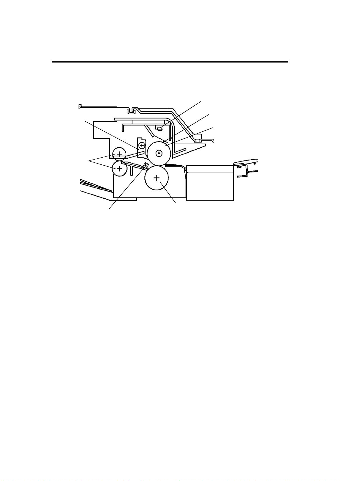
10.IMAGE FUSING
10.1 OVERVIEW
[D]
[E]
[F]
[B]
[G]
After the image is transferred, the copy paper enters the fusing unit.
The image is fused to the copy paper by the process of heat and pressure
through the use of a hot roller [A] and pressure roller [B].
The CPU monitors the hot roller’s surface temperature through a thermistor
[C] which is in contact with the hot roller’s surface. A thermoswitch [D]
protects the fusing unit from overheating.
[C]
[A]
The hot roller strippers [E] separate the copy paper from the hot roller and
direct it to the exit rollers [F]. The exit sensor [G] monitors the movement of
the copy paper through the fusing unit and acts as a misfeed detector. The
exit rollers drive the copy paper to the copy tray.
FT3013/3213 2-54 STM
Page 80

10.2 FUSING DRIVE MECHANISM AND COVER SAFETY
SWITCH
[H]
[I]
[C]
[D]
[D]
[A]
When the upper unit is closed the fusing engagement lever [A] is pressed
down and an idler gear [B] engages with the hot roller gear [C]. Rotation
passes from the hot roller gear through the idler gears [D] to the exit roller
gear [E].
The fusing unit drive release mechanism automatically disengages fusing
drive when the upper unit is opened. This allows the fusing rollers to rotate
freely so that misfed paper can be easily removed.
[B]
[F]
[E]
[G]
[H]
[A]
[E]
[C]
[B]
When the exit cover and/or the front cover is opened, the switch lever [F]
and/or the switch arm [G] release the cover safety switch [H] to remove all
power from the copier.
The exit sensor [I] is used for paper misfeed detection.
STM 2-55 FT3013/3213
Page 81

10.3 FUSING LAMP CONTROL CIRCUIT
CN107-1
B
Zero
Cross
CPU
Main Board (PCB1)
TP102
(HET)
R112
+5V
I/O
IC114
IC104
R110
6
R109 R111
+24V
8
5
24V
0V
+5V
+24V
7
4
Trigger Pulse
C106
R107
R108
C
CN118-2, 3
Q101
CN118-1, 4
CN114-8
CN114-4
CN114-6
CN114-7
Fusing
Thermistor
CN401-1
CN401-5
CN401-3
CN401-2
AC Drive Board (PCB2)
R412
PC402
TRC402
R414
RA401
Power Relay
CR402
RA401
T402
T405
Thermoswitch
Fusing
Lamp
D
T406
A
AC115V
AC220V
AC240V
T407
The main board monitors the fusing temperature through a thermistor. It also
uses the zero cross signal generated by the dc power supply board to
accurately control the applied power.
Normally, the voltage applied to the lamp is a full ac waveform. However,
through SP29, fusing power can be phase controlled. (Normally, phase
control is used only if the customer has a problem with electrical noise or
interference.)
When the main switch is turned on, the main board starts to output a trigger
pulse (C), which has the same timing as the zero cross signal (B), to the ac
drive board. This trigger pulse allows maximum ac power to be applied to the
fusing lamp. When the operating temperature is reached, the CPU stops
outputting the trigger pulse (trigger goes HIGH) and the fusing lamp turns off.
FT3013/3213 2-56 STM
Page 82

10.3.1 Phase Control Mode
AC Power
A
Zero Cross
Trigger Low Temp
Fusing Lamp Power
Trigger High Temp
Fusing Lamp Power
B
C1
D1
C2
D2
The main board sends the fusing lamp trigger pulse (LOW active) (C) to the
ac drive board. PC402 activates TRC402, which provides ac power to the
fusing lamp at the trailing edge of each trigger pulse. The trigger pulse goes
HIGH when the main board receives the zero cross signal.
The amount of time that power is applied to the fusing lamp (D) depends on
the temperature of the hot roller.
The trigger pulse (LOW part) is wider (C1) when the hot roller temperature is
lower, and it is narrower (C2) when the hot roller is near the operating
temperature.
10.3.2 Overheat Protection
IC104 and Q101 form an overheat protection circuit. When the fusing lamp is
controlled within the normal range, pin 7 of IC104 stays LOW; therefore,
Q101 stays on, allowing PC402 to operate. If the hot roller temperature
reaches 240°C, the resistance of the thermistor becomes too low. At that
time, pin 7 of IC104 becomes HIGH, turning off Q101 and stopping PC402.
At the same time "E53" lights on the operation panel and the power relay
(RA401) turns off.
Even if the thermistor overheat protection fails, a thermoswitch is installed in
series with the fusing lamp that will prevent the fusing unit from excessively
overheating. If the thermoswitch temperature reaches 170°C, the
thermoswitch opens, removing power from the fusing lamp.
STM 2-57 FT3013/3213
Page 83

10.4 FUSING LAMP CONTROL
Temp
198°C
195°C
170°C
150°C
Fusing Lamp
Exposure Lamp
ON
OFF
ON
OFF
Ready Start key
pressed
Start key
pressed
Time
When the main switch is turned on, the CPU starts sending a trigger pulse to
turn on the fusing lamp.
When the fusing temperature reaches 150°C, the Start indicator turns green
(ready temperature). When the fusing temperature reaches 170°C (stand-by
temperature), the CPU stops sending the trigger pulse and the fusing lamp
turns off. The fusing lamp is turned on and off to keep the hot roller surface at
the stand-by temperature of 170°C.
When the Start key is pressed, the fusing lamp is turned on to heat the hot
roller up to the operation temperature of 195°C. (The operation temperature
can be changed by setting the maximum temperature in SP79.)
To prevent any copy image problems caused by the exposure lamp intensity
fluctuation, the fusing lamp (900W) does not turn on while the exposure lamp
is on, even if the fusing temperature drops below 195°C.
FT3013/3213 2-58 STM
Page 84

10.5 ENERGY SAVER FUNCTION
When the copier is not in use, the energy saver function reduces the power
consumption by decreasing the fusing temperature. The energy Saver
indicator turns on and all the other indicators turn off.
For this copier, the energy saver function cannot be entered manually. To
access this function, SP78 (Auto Energy Saver Mode) must be set to "1". And
since this function is applied at the time when the machine enters the auto
reset, SP15 (Auto Reset Time) must be set to "0" or "1" as well.
The energy saving ratio can be selected by SP86 as shown in the following
table.
SP data (SP86)
0 approx. ∆56% approx. 60°C approx. 25 sec.
1 approx. ∆47% approx. 90°C approx. 19 sec.
2 approx. ∆37% approx. 120°C approx. 12 sec.
3 approx. ∆25% approx. 150°C approx. 5 sec.
Target benefit of
power saving
Fusing temperature Warm-up time
NOTE: The energy saving ratio in the above table are standard values
measured in laboratory tests under controlled conditions. The actual
ratios will vary depending on environmental conditions, copy modes,
power supply conditions, and measurement instruments.
The greater the energy saving ratio is, the longer the wait time until the copier
returns to the ready condition.
The copier exits the energy saver mode upon the following actions.
1. Pressing any key except the Start key.
2. Setting copy paper on the by-pass feed table.
3. Opening the optional DF or setting an original on it. (FT3213 only)
4. Opening and closing the front cover.
5. Turning the main switch OFF/ON.
STM 2-59 FT3013/3213
Page 85

Page 86

SECTION 3
DOCUMENT FEEDER
Page 87

Page 88

1. SPECIFICATIONS
Original Size: Maximum: A3 or 11" x 17"
Minimum: A5 Lengthwise or 51/2" x 81/2"
Original Weight: 53 to 105 g/m2 (14 to 28 lb)
Original Feed: Automatic Feed - ADF mode
Original Tray Capacity: 30 sheets - 80 g/m2 (20 lb)
Original Set: Face up - First sheet on top
Original Transport: One flat belt
Copying Speed: 13 copies/minute
(A4 lengthwise or 81/2" x 11" lengthwise)
Power Consumption: 35 W
Dimensions (W x D x H): 590 x 443 x 100 mm (23.3" x 17.5" x 4.0")
Weight: Approximately 7 kg (15.5 lb)
• Specifications are subject to change without notice.
• The document feeder (DF40) can only be installed on the
FT3213
• Only DF40 document feeders from S/N A296-4-05-0001 have
the necessary accessory parts for installation on to the
FT3213. These accessory parts include (1) ADF Interface
Bracket Assy. P/N A3650661 & (2) Shoulder screws
P/N A0771361.
FT3013/3213 3-1 STM
Page 89

2. COMPONENT LAYOUT
2.1 MECHANICAL COMPONENTS
1
2 3 4 65
8
910
7
1. Pulse Generator Disk
2. Friction Belt
3. Pick-up Lever
4. Pick-up Roller
5. Original Table
6. Exit Roller
7. Transport Belt
8. Transport Belt Roller
9. Feed Roller
10. Relay Roller
2.2 ELECTRICAL COMPONENTS
4 5
3
2
1
6
7 8
9
10
12
11
1. Pick-up Solenoid
2. Registration Sensor
3. Original Set Sensor
4. Feed Clutch
5. Pulse Generator Sensor
6. DF Motor
STM 3-2 FT3013/3213
7. Insert Original Indicator
8. Original Misfeed Indicator
9. Lift Switch
10. DF Main Board
11. DF Transformer
12. DF Interface Board
Page 90

3. ELECTRICAL COMPONENT DESCRIPTIONS
SYMBOL NAME FUNCTION LOCATION
Motor
M1 DF Drives all the document feeder components. 6
Solenoid
SOL1 Pick-up Solenoid Energizes to press the pick-up lever against
the stack of originals in preparation for
original feed-in.
Clutch
CL1 Feed Clutch Turns on to transmit main motor rotation to
the feed roller.
Switch
SW1 Lift Switch Informs the CPU when the DF is lifted and
also serves as the misfeed reset switch for
the DF.
Sensors
S1 Pulse Generator
Sensor
S2 Original Set
Sensor
S3 Registration
Sensor
Printed Circuit Board
PCB1 DF Main Board Controls all DF functions. 10
PCB2 DF Interface
Board
Transformer
TR1 DF Transformer Steps down the wall voltage to 25 volts ac. 11
LEDs
LED1 Original Misfeed
Indicator
LED2 Insert Original
Indicator
Supplies timing pulse to the DF main board. 5
Informs the copier CPU that originals have
been placed and causes the Insert Original
indicator to go out.
Sets original stop timing and checks for
original misfeeds.
Interfaces between the copier main board
and the DF.
Turns on when an original is misfed. 8
Turns off when the originals are inserted into
the original table.
1
4
9
3
2
12
7
FT3013/3213 3-3 STM
Page 91

4. POWER DISTRIBUTION
+24 V (VA)
Regulator
+5 V (VC)
Rectifier
AC Drive Board
(PCB2)
115 Vac
220--230 Vac
240 Vac
DF
Transformer
(TR1)
25 Vac
Smoothing
Rectifier
DF Main Board (PCB1)
The document feeder uses two dc power levels: +24 volts, and +5 volts.
When the main switch is turned on, the DF transformer receives the wall
outlet ac power through the ac drive board and outputs 25 volts ac to the DF
main board. Then, the dc power supply circuit on the DF main board converts
the 25 volts ac input to +24 volts and +5 volts.
The +24 volts is used by the DF motor, the pick-up solenoid, and the feed clutch.
The +5 volts is used by other electrical components.
STM 3-4 FT3013/3213
Page 92

5. BASIC OPERATION
When the main switch is turned on, the DF CPU sends the "DF installed"
signal to the copier CPU. Receiving this signal, the copier CPU recognizes
that the document feeder is installed and sends the "DF confirmed" signal to
the DF CPU.
When originals are placed on the original table, the Insert Original indicator
turns off and the DF CPU sends the "original set" signal to the copier CPU to
inform it that the originals have been set.
When the Start key is pressed, the copier CPU sends the "feed-in" signal to
the document feeder. On receipt of this signal, the DF CPU energizes the DF
motor, the pick-up solenoid, and the feed clutch to feed in the bottom sheet of
the original stack onto the exposure glass. The pick-up solenoid, and the
feed clutch remain energized until the original’s leading edge reaches the
registration sensor. The DF motor turns off shortly after the original’s trailing
edge passes the registration sensor. Then, the DF motor pauses and
reverses for a moment to align the edge of the original with the scale.
The scanner starts, and the start timing does not depend on the progress of
the original through the DF. When the scanner reaches the return position,
the copier CPU sends the "original change" signal to the DF CPU in order to
exchange the current original with the next original.
FT3013/3213 3-5 STM
Page 93

6. INTERFACE CIRCUIT
Copier Main Board (PCB1) DF Interface Board (PCB4)
CPU
TXD
RXD
+5V
CN120-2
CN120-5
CN120-4
CN120-1
CN2-1
CN2-4
CN2-2
CN2-3
Fiber Optics
CN1 CN118
Fiber Optics
DF Main Board (PCB1)
RXD
CPU
TXD
The copier CPU and the DF CPU communicate via the interface board using
fiber optics. The interface board changes the optical signals to electrical
signals (and vice versa).
STM 3-6 FT3013/3213
Page 94

7. ORIGINAL FEED
7.1 ORIGINAL PICK-UP MECHANISM
[C]
[B]
[A]
[D]
After setting the originals on the original table, the originals contact the feeler
[A] of the original set sensor and cause the feeler to move out of the sensor.
The DF CPU then sends the original set signal to the copier CPU to inform it
that the document feeder will be used. When the Start key is pressed, the
pick-up solenoid [B] is energized. The original stack is then pressed between
the pick-up lever [C] and pick-up roller [D]. The rotation of the pick-up roller
advances the bottom original.
FT3013/3213 3-7 STM
Page 95

7.2 ORIGINAL SEPARATION MECHANISM
[C]
[E]
[B]
[D]
[C]
[A]
[B]
[D]
[A]
The feed roller [A] and the friction belt [B] are used to feed in and separate
the originals [C]. Only the bottom original is fed because the friction belt
prevents any other originals from feeding.
Original feed starts when the pick-up lever [D] presses the original stack and
the rotation of the pick-up roller [E] advances the bottom original of the stack.
The feed roller moves the original past the friction belt because the driving
force of the feed roller is greater than the resistance of the friction belt. The
friction belt prevents multiple feeds because the resistance of the friction belt
is greater than the friction between original sheets.
STM 3-8 FT3013/3213
[E]
Page 96

7.3 ORIGINAL FEED-IN MECHANISM
[E]
[A]
The DF motor [A] drives the feed roller [B], the pick-up roller [C], the relay
rollers [D], and the transport belt roller [E] via timing belts and a gear train.
The feed roller and the pick-up roller are controlled by the feed clutch [F], but
the relay rollers and the transport roller are directly driven by the DF motor.
The idler rollers [G] on the feed roller shaft are free from the shaft.
[C]
[F]
[G]
[D]
[B]
When the Start key is pressed, the DF motor is energized and the relay
rollers and transport belt roller start turning. 100 milliseconds after the DF
motor starts turning, the pick-up solenoid and the feed clutch is energized.
The pick-up and feed rollers then start turning and carry the original between
the relay rollers and the idler rollers. The pick-up solenoid and the feed clutch
are de-energized when the original’s leading edge passes through the
registration sensor.
The DF motor remains energized to deliver the original to the exposure glass
until a certain number of pulses (10 to 25 pulses) after the original’s trailing
edge passes through the registration sensor. Then, the DF motor pauses and
reverses for 15 pulses to align the edge of the original with the scale.
To feed the second original, the DF motor starts rotating when the scanner
reaches the return position. (The copier CPU sends the original change
signal to the DF CPU.) At this time, the transport belt starts carrying the first
original on the exposure glass to the exit roller. The timing for when the
pick-up solenoid and the feed clutch are energized for the second original
depends on the length of the first original detected by the registration sensor.
FT3013/3213 3-9 STM
Page 97

7.4 ORIGINAL FEED-OUT MECHANISM
[D]
[A] [B]
The exit rollers are driven by the DF motor through a gear train, the transport
belt roller, the transport belt [A], the transport belt idler roller [B], and the exit
roller drive belt [C]. When the DF CPU receives the original change signal
from the copier CPU, the DF motor starts turning. Simultaneously, the
transport belt carries the original to the exit rollers [D] and the exit rollers take
over the original feed-out.
[C]
STM 3-10 FT3013/3213
Page 98

7.5 DF MOTOR CIRCUIT
DF Main Board (PCB1)
Original
Change
Signal
R x D
CPU
Forward
Reverse
ON/OFF
GATE
IC
Forward
Reverse
+24 V (VA)
DRIVER
IC
+5 V (VC)
CN117-1
CN117-2
Forward: +24 V
Reverse: 0 V
Forward: 0 V
Reverse: +24 V
DF Motor
(M1)
Timing Pulse
Pulse
Generator
Sensor
(S1)
A 24 volt dc motor is used as the DF motor. When the CPU receives the feed
signal from the copier, the CPU outputs the ON signal and the Forward signal
to the gate IC. On receipt of the forward signal from the gate IC, the driver IC
outputs 24 volts to CN117-1 and 0 volts to CN117-2. This causes the DF
motor to start turning in the forward direction.
Within 10 to 25 pulses after the original’s trailing edge passes through the
registration sensor, the CPU stops sending the ON signal and the Forward
signal. The DF motor stops turning. Then the CPU outputs the ON signal and
the reverse signal for 15 pulses. Then the driver IC outputs 0 volts to
CN117-1 and +24 volts to CN117-2 to reverse the DF motor.
FT3013/3213 3-11 STM
Page 99

7.6 ORIGINAL FEED AND MISFEED DETECTION TIMING
Feed Signal (Start key) Original Change Signal
0 500 1000 0 500 1000
Timing (ms)
10 to 25 pulses
10 to 25 pulses
DF Motor
Pick-up Sol.
and
Feed Clutch
Registration
Sensor
100 ms
500 ms
15 pulses
J0
1,500 ms
❋
: The timing depends on the length of the first original.
J0
❋
15 pulses
J0
500 ms
1,500 ms
The above chart shows the original feed timing for the original size of A4 or
8.5" x 11" lengthwise and the detection timing.
The registration sensor is used for a misfeed detection. If the DF CPU
detects that a misfeed exists, the DF CPU lights the Original Misfeed
indicator and sends the original misfeed signal to the copier CPU. Then the
copier CPU lights the check paper path and the Misfeed Location Number
(JO) on the operation panel. When the main switch is turned on, the DF CPU
checks the registration sensor output for the initial original misfeed. During
the original feed-in, the DF CPU performs two kinds of original misfeed
detections:
1. Whether the registration sensor is actuated within 500 milliseconds after
the pick-up solenoid and the feed clutch turn on.
2. Whether the original has passed through the registration sensor 1,500
milliseconds after the registration sensor has been actuated.
STM 3-12 FT3013/3213
Page 100

 Loading...