

Page 1

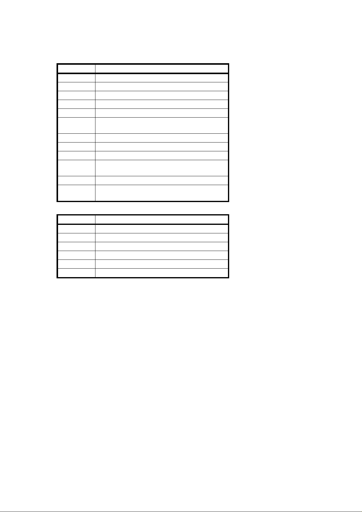
FACTORY SETTING P/N A0771391C
SP NUMBER FACTORY SETTING DATA
41 0 1 2 3 4 5 6 7 8 9 10 11 12 13 14 15
42 0 1 2 3 4 5 6 7 8 9 10 11 12 13 14 15
43 0 1 2 3 4 5 6 7 8 9 10 11 12 13 14 15
44
47
48 120 121 122 123 124 125 126 127 128
129 130 131 132 133 134 [ ]
60 0 1 2 3 4 5 6 7 8
62 0 1 2 3 4 5 6 7 8
SERIAL NO.
Page 2

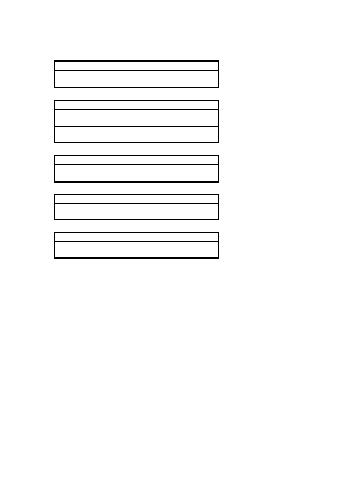
FACTORY SETTING P/N A0771390C
SP NUMBER FACTORY SETTING DATA
41 0 1 2 3 4 5 6 7 8 9 10 11 12 13 14 15
42 0 1 2 3 4 5 6 7 8 9 10 11 12 13 14 15
43 0 1 2 3 4 5 6 7 8 9 10 11 12 13 14 15
44
47
48 120 121 122 123 124 125 126 127 128
129 130 131 132 133 134 [ ]
60 0 1 2 3 4 5 6 7 8
62 0 1 2 3 4 5 6 7 8
SERIAL NO.
Page 3
TEST POINTS
Copier Main Board
NUMBER FUNCTION
TP101 GND
TP102 HET (Fusing Thermistor)
TP103 GND
TP104 GIN (Grid Voltage Feed Back)
TP105 BIN (Development Bias Feed Back)
TP106 ADS (Auto Image Density Sensor)
Adjust the voltage to +2.5 ± 0.1 volts by VR101.
TP107 AVSS (GND)
TP108 EXP (Exposure Lamp Voltage Feed Back)
TP109 VCC (+5 volts)
TP110 PSE (ID Sensor Voltage)
Adjust the voltage to +4.0 ± 0.2 volts by VR102.
TP112 +9 volts (ID Sensor Power)
JP101 Key Counter (Cut this jumper wire when
installing the key counter on the machine.)
DF Main Board
NUMBER FUNCTION
TP1 Factory use
TP2 Factory use
TP3 GND
TP4 +5 volts
TP5 GND
TP6 +24 volts
Page 4
VARIABLE RESISTORS
Copier Main Board
NUMBER FUNCTION
VR101 Adjusts ADS voltage (+2.5 ± 0.1 volts)
VR102 Adjusts ID sensor voltage (+4.0 ± 0.2 volts)
CC/Grid/Bias Power Pack
NUMBER FUNCTION
VRM Adjusts charge corona current
VRG Adjusts standard grid voltage
VRB Adjusts standard development bias
(Factory use)
TC/SC Power Pack
NUMBER FUNCTION
VRT Adjusts transfer corona current
VRD Adjusts separation corona current
AC Drive Board
NUMBER FUNCTION
VR401 Adjusts base exposure lamp voltage
(Factory use)
DF Main Board
NUMBER FUNCTION
VR1 Adjusts original stop position
(Factory use)
Page 5

DIP SWITCHES AND JUMPER SWITCHES
Copier Main Board
DIP SWITCH NORMAL FUNCTION
DPS101-1 OFF Free run
DPS101-2 OFF Service program mode
access
JUMPER SWITCH NORMAL FUNCTION
JPS101-R (Upper) Open Ready temp. bypassed
(Factory use)
JPS101-C (Lower) Open To clear counters by
SP#98 or to clear all
memory by SP#99
DF Main Board
SW1
1234
OFF OFF OFF OFF Normal (Factory setting)
ON OFF OFF ON Free run (Insert paper)
OFF OFF ON ON Solenoid test
ON ON OFF ON Motor test
ON ON ON ON All indicators ON
FUNCTION
Lift SW
must be ON.
Page 6

SERVICE CALL AND USER CODE TABLE
SERVICE CALL CODE
E-code Contents
11 Exposure Lamp Error
The feed back signal becomes higher than 4.2 volts
(r.m.s) for 1.0 second when the exposure lamp is on, or it
becomes higher than 1.0 volt (r.m.s) for 1.0 second when
the exposure lamp is off.
12 Exposure Lamp Error
The feed back signal falls below 0.5 volt (r.m.s) for
1.0 second when the exposure lamp is on, or the
exposure lamp stays on for longer than 10 seconds.
13 Zero Cross Signal Error
The CPU does not receive the zero cross signal within
0.56 second.
21 Scanner Home Position Error
The scanner home position sensor’s output remains LOW
(de-actuated) for 9 seconds after the main switch is turned
on.
22 Scanner Home Position Error
The scanner home position sensor’s output remains HIGH
(actuated) for 1.0 second after the scanner starts.
28 Lens Home Position Error (A077/A078 copiers only)
The lens home position sensor’s output remains LOW
(de-actuated) for 6.0 seconds after the lens move to the
home position.
29 Lens Home Position Error (A077/A078 copiers only)
The lens home position sensor’s output remains HIGH
(actuated) for 3.5 seconds after the lens leaves the home
position.
2A 4th/5th Mirror Home Position Error
(A077/A078 copiers only)
The 4th/5th mirror home position sensor’s output remains
LOW (de-actuated) for 2.5 seconds after the 4th/5th mirror
assembly moves to the home position.
2B 4th/5th Mirror Home Position Error
(A077/A078 copiers only)
The 4th/5th mirror home position sensor’s output remains
HIGH (actuated) for 2.5 seconds after the 4th/5th mirror
assembly leaves the home position.
SP Mode No.
(SC Counter)
SP122
(Exposure Lamp)
–
SP121 (Optics)
Page 7

E-code Contents
52 Fusing Warm-up Error
The temperature detected by the thermistor does not
reach 150°C within 30 seconds after the main switch is
turned on.
53 Fusing Overheat
The temperature detected by the thermistor becomes
higher than 240°C.
55 Fusing Thermistor Open
The temperature detected by the thermistor does not
reach 2°C within 20 seconds after the main switch is
turned on.
70 Used Toner Overflow
When the used toner overflow condition is detected, E70
blinks. An additional 250 copies can be made before the
Start indicator turns red and copying is inhibited.
96 DF Timing Pulse Error
The DF CPU does not receive a DF timing pulse within
100 milliseconds.
SP Mode No.
(SC Counter)
SP124
(Fusing Section)
Refer to NOTE.
–
SP125
(DF Timing Pulse)
NOTE: When the service call (E52, 53, 55) conditions occur, for saf et y
reason they canno t be cle are d by turning off and on the main
switch. The following procedure must be performed to clear these
service call conditions:
1. Turn on the main switch.
2. Turn DPS 101-1 on and off.
3. Turn the main switch off and on.
User Code
U-code Contents
2 Key Counter Not Set
Page 8

SP MODE OVERVIEW
Mode No. Function Data
Operation Check
5 Exposure Lamp OFF – EM
6 Misfeed Detection OFF – EM
7 Aging Mode Factory use –
8 Input Check (Refer to Sensor/Switch Data Check Table) EM
9 Output Check (Refer to Electrical Component Check Table) EM
Installation and/or Sales Demonstration
11 All Indicators ON – –
12 220–230V/240V Conversion 0: 220–230V
1: 240V
Customer Request
15 Auto Reset Time 0: 1 min. 2: None
1: 3 min
16 Count Up/Down 0: Up 1: Down –
17 Increase/Decrease Quantity Key Function Acceleration Recycle
0: ON ON (1-99-1)
1: OFF ON (1-99-1)
2: ON OFF (1-99)
3: OFF OFF (1-99)
18 Reduce/Enlarge Key Function 0: Reduction
1: Enlargement
19 ADS Priority 0: ADS
1: Manual
29 Fusing Temperature Control 0: ON/OFF
1: Phase
Copy Quality Check and Adjustment
30 Toner Supply Mode 0: Detect
1: Fixed
31 Toner Supply Ratio (Detect Mode) 0: 15% 2: 30%
1: 7% 3: 60%
32 Toner Supply Ratio (Fixed Mode) 0: 7% 2: 10.5%
1: 3.5% 3: 14%
33 ID Sensor Bias
0: Normal (Vo) 2: High (Vo–20V)
1: Low (Vo+40V) 3: Higher (Vo–40V)
34 ADS Level 0: Normal
1: Darker
2: Lighter
35 ID Detection Interval 0: 10 copies
1: 5 copies
When
performed
Installation
–
–
–
–
EM or PM
EM or PM
EM or PM
EM or PM
EM or PM
EM or PM
Page 9

Mode No. Function Data
37 Image Bias Adjustment
0: Normal (Vo) 3: Lighter (Vo–20V)
1: Darkest (Vo+40V) 4: Lightest (Vo–40V)
2: Darker (Vo+20V)
39 Exposure Lamp ON Factory Use –
41 Leading Edge Erase Margin Adjustment 0–15 EM
42 Registration Adjustment 0–15 EM
43 Vertical Magnification Adjustment 0–15 EM
44 Horizontal Magnification Adjustment
(A077/A078 copiers only)
45 Registration Buckle - 1st Feed 0–15 EM
46 Registration Buckle - 2nd Feed
(A078 copier only)
47 Focus Adjustment (A077/A078 copiers only) 0–100 EM
48 Light Intensity Adjustment 100–150 EM or PM
49 Fusing Temperature Adjustment 175–190°C EM
50 Image Bias Adjustment at ID Level 7
0: Normal (Vo) 2: Lighter (Vo–40V)
1: Darker (Vo+40V) 3: Lightest (Vo–80V)
51 Exposure Lamp Data Display 100–150 EM
52 Fusing Temperature Display 175–190°C –
54 Vsg Adjustment (VR102 on the main board) 4.0 ± 0.2V EM or PM
55 Vsg & Vsp Display – –
56 ADS Reference Voltage Adjustment 2.5 ± 0.1V –
57 Drum Motor Rotation Time –
58 Toner End Counter –
59 Open –
60 Standard Image Grid Voltage Setting Factory Use –
61 Standard ID Sensor Bias Voltage Setting Factory Use –
62 Standard ID Sensor Grid Voltage Setting Factory Use –
63 Open – –
64 Toner Density Level Display 0–4 –
65 Developer Initial Setting – –
66 Drum Initial Setting – After re-
67 Vr Ratio Display – –
68 Vr Forced Detection – –
69 OPC Counter – –
0–50 EM
0–15 EM
performed
EM or PM
Customer
request
placement
When
Page 10

Mode No. Function Data
Others
83 Toner End Counter Clear 0: No
1: Yes
87 PM Interval Setting 0: No PM 3: 80K
1: 40K 4: 100K
2: 60K
88 PM Counter Display – –
89 PM Counter Clear 0: No 1: Yes PM
93 Max Copy Quantity 1–99 Customer
Clear Mode
98 Clear Counters 0: No 1: Yes –
99 Clear all Memory 0: No 1: Yes –
Copy and Original Counters
100 Manual Feed Copies – EM or PM
101 1st Paper Tray Copies – EM or PM
102 2nd Paper Tray Copies (A078 copier only) – EM or PM
103 Total Copies – EM or PM
106 DF Originals – EM or PM
Misfeed Counters
110 Misfeeds (Total) – EM
111 Number of Misfeeds by Location 1: Paper Feed
2: Exit
3: (Open) 4: DF
Service Call Counters
120 Total Service Calls – EM
121 Optics Section Service Calls – EM
122 Exposure Lamp Service Calls
124 Fusing Section Service Calls
125 DF Timing Pulse Service Calls
–
–
–
When
performed
"E70" and
when the
used toner
tank is
cleared.
request
–
EM
EM
EM
EM
SP MODE 8 SENSOR/SWITCH DATA CHECK
Data
Number Sensor/Switch/Signal
1 Registration Sensor Paper not detected (HIGH) Paper detected (LOW)
2 Exit Sensor
"0" (A077/A078 copiers)
or
"None" (A076 copier)
"1" (A077/A078 copiers)
"•" (A076 copier)
or
Page 11

3 1st Paper Tray Switch Paper tray opened (HIGH) Paper tray closed
4 2nd Paper Tray Switch
(A078 copier only)
7 Relay Sensor Paper not detected (HIGH) Paper detected (LOW)
8 Product Identification A077/A078 copiers A076 copier
9 Drum Temperature ≥ 20°C < 20°C
13 Scanner HP Sensor Sensor actuated (HIGH) Sensor not actuated
14 Lens HP Sensor
(A078 copier only)
15 4th/5th Mirror HP Sensor
(A078 copier only)
(LOW)
(LOW)
SP MODE 9 ELECTRICAL COMPONENT CHECK
Number Electrical Component
1 Main Motor + PTL + Quenching Lamp + Drum Motor
2 Charge Corona + Standard Image Grid
3 Charge Corona + Standard ID Sensor Grid
4 Charge Corona + Standard Vrp Grid
5 Transfer Corona
6 Separation Corona
8 Erase Lamp
9 ID Sensor LED
10 Development Clutch Solenoid
11 Toner Supply Clutch + Main Motor (Development Clutch Solenoid OFF)
Note: Press and hold the Darker key to turn the toner supply clutch on and the
development clutch solenoid off.
12 Registration Clutch
13 1st Paper Feed Clutch
14 2nd Paper Feed Clutch (A078 copier only)
15 Relay Roller Clutch
19 Optics Cooling Fan
20 Exposure Lamp + Optics Cooling Fan
22 Charge Corona + Image Grid with correction + Transfer Corona + Separation
Corona
23 Charge Corona + ID Sensor Grid with correction + Transfer Corona +
Separation Corona
24 Charge Corona + Vrp Grid with correction + Transfer Corona + Separation
Corona
25 Charge Corona + Image Grid with correction
26 Charge Corona + ID Sensor Grid with correction
27 Charge Corona + Vrp Grid with correction
30–37 Development Bias Voltage in 40 volts steps starting at –120 volts
38 Development Bias Voltage = –500 volts
40–48 Grid Voltage in 60 volts steps starting at –400 volts
 Loading...