

Page 1

DOCUMENT FEEDER
Page 2

15 January 1992 SPECIFICATIONS
1. SPECIFICATIONS
Original Size: Maximum: A3 or 11" x 17"
Minimum: A5 Lengthwise or 51/2" x 81/2"
Original Weight: 53 to 105 g/m2 (14 to 28 lb)
Original Feed: Automatic Feed - ADF mode
Original Tray Capacity: 30 sheets - 80 g/m2 (20 lb)
Original Set: Face up - First sheet on top
Original Transport: One flat belt
Copying Speed: 13 copies/min ute
(A4 lengthwise or 81/2" x 11" lengthwise)
Power Consumption: 35 W
Dimensions (W x D x H): 590 x 443 x 100 mm (23.3" x 17.5" x 4.0")
Weight: Approximately 7 kg (15.5 lb)
• Specifications are subject to change without notice.
1
Page 3
9
COMPONENT LAYOUT 15 January 1992
2. COMPONENT LAYOUT
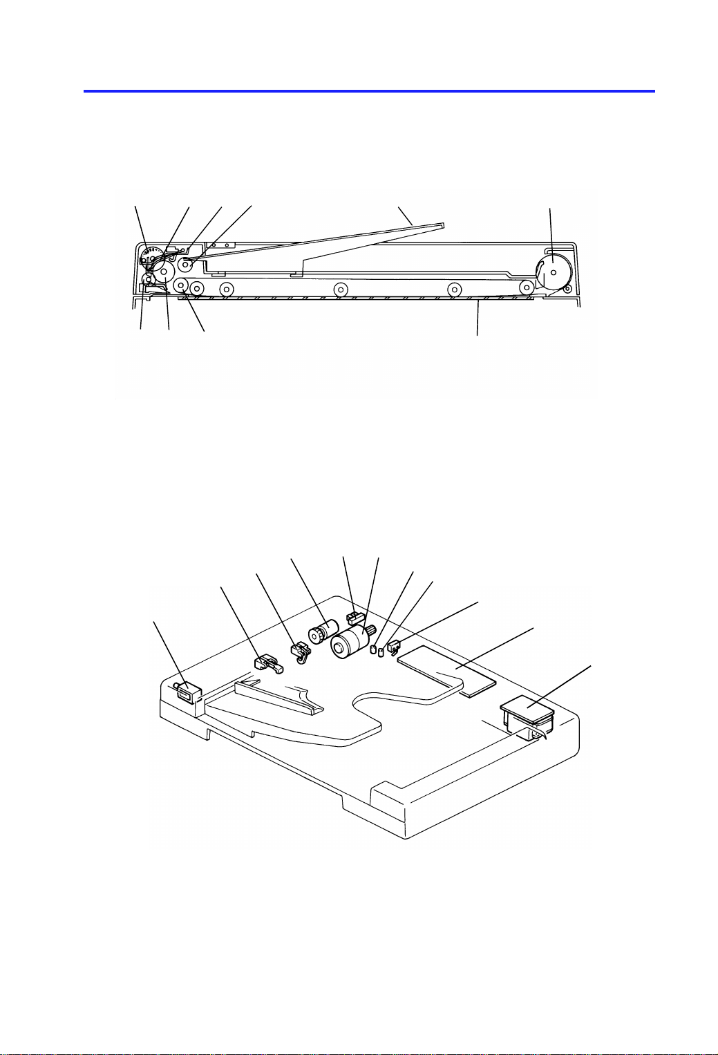
2.1 MECHANICAL COMPONENTS
1
234 65
8
910
7
1. Pulse Generator Disk
2. Friction Belt
3. Pick-up Lever
4. Pick-up Roller
5. Original Table
6. Exit Roller
7. Transport Belt
8. Transport Belt Roller
9. Feed Roller
10. Relay Roller
2.2 ELECTRICAL COMPONENTS
2
1
4
3
5
6
7
8
10
11
1. Pick-up Solenoid
2. Registration Sensor
3. Original Set Sensor
4. Feed Clutch
5. Pulse Generator Sensor
6. DF Motor
7. Insert Original Indicator
8. Original Misfeed Indica to r
9. Lift Switch
10. DF Main Board
11. DF Transformer
2
Page 4

15 January 1992 ELECTRICAL COMPONENT DESCRIPTIONS
3. ELECTRICAL COMPONENT DESCRIPTIONS
SYMBOL NAME FUNCTION LOCATION
Motor
M1 DF Drives all the document feeder components. 6
Solenoid
SOL1 Pick-up Solenoid Energizes to press the pick-up lever against
the stack of originals in preparation for
original feed-in.
Clutch
CL1 Feed Clutch Turns on to transmit the main motor rotation
to the feed roller.
Switch
SW1 Lift Switch Informs the CPU when the DF is lifted and
also serves as the misfeed reset switch for
the DF.
1
4
9
Sensors
S1 Pulse Generator
Sensor
S2 Original Set
Sensor
S3 Registration
Sensor
Printed Circuit Board
PCB1 DF Main Board Controls all DF functions. 10
Transformer
TR1 DF Transformer Steps down the wall voltage to 25 volts ac. 11
LEDs
LED1 Original Misfeed
Indicator
LED2 Insert Original
Indicator
Supplies timing pulse to the DF main board. 5
Informs copier CPU that originals have been
placed and causes the Insert Original
indicator to go out.
Sets original stop timing and checks for
original misfeeds.
Turns on when an original is misfed. 8
Turns off when the originals are inserted into
the original table.
3
2
7
3
Page 5
POWER DISTRIBUTION 15 January 1992
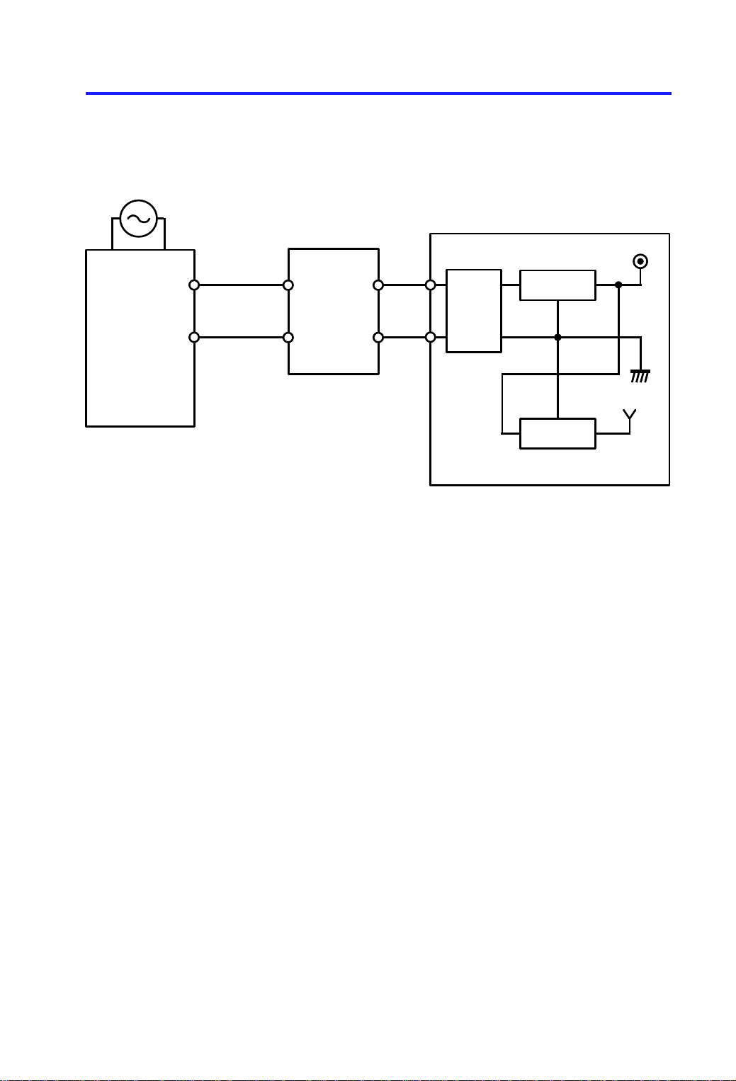
4. POWER DISTRIBUTION
+24 V (VA)
Regulate
+5 V (VC)
Regulate
AC Drive Board
(PCB2)
115 Vac
220–230 Vac
240 Vac
DF
Transformer
(TR1)
25 Vac
Rectify
&
Smooth
DF Main Board (PCB1)
The document feeder uses two dc powe r levels: +24 volts, and +5 volts.
When the main switch is turned on, th e DF t ran sfo rmer receives the wall
outlet ac power thro ugh the ac drive board and outputs 25 volt s a c to th e DF
main board. Then, the dc power supply circuit on the DF main board con vert s
the 25 volts ac input to +24 volts and +5 volts.
+24 volts is used by the DF moto r, th e pick-up solenoid, and the feed clutch.
+5 volts is used by other electrical components.
4
Page 6

15 January 1992 BASIC OPERATION
5. BASIC OPERATION
When the main switch is turned on, the DF CPU sends the "DF installed"
signal to the copier CPU. Receivin g th is sig nal, the copier CPU recognizes
that the document fee de r is inst alle d an d sen ds the "DF confirmed" signal to
the DF CPU.
When originals are placed on the origin al ta ble, the Insert Original indicat or
turns off and the DF CPU sends the "origin al set" signal to the copier CPU to
inform that the orig ina ls h ave bee n set .
When the Start key is pressed, the copier CPU sends the "feed-in" signal to
the document feeder. On rece ipt of th is signa l, th e DF CP U energizes the DF
motor, the pick-up sole no id, and the fee d clut ch to fee d-in the bottom sheet of
the original stack onto the exposu re glass. The pick-up solenoid, and the
feed clutch remain energized until t he origin al’s leading edge reaches the
registration sensor. The DF motor tu rns off shortly after the original’s trailing
edge passes the registration sensor. Then, the DF moto r pau ses an d
reverses for a moment to alig n the edge of the original with th e scale .
The scanner starts, and the start timing does not depend on the progress of
the original through the DF. When the sca nner reaches the return position,
the copier CPU sends the "origina l chan ge" sign al to the DF CPU in order to
exchange the origina l wit h th e ne xt original.
5
Page 7
Fiber Optics
Fiber Optics
INTERFACE CIRCUIT 15 January 1992
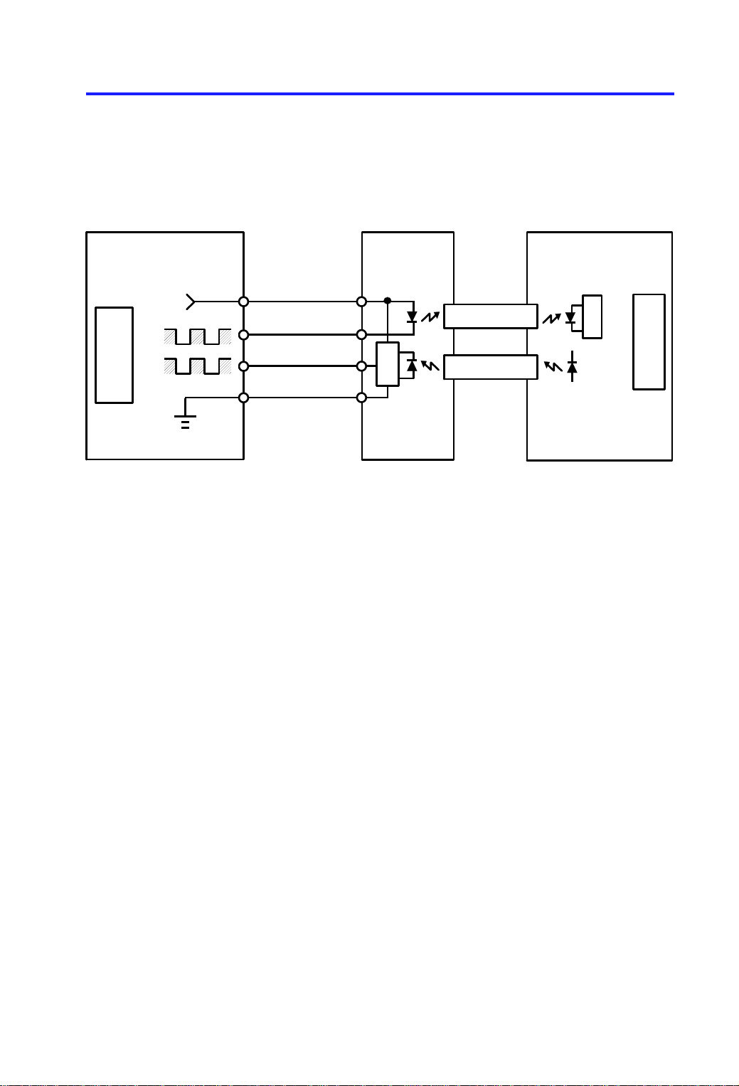
6. INTERFACE CIRCUIT
Copier Main Board (PCB1) DF Interface Board (PCB4)
CPU
TXD
RXD
+5V
CN120-2
CN120-5
CN120-4
CN120-1
CN2-1
CN2-4
CN1
CN2-2
CN2-3
DF Main Board (PCB1)
RXD
CN118
TXD
The copier CPU and the DF CPU communicate via the interface board and
fiber optics. The interfa ce bo ard chan ge s the opt ical sign als to electrical
signals (and vice versa).
CPU
6
Page 8

[A]
[D]
15 January 1992 ORIGINAL FEED
7. ORIGINAL FEED
7.1 ORIGINAL PICK-UP MECHANISM
[C]
[B]
After setting the origina ls on th e orig ina l tab le, the origin als con ta ct th e feeler
[A] of the original se t sen sor an d cau se the feeler to move out of the sen sor.
The DF CPU then sends the origina l set signal to the copier CPU to inform it
that the document fee de r will be used . When the Start key is pressed, th e
pick-up solenoid [B] is energized. The original stack is then pressed betwe en
the pick-up lever [C] and pick-up roller [D]. The rota tio n of the pick-up roller
advances the bottom original.
7
Page 9

[B]
ORIGINAL FEED 15 January 1992
7.2 ORIGINAL SEPARATION MECHANI SM
[A]
[C]
[E]
[B]
[D]
[D]
[C]
[A]
[E]
The feed roller [A] and the friction belt [B] are use d to fee d-in and sepa rat e
the originals [C]. Only the bottom original is fed because the friction belt
prevents any other origin als fro m f eeding.
Original feed starts when the pick-up lever [D] presses the original stack and
the rotation of the pick-up roller [E] advances the bott om orig inal of the stack.
The feed roller moves the original pa st th e friction belt because the driving
force of the feed roller is greater than the resistance of the friction belt. The
friction belt prevents multiple feeds becau se th e resist ance of the frictio n belt
is greater than the friction between original she et s.
8
Page 10

15 January 1992 ORIGINAL FEED
7.3 ORIGINAL FEED-IN MECHANISM
[C]
[E]
[A]
[F]
The DF motor [A] drives the feed roller [B], the pick-up roller [C] , th e rela y
rollers [D], and the transport belt roller [E] via timing belts and a gear train.
The feed roller and the pick-up roller are controlled by the feed clut ch [F] , but
the relay rollers and the transport roller are directly driven by the DF motor.
The idler rollers [G] on the feed roller shaf t are free from the shaft.
[G]
[D]
[B]
When the Start key is pressed, the DF mot or is energized and the relay
rollers and transport belt roller start tu rnin g. 100 millisecon ds af ter t he DF
motor starts turning, the pick-up solenoid and th e fe ed clu tch is energ ized.
The pick-up and feed rollers then start turning and carry the origin al between
the relay rollers and the idler rollers. The pick-up solen oid and the fee d clutch
are de-energized when the origin al’s leading edge passes through the
registration sensor.
The DF motor remains energized to deliver the original to the exposure glass
until a certain number of pulses (10 to 25 pulse s) aft er the original’s trailing
edge passes through the regist rat ion sensor. Then, the DF motor pauses and
reverses for 15 pulses to alig n th e ed ge of th e orig inal with the scale.
To feed the second original, the DF mot or sta rts rot at ing when the scanner
reaches the return position. (The copier CPU sends the original chang e
signal to the DF CPU.) At this time, the transport belt start s carrying the first
original on the exposure glass to the exit rolle r. The timing tha t whe n th e
pick-up solenoid and the fee d clut ch are ene rgize d for the second original
depends on the length of the first origin al dete cte d by th e reg istra tio n sen sor.
9
Page 11

[D]
ORIGINAL FEED 15 January 1992
7.4 ORIGINAL FEED-OUT ME CHANI SM
[A] [B] [C]
The exit rollers are driven by the DF motor through a gear train , the tra nsp ort
belt roller, the transport be lt [A ], the transport belt idler roller [B], and the exit
roller drive belt [C]. When the DF CPU receives the original change signal
from the copier CPU, the DF motor starts turning. Simult aneo usly, the
transport belt carries the original to the exit rolle rs [D] an d the exit rollers ta ke
over the original feed-out.
10
Page 12

Forward: +24 V
Reverse: 0 V
Forward: 0 V
Reverse: +24 V
15 January 1992 ORIGINAL FEED
7.5 DF MOTOR CIRCUIT
DF Main Board (PCB1)
+24 V (VA)
Original
Change
Signal
R x D
CPU
Forward
Reverse
ON/OFF
GATE
IC
Forward
Reverse
DRIVER
IC
+5 V (VC)
CN117-1
CN117-2
DF Motor
(M1)
Timing Pulse
Pulse
Generator
Sensor
(S1)
A 24 volt dc motor is used as the DF moto r. When the CPU receives the feed
signal from the copier, the CPU out pu ts the ON signal and the Forward signal
to the gate IC. On receipt of the forward signal from the gate IC, the driver IC
outputs 24 volts to CN117-1 and 0 volt s to CN11 7-2 . This cau ses the DF
motor to start turning in the forward direction .
Within 10 to 25 pulses after the original’s trailing edge passes throu gh the
registration senso r, the CPU stops sending the ON sign al and the Forward
signal. The DF motor stops turnin g. Then , the CPU ou tput the ON signa l and
the reverse signal for 15 pulses. The n, the driver IC ou tp ut s 0 volts to
CN117-1 and +24 volts to CN117-2 to reverse the DF motor.
11
Page 13

ORIGINAL FEED 15 January 1992
7.6 ORIGINAL FEED AND MIS FEE D DETE CTI ON TI MI NG
Feed Signal (Start key) Original Change Signal
0 500 1000 0 500 1000
Timing (msec.)
10 to 25 pulses
DF Motor
10 to 25 pulses
❋
15 pulses
J0
Pick-up Sol.
and
Feed Clutch
100 msec
15 pulses
J0
J0
Registration
Sensor
500 msec
500 msec
1,500 msec
❋: The timing depends on the length of the first original.
1,500 msec
The above chart shows the origina l fee d timin g for the origin al size of A4
lengthwise or 8.5" x 11" and the detection timing.
The registration sensor is used for a misfe ed det ect ion. If the DF CPU
detects that a misfeed exists, the DF CPU lights the Origina l Misfeed
indicator and sends the origin al misfe ed signa l to th e cop ier CPU. Then, the
copier CPU lights the check paper p ath an d th e Misfe ed Loca tio n Number
(JO) on the operation panel. When the main switch is turn ed on, the DF CPU
checks the registration sensor output for initial origina l misfee d. During the
original feed-in, the DF CPU perfo rms two kind s of original misfeed detection:
1. Whether the registration senso r is actua ted with in 500 milliseco nds aft er
the pick-up solenoid and the feed clut ch turn on.
2. Whether the original has passed through the registration sensor 1,500
milliseconds after the registration sensor has been actuated.
12
Page 14

15 January 1992 INSTALLATION PROCEDURE
8. INSTALLATION PROCEDURE
NOTE: This procedure is for machine code A077/A078 copiers.
8.1 INSTALLATION
[A]
[B]
[D]
CAUTION: When installing the DF, make sure that the copie r is
unplugged.
1. Remove the platen cover [A] from the copier.
2. Remove the strips of tape from the DF.
CAUTION: This procedure (step 3) must be done only in 240 volts
areas.
[E] 230~240 V
[C] 220~230 V
3. Perform the conversion fro m 220 ~23 0 V to 240 V as follo ws:
1) Remove the main board cover [B ] (2 screws).
2) Disconnect the connector for 2 20~230 V [C] (Black Wire) from ac
harness connector [ D] and reconnect the connector fo r 240 V [E]
(White Wire) to the ac harness connect or.
3) Reinstall the cover.
13
Page 15

[E]
INSTALLATION PROCEDURE 15 January 1992
[G]
[A]
[C]
[B]
[D]
[F]
4. Insert the DF [A] into the hole s [B] of th e copier up pe r cover.
5. Secure the DF to the copier (2 thumb screws [ C]).
6. Remove the seal [D] from th e ou tle t of the copier.
7. Plug in the optics fiber cable [E] to the DF and the copier as shown.
8. Plug in the power supply cord [F] of the DF to the outlet of the copier rear
cover as shown.
9. Install the orig ina l t ab le [G ] as shown.
10. Check the operatio n of the DF.
14
Page 16

[D] 230~240 V
[B] 220~230 V
15 January 1992 INSTALLATION PROCEDURE
8.2 220 ~ 230 V/240 V CONVERSION
[A]
[C]
1. Remove the main board cover [A] (2 screws).
2. Disconnect the connect or for 2 20~230 V [B] (Black Wire) from ac harness
connector [C] and reconne ct th e con nector for 240 V [D] (White Wire) to
the ac harness connector.
3. Reinstall the cove r.
15
Page 17

REPLACEMENT AND ADJUSTMENT 15 January 1992
9. REPLACEMENT AND ADJUSTMENT
9.1 TRANSPORT BELT REPLACEMENT
[A]
[B]
[E]
[F]
[D]
[H]
1. Turn off the main switch.
2. Remove the original table [A].
3. Remove the DF [B] from t he copier (2 knob screws, 1 power supply cord
and 1 optics harness).
4. Remove the grip guide [C] (2 screws).
[I]
[G]
[C]
5. Remove the transformer cove r [D] (3 screws), DF mot or cove r [E]
(4 screws) and main board cover [F] (2 screws).
6. Remove the transpo rt belt assembly [G] (5 screws and 1 drive belt [H]).
NOTE: When installing the tra nsport belt assembly, make sure that the
positioning pin [I] fit in the DF frame.
16
Page 18

15 January 1992 REPLACEMENT AND ADJUSTMENT
[A]
[B]
7. Remove the transpo rt rolle r holder [A] (1 screw, 1 snap ring and 1
bushing).
8. Pull out the transport belt [B].
NOTE: After reinstalling the transport belt, make sure that the bushings
of the transport rollers set corre ctly and tra nsport belt turns
smoothly.
17
Page 19

[C]
REPLACEMENT AND ADJUSTMENT 15 January 1992
9.2 FEED-IN UNIT REMOVAL
[A]
[B]
1. Turn off the main switch.
2. Remove the transport belt assembly. (See Transport Belt Replacement.)
3. Remove the left hinge bracket [A] (4 screws and 1 connector).
4. Disconnect five connectors from th e main board [B] (CN111, CN113,
CN115, CN116 and CN117).
5. Remove the feed-in unit [C] (5 screws).
NOTE: When reinstalling the feed-in unit , th e harne ss mu st be
positioned underneath the right hinge bracket.
18
Page 20

[C]
15 January 1992 REPLACEMENT AND ADJUSTMENT
9.3 PICK-UP ROLLER REPLACEMENT
[D]
[B]
[A]
1. Turn off the main switch.
2. Remove the feed-in unit . (Se e Feed-in Unit Removal.)
3. Remove the DF motor [A] (2 screws an d 1 timin g be lt [B ]).
4. Remove the pick-up roller [C] (2 E-rings and 1 bushing) from the shaft [D].
19
Page 21

REPLACEMENT AND ADJUSTMENT 15 January 1992
9.4 FEED ROLLER REPLACEMENT
[E]
[I]
[G]
[F]
[B]
[C]
[A]
[D]
1. Turn off the main switch.
2. Remove the feed-in unit . (Se e Feed-in Unit Removal.)
3. Remove the feed roller timing belt [A] , fe ed roller ge ar [B ] (1 E-rin g an d 1
spring pin [C]) and 1 bushing [D].
NOTE: Be careful not to loose the spring pin.
4. Slide the feed roller shaft [E] toward front side and remove the feed clutch
[F] (1 E-ring and 1 connector).
5. Take out the feed roller shaft (1 spacer and 1 bushing ----- from rear side).
6. Remove the feed roller [G] from th e shaft (3 side rollers [H], 7 E-rings and
1 spring pin [I]).
NOTE: Be careful not to loose the spring pin.
20
Page 22

15 January 1992 REPLACEMENT AND ADJUSTMENT
9.5 FRICTION BELT REPLACEMENT
[A]
[C]
[B]
1. Turn off the main switch.
2. Remove the friction belt asse mbly [A] (1 screw).
3. Remove the friction belt [B ] (2 springs, 1 pin).
NOTE: When installing the frict ion belt assembly, make sure the feed
roller [C] is set in the correct position. (See illustra tio n. )
21
Page 23

[D]
REPLACEMENT AND ADJUSTMENT 15 January 1992
9.6 PICK-UP SOLENOID ADJUSTMENT
[F]
[E]
[B]
[C]
[A]
1. Turn off the main switch.
2. Remove the feed-in unit . (Se e Feed-in Unit Removal.)
3. Loosen two screws [A] secu ring the pick-up solenoid [B].
4. Place the 1.2 mm thickness gauge [C] between the plunger and the
solenoid.
5. Turn the solenoid leve r [D] clockwise until the plunger touches the
thickness gauge. Just at this po int , tig hten two screws.
6. Make sure that the pick-u p leve r [E] is to uch ing the pick-up roller [F] when
the plunger is pushed. If not, repeat step 3 to 5.
7. Reassemble the DF.
8. Turn on the main switch and check the original feed-in operation.
22
 Loading...