

Page 1

IMPORTANT SAFETY NOTICES
PREVENTION OF PHYS ICAL INJURY
1. Before disassembling or asse mblin g pa rts of the copie r and perip herals,
make sure that the copier power cord is unplu gg ed.
2. The wall outlet should be near the copier an d easily accessible.
3. Note that some compo ne nt s of th e copier and the paper tray unit are
supplied with electrical voltage even if the main switch is turned off.
4. If any adjustment or operat ion check has to be made with exterior covers
off or open while the main switch is turned on, keep hands away from
electrified or mechanically drive n comp on ents.
5. The inside and the met al parts of the fusing unit become extre mely ho t
while the copier is operat ing . Be ca ref ul to avoid touching those
components with your bare hands.
HEALTH SAFETY CONDITIONS
1. Never operate the copier without the ozon e filt er inst alle d.
2. Always replace the ozone filter with the specified one at the specifie d
interval.
3. Toner and developer are non-toxic, but if you get either of them in your
eyes by accident, it may cause temp ora ry e ye disco mfo rt. Try to remove
with eye drops or flush with wat er as first aid. If un succe ssfu l, ge t med ical
attention.
OBSERVANCE OF ELECTRICAL SAFETY STANDARDS
1. The copier and its peripheral must be installed and maintained by a
customer service represen tative who has completed the training course
on those models.
2. The RAM pack has a lithium battery which can explod e if hand led
incorrectly, replace only with same RAM pack. Do not recharge, or burn
this battery. Used RAM pack must be handle d in accordance with local
regulations.
Page 2

SAFETY AND ECOLOGICAL NOTES FOR DISP OS AL
1. Do not incinerate the toner cartridge or the used toner. Toner dust may
ignite suddenly when exposed to open flame.
2. Dispose of used tone r, developer, and organic photoconductors
according to local regulations. (These are non-toxic supplies.)
3. Dispose of replaced parts in acco rda nce with local regulations.
Page 3

SECTION 1
OVERALL MACHINE
INFORMATION
Page 4

15 January 1992 SPECIFICATIONS
1. SPECIFICATIONS
Configuration : Desk top
Copy Process: Dry electrostatic transfer system
Originals: Sheet/Book
Original Size: Maximum A3/11" x 17" – A077/A078 copiers
B4/10" x 14" – A076 copier
Copy Paper Size: Maximum – B4/10" x 14"
Minimum – A5 (lengthwise)/51/2" x 81/2"
Copy Paper Weight: Paper tray feed – 52 to 90 g/m2 (14 to 24 lb)
Manual feed – 52 to 157 g/m2 (14 to 42 lb)
Reproduction Ratios: 2 Enlargement and 3 Reduction
(A077/A078 copiers only)
A4 Version Letter Version
Enlargement
Full size 100% 100%
Reduction
Zoom: From 61% to 141% in 1% steps
(A077/A078 copiers only)
Copying Speed: 13 copies/minute (A4 leng th wise/81/2" x 11")
10 copies/minute (B4/10" x 14")
Warm-Up Time: 30 seconds (at 20°C/68°F)
First Copy Time: 9 seconds (A4 lengthwise/81/2" x 11")
Copy Number Input: Quantity keys, 1 to 99 (count up)
Manual Image Density
Selection:
7 steps
141%
122%
93%
82%
71%
129%
121%
93%
74%
65%
1-1
Page 5

SPECIFICATIONS 15 January 1992
Automatic Reset: 1 minute standard setting; can also be set to 3
minutes or no auto reset.
Automatic Start: When the Start key is pressed bef ore the copier
finishes the warm-up cycle, the copier starts
making copies as soon as the warm-up cycle is
completed.
Paper Capacity: Paper tray – 250 sheets
Manual feed table – 1 sheet
Toner Replenishment: Cartridge exchange (320 g/cartridge)
Copy Tray Capacity: 100 sheets (B4/10" x 14" or smaller)
Power Source: 110V / 60Hz/ 15 A (fo r Taiwan)
115V/ 60Hz/ 15A (for North America)
220~230V/ 50Hz/ 8A (for Europe)
220V/ 60Hz/ 8A (for Middle East)
240V/ 50Hz/ 8A (for Europe)
(Refer to the serial number plate (rating plat e) to
determine the power source required by the
machine.)
Power Consumption:
Noise Emission:
Copier Only With DF
Maximum 1.4 kVA 1.5 kVA
Warm-up 0.60 kVA (average) 0.62 kVA (average)
Copy cycle 0.81 kVA (average) 0.86 kVA (average)
Stand-by 0.16 kVA (average) 0.18 kVA (average)
Copier Only With DF
Maximum 58 db 60 db
Warm-up Less than 40 db Less than 40 db
Copy cycle Less than 55 db Less than 55 db
1-2
Page 6

15 January 1992 SPECIFICATIONS
Dimensions:
Width Depth Height
Copier only
With DF
A076/A077
copiers
A078 copier 830 mm (32.7") 582 mm (23.0") 503 mm (19.9")
A077 copier 830 mm (32.7") 582 mm (23.0") 463 mm (18.3")
A078 copier 830 mm (32.7") 582 mm (23.0") 563 mm (22.2")
830 mm (32.7") 582 mm (23.0") 403 mm (15.9")
Weight: Copier only – A076/A077 Copiers 43 kg (94.8 lb)
A078 Copier 51 kg (112.5 lb)
With DF – A077 Copier 50 kg (110.3 lb)
A078 Copier 58 kg (127.9 lb)
Optional Equipment: Document feeder
Key counter
Drum anti-condensation heater
Optics anti-condensation heater
• Specifications are subject to chan ge witho ut notice.
1-3
Page 7
COPY PROCESSES AROUND THE DRUM 15 January 1992
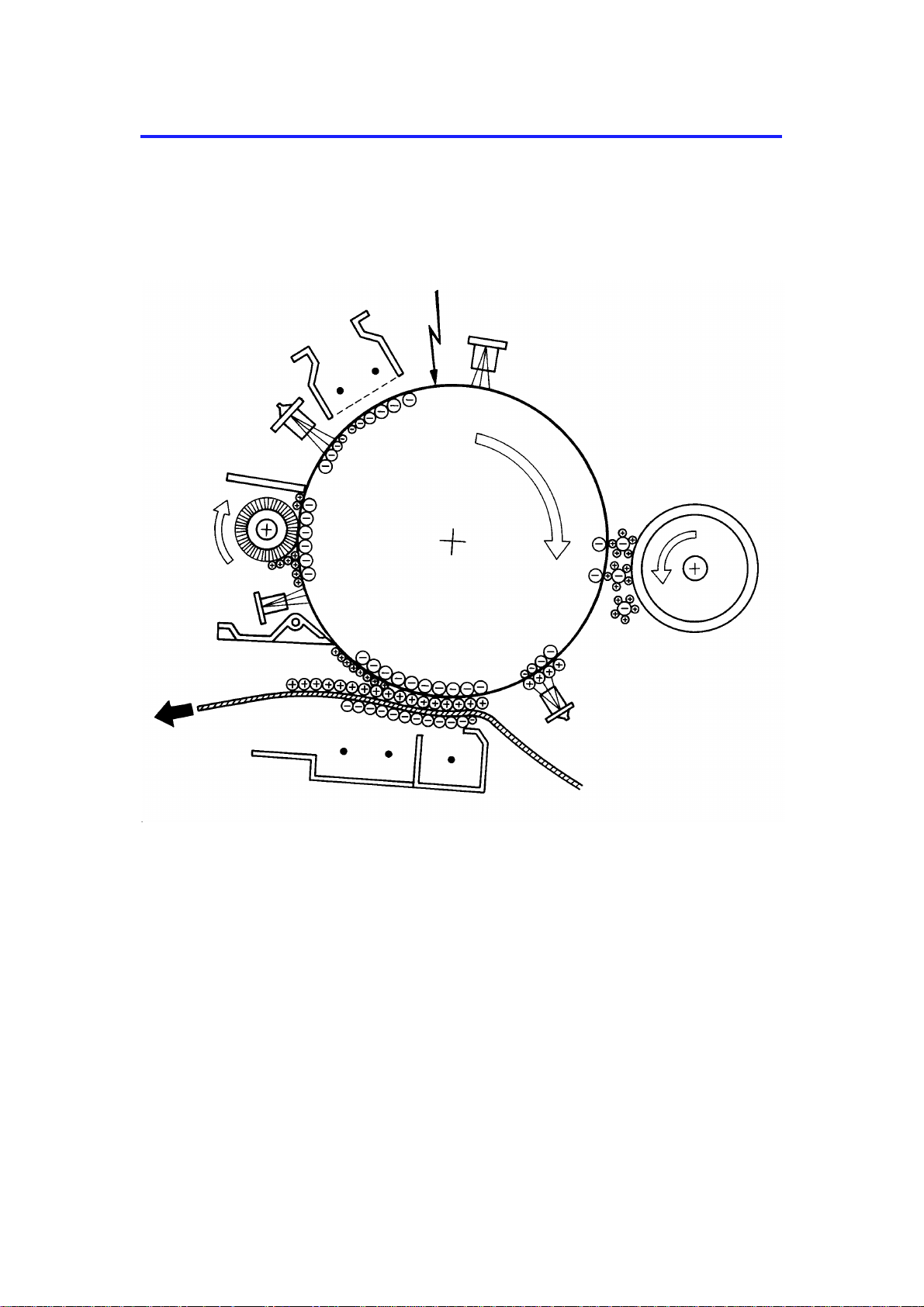
2. COPY PROCESSES AROUND THE DRUM
2. EXPOSURE
1. DRUM CHARGE
3. ERASE
9. QUENCHING
4. DEVELOPMENT
8. CLEANING
7. PAPER
SEPARATION
5. PRE-TRANSFER LAMP
(PTL)
6. IMAGE TRANSFER
1-4
Page 8

15 January 1992 COPY PROCESSES AROUND THE DRUM
1. DRUM CHARGE
In the dark, the charge corona unit gives a uniform negative charge to the organic
photoconductive (OPC) drum. The charge remains on the surface of the drum because the
OPC drum has a high electrical resistance in the dark.
2. EXPOSURE
An image of the original is reflected to the OPC drum surface via the optics assembly. The
charge on the drum surface is dissipated in direct proportion to the intensity of the reflected
light, thus producing an electrical latent image on the drum surface.
3. ERASE
The erase lamp illuminates the areas of the charged drum surface that will not be used for
the copy image. The resistance of the drum in the illuminated areas drops and the charge on
those areas dissipates.
4. DEVELOPMENT
Positively charged toner is attracted to the negatively charged areas of the drum, thus
developing the latent image. (The positive triboelectric charge is caused by friction between
the carrier and toner particles.)
5. PRE-TRANSFER LAMP (PTL)
The PTL illuminates the drum to remove all negative charge from the exposed areas of the
drum. This prevents the toner particles from being reattracted to the drum surface during
paper separation and makes paper separation easier.
6. IMAGE TRANSFER
Paper is fed to the drum surface at the proper time so as to align the copy paper and the
developed image on the drum surface. Then, a strong negative charge is applied to the back
side of the copy paper, producing an electrical force which pulls the toner particles from the
drum surface to the copy paper. At the same time, the copy paper is electrically attracted to
the drum surface.
7. PAPER SEPARATION
A strong ac corona discharge is applied to the back side of the copy paper, reducing the
negative charge on the copy paper and breaking the electrical attraction between the paper
and the drum. Then, the stiffness of the copy paper causes it to separate from the drum
surface. The pick-off pawls help to separate paper.
8. CLEANING
The cleaning brush removes most of the toner on the drum and loosens the remainder. Then
the cleaning blade scrapes off the loosened toner.
9. QUENCHING
Light from the quenching lamp electrically neutralizes the surface of the drum.
1-5
Page 9
COPY PROCESS CONTROL 15 January 1992
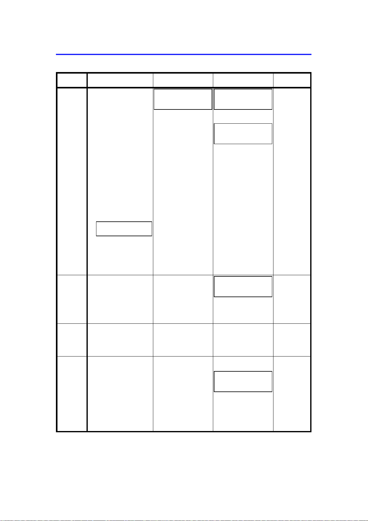
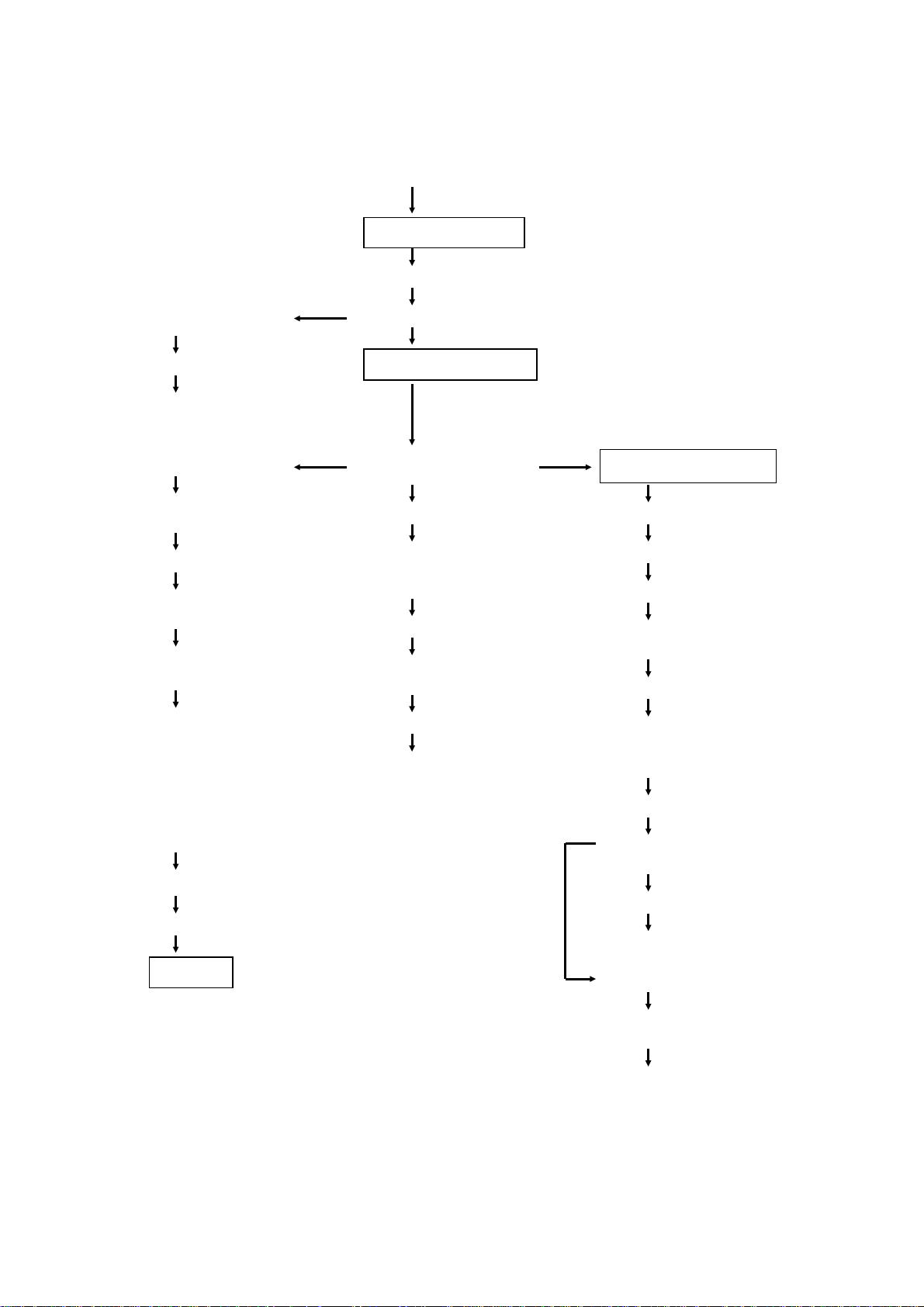
3. COPY PROCESS CONTROL
Image
Density
Control
Toner
Density
Detection
Residual
Voltage
(Vr)
Detection
Between
Copies
Grid Voltage
1. Manual image
density mode
Standard ima ge
density grid voltage
+ +
Manual image density
level fact or
+
Drum residual voltage
(Vr) correction factor
+
Drum temperature
correction factor
2. Auto imag e density
mode
Standard ima ge
density grid voltage
+
Auto image density
level factor (SP34 )
+
Drum residual voltage
(Vr) correction factor
+
Drum temperature
correction factor
Standar d I D sensor gri d
voltage
+
Drum wear correction
factor (SP57)
Standar d I D sensor gri d
voltage
+
Drum wear correction
factor (SP57)
0 volts (Fix ed) Ex p osure lamp turns
Exposure Lamp
Voltage
Base exposure lamp
voltage (Manual or
ADS mode) (SP48)
Reproduct ion ratio
correction factor
(A077/A078 copiers
only)
+
Drum temperature
correction factor
+
Drum residual voltage
(Vr) correction factor
Same as image
density co ntrol
Same as image
density co ntrol
off.
Developmen t Bia s
Voltage
Base bias voltage
factor (Manual or
ADS mode [SP34])
+
Image bias voltage
adjustment factor
(SP37)
+
Drum residual voltage
(Vr) correction factor
+
Drum temperature
correction factor
Note:
Base bias voltage at
manual ID level 7 can
be adjusted by SP50.
Depends on ID
sensor b ias settin g
(SP33)
Note:
For initial 499 copies
bias volt age is
increased by –20 volts.
0 volts (Fixed) Full erase
–160 volt s (F ixed)
+
Base bias voltage
adjustment factor
(SP37)
+
Drum residual voltage
(Vr) correction factor
+
Drum temperature
correction factor
Erase Lamp
Depends on
paper size
and
reproducti on
ratio.
ID sensor
pattern eras e
(Vsg
detectio n:
Full erase)
(All LEDs ON)
Full erase
(All LEDs ON)
NOTE: The boxed item can be adjusted by SP mode.
1-6
Page 10
12
15 January 1992 MECHANICAL COMPONENT LAYOUT
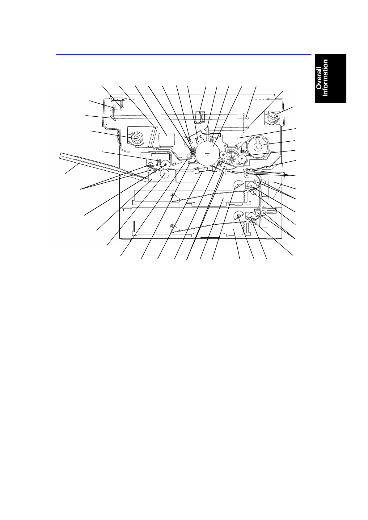
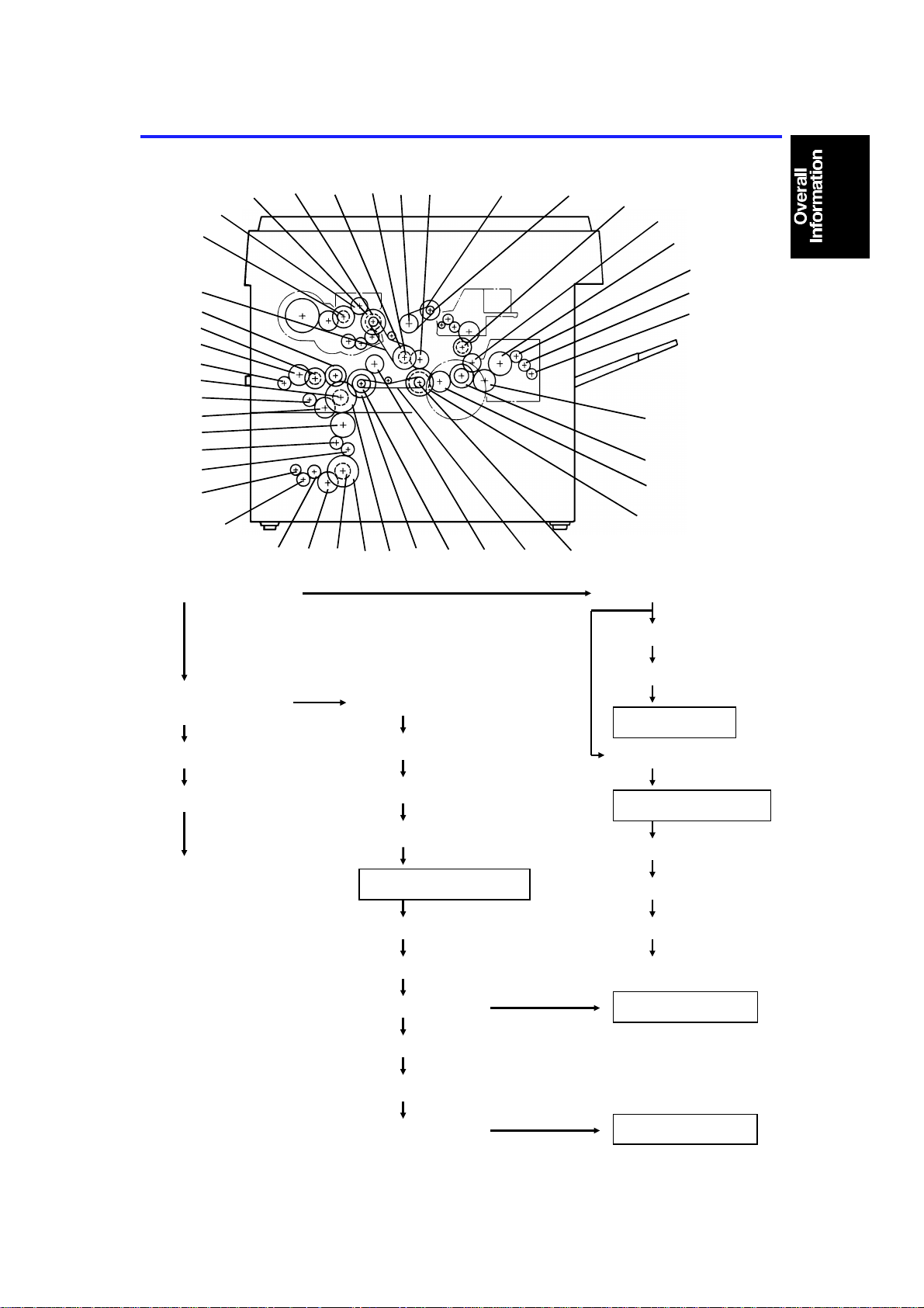
4. MECHANICAL COMPONENT LAYOUT
17
18
20 21 22
19
23 24 25
26 27
28
29
16
30
15
14
31
32
13
33
34
35
11
36
37
10
38
39
9
40
8
7
1. 1st Semicircular Pick-up
rollers
2. 1st Paper Tray
3. Registration Rollers
4. Pre-transfer Lamp (PTL)
5. Transfer and Separation
Corona Unit
6. Pick-off Pawls
7. Cleaning Unit
8. Pressure Roller
9. Fusing Unit
10. Hot Roller
11. Exit Rollers
12. Copy Tray
13. Hot Roller Strippers
14. Exhaust Blower Motor
15. 3rd Mirror
16. 2nd Mirror
17. 1st Mirror
18. Ozone Filter
19. Used Toner Tank
20. Cleaning Brush
21. Cleaning Blade
22. Quenching Lamp
23. Charge Corona Unit
24. Lens
25. 6th Mirror
26. Erase Lamp
27. Drum
28. 4th Mirror
29. 5th Mirror
30. Optics Cooling Fan
31. Developer Tank
32. Toner Supply Unit
123456
33. Development Unit
34. Manual Feed Roller
35. 1st Relay Rollers
36. Manual Feed Table
37. 2nd Relay Rollers
38. 1st Paper Feed Roller
39. 1st Torque Roller
40. 2nd Feed Relay Rollers
(A078 copier only)
41. 2nd Torque Roller
(A078 copier only)
42. 2nd Paper Feed Roller
(A078 copier only)
43. 2nd Semicircular Pick-up
Rollers (A078 copier only)
44. 2nd Paper Tray
(A078 copier only)
424344
41
1-7
Page 11
ELECTRICAL COMPONENT LAYOUT 15 January 1992
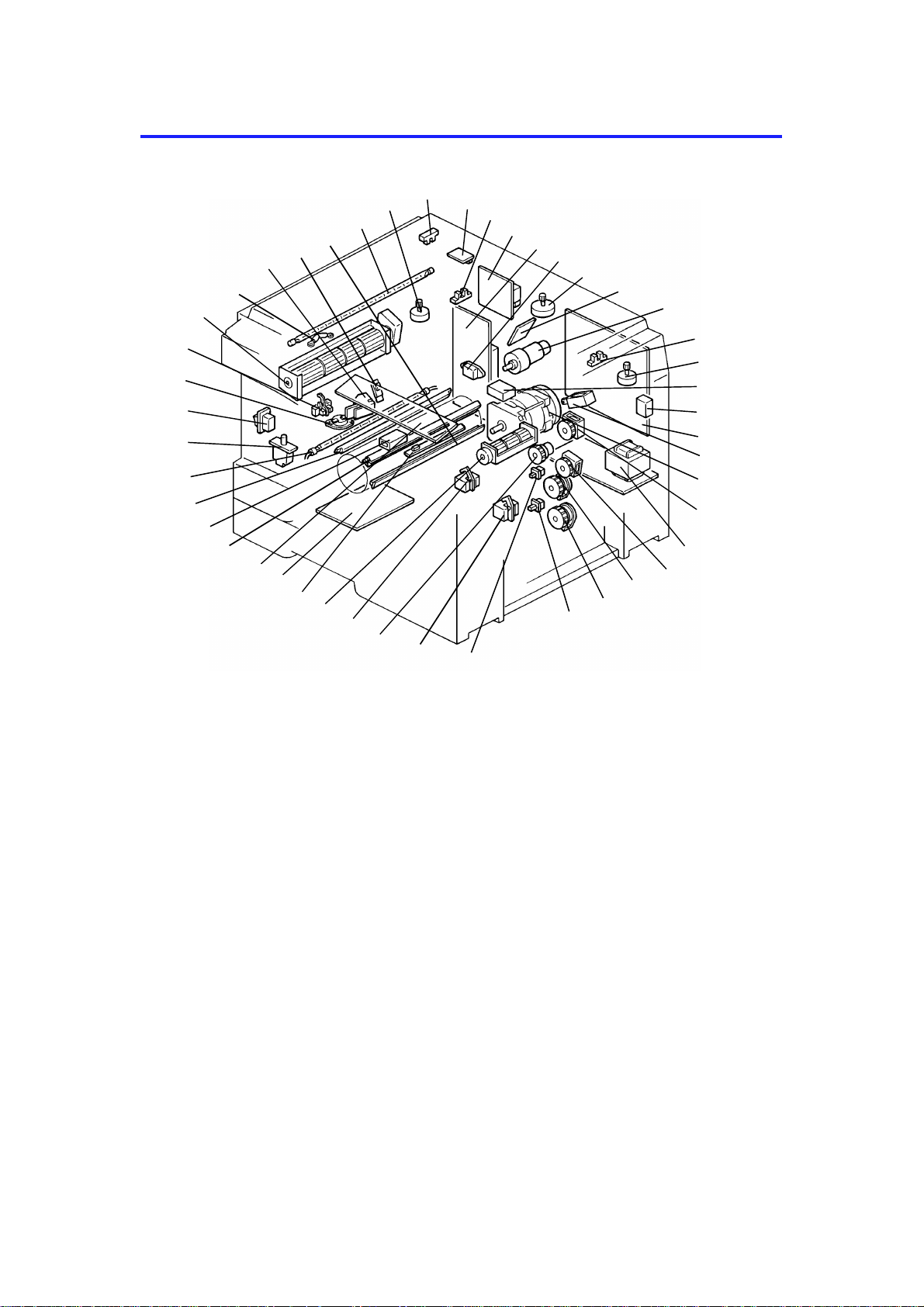
5. ELECTRICAL COMPONENT LAYOUT
21
20
19
18
17
16
15
14
13
12
11
10
9
8
7
6
5
1. 1st Paper Tray Switch
2. Relay Sensor
3. Registration Clutch
4. Registration Sensor
5. Optics Cooling Fan Motor
6. Image Density Sensor
(with drum thermistor)
7. Power Pack-TC/SC
8. Operation Panel Board
9. Erase Lamp
10. Total Counter
11. Quenching Lamp
12. Fusing Lamp
13. Front Cover Safety Switch
14. Main Switch
15. Fusing Thermoswitch
16. Exit Sensor
17. Exhaust Blower Motor
24
23
22
25
26
27
4
3
2
18. Optics Thermofuse
19. Auto Image Density Sensor
20. Fusing Thermistor
21. Pre-transfer Lamp
22. Exposure Lamp
23. Lens Motor
(A077/A078 copiers only)
24. Scanner Home Position
Sensor
25. DF Interface Board
(A077/A078 copiers only)
26. Lens Home Position
Sensor
(A077/A078 copiers only)
27. Power Pack-CC/Grid/Bias
28. AC Drive Board
29. Fusing Triac (115 V only)
30. Scanner Motor
31. Drum Motor Board
1
28
29
30
31
32
33
34
35
36
37
38
39
40
41
42
43
44
45
32. Drum Motor
33. 4th/5th Mirror Home
Position Sensor
(A077/A078 copiers only)
34. 4th/5th Mirror Motor
(A077/A078 copiers only)
35. Main Motor Capacitor
36. Key Counter (Option)
37. Main Board
38. Development Clutch
Solenoid
39. Main Motor
40. Toner Supply Clutch
41. DC Power Supply Board
42. Relay Roller Clutch
43. 1st Paper Feed Clutch
44. 2nd Paper Feed Clutch
(A078 copier only)
45. 2nd Paper Tray Switch
(A078 copier only)
1-8
Page 12

15 January 1992 ELECTRICAL COMPONENT DESCRIPTIONS
6. ELECTRICAL COMPONENT DESCRIPTIONS
Motors
SYMBOL NAME FUNCTION
Drives all the main unit components except for the
M1 Main Motor
M2 Scanner Motor Drives the scanners (1st and 2nd). (dc stepper) 30
M3 Lens Motor
M4
M5
M6
M7 Drum Motor Drives the drum. (dc servo) 32
4th/5th Mirror
Motor
Optics Cooling
Fan Motor
Exhaust Blower
Motor
optics unit, drum unit and fans.
(115/220–230/240 Vac [ac synchronous])
Moves the lens position according to the selected
magnification. (dc stepper)
… A077/A078 copiers only
Positions the 4th/5th mirrors according to the
selected magnification. (dc stepper)
… A077/A078 copiers only
Prevents built up of hot air in the optics cavity.
(24 Vdc)
Removes heat from around the fusing unit and
moves the ozone built up around the charge
section to the ozone filter. (115/220–230/240 Vac)
INDEX
NO.
39
23
34
5
17
Magnetic Clutch
SYMBOL NAME FUNCTION
MC1
Registration
Clutch
Drives the registration rollers. 3
Magnetic Spring Clutches
SYMBOL NAME FUNCTION
MSC1
MSC2
MSC3
MSC4
Toner Supply
Clutch
Relay Roller
Clutch
1st Paper Feed
Clutch
2nd Paper Feed
Clutch
Drives the toner supply roller. 40
Drives the 1st and 2nd relay rollers. 42
Starts paper feed from the 1st paper feed station. 43
Starts paper feed from the 2nd paper feed station.
… A078 copier only
Solenoid
SYMBOL NAME FUNCTION
SOL1
Development
Clutch Solenoid
Transmits the main motor drive to the
development drive gears.
INDEX
NO.
INDEX
NO.
44
INDEX
NO.
38
1-9
Page 13

ELECTRICAL COMPONENT DESCRIPTIONS 15 January 1992
Switches
SYMBOL NAME FUNCTION
SW1 Main Switch Supplies power to the copier. 14
SW2
SW3
SW4
Front Cover
Safety Switch
1st Paper Tray
Switch
2nd Paper Tray
Switch
Cuts the ac power line, when the front cover is
open.
Detects when the 1st paper tray is set. 1
Detects when the 2nd paper tray is set.
… A078 copier only
INDEX
NO.
13
45
Sensors
SYMBOL NAME FUNCTION
S1
S2
S3
S4
S5 Exit Sensor Detects misfeeds. 16
S6 Relay Sensor
S7
S8
Scanner Home
Position Sensor
Lens Home
Position Sensor
4th/5th Mirror
Home Position
Sensor
Registration
Sensor
Image Density
(ID) Sensor
Auto Image
Density Sensor
(ADS)
Informs the CPU when the 1st scanner is at the
home position.
Informs the CPU when the lens is at the home
position (full size position).
… A077/A078 copiers only
Informs the CPU when 4th/5th mirrors assembly is
at the home position (full size position).
… A077/A078 copiers only
1) Detects misfeeds.
2) Controls the relay roller clutch stop timing.
1) Detects when the copy paper is set in the
manual feed table.
2) Detects misfeeds.
Detects the density of the image on the drum to
control the toner density.
Senses the background density of the original. 19
INDEX
NO.
24
26
33
4
2
6
Printed Circuit Boards
SYMBOL NAME FUNCTION
PCB1 Main Board
PCB2 AC Drive Board
PCB3
PCB4
PCB5
DC Power
Supply Board
DF Interface
Board
Operation Panel
Board
Controls all copier functions both directly and
through the other PCBs.
Drives all ac motors, the exposure lamp, fusing
lamp, quenching lamp, exhaust blower motor.
1) Steps down the wall voltage to 28 Vac.
2) Rectifies 28Vac input and outputs dc
voltages. (30 volts, 24 volts, 5 volts)
Interfaces between the copier main board and DF.
… A077/A078 copiers only
Informs the CPU of the selected modes and
displays the situations on the panel.
1-10
INDEX
NO.
37
28
41
25
8
Page 14

15 January 1992 ELECTRICAL COMPONENT DESCRIPTIONS
SYMBOL NAME FUNCTION
PCB6
Drum Motor
Board
Controls the drum motor speed. 31
Lamps
SYMBOL NAME FUNCTION
L1 Exposure Lamp
L2 Fusing Lamp Provides heat to the hot roller. 12
L3 Quenching Lamp
L4 Erase Lamp
L5
Pre-transfer
Lamp
Applies high intensity light to the original for
exposure.
Neutralizes any charge remaining on the drum
surface after cleaning.
Discharge the drum outside of the image area.
Provides leading/trailing edge and side erases.
Reduces charge on the drum surface before
transfer.
Power Packs
SYMBOL NAME FUNCTION
P1
P2
Power Pack
–CC/Grid/Bias
Power Pack
–TC/SC
Provides high voltage for the charge corona, grid,
and the development roller bias.
Provides high voltage for the transfer and
separation corona.
INDEX
NO.
INDEX
NO.
22
11
9
21
INDEX
NO.
27
7
Heaters
SYMBOL NAME FUNCTION
H1
H2
Drum Anticondensation
Heater (Option)
Optics Anticondensation
Heater (Option)
Prevents moisture around the drum.
When the main switch is turned on (off) the heater
turns off (on).
Prevents moisture from forming on the optics.
When the main switch is turned on (off) the heater
turns off (on).
Counters
SYMBOL NAME FUNCTION
CO1 Total Counter Keeps track of the total number of copies made. 10
CO2
Key Counter
(Option)
Used for control of authorized use. Copier will not
operate until installed.
1-11
INDEX
NO.
N/A
N/A
INDEX
NO.
36
Page 15

ELECTRICAL COMPONENT DESCRIPTIONS 15 January 1992
Others
SYMBOL NAME FUNCTION
TH1
TH2 Drum Thermistor Monitors the temperature around the drum. 6
TS
TF
C
TR Fusing Triac
Fusing
Thermistor
Fusing
Thermoswitch
Optics
Thermofuse
Main Motor
Capacitor
Monitors the fusing temperature. 20
Provides back-up overheat protection in the fusing
unit.
Provides back-up overheat protection around the
exposure lamp.
Start capacitor. 35
Switches the fusing lamp on and off. (115 V only)
Note: In the 220V-230V/240V version, the triac
is built-in the ac drive board
INDEX
NO.
15
18
29
1-12
Page 16
G23
G27
G29
A
G28: Relay Gear
15 January 1992 DRIVE LAYOUT
7. DRIVE LAYOUT
G22
TB2
G21
G20
G19
G18
G17
G16
G15
G14
G13
G12
G11
G24
G10
G25
TB3 BP6G26BP5BP4BP3
G28
G30
G31
G32
G33
G34
G1
G2
G9
G1: Main Motor Gear
G2: Timing Belt Drive
Gear
BP1: Timing Belt Pulley
TB1: Timing Belt
G8
G7
G6
G5
G26 Relay gear
G25: Timing Belt Drive Gear
BP4: Timing Belt Pulley
TB2: Timing Belt
Development Section
BP3: Timing Belt Pulley
G24: Development CL Gear
Development CL
G4
BP2
G3
TB1 BP1
G34: Relay Gear
G27: Cleaning Drive Gear
Cleaning Unit
G33: Fusing Drive Gear
Fusing and Exit Unit
G29: Hot Roller Gear
G30: Relay Gear
G31: Relay Gear
G32: Exit Roller Gear
Development Unit
G23: Relay Gear
G22: Toner Supply CL Gear
Toner Supply CL
1-13
Toner Supply Unit
Page 17
G14: Relay Gear
G13: Relay Gear
G12: Relay Gear
G8: Relay Gear
2nd Torque Roller
G10: Relay Gear
DRIVE LAYOUT 15 January 1992
A
Paper Feed Section
BP2: Timing Belt Pulley
G3: Registration CL
Gear
Registration CL
Registration Rollers
G21: Relay Gear
G20: Relay Roller CL
Gear
Relay Roller CL
2nd Relay Rollers
G19: Relay Gear
G18: 1st Relay Roller
Gear
1st Relay Rollers
G4: Relay Gear
1st Paper Feed Section
G5: 1st Paper Feed CL
Gear
1st Paper Feed CL
1st Pick-up Rollers
G17: 1st Pick-up Roller
Gear
G15: Relay Gear
G16: 1st Paper Feed Roller
Gear
1st Paper Feed Roller
1st Torque Roller
2nd Paper Feed Section
G6: 2nd Paper Feed CL
Gear
2nd Paper Feed CL
2nd Pick-up Rollers
G7: 2nd Pick-up Roller
Gear
BP6: Drum Motor Pulley
TB3: Timing Belt
BP5: Drum Drive Pulley
Drum
G9: 2nd Paper Feed
Roller Gear
2nd Paper Feed Roller
G11: 2nd Feed Relay Roller
Gear
2nd Feed Relay Rollers
1-14
Page 18
15 January 1992 POWER DISTRIBUTION
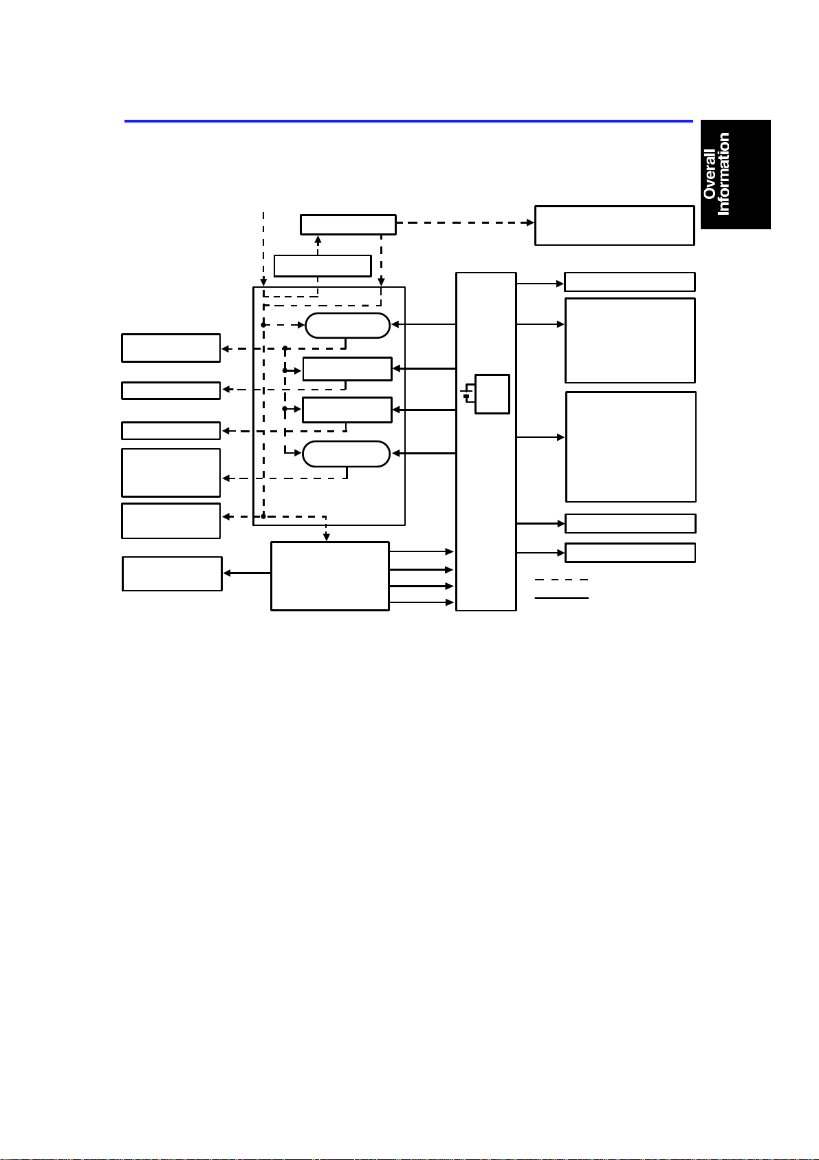
8. POWER DISTRIBUTION
AC Power (115V or 220~230V/240V)
Exhaust Blower
Motor (L)
Fusing Lamp
Exposure Lamp
Main Motor
Quenching Lamp
Exhaust Blower
Motor (H)
Document Feeder
(Option)
Drum Motor Board
(Drum Motor)
24V (VA)
Main SW
Cover Safety SW
Power Relay
(RA401)
Fusing Lamp
Drive Circuit
Exposure Lamp
Drive Circuit
Main Motor
Relay (RA402)
AC Drive Board
DC Power
Supply Board
24V (VA)
24V (VA)
24V (VA)
24V (VA)
30V (VM)
24V (VA)
5V (VC)
Zero Cross
RAM
Pack
Main
Board
Anti-condensation Heaters
-Drum (Option)
-Optics (Option)
9V
Scan
Signal
5V (VC)
24V (VA)
30V (VM)
9V (VB)
Operation Panel Board
Sensors
Switches
Drum Motor Board
(Encoder)
DF Interface Board
(A077/A078 copiers only)
Thermistors
Solenoids
Clutches
Power Packs
Lens Motor
(A077/A078 copiers only)
4th/5th Mirror Motor
(A078 copier only)
Optics Cooling Fan
Motors
Image Density Sensor
Scanner Motor
AC power
DC power
When this copier is plugged in and the main switch is turned off , ac power is
supplied via the ac drive board to the anti-condensation heate rs. Whe n the
front cover and/or the exit cove r is open, the cover safety switch complete ly
cuts off power to all ac and dc components. The RAM pack has a back up
power supply (dc battery) for the service program mode data and misfee d job
recovery.
When the main switch is turned on, the ac power sup ply to the
anti-condensation heat er is cut of f an d ac power is supp lied to the ac drive
board. The dc power supply board receives wall outlet ac power through the
ac drive board.
The dc power supply board converts th e wall outle t ac po wer inp ut to +5
volts, +24 volts, +30 volts and a zero cro ss signal.
1-15
Page 19

POWER DISTRIBUTION 15 January 1992
The +24 volts is supplied to both the main board and the drum motor board.
The +5 volts, +30 volts and th e zero cross sig na l are sup plied to the main
board.
The main board supplies dc p owe r to all copier dc components except for th e
drum motor. All sensors (except for the ID sensor), switches, thermisto rs, th e
drum motor encoder, plus the DF interface board operate on +5 volts. The
image density sensor as well as the operatio n pane l operates on +9 volts,
supplied by the main board. The scann er mot or op era te s on +30 volts. All
other dc components including the power relay (RA401) and th e main motor
relay (RA402) operate on +2 4 volt s. The document feeder has a separate dc
power supply.
When the main board receives power, it act ivat es the power rela y (RA 401)
which then supplies ac power to the fusin g lamp drive circuit, and the
exposure lamp drive circuit on the ac drive board. The exhaust blower motor
begins rotating at low speed. The fusing lamp drive circuit receives a trigger
signal from the main board an d the fusing lamp lights. The exp osure lamp
does not turn on until the main boa rd send a trigger pulse to the exp osu re
lamp drive circuit.
When the Start key is pressed, the main bo ard ene rgize s the main mot or
relay (RA402). Then, the main motor and the quenching lamp turn on an d th e
exhaust blower starts rotating at high speed.
When the main switch is turned off, power is cut off to the main board and to
RA401, and the optional drum and optics anti-condensation heaters are
turned on.
1-16
Page 20

SECTION 2
DETAILED SECTION
DESCRIPTIONS
Page 21

15 January 1992 DRUM
1. DRUM
1.1 DRUM CHARACTERISTICS
The drum has the characteristics o f:
1. Being able to accept a high negative electrical charge in the dark. (Th e
electrical resistance of a photocon ductor is high in the absence of light.)
2. Dissipating the electrical charge when exposed to light. (Exposure to light
greatly increases the conduct ivity of a photo con du cto r.)
3. Dissipating an amount of charge in dire ct pro po rtio n to the inte nsity of the
light. That is, where stronger light is directed to the photoconductor
surface, a smaller voltage remains on the drum.
4. Under low temperatures, drum photose nsit ivity dro ps an d residua l volta ge
increases. This makes it necessary t o monitor the drum temperature and
some compensation is require d.
5. During the drum’s life, drum residu al volt ag e gra du ally increases and the
photoconductive surface becomes worn.
Therefore, some compen sat ion for these characteristics is required.
2-1
Page 22
DRUM 15 January 1992
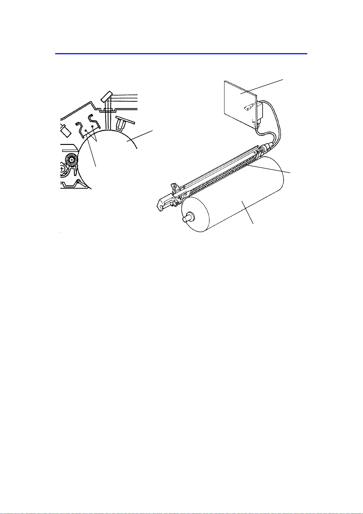
1.2 DRUM UNIT
[F]
[E]
[B]
[G]
[A]
[C]
[D]
An organic photoconductor (OPC) dru m [A] is used in this mode l.
A drum unit [B] holds the drum and preve nts stress on the drum. The drum
unit consists of an OPC drum, ID sensor bo ard [C] an d pick-o ff pawls [D] .
When the drum, the pick-off pawls, or the ID sensor is replaced or clean ed,
the drum unit must be removed from the copier.
The drum is driven by an independent drum motor [E] thro ugh a timing belt
[F] and the drum drive pulley [G].
The pick-off pawls are always in contact with the drum surface.
The ID sensor board consists of the ID sen sor and th e dru m the rmisto r.
2-2
Page 23
Drum Motor
(M7)
15 January 1992 DRUM
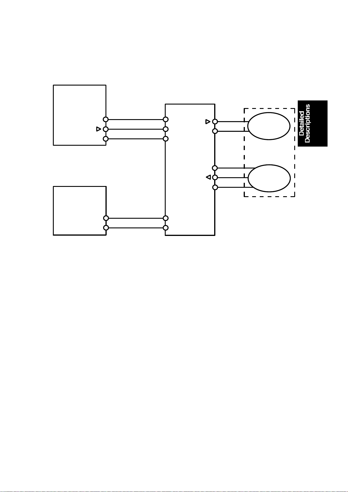
1.3 DRUM MOTOR CONTROL
Main Board
(PCB 1)
VC [5]
ON signal [▼5]
GND [0]
DC Power
Supply Board
(PCB 1)
VA [24]
GND [0]
CN131-3
CN131-2
CN131-1
CN204-3
CN204-1
CN801-1
CN801-2
CN801-3
CN802-3
CN802-1
▼24]
[
24 V
5 V
IN
GND [0]
Drum Motor
Board
(PCB 1)
CN803-1
CN803-2
CN804-3
CN804-2
CN804-1
Encoder
The drum motor is a dc servomotor. The drum motor board controls the
speed of this servomotor.
When the Start key is pressed, the main bo ard send s an "ON sig nal" to the
drum motor board (CN131-2) to energize the drum motor.
The encoder on the servomotor has a phot oin te rrupter that generates a
series of pulse signals. The drum mot or board monitors these pulse signals
to regulate the motor speed (10 0 mm/se con d).
2-3
Page 24
DRUM CHARGE 15 January 1992
2. DRUM CHARGE
2.1 OVERVIEW
[A]
[A]
[B]
[D]
[A]
This copier uses a double wire scorotro n and a highly sensitive OPC drum
[A]. The corona wires [B] ge ne rat e a corona of negative ions when the
CC/Grid/Bias power pack [C] applies a high voltage. The CC/Grid/Bias power
pack also applies a negative high volta ge to a stainless steel grid plate [D].
This insures that the drum coating receives a uniform negative charg e as it
rotates pa st the corona unit.
[C]
[D]
The exhaust fan, located abo ve the cop y exit, causes a flow of air from the
upper area of the deve lop ment unit through the charg e coro na unit . This
prevents an uneven bu ild-u p of negative ions that can cause uneven image
density. The exhaust fan runs at half spe ed when in the st and-by condition
and at full speed while copying.
The exhaust fan has an ozo ne filte r (a ctive ca rbo n) which adsorbs ozone (O3)
generated by the coro na charge. The ozone filter decre ases in efficiency over
time as it adsorbs ozone. The ozone filter should be replaced at every 80000
copies.
The flow of air around the charge corona wires may deposit paper dust or
toner particles on the corona wire . The se pa rticle s may interfere with
charging and cause low density ba nd s on cop ies. The wire clea ne r clean s
the corona wire when the op era to r slides the corona unit out and in.
2-4
Page 25
15 January 1992 DRUM CHARGE
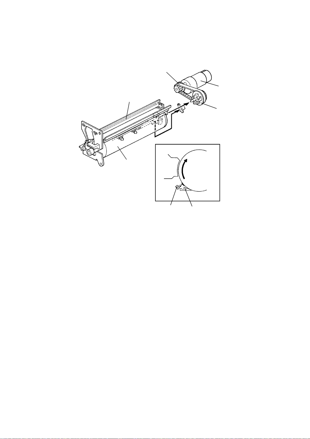
2.2 CHARGE CORONA WIRE CLEANE R MECHANI S M
[B]
[A]
[D]
[C]
Pads [A] above and below th e charge corona wires clean the wires as th e
charge unit is manually slid in and out.
The cleaner pad bracket [B ] rotates when the charge unit is fully e xte nd ed
and the bracket is pulled up against the rear en dblock [C]. This moves the
pads against the corona wires (see illustra tion). If the charge unit is not fu lly
extended, the pads do not tou ch th e corona wires.
The pads move away from the wires when the charg e unit is f ully inse rted
and the cleaning bracket is pushed against the front endblock [D].
After copier installa tio n the key operator should be instru cted to use this
mechanism when copies exhibit low ima ge den sity band s.
2-5
Page 26
Power Pack CC/Grid/Bias
(P1)
Charge Corona
Development
Bias
DRUM CHARGE 15 January 1992
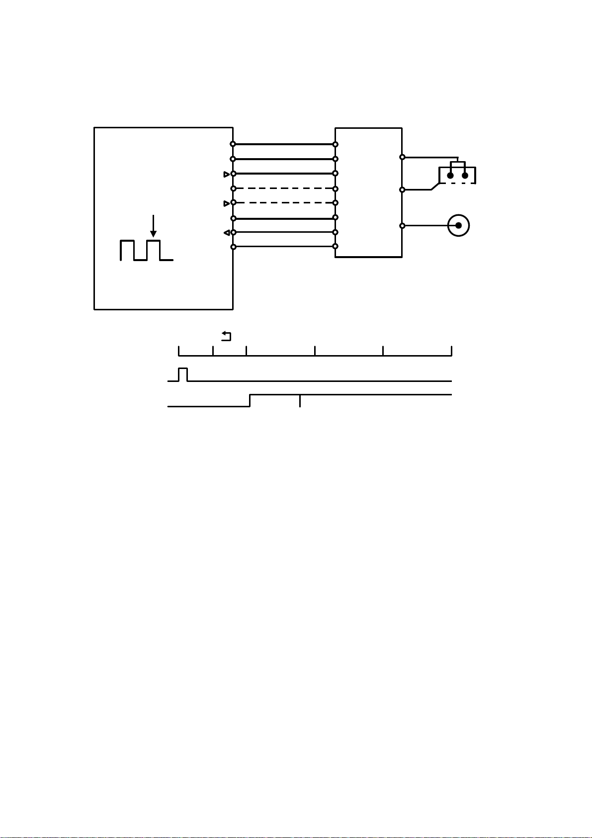
2.3 CHARGE CORONA CIRCUIT
VA [24]
VC [5]
CC Trig [▼24]
Grid Trig (PWM) [▲0→0/5]
Grid FB
GND [0]
Main Board (PCB 1)
1350
0
Timing Pulse
(1pulse=4msec)
Start Key
Charge Corona
and Grid Voltage
200
CN119-8
CN119-7
CN119-6
CN119-5
CN119-4
CN119-3
CN119-2
CN119-1
1500
1589 1782
Toner Density
Detection Cycle
CN1-1
CN1-2
CN1-3
CN1-4
CN1-5
CN1-6
CN1-7
CN1-8
2000 2500 3000
Image Area
M
G
B
Grid
(Pulse)
The main board supplies +24 volt s to th e CC/G rid/Bias power pack at CN1-1
as the power supply source. About 2.5 seconds after th e Start key is pressed
(during the toner d en sity detection cycle about 1.8 second s), th e CPU drops
CN1-3 from +24 volts to 0 volts. This energizes the charge coron a circuit
within the CC/Grid/Bias power pack, which applies a high nega tive volta ge of
approximately –7.0 K volts to th e cha rge corona wires. The corona wires then
generate a negative corona charge.
The grid plate limits the cha rge voltage to ensure that the charge does not
fluctuate and that an even charge is applied to the drum surfa ce.
The grid trigger pulse applied to CN1-5 is a pulse width modulated signal
(PWM signal). This signal is not only a trigger signal, it also chan ges the
voltage level of the grid. As the width of the pulse ap plie d incre ases, the
voltage of the grid also incre ases. The CPU monitors the grid volta ge at
CN119-2 and controls the width of the grid trigger pulses based on th is
feedback.
2-6
Page 27

15 January 1992 DRUM CHARGE
2.4 GRID VOLTAGE CORRECTION
To maintain good copy quality ove r the drum’s life , th e grid volta ge is
changed by the following:
• Drum residual voltage correction (Vr correction)
• Drum temperature correction
• Drum wear correction
2.4.1 Drum Resi dual Volta ge Corr ec tion (Vr corr ection)
During the drum’s life, the dru m may fat igu e electrically and residual voltage
(Vr) on the drum may gradually increase. When this happens, the corona
charged voltage on th e dru m is not disch arged enough in the quenching an d
exposure processes. Even if the development bia s is applie d in th e
development process, the background area of th e orig inal on the drum may
attract some toner. This may cause dirty background on copies. The Vr
correction prevents this ph enomenon as follows:
A pattern (Vr pattern) is develope d on the drum eve ry 100 0 cop ies and its
reflectivity is detected by the ID sen sor to measu re th e resid ua l volta ge . This
is called residual voltage detect ion . (If the reflectivity is low, the residual
voltage will be high.) When the Vr pattern is developed, all blocks of the
erase lamp turn on, and th e de velo pment bias voltage is 0 volt.
The CPU determines what level of Vr co rrect ion is necessa ry dep en din g on
the output (Vr ratio [L]) from the ID sensor.
Vrp
L =
x 100 (%)
Vsg
Vrp: ID sensor outp ut for Vr pattern
Vsg: ID sensor output for bare drum
The current Vr ratio is disp laye d by SP67.
The CPU increases the development bias voltage depending on the Vr ratio
to prevent dirty backgrou nd on copies, (See page 2-33 for more informatio n. )
The CPU also increases the grid volta ge to ensure prop er imag e de nsit y
depending on the Vr ratio. (See page 2-11.)
Because the grid voltag e is increased, the charge volta ge on th e dru m ’s
surface is also increased. To compe nsate for the charge voltage increase,
the exposure lamp voltage is also incre ased. (See page 2-21.)
2-7
Page 28

DRUM CHARGE 15 January 1992
2.4.2 Drum Temperature Correction
During a low drum temperature condition, the drum’s residual voltage
increases and drum photosen sitivity drops due to the characterist ics of th e
drum. This may cause dirty background on copies.
A drum temperature correct ion is made to compe nsa te for th is phe nomenon
as follows:
A drum thermistor on the ID sensor board mon itors the temperature around
the drum. When the drum temperature is less than 20°C, the CPU increases
the development bia s vo lta ge to pre vent dirty background on copies. (S ee
page 2-33.) The CPU also increases th e grid voltage to ensure proper image
density. (See page 2-11.) The exp osu re lamp voltage is also increased to
compensate for the drum p hoto sensitivity drop. (See page 2-20.) Whe n the
drum temperature is 20°C or higher, the drum te mpe rat ure correct ion is not
made.
2.4.3 Drum Wear Correction
During the drum’s life, the photoco nd uct ive surf ace of the drum becomes
worn by contact with the cleaning brush. This effects ability of the drum to
hold a charge. This characte ristic esp ecially affects developing of th e ID
sensor pattern. The ID sensor pattern developed on th e dru m b eco mes
lighter causing high er to ne r co nce ntration in the developer. The drum wear
correction is made to prevent this phenomenon and is as follows:
The CPU keeps track of the drum motor ro ta tio n time that corre sponds to the
wear of the photoconductive layer. The grid voltage for the toner density
detection increases at set int erval. The grid voltage for the residu al volt ag e
(Vr) detection also increase s at th e same interval. (See page 2-12.) The dru m
motor rotation time is displayed by SP57.
2-8
Page 29

15 January 1992 DRUM CHARGE
2.5 GRID VOLTAGE FOR IMAGE DENSITY CONTROL
The main board controls the grid volt age fo r a copy imag e th rou gh the
CC/Grid/Bias power pack. As the grid volta ge beco mes less, the copy imag e
becomes lighter and vice versa. The grid voltage is based on the stand ard
image grid voltage (Vg) and various correction fact ors.
The method of control is different dependin g on whethe r the ima ge density is
manually selected, or the auto imag e de nsit y mode is used.
The grid voltage for non-image areas (betwee n cop ies) is 0 volt (Fixed ).
The grid voltage while cop ying consists of the following facto rs:
1. Manual image density mode
Grid voltage = Standard image density grid voltage
(Vg = –680 volts [SP60=4])
+
Manual image density level factor
+
Drum residual voltage (Vr) correction factor
+
Drum temperature correction factor
2. Auto image density mode
Grid voltage = Standard image density grid voltage
(Vg = –680 volts [SP60=4])
+
Auto image density level fact or (SP 34 )
+
Drum residual voltage (Vr) correction factor
+
Drum temperature correction factor
2-9
Page 30

DRUM CHARGE 15 January 1992
2.5.1 Manua l Image Density Level Factor
Darker Lighter
Manual ID level 1 2 3 4 5 6 7
Change of grid voltage (volts) ±0 ±0 ±0 ±0 ±0 +50 +50
The grid voltage does not change for manual image density levels 1 through
5. However, the exposure lamp volt ag e an d th e de velo pme nt bias volt ag e
does vary depending on the manual imag e de nsit y le vel. (See page 2-1 9 and
2-31.)
The grid voltage at the manual image density level 6 is the same as the one
at level 7, however, the exp osure lamp voltage and the deve lop ment bias
voltage are different. (See page 2-19 and 2-31.)
2.5.2 Auto Ima ge Dens ity Level Factor (SP34)
Auto image density level Data (SP34) Change of grid voltage (volts)
Normal 0 ±0
Darker 1 –50
Lighter 2 ±0
The grid voltage and the expo sure la mp volt ag e are co nst an t reg ardless of
the output from the auto image de nsit y senso r. Only the development bias
voltage varies depending on the output from the auto image density sen sor.
When the auto image densit y le vel data is set to lighter, the chang e of the
grid voltage is 0 volt. However, th e de velo pme nt bias volt ag e is chan ged –4 0
volts.
2-10
Page 31

15 January 1992 DRUM CHARGE
2.5.3 Drum Residual Voltage (Vr) Correction Factor
Vr ratio (L) (%) (SP67) Change of grid voltage (volts)
100 to 84 ±0
83 to 58 –40
57 to 41 –80
40 to 28 –120
27 to 0 –160
L = Vrp/Vsg x 100 (%)
Vrp: ID sensor output for Vr pattern
Vsg: ID sensor output for bare drum
During the drum’s life, drum residu al volt ag e (Vr) may gra du ally incre ase. Vr
correction compensate s for th e resid ua l volta ge on the dru m. The Vr
correction is done every 1000 copies. The CP U increa ses the development
bias voltage, the grid volt age, and the exposure lamp voltag e. The ab ove
table shows how the grid volta ge chan ge s dep en din g on the Vr ra tio .
2.5.4 Drum Temperature Correction Factor
Drum Temperature Change of grid voltage (volts)
20°C or higher ±0
Lower than 20°C –40
2-11
Page 32

DRUM CHARGE 15 January 1992
2.6 GRID VOLTAGE FOR TONER DENSITY DETECTION AND
RESIDUAL VOLTAGE (Vr) DETECTION
2.6.1 Grid Vol tage for Toner Density Detection
Grid voltage = Standard ID sensor grid voltage (– 460 volt s [SP 62 =4] )
+
Drum wear correction factor (SP 57)
Drum Wear Correction Factor (SP57)
Drum motor rotation time (SP57) Change of grid voltage (volts)
0 to 2H ±0
2 to 65H –20
65 to 112H –40
112 to 157H –60
More than 157H –80
2.6.2 Grid Vol tage for Residual Voltage (Vr) Detection
Grid voltage = Standard ID sensor grid voltage (– 460 volt s [SP 62 =4] )
+
Drum wear correction factor
(SP57 [See the above table.])
The grid voltage for th e to ne r den s ity de te ction is the same as the one for the
residual voltage (Vr) detection, however, the development bias voltage is
different. (Se e page 2-33 and 2-39.)
2-12
Page 33

[E]
15 January 1992 OPTICS
3. OPTICS
3.1 OVERVIEW
[B]
[C]
[D]
During the copy cycle, an image of the original is reflecte d onto the drum
surface through the optics assembly as follows.
Light Path:
Exposure Lamp [A] → Original → First Mirror [B] → Second Mirror [C]
→ Third Mirror [D] → Lens [E] → Fourth Mirror [F]→ Fifth Mirror [G]
→ Sixth Mirror [H] → Drum [I]
[A]
[H] [ F] [J]
[I]
[G]
The optics cooling fan [J] draws cool air into the optics cavit y. The air flows
from the right to the left in the optics ca vity and exh au sts th rou gh the vent s in
the left side of the upp er cove r. This fan operates during the copy cycle.
This copier has six standard reproduction ratios (A077/A078 copiers only),
three reduction ratios, two enlargement ratios, and full size. It also has a
zoom function. The ope rat or can change the reproductio n rat io in on e
percent steps from 61% to 141%.
Stepper motors are used to cha nge th e positio ns of the lens and mirrors
(A077/A078 copiers only). Separate motors are used because the wide rang e
of reproduction ratio s makes it mechanically difficult for one moto r to position
both the lens and mirrors. A ste pp er motor is also used to drive the scanne r.
This motor changes the scanner spe ed accord ing to th e rep rod uction ratio.
The thermofuse open s at 12 6°C and removes ac power to the exposure lamp
to prevent overheating.
2-13
Page 34

OPTICS 15 January 1992
3.2 SCANNER DRIVE
[B]
[D]
[E]
[F]
[C]
[A]
[G]
3.2.1 1st and 2nd Scanner Drive Mechanism
This model uses a stepper mot or [A ] to drive the scanners. Both ends o f each
scanner are driven to prevent skewin g. The scanners have sliders [B], wh ich
ride on guide rails.
The scanner home position is detected by the home positio n sensor [C]. The
scanner return position is determine d by cou nt ing the scanner motor drive
pulses.
The first scanner [D], which consist s of the exp osure lamp and the first mirror,
is connected to the scanner drive wire by the wire clamps [E]. The second
scanner [F], which consists of th e seco nd and third mirro rs, is conn ect ed to
the scanner drive wire by movable pulleys (th e second scanner pulleys [G]).
The pulleys move the second scanne r at half the velocity of the first scanner.
This maintains the focal distance between the original and the lens during
scanning. This relationship can be expressed as:
V1r = 2 (V2r) = VD/r
where r = Reproduction ratio
V1r = First scanner velocity (when the reproduct ion ratio
is "r")
V2r = Second scanner velocity (when the reprod uction ratio
is "r")
VD = Drum peripheral velocity (100 mm/s)
2-14
Page 35

: Reduction
: Enlargement
15 January 1992 OPTICS
3.3 LENS DRIVE (A077/A078 copiers only)
[C]
[D]
[B]
[F]
[E]
[A]
[G]
3.3.1 Lens Drive
The lens motor [A] (stepper motor) changes the lens [B] position through the
lens drive wire [C] in accordance with the selected reproduction ratio to
provide the proper optical distan ce between the lens and the drum surface.
The rotation of th e len s drive pu lley moves the lens back and forth in discrete
steps. The home position of th e lens is dete cte d by th e home position sensor
[D]. The main board keeps track of the lens position base d on the numb er of
pulses sent to the lens mo to r.
3.3.2 Sha ding Mechanism
The shading plate s [E] are installed on the lens housin g [F] and are slid op en
and shut by the groove cams [G]. When the lens move s in the redu ctio n
direction, the groove cams mo ve th e shading plates closer together. The
plate blocks part of the light passing through the lens to keep the intensity of
the light on the drum even.
2-15
Page 36

OPTICS 15 January 1992
3.3.3 Lens Positioning
[C]
[A]
Home Position (100%)
[B]
(100% → 141/129%)
[D]
(141/129% → 71/65%)
(71/65% → 93%)
(93% → 71/65%)
(71/65% → 141/129%)
(141/129% → 122/121%)
(122/121% → 141/129%)
(122/121% → 100%)
(100% → 71/65%)
(71/65% → 100%)
Reduction SideEnlargement Side
The lens home position sensor [A] informs the main board when the lens is at
full size position (home position). The main board de termine s the lens sto p
position in reduction and enlargement modes by counting the number of
steps the motor makes with refe rence to the lens home position. When a new
reproduction ratio is select ed , th e lens [B] moves directly to the selected
magnification position.
The lens home position is registe red each time the lens starts from or passes
through the lens home position sensor. As the len s mo ves fro m t he
enlargement side to th e red uction side, the sensor regist ers the home
position. This occurs when the actu at or plate [C] enters the lens home
position sensor.
A small vibration can be observed when the lens moves through home
position from the red uct ion side to the enlargement side because the lens is
going in the wrong dire ctio n to register the home position. The lens
overshoots the home position by on ly one pulse before going back to register
the home position.
The lens always stops while moving from lef t to rig ht (as viewed from the
front) to minimize the error ca use d by mech an ical pla y in the drive gears [D].
2-16
Page 37

(71/65% → 100%)
15 January 1992 OPTICS
3.4 4TH/5TH MIRROR DRIVE (A077/A078 copiers only)
[B]
[A]
Home Position (100%)
(100% → 141/129%)
(141/129% → 71/65%)
(71/65% → 93%)
(93% → 71/65%)
(71/65% → 141/129%)
(141/129% → 122/121%)
(122/121% → 141/129%)
(122/121% → 100%)
(100% → 71/65%)
3.4.1 Drive
The 4th/5th mirror drive motor (stepper motor) changes the 4th/5th mirror
assembly position through the pinion gears [A] and the rack gear [B] in
accordance with the selected reprodu ctio n ratio to provid e the prope r optical
distance between the lens and drum surf ace .
3.4.2 Positioning
The positioning mechanism is similar to that of lens po sitio ning, as shown in
the above positioning chart. The 4th/5th mirror assembly always st ops wh ile
moving from right to left (a s viewed from th e front).
2-17
Page 38

70 mm
a
Sampled area
b
OPTICS 15 January 1992
3.5 AUTOMATIC IMAGE DENSITY SENSING
[C]
[B]
[A]
Light from the exposure lamp is refle cted from the original and travels to the
lens [A] via the mirrors. The auto ID senso r [B] , a phot od iod e, is mount ed on
the upper front frame. The senso r cover [C] has a hole in it to allow light to
fall directly onto the sensor. Sampling starts 10 millimete rs from th e leadin g
edge of the original and continues for 40 millimeters from the leadin g edge of
original in full size mode. The length of "a" and "b" will vary depending on the
selected reproductio n ratio (A077/A078 copiers only).
The lengths "a" and "b" in each reproduction ratio are calcu lated as follows:
a =
10 mm
Reproduction Ratio (%)
x 100 b =
Reproduction Ratio (%)
40 mm
x 100
The photosensor circuit converts the light intensity to a voltage. The dete cte d
voltage is amplified and sent to the main PCB. The CPU stores the voltage of
each sampled point in RA M. It the n comp utes the image density of the
original from the maximum sample volt ag e an d cha ng es th e de velo pme nt
bias accordingly. (See page 2-3 1 for d eta ils. ) The exposure lamp voltage is
constant regardless of the image density of the origin al.
2-18
Page 39

15 January 1992 OPTICS
3.6 EXPOSURE LAMP VOLTAGE CONTROL
The main board controls t he expo sure la mp volt ag e th rough the ac drive
board. The exposure lamp voltage is based on the base lamp volta ge and
various correction factors.
The exposure lamp voltage consist s of th e followin g fo ur fa cto rs:
Exposure lamp voltage = Base exposure lamp voltage factor
(Manual or auto image density mode)
+
Reproduction ratio correction factor
(A077/A078 copiers only)
+
Drum temperature correction factor
+
Drum residual voltage (Vr) correction factor
3.6.1 Bas e Lam p Voltage Factor In Manual Image Density Mode
Manual ID Level
Exposure Lamp Data
Darker Lighter
123456 7
Vo –4 Vo –4 Vo –2 Vo ±0 Vo+2 Vo+2 Vo+4
The above table shows chan ge s in the expo sure lamp data in the manual
image density mode.
SP48 sets the exposure lamp data for level 4 (Vo) of manual image density
mode. A value from 100 to 15 0 can be sele cted.
3.6.2 Bas e Lamp Voltage Factor In Auto Image Density Mode
In the auto ID mode, the CPU selects the level 4 (Vo) exposure lamp data
(SP48) regardless of the inpu t fro m the auto imag e de nsit y senso r.
2-19
Page 40

OPTICS 15 January 1992
3.6.3 Reproduction Ratio Correction Factor (A077/A078 copiers only)
Reproduction ratio (%) Change of exposure lamp data
61 to 62 –2
63 to 119 ±0
120 to 129 +2
130 to 141 +4
The exposure lamp data is in crea sed or decreased depending on th e
selected magnificatio n ratio in order to compensate for the chang e in the
concentration of ligh t on the drum.
3.6.4 Drum Temperature Correction Factor
Drum temperature Change of exposure lamp data
20°C or higher ±0
Lower than 20°C +2
The exposure lamp data is in crea sed to compensate for the drum
photosensitivity drop under low te mperature.
If the temperature is lower than 20°C when the main switch is turned on, the
CPU increases the exposu re lamp data by +2 as shown in the above tab le.
When the temperature go es to 20°C or higher, this correction is cancele d.
2-20
Page 41

15 January 1992 OPTICS
3.6.5 Drum Residual Voltage (Vr) Correction Factor
During the drum’s life, drum residu al volt ag e (Vr) may gra du ally incre ase. Vr
correction compensate s for th e resid ua l volta ge on the dru m. The Vr
correction is done every 1,000 copies. Depe nd ing on the Vr rat io (SP 67 ), th e
CPU increases the develo pme nt bias voltage, the grid voltage an d the
exposure lamp voltage. The following table shows ho w the lamp da ta
changes depending on the Vr ratio.
Vr ratio (L) (%) (SP67) Change of exposure lamp data
100 to 84 ±0
83 to 58 +2
57 to 41 +4
40 to 28 +6
27 to 0 +8
L = Vrp/Vsg x 100 (%)
Vrp: ID sensor output for Vr pattern
Vsg: ID sensor output for bare drum
2-21
Page 42

OPTICS 15 January 1992
3.7 EXPOSURE LAMP CONTROL CIRCUIT
Main Board (PCB1)
AC Drive Board (PCB2)
CN107-1
B
Zero
Cross
CPU
TP111
(EXPO)
E
Feed back
signal
0V
+24V
C
24V
0V
Trigger Pulse
AC power
Zero cross
Trigger pulse
Lamp power
CN114-2
CN114-1
CN114-7
CN114-3
CN401-7
CN401-8
CN401-2
CN401-6
ZD
ZD
401
R404
R405
VR401
C401
R403
R401
PC401
A
B
C
D
402
ZD
403ZD404
D401
R406
R411
TRC401
R413
DB401
CR401
L401
L402
CN421
240V
220V
220V Only
TR401
C411
T402
CN419-1
Thermofuse (TF)
Exposure
Lamp
(L1)
D
CN419-2
T407
A
AC115V
AC220V
AC240V
Feedback
signal
E
Feedback
The main board sends lamp trigg er (LO W sig nal) p ulse s to th e ac drive boa rd
from CN114-3. PC401 activates TRC401, which provides ac power to the
exposure lamp, at the lead edge of each trigger pulse.
The voltage applied to the expo sure lamp is also provided to the fee db ack
circuit. The feedback circuit steps down (TR401), rectif ies (DB401), and
smoothes (sensor diodes and cap acitors) the lamp voltage. The CPU
monitors the lowest point of th e smoo thed wave (feedback signal), which is
directly proportional to the actu al lamp volta ge .
The CPU changes the timing of the trigger pulses in response to the
feedback voltage. If the lamp voltage is too low, the CPU sends the trigg er
pulses earlier so that more ac power is applie d to the expo sure lamp. This
feedback control is performed instantly; so, the lamp voltage is always stable
even under fluctuating ac power conditions.
The voltage applied to the expo sure lamp can be changed with SP48 (Light
Intensity Adjustment). The ADS volta ge adju stme nt (S P56) must be done
whenever the light intensity adjustment is done.
2-22
Page 43

15 January 1992 OPTICS
3.8 OPTICS COMPONENT CONTROL TIMING
1350
Timing Pulse
(1pulse=4msec)
200
0
1500
2000 2500 3000
(Pulse)
Start Key
Scanner Motor
Exposure Lamp
Auto Image
Density Sensing
1587
Toner Density
Detection Cycles
1787 2767
1678
Image Area
1892 1986
B4 scan
Reproduction ratio 100%
The exposure lamp turn s on ab ou t 2. 1 seconds (on toner density dete ctio n
cycles about 1.7 seconds) and the scanner motor energizes about 2.5
seconds for the forwa rd scan after the Start key is pressed.
About 6.5 seconds af te r (B 4 scan ) t he Sta r t key is pressed, the exposure
lamp turns off and the scanner motor de-energize s and reverses for the
returns scan.
In the auto image density mode, the aut o image de nsit y senso r se nse s the
original background density between about 3 seconds a nd 3.3 seconds after
the Start key is pressed.
2-23
Page 44

[A]
LE
EL
ERASE 15 January 1992
4. ERASE
4.1 OVERVIEW
[B]
SE
ES
LO
LC
LE: Lead edge erase margin 2.5 ±1.5 mm
SE: Side erase margin 2.0 ±2.0 mm on each side;
total of both sides 4 mm or less
LO: Original width
LC: Charged width of drum
EL: Lead edge erase
ES: Side erase
The erase lamp [A] consists of a sing le row of LEDs (29 LEDs) ext en din g
across the full width of th e dru m [B] .
The erase lamp has three functio ns: lead edge era se, side erase, and trail
edge erase. Trail edge erase begins after the trailing edge of the copy paper;
therefore, the trailing edge of the copy will not be era sed .
2-24
Page 45

15 January 1992 ERASE
abcde
h
g
fc
abde
4.1.1 Lead Edge Erase
The entire line of LEDs turn on when the main mot or tu rns on . The y stay on
until the erase margin slight ly overla ps the lead edge of the original image
area on the drum (Lead Ed ge Erase Ma rgin ). This prevents the toner density
sensor pattern fro m being developed every copy cycle and th e shadow of the
original edge from being deve loped on the paper. At this point , side erase
starts. The width of th e lead edge erase margin can be adjusted using SP41.
During the toner density detection cycle (once every ten copy cycles), a block
of erase lamps (labeled "g" above) turns off long enough for th e sensor
pattern to be developed.
The entire line of LEDs turn on when the re sidu al volt ag e on the OPC dru m is
being detected (Vr detectio n).
4.1.2 Side Erase
This machine has no sensors or switches to detect the copy paper size.
Instead, the CPU measures the copy paper lengt h usin g the registration
sensor during the first copy cycle. Base d on this len gt h data , th e CPU
determines which copy paper size is used in the paper tray. (See page 2-5 7
for more information.)
The LEDs turn on in blocks as labeled "a" – "h" above.
2-25
Page 46

ERASE 15 January 1992
In the full size copy mode, the CPU determines which blocks turn on base d
on the copy paper len gt h da ta as follows:
Paper length Paper size Blocks ON
364 mm and 356 mm B4, 10" x 14", 8
1/2" x 13", 81/4" x 13" (F4), 8" x 13", 81/2" x
330 mm and 279 mm
297 mm, 267 mm, and 254 mm A4R, 8" x 10
257 mm, 216 mm, and 210 mm B5R, 5
For toner density detection cycles. a – f, h
For residual voltage (Vr) detection cycles. All
8
11"
1/2" x 81/2", A5R a – e
1/2" x 14", 81/4" x 14" None
a – b
1/2", 8" x 10" a – c
NOTE: Since the CPU cannot distinguish the differe nt paper width, the CPU
will determine the size to be the larger standard width based on the
measured length.
(EX: 10" x 14", 81/2" x 14" → The CPU recognizes as 10" x 14".)
In the reduction or enlarge ment copy mode (A077/A078 copiers only), the
CPU determines which blocks turn on base d on the selected reproduction
ratio as follows:
Reproduction ratio (%)
(A077/A078 copiers only)
83 – 99, 101 – 141 None
78 – 82 a
73 – 77 a – b
68 – 72 a – c
64 – 67 a – d
61 – 63 a – e
Blocks ON
4.1.3 Tra iling Edge Erase
The entire line of LEDs turns on after the trailing edge of the latent image has
passed. Therefore, a trailing erase margin cannot be observed on the copy.
The LEDs stay on to erase th e leading edge of the lat en t image in the next
copy cycle. After the fin al copy, the erase lamps turn off at th e same time as
the main motor.
2-26
Page 47

[F]
[D]
15 January 1992 DEVELOPMENT
5. DEVELOPMENT
5.1 OVERVIEW
[E]
[B]
[C]
[A]
When the main motor turns on , an d th e de velopment clutch solenoid is
de-energized, the paddle roller [A ], development roller [B], auge r [C], and the
agitator [D] start turn ing . The paddle roller picks up developer in its paddles
and transports it to the develop ment roller. Internal permanent magn et s in the
development roller att ract the deve lop er to the deve lop men t rolle r sle eve .
The turning sleeve of the deve lopment roller then carries the deve loper past
the doctor blade [E]. The doct or blade trims the developer to the desired
thickness and creates a developer backspill to the cross-mixing mechanism.
The development roller con tin ue s to tu rn, carrying the deve lop er to the OPC
drum. When the developer bru sh con ta cts th e dru m surface, the negatively
charged areas of the drum surfa ce at tra ct an d hold th e positive ly ch arg ed
toner. In this way, the latent image is developed.
The development roller is given a negat ive bia s to pre ven t toner from being
attracted to the non-image areas on the drum which may have a resid ual
negative charge. The bias also cont rols image density.
After turning abou t 10 0 de gre es more, the development roller rele ases the
developer to the deve lopment unit. The develope r is agita ted by the paddle
roller, agitator, and the cross-mixing mechanism.
The developer is installed in the machine in advance. Whe n installing the
machine, you must load the deve lop er into the development unit from th e
developer tank [F] by pulling out the sea l. Then, use SP65 to agitate the
developer.
2-27
Page 48

DEVELOPMENT 15 January 1992
5.2 DRIVE MECHANISM
[G]
[E]
[B]
[A]
[H]
[C]
[D]
[F]
[J]
[I]
[M]
[K]
[L]
When the main motor [A] turns, the rota tio n is tran smitt ed from th e
development drive gea r [ B] to th e de velopment roller gear [C] thro ug h th e
development clutch [D] , timin g be lt [E ] an d relay gea rs. (The ro tation is
transmitted to the de velo pment drive gear when the develo pme nt clu tch
solenoid [F] is de-energize d. ) Then , th e rot ation is transmitted from the
development roller gear to the paddle rolle r gear [ G] throug h the idler g ear [H].
A gear [I] on the front end of the paddle roller shaft drives the auger gear [J]
and the agitator gear [K]. The padd le rolle r shaf t ha s a knob [L] on the fro nt
end so that it can be turned man ua lly t o exch an ge toner. The knob has a
spring clutch [M] inside. The sprin g clut ch prevents the development roller
from being turned in the wrong direction.
The development clutch solenoid energizes aft er imag e de velopment during
the last copy cycle is completed. This sto ps th e rolle rs, thereby reducing
developer fatig ue.
2-28
Page 49

15 January 1992 DEVELOPMENT
5.3 CROSS-MIXING
[E]
[A]
[D]
[B]
[C]
[F]
This copier uses a standard cross-mixing mechanism to keep the toner and
developer evenly mixed . It also he lps ag ita te the developer to prevent
developer clumps from forming and help s create the trib oelectric charge.
The developer on the tu rning development roller is split int o two parts by the
doctor blade [A]. The deve loper that stays on the develop ment roller [B]
forms the magnetic brush an d de velo ps the latent image on the drum. The
remaining developer th at is trimmed off by th e doctor blade goes to the
backspill plate [C].
As the developer slides down the backspill plate to the agit ator [D], the mixing
vanes [E] move it slightly to ward the rear of the unit. Part of the developer
falls into the auger inlet and is transp ort ed to the fro nt of the unit by th e auge r
[F].
2-29
Page 50

DEVELOPMENT 15 January 1992
5.4 DEVELOPMENT BIAS FOR IMAGE DENSITY CONTROL
Image density is controlled by changing three items: (1) the amount of bias
voltage applied to th e de velo pment roller sleeve, (2) the amou nt of voltage
applied to the exposure lamp, an d (3) the amo un t of voltage applied to the
grid plate.
Applying a bias voltage to the development sleeve reduce s the pot en tia l
between the develo pment roller and the drum, thereby reducing the amount
of toner transferred. As the bias voltage beco mes gre at e r, the copy image
becomes lighter and vice versa.
The method of control is different dependin g on whethe r the ima ge density is
manually selected or the auto image density mode is used.
The development bias voltag e applied to the development roller sle eve has
the following four factors:
Developmen t bia s voltage = Base bias voltage factor
(Manual or auto image density mode)
+
Image bias voltage adjustment factor (SP37)
+
Drum residual voltage (Vr) correctio n factor
+
Drum temperature corre ctio n factor
The base bias voltage for non-image area s (bet wee n cop ies) is – 160 volt s.
The above correction factors are also applied.
2-30
Page 51

15 January 1992 DEVELOPMENT
5.4.1 Bas e Bias Voltage Factor In Manual Image Dens ity Mode
Manual ID Level 123456 7
Base Bias Voltage (volts) –120 –160 –160 –160 –200 –200 –240 *Note
Exposure Lamp Data Vo –4 Vo –4 Vo –2 Vo ±0 Vo +2 Vo+2 Vo+4
Grid Voltage (volts) Vg ±0 Vg ±0 Vg ±0 Vg ±0 Vg ±0 Vg +50 Vg +50
Vo: Exposure Lamp Data for ID level 4 (SP48)
Vg: Standard Image Grid Voltage (–680 volts)
Darker Lighter
In manual ID mode, the base bia s voltage depends on the manually selected
ID level. The voltage applied at each ID level is shown in the abo ve ta ble.
The base exposure lamp vo lta ge and the grid voltage also vary depending on
the manual ID level as shown in the table.
*Note: The base bias voltage at ID level 7 can be cha ng ed using SP5 0 as
follows.
Image density Data (SP50) Bias voltage (volts)
Normal 0 –240
Darker 1 –200
Lighter 2 –280
Lightest 3 –320
(Factory Setting: –240 volts)
5.4.2 Bas e Bia s Vol tage Factor In Automatic Image Density Mode
In auto image density mode, the base expo sure lamp voltage is fixed to Vo
(SP48). Image density is con tro lled by chan gin g on ly the base bias volt age.
The base bias voltage depends on the background image density of the
original, which is measured using the auto ID sen sor. (See page 2-18 for
more information.)
The CPU checks the voltage output from the automa tic ID circuit . This circuit
has a peak hold function. The peak hold voltage corresponds to the
maximum reflectivity of the original. The CPU then determines the proper
base bias level with refere nce to th e pe ak ho ld voltage.
The table on the following page gives the base bia s voltages at each ADS
output level.
When the automatic density level is set to lighter by SP34, the base bias
voltage shifts –40 volts as shown in th e fo llowin g table.
2-31
Page 52

DEVELOPMENT 15 January 1992
K
K ≥ TL1
TL1 > K ≥ TL2
TL2 > K ≥ TL3
TL3 > K
K =
Normal or Darker (SP34 = 0 or 1) Lighter (SP34 = 2)
ADS Output Voltage (Peak Hold Voltage)
ADS Reference Voltage (SP56)
–160
–220
–280
–340
Base Bias Voltage (volts)
–200
–260
–320
–380
TL1 to TL3: Threshold le vel (Se e the following table.)
To maintain the correct image density, the exposure lamp data is
incremented when the repro duction ratio is changed or drum temperatu re
correction or drum residual voltage correct ion is done. This incre ment in the
lamp data increases the int en sity of light reflected from the original.
Therefore, the aut o ID sen sor ou tput voltage also changes. In ord er to
maintain a constant volt age for the same original when the lamp data is
incremented, the threshold levels are shifted up with each increment in the
lamp data as shown in the following table.
Increase of
exposure lamp data
TL1 0.70 0.75 0.80 0.85 0.89 0.94 0.98 1.03 1.08 1.12
TL2 0.66 0.70 0.74 0.78 0.83 0.87 0.91 0.96 1.00 1.04
TL3 0.29 0.31 0.33 0.35 0.37 0.39 0.41 0.43 0.45 0.48
+0 +1 +2 +3 +4 +5 +6 +7 +8 +9
5.4.3 Image Bias Voltage Adjustment Factor
Image Bias Adjustment (SP37)
Image density Data (SP37) Change of bias voltage (volts)
Normal 0 ±0
Darkest 1 +40
Darker 2 +20
Lighter 3 –20
Lightest 4 –40
The image bias voltage can be changed by SP 37 to adjust the image density
level. The above table gives the image bias volt ag e fo r SP mod e set ting. This
adjustment should be done only if the expo sure la mp volt ag e adjustment
(SP48) fails to achieve the desire d image density.
2-32
Page 53

15 January 1992 DEVELOPMENT
5.4.4 Drum Residual Voltage (Vr) Correction Factor
During the drum’s life, drum residual volt age (Vr) may gradually increase.
The Vr correction compensat es fo r t he re sidu al volt ag e on the drum. The Vr
correction is done every 1,000 copies. The fo llowin g table shows how the
development bias voltage changes depending on the Vr ratio.
Vr ratio (L) (%) (SP67) Change of bias voltage (volts)
100 to 84 ±0
83 to 58 –40
57 to 41 –80
40 to 28 –120
27 to 0 –160
L = Vrp/Vsg x 100 (%)
Vrp: ID sensor output for Vr correction pattern
Vsg: ID sensor output for bare drum
When the Vr correction is made (eve ry 1,0 00 copies), all blocks of erase
lamps turn on and the development bias becomes 0 volt to develop the Vr
pattern.
5.4.5 Drum Temperature Correction Factor
Drum temperature Change of bias voltage (volts)
20°C or higher ±0
Lower than 20°C –40
To compensate for the drum p hoto sen sitivity drop under low temperature, th e
development bias vo lta ge is increased.
If the temperature is lower than 20°C when the main switch is turned on, the
CPU increases the develo pme nt bias voltage by –40 volts as shown in the
above table.
When the temperature go es to 20°C or higher, this correction is cancele d.
2-33
Page 54

Power Pack CC/Grid/Bias
(P1)
Charge Corona
DEVELOPMENT 15 January 1992
5.5 DEVELOP MENT BI AS CIRCUIT
VA [24]
VC [5]
Bias Trig (PWM) [▲0→0/5]
Bias FB
GND [0]
Main Board (PCB 1)
CN119-8
CN119-7
CN119-6
CN119-5
CN119-4
CN119-3
CN119-2
CN119-1
CN1-1
CN1-2
CN1-3
CN1-4
CN1-5
CN1-6
CN1-7
CN1-8
M
G
B
Grid
Development
Bias
The main board supplies +24 volt s to th e CC/G rid/Bias power pack at CN1-1.
When the Start key is pressed, the CPU starts sending the bias trigger pulses
to CN1-4. This energizes the develo pme nt bias circuit wit hin the
CC/Grid/Bias power pack, which applies a high negative volta ge to the
development roller. The deve lop ment bias is applied whenever the drum is
rotating except when the Vr patter n is developed.
The bias trigger pulse applied to CN1-4 is a pulse width modulated signa l
(PWM signal). The width of the pulses controls the volta ge level of the
development roller. As th e width of the trigger pulses increase, the voltage to
the development roller also increases. The CPU monitors the development
bias voltage at CN119-3 an d con trols the width of the bias trigg er pu lses
based on this feedback.
2-34
Page 55

15 January 1992 DEVELOPMENT
5.6 DEVELOP MENT CO MPO NENT CO NTROL TI MI NG
Timing Pulse
(1pulse=4msec)
Start Key
Main Motor
Development
Bias
Development
Clutch Solenoid
1350
0
200
1500
Non Image Area
1591
2000 2500 3000
1991
1857
Image Area
Toner Density Detection Cycles
When the Start key is pressed, the main motor starts rotating and the
development clutch sole no id is ene rgize d. At th is time, the rotation from the
main motor is not transmitted to the rolle rs in the deve lop men t un it. The
development clutch solenoid is de-energized abou t 1. 8 seconds after the
Start key is pressed. At this time, the ro llers in th e de velo pme nt unit start
rotating.
(Pulse)
When the Start key is pressed, the deve lopment bias circuit in the
CC/Grid/Bias power pack is energized to apply the negative voltage for the
non image areas to the development roller. The value of the bias volt age will
be different for t he ima ge area s. The shift to the image area bias vo lta ge
occurs about 3.4 seconds after the Start key is pressed on normal copy
cycles. During on toner density detection cycles it occurs about 2.8 seconds
after the Start key is pressed. This is necessary since the value of th e bia s
voltage is also changed fo r t on er de nsit y det ection.
2-35
Page 56

Development
Bias
ID Sensor
Pattern
TONER DENSITY DETECTION AND TONER SUPPLY 15 January 1992
6. TONER DENSITY DETECTION AND TONER
SUPPLY
6.1 OVERVIEW
Sensor
Pattern
ON OFF ON OFF
ABC
RAM Clear
1234567891011121314 202122
Original Lead
Edge
DE
Leading Edge
Erase
Original
Toner Density Detection Toner Density Detection Toner Density
1st
Detection
Toner Supply Clutch ON
2nd 3rd
Low Toner Density
Toner Supply Timing
Toner Add
(10 times)
Detection
Detection
The CPU checks toner density by directly se nsin g th e image density every 10
copy cycles. If the RAM is cleared (SP99), or a new RAM is installed, the
CPU checks the image densit y at th e be ginning of the first copy cycle.
During the check cycles, the sensor pat te rn is exposed prior to the exposure
of the original. Afte r the senso r p at tern is d eve lop ed , its ref lectivity is checked
by the image density sensor (a photose nso r). The CP U not es the ref lectivity
and if the reflected ligh t is t oo stron g, indicating a too low tone r den sity
condition, toner is add ed to th e de velopment unit.
The toner is not added all at once. The CPU will energize the toner supply
clutch for the prope r amount of time in order to add a selected amount of
toner over the next 10 cycles.
When the free run mode (turn DIP switch 10 1-1 ON) is sele cte d, the CPU
checks the toner density every co py cycle.
2-36
Page 57

Low Density
15 January 1992 TONER DENSITY DETECTION AND TONER SUPPLY
6.2 ID SENSOR FUNCTION
6.2.1 Detect Supply Mode
ID Sensor
B
A
K
R
C
E
C
ID Sensor Output
A
Vsg 4V
CN112-6
CN112-5
CN112-7
ID Sensor LED
+9V (VB)
TP 110
(PSE)
VR102
Main Board
A)
+24V (V
CPU
High Density
CN110-2
MSC1
CN110-1
Toner
Supply
Clutch
Vsp
(0.103 Vsg ≈ 0.41 V)
High Density
The image density senso r checks the density of the sensor patt ern image
once every 10 copy cycles. The CPU receives two voltage values directly
from the sensor: the value for the bare drum (Vsg) and th e valu e for the
sensor pattern (Vsp). The se two values are then compared to determine
whether more toner should be add ed.
Vsp
1.
2.
x 100 <10.3 ..... No toner is added. (High density)
Vsg
Vsp
x 100 ≥10.3 ..... Toner is added. (Low density)
Vsg
When the image density is too low, the CPU activates the toner supply clu tch
to add toner over the next 10 copy cycles. The amount of toner adde d
depends on the value of Vsp , th e selected toner supply ratio (SP31) and ID
sensor data. (See pag e 2-4 1 for more information.)
When the data of SP35 is set to "1" (factory set tin g = "0" ), the CPU cha ng es
the interval of the toner density det ect ion from every 10 copies to every 5
copies.
2-37
Page 58

TONER DENSITY DETECTION AND TONER SUPPLY 15 January 1992
6.2.2 Fixed Supply Mode
When SP30 is set to "1" (factory setting = "0"), the fixed supply mode is
selected. In this case, a fixed amount of toner is added every cop y cycle
depending on the selected ton er sup ply rat io (SP32) and the paper size in
use. (See page 2-43 for more inf orma tion.) However, the toner supp ly clutch
is de-energized to prevent over-toning when Vsp is lower t ha n 0. 10 3 Vsg .
(≈ 0.41 volts when Vsg = 4.0 volts).
Vsg 4V
Low Density
Vsp
(0.103 Vsg ≈ 0.41 V)
High Density
6.3 ABNORMAL CONDITION IN TONER DENSITY
DETECTION
If Vsg goes below 2.5 volts (LOW Vsg) or Vsp goes above 2.5 volts (HIGH
Vsp) 5 consecutive toner densit y det ection cycles, the CPU determines tha t
the toner density detection is abnormal. The CPU changes from the detect
supply mode to the fixed sup ply mode. At the same time either t he Aut o ID
indicator or the selected manual ID level starts blinking, and the machine can
be operated.
Abnormal Condition In Toner Density Detection
SP55 display
Vsp Vsg
varies 0.00 Vsg ≤ 2.5 (LOW Vsg)
varies 5.00 Vsp ≥ 2.5 (HIGH Vsp)
Conditions
2-38
Page 59

15 January 1992 TONER DENSITY DETECTION AND TONER SUPPLY
6.4 DEVELOPMENT BIAS VOLTAGE FOR TONER DENSI TY
DETECTION
The development bias fo r t on er de nsit y det ection can be adjusted by SP 33 in
order to change the tone r den sity leve l. The following table shows the
development bias vo lta ge corresponding to setting of SP 33 . This SP mode
should be used only when th e exp osure lamp intensity adjustment (SP48)
and the base bias adjustment (SP 37) f or cop y ima ge can no t ach ieve the
desired image density.
Toner density SP data (SP33)
Normal 0 –240 –220
Low 1 –200 –180
High 2 –260 –240
Higher 3 –280 –260
Development bias voltage (volts)
0 to 499 copies More than 500 copies
After the developer initial setting (SP65) is performed, the triboelectric charge
is still low. In this condition, the ID sensor pattern densit y is highe r than it
should be. This will cause the toner concentration in the developer t o become
too low.
To compensate for th is p he no men on , th e de velopment bias voltage for t he
initial 499 copies is increased by –2 0 volt s aut oma tically as shown in the
above table.
2-39
Page 60

[G]
TONER DENSITY DETECTION AND TONER SUPPLY 15 January 1992
6.5 TONER SUPPLY AND AGITATOR DRIVE MECHANISM
[A]
[E]
[F]
[D]
[C]
[A]
[E]
[I]
[B]
[K]
[J]
[H]
The toner supply clutch gear [A] turns when the main motor [B] is on and the
development clutch sole no id [C] is de-en erg ized. The transmission of this
rotation to the toner supply drive gear [D] is controlled by the toner supply
clutch [E].
When the toner supply clutch energ izes, the toner supply drive gear starts
turning, then the toner sup ply roller gear [F] turns. Toner catches in the
grooves on the toner supply roller [ G] . The n, as the groo ves tu rn pa st th e pin
hole plate [H], the toner drops into the development unit through the pin ho les.
The toner agitat or [I ] mechanism, which is contained in th e to ne r ca rtrid ge ,
prevents toner from clumpin g. The toner agitator gear [J] turns whenever the
toner supply clutch energizes. Ro ta tio n pa sses th rough the toner cartridge
casing to the agitator junction [K].
2-40
Page 61

15 January 1992 TONER DENSITY DETECTION AND TONER SUPPLY
6.6 TONER SUPPLY AMOUNT
This copier has two different ways of controlling the amount of toner supplied.
Normally, the detect supply mode controls toner supply; however, a fixed
supply mode also can be selecte d by SP 30 .
6.6.1 Detect Supply Mode (SP30 = 0)
The amount of ton er supplied depends on the ID sensor data and the detect
toner supply ratio data. The toner supply clutch on time in each copy cycle is
calculated as follows:
Toner Supply Clutch ON Time = I x T (pulses)
Where : I = ID Sensor Data
T = Detect Toner Supply Ratio Data (SP 31 )
For example: Vsp = 0.45 volts, which means the toner
supply level is "2" and the ID sensor da ta is 49.
The data of SP31 is set to "0".
The toner supply ratio is 15% and the ton er
supply data is 2.
Toner Supply Clutch ON Time = I x T
= 49 x 2
= 98 (pulses)
= 392 (msec.) (1 pulse = 4.0 msec.)
2-41
Page 62

TONER DENSITY DETECTION AND TONER SUPPLY 15 January 1992
ID Sensor Data
Vsp/Vsg x 100
(Vsp, if Vsg = 4.0 volts)
0 to 10.3%
(0 to 0.41 volts)
10.3 to 10.8%
(0.41 to 0.43 volts)
10.8 to 11.8%
(0.43 to 0.47 volts)
11.8 to 15.2%
(0.47 to 0.61 volts)
15.2 to 62.5%
(0.61 to 2.5 volts)
(See note below.)
62.5 to more than 100%
(2.5 to 5.0 volts)
Toner supply level
(Toner supply ratio, SP31 = 0)
No toner supply
(0%)
1
(3.75%)
2
(7.5%)
3
(15%)
4
(30%)
Fixed supply mode
ID sensor data
0
27
49
92
184
(Toner End level)
N/A
(Abnormal Condition)
NOTE: If this condit ion is detected two times consecutive ly, th e toner
supply ratio rises to 60% (ID Sensor Data = 368), which is double
that at toner supply level 4.
Detect Toner Supply Ratio Data (SP31)
Data (SP31) Toner supply ratio at toner supply level 3 Toner supply ratio data
0 15% 2
17% 1
2 30% 4
3 60% 8
2-42
Page 63

15 January 1992 TONER DENSITY DETECTION AND TONER SUPPLY
6.6.2 Fixed Supply Mode (SP30 = 1)
The amount of toner sup plied depends on the fixed to ne r supp ly ratio data
and the paper size data. The toner sup ply clut ch on time in each copy cycle
is calculated as follows:
Toner Supply Clutch ON Time = T x P x 2 (pulses)
Where: T = Fixed Toner Supply Ratio Data (SP32)
P = Paper Size Data
For example: The data of SP32 is set to "0".
The toner supply ratio is 7.0 % an d th e toner
supply data is 2.
Paper size is A4R. The paper size data is 29.
Toner Supply Clutch ON Time = T x P x 2
= 2 x 29 x 2
=116 (pulses)
= 464 (msec.) (1 pulse = 4.0 msec.)
Fixed Toner Supply Ratio Data (SP32)
Data (SP32) Toner supply ratio Toner supply ratio data
0 7.0% 2
1 3.5% 1
2 10.5% 3
3 14.0% 4
Paper Size Data
Paper size Paper size data
B4 43
A4R 29
B5R 23
A5R 15
10" x 14", 8
8
1/2" x 13", 81/4" x 13" (F4), 8" x 13" 33
1/2" x 14", 81/4" x 14" 43
8
1/2" x 11", 8" x 101/2"29
8" x 10" 27
5
1/2" x 81/2"14
2-43
Page 64

TONER DENSITY DETECTION AND TONER SUPPLY 15 January 1992
6.7 TONER END CONDITION
The image density senso r is used to detect a toner end condit ion in bot h
detect and fixed supply modes.
6.7.1 Near Toner End Condition
When the Vsp/Vsg x 100 becomes greater than 15.2 for two consecutive
toner detection cycles, the toner supply ratio becomes two times the amount
of toner supply level 4 (Toner supply ratio = 60%, ID sensor data = 368) and
the ID sensor detection cycle changes from every 10 copies to 5 copies.
Then, when this condition is detected five times consecutively, the CPU
determines that it is near to ner end cond itio n an d sta rts blin king the Add
Toner indicator.
6.7.2 Toner End Condition
After the Add Toner ind icat or sta rts blinking (Near Toner End Condition), the
operator can make 50 copies. If a new tone r cartridge is not added within that
50 copies interval, copying is inhibit ed and a tone r end condition is
determined. In this condit ion , th e Add Ton er indicator lights and the Start
indicator turns red.
Example:
Copy number
1st∼10th copies 1st copy 15.3 30%
11th∼15th copies 11th copy 15.3 60%
16th∼20th copies 16th copy 15.3 60%
21st∼25th copies 21st copy 15.3 60%
26th∼30th copies 26th copy 15.3 60%
•
•
•
•
76th copy — — —
Toner density
detection cycle
•
•
•
•
Vsp/Vsg
x 100
•
•
•
•
Toner supply
(If SP31=0)
ratio
•
•
•
•
Indicator
Add Toner indicator starts
blinking.
(Near toner end condition)
Add Toner indicator blinks.
(Near toner end condition)
Add Toner indicator lights.
(Toner end condition)
2-44
Page 65

15 January 1992 TONER DENSITY DETECTION AND TONER SUPPLY
When the Vsp/Vsg x 100 becomes greater than 28.0 for two consecutive
toner detection cycles, the CPU determines immed iat ely th at there is a toner
end condition and copying is inhibited. This causes the Add Toner indicator
to light and the Start in dica tor turns red.
Example:
Copy number
1st∼10th copies 1st copy 18.3 30%
11th∼15th copies 11th copy 28.3 60%
15th copy 15th copy 28.3 —
Toner density
detection cycle
Vsp/Vsg
x 100
Toner supply
ratio
(If SP31=0)
Indicator
Add Toner indicator lights.
(Toner end condition)
6.7.3 Toner End Recovery
After the toner ca rtrid ge is replaced and the front cover is closed , the CPU
turns on the main moto r, de -en ergizes the development clu tch solenoid, and
turns on the toner supply clutch for ap pro ximately 9 seconds to supply toner
to the empty toner supply unit from the toner cartridge . Ton er end detection is
also done during this 9 secon d pe riod . When the Vsp/Vsg x 100 becomes
less than 15.2, the to ne r end or nea r end cond itio n is cle are d.
If the Vsp/Vsg x 100 stays greater than 15.2 (when th e to ne r ca rtrid ge is not
replaced), the to ne r end or nea r end cond itio n is n ot cleared. In the near end
condition, the remaining copies, maximum 50 copies, up to the toner end
condition can be made. In to ne r end cond ition, only one copy can be made.
However, if the Vsp/V sg x 100 beco mes greater than 28.0 in toner e nd
condition, copying is inhibited. This prevents the customer from making many
copies with the tone r end cond ition by opening and closing the front cover.
2-45
Page 66

IMAGE TRANSFER AND PAPER SEPARATION 15 January 1992
7. IMAGE TRANSFER AND PAPER
SEPARATION
[F]
[B]
[E]
[D] [C]
[A]
7.1 PRE-TRANSFER LAMP (PTL)
After the latent image is developed but before the ima ge is tra nsf erred to the
copy paper, the drum surface is illuminated by the pre -tra nsf er lamp [A]. This
illumination reduces the negative pote nt ial on the drum surf ace [B] . This
prevents the toner particle s from being re-attracted to the negat ively cha rged
drum during the paper separatio n process. It also makes image transfer an d
paper separation easier.
7.2 IMAGE TRANSFER
A high negative voltage (–4.8 kilovolts) is applie d to the tran sfe r coron a wire
[C], and the corona wire generates ne ga tive ions. These negative ions are
applied to the back side of the copy pa pe r. This nega tive charge forces the
paper against the drum and attracts the positively charged toner onto th e
paper.
2-46
Page 67

15 January 1992 IMAGE TRANSFER AND PAPER SEPARATION
7.3 PAPER SEPARATION
After image transfer the cop y must be sepa rat ed from the dru m. In orde r t o
break the attraction between the paper and the drum, the separation corona
wire [D] applies an ac charge to the reve rse side of the paper. The stiffness
and weight of the paper causes it to separate from the drum.
The negative charge on the paper (fro m the tran sfe r co ron a) is not
completely discharge d until th e pa per is fa r eno ugh fro m the drum th at the
toner will not be reattracted to th e drum. The two pick-off pawls [E] ensure
that thin, low stiffness pap er an d upward curled paper separate complete ly.
The spurs [F] prevent the unfused toner on the pap er fro m bein g smeared by
the pick-off pawls.
2-47
Page 68

Power Pack
- TC/SC
(P2)
Separation
Corona
IMAGE TRANSFER AND PAPER SEPARATION 15 January 1992
7.4 PRE-TRANSFER LAMP AND TRANSFER/SEPARATION
CORONA CIRCUIT
PTL (L5)
Timing Pulse
(1pulse=4msec)
Transfer Corona
Separation Corona
Start Key
Pre-Transfer
Lamp
CN111-2
CN111-1
0
1350
200
[24] VA
SC [▼24]
TC [▼24]
Main Board
(PCB1)
[▼24] PTL
1500
VA [24]
GND [0]
CN117-15
CN117-14
CN117-13
CN117-12
2000 2500 3000
2000
CN1-1
CN1-2
CN1-3
CN1-4
2016
Transfer
Corona
(Pulse)
When the Start key is pressed, the main bo ard out pu ts a LO W signa l
(CN111-1) to turn on the pre-transfer lamp (PTL). The pre -tra nsf er lamp is
composed of 50 LEDs.
To apply the negative charge for the transfer corona , th e main board outputs
a LOW signal (CN117-13) 3.4 seconds after the Start key is pressed.
To apply an ac charge for the separation corona, th e main boa rd ou tp uts a
low signal (CN117-14) about 3.5 seconds after the Start key is pressed.
The TC/SC power pack has a dc to dc con vert er an d a dc to ac inverter. The
dc to dc converter changes +24 volts to –4.8 kilovolts for the transfer coron a.
The inverter changes +2 4 volt s to th e 5.0 kilovolts ac (500 Hz) for the
separation corona.
The separation corona circuit in the TC/SC power pack has a current leak
detection circuit for safety. When this circuit detect s tha t more tha n 2.2
milliamperes is being supplied to the sepa rat ion corona, the separation
corona turns off immediately. When the main switch is turned off and on, or
the front cover or the exit cover is opened and clo sed , th is co ndition is
cleared.
2-48
Page 69

15 January 1992 DRUM CLEANING
8. DRUM CLEANING
8.1 OVERVIEW
[B]
[A]
[E]
[D]
[C]
[F]
The cleaning brush [A ] an d clea ning blade [B] will remove any toner
remaining on the drum [C] after the image is transferre d to the paper.
The cleaning brush and drum move in opposite direction s at th eir po int of
contact. The clean ing brush removes paper dust and nearly half of the ton er
from the drum surface to re du ce th e cleaning load placed on the blade.
The cleaning blade re move s t he re main ing toner. The falling toner catches in
the fibers of the cleaning brush and is carried inside the clean ing unit. The
toner collection roller [D] carrie s the used ton er to the used ton er ta nk. The
quenching lamp [E] neut ralize s any charge remaining on the drum in
preparation fo r the next copy cycle.
The cleaning blade re lea ses when the release knob is pressed . This cleans
the edge of the cleaning blad e using the blade scraper [F], which is mo unted
under the cleanin g bla de .
2-49
Page 70

DRUM CLEANING 15 January 1992
8.2 DRIVE MECHANISM
[H]
[I]
[E]
[G]
[D]
[F]
[C]
[A]
[B]
The rotation of the main motor [ A] is transmit te d to the clean ing unit thro ug h
the main motor gear [B], the relay gears [C], and the clea nin g drive gear [D].
The gear [E] driven by the cleaning drive gear passes the rota tion to the toner
collection roller gear [F] and to th e cleaning brush gear [G] th rou gh the idler
gears [H].
The cleaning blade [I] is mounted in the center of the blad e an d is tilted to
apply even pressure.
2-50
Page 71

15 January 1992 DRUM CLEANING
8.3 USED TONER OVERFLOW DETECTION
The CPU uses the copy quantity or the numb er of ton er end con dition to
detect the used toner overflow.
A used toner overflow conditio n is det ect ed when eith er of the follo wing
conditions occur.
(1) When the copy quantity reach es 8000 0 cop ies.
When the copy quantity reaches 80 00 0 cop ies, the CPU starts to blink "E70"
on the operation pane l. An add itio na l 2 50 co pie s can be made bef ore the
Start indicator turns red and copying is inhibited.
(2) When the number of toner end condition reaches 11.
When the number of the toner end condition reaches 11, the following
number of copies can be made before the "E70" starts to blink.
This number is determined by the copy quantity when the 11th toner end
condition was detecte d.
N: Copy Quantity
78K < N < 80K
The remaining copies to reach
80000 copies can be made.
75K < N ≤ 78K 2000 copies can be made
50K < N ≤ 75K 3000 copies can be made
40K < N ≤ 50K 1000 copies can b e made
less than 40K No copy
After the above number of copies is made, the CPU start s t o blin k "E7 0" . Up
to an additional 250 copie s can be ma de after this. Then, the Start key tu rns
red and copying is inhibit ed .
After disposing of the toner in the used to ne r t an k, SP83 should be done to
clear the memory counte r for the number of toner end cond ition and copy
quantity.
Toner end counter clear (SP83)
Data (SP83) Memory counter
0 Not clear
1 Clear
SP58 shows the number of ton er en d con dition. When "1" is input in SP83 ,
the data of SP58 is cleared. There is no SP mode to displa y the copy quan tit y
between toner end coun te r cle arin gs.
2-51
Page 72

[A]
QUENCHING 15 January 1992
9. QUENCHING
[B]
1350
Timing Pulse
(1pulse=4msec)
Start Key
Quenching
Lamp
200
0
1500
2000 2500 3000
In preparation for the next copy cycle, light from the quenching lamp [A]
neutralizes any charge remainin g on the drum [B ].
A neon lamp is used for quench ing . It is turned on when the Start key is
pressed.
(Pulse)
2-52
Page 73

15 January 1992 PAPER FEED AND REGISTRATION
10.PAPER FEED AND REGISTRATION
10.1 OVERVIEW
[F]
[A]
[D]
[E]
[D]
[E]
[B]
A076/A077 copiers has one paper feed station and manual feed table [A]
A078 copier has two paper feed statio ns an d man ual f eed ta ble .
The first and second feed station s use a pape r tray [B ] which can load 250
sheets. The manual feed table can load 1 sheet.
The first and second feed stations utilize an FTR (Feed + Torque Roller) fe ed
system. Rotation of the semicircular pick-up ro llers (six rollers) [C] drives the
top sheet of paper from the paper tra y t o the feed [D] and to rqu e [E ] rolle rs.
The feed and torque rollers then take over the pa per drive. If more than one
sheet is fed by the pick-up rollers, the toque roller stops rot ating due to a slip
clutch (torque limiter clutch) which prevents all but the top sheet from passing
through to the registration rollers [F].
The paper tray has two corner separa tors [G], which help to allow only one
sheet to feed. They also serve to set the height of the pap er sta ck.
[G][C]
When the paper tray is closed after the paper is loaded, the paper tray
pushes the tray set switch. This informs th e CPU th at the paper tray is set.
This machine has no sensors or switches to detect the paper size.
2-53
Page 74

[B]
PAPER FEED AND REGISTRATION 15 January 1992
10.2 TORQUE ROLLER FEED SYSTEM
[A]
[C]
This copier uses an FTR (Feed + Torque Roller) paper fe ed system which
utilizes three rollers.
10.2.1 Pick-up Roller
The semicircular pick-up rollers [A] are not in contact with the paper stack
before it starts feeding p aper.
Shortly after the Start key is presse d, the semicircular pick-up roller rotates to
feed the top sheet to the feed [B] and torq ue [C] rolle rs.
At almost the same time th at the pap er’s lea ding edge arrives at the feed
roller, the semicircular pick-up rollers rotate off of the paper sta ck. Therefore,
the pick-up rollers do not interfere with the operation of the feed and torque
rollers. The feed and torque rollers then take over the paper fee d process.
10.2.2 Feed and Torque Rollers
There is a one-way bearing inside the fee d rolle r so it can tu rn on ly in one
direction. The torque roller is driven by the feed roller and can turn in the
opposite direction to the feed roller. As the torqu e roller is only driven by the
feed roller, the torqu e roller can not turn in the same direct ion .
2-54
Page 75

F3F3F1
15 January 1992 PAPER FEED AND REGISTRATION
F1
F1
[B]
F2
F2
[A]
[B]
F2
[A]
The slip clutch (torque limiter clutch) is located on the shaft of the torq ue
roller [A]. The slip clutch applie s a const an t cou nt erclo ckwise fo rce (F1).
When there is a single sheet of paper being driven between the rollers, the
force of friction betwee n the feed roller [B] and the pa pe r (F2 ) is greater than
F1. So, the torque roller turns clockwise.
When two or more sheets are fed betwee n the rollers, the forward force on
the second sheet (F3), is less than F1 becau se th e coe fficient of friction
between the two sheets is small. So, the torque roller stops rota tin g and the
second sheet cannot be fed.
2-55
Page 76

[F]
[B]
PAPER FEED AND REGISTRATION 15 January 1992
10.3 PAPER LIFT MECHANISM
[E]
[A]
[D]
[C]
When the paper tray [A] is closed after paper is loaded, the plate release
slider [B], which is mounted on the bot to m part of th e paper t ray, is pushe d by
the projection [C] of th e copier frame and the release slid er come s off the
bottom plate hook [D]
Once the release slider comes of f, the botto m p lat e is raised by the pressure
springs [E] and the top sh eet pu shes up the corner separato rs [F]. This keeps
the stack of paper at the correct height.
2-56
Page 77

15 January 1992 PAPER FEED AND REGISTRATION
10.4 PAPER LENGTH DETECTION
The paper length is measured by the registration sen sor an d is stored in
memory while paper is fed through the registratio n sensor. This is performed
only during the first copy after the fo llowin g act ion s:
1. When the main switch is turned on.
2. When the front cover is opened and closed.
3. When the paper tray is opened and closed.
The previous paper len gt h memory is also cleared by the above actio ns.
According to the following table, the CPU determine s the size of the paper in
the paper tray based on the pap er length measured by the reg istration
sensor.
Paper length (mm) Paper size
364 B4
356 10" x 14"
330 8
297 A4R
279 8
267 8" x 10
257 B5R
254 8" x 10"
216 5
210 A5R
1/2" x 13"
1/2" x 11"
1/2"
1/2" x 81/2"
Since the CPU does not have the paper length in memory for the first co py
cycle, the CPU controls the machine for the maximum paper size of B4 (257
mm x 364 mm).
From the second copy cycle on, the CPU controls the machine for the correct
paper size based on the data stored during the first paper cycle.
Whenever the manual feed tab le is used , th e CPU dete rmines the paper size
to be B4 (257 mm x 364 mm).
2-57
Page 78

[A]
PAPER FEED AND REGISTRATION 15 January 1992
10.5 PAPER FEED DRIVE MECHANISM
10.5.1 1st Feed Station
[E]
[C]
[B]
[D]
[F]
[G]
[E]
[C]
Through several gears and a timing belt, main motor rotation is transmitted to
the relay gear [A] and th en the 1st pa pe r fee d clut ch ge ar [B]. The 1st paper
feed clutch gear is secured on the shaf t of the semicircula r pick-up rollers [C].
The CPU energizes the 1st paper feed clutch [D] 800 milliseconds aft er th e
Start key is pressed. At this time, the semicircula r pick-up rollers sta rt rotating
and this drive is transmitted to the feed rollers [E] by the relay gear [F] , th en
paper starts to feed.
The 1st paper feed clutch stays on for 44 0 milliseco nd s. This allo ws tha t th e
semicircular pick-up rollers rotat e only o ne revolution. The feed roller also
rotates while the pick-up rollers are rotating .
The leading edge of the copy paper rea ches to the 2nd relay rollers [G] when
the 1st paper clutch de-energizes.
2-58
Page 79

[B]
15 January 1992 PAPER FEED AND REGISTRATION
10.5.2 1st and 2nd Relay Rollers
[I]
[H]
[A]
[D]
[F]
[G]
[G]
[C]
[C]
[F]
[E]
The main motor rotation is transmitted to the relay roller clut ch ge ar [A ]
through the timing belt, the relay ge ars [B ], and the 1st pape r fee d clut ch ge ar
[C]. The relay roller clutch gear is secure d on the shaf t of the lower 1st re lay
roller [D]. The rotation timing for the 1st rela y rollers [E ] an d 2nd relay rollers
[F] is controlled by the relay roller clutch [G].
The CPU energizes the relay roller clutch when the 1st or 2nd feed clut ch
de-energizes. (1.24 secon ds after the Start key is pressed.)
At this time, the 1st relay roller starts rotating . This drive is transmitted to the
2nd relay rollers through the relay gea r [H]. Then, the leading edge of the
copy paper reaches to the 2nd relay rollers. Paper is fed from the 2nd and 1st
relay rollers to the registration roller.
The relay sensor [I] is locate d just bef ore the 1st rela y rollers. This se nso r is
used for paper misfeed detection.
2-59
Page 80

PAPER FEED AND REGISTRATION 15 January 1992
10.5.3 2nd Feed Station (A078 copier only)
[G]
[J]
[F]
[H]
[D]
[E]
[B]
[D]
[F]
[C]
[C]
[I]
[A]
[G]
The main motor rotation is tran smitt ed to the 2nd feed clutch gear [A] through
a timing belt, 1st paper feed clutch gea r [B] , an d the rela y gears [ C]. The 2nd
feed clutch gear is secured on the shaf t of the semi-circula r pick-up rollers [D].
The CPU energizes the 2nd paper feed clutch [E] 800 milliseconds aft er the
Start key is pressed. At this time, the semicircula r pick-up rollers sta rt rotating
and this drive is transmitted to the feed roller [F], and 2nd feed rela y rollers
[G] through the relay gears [H]. Then paper starts to feed.
The 2nd paper feed clutch turns on twice, one for 600 milliseconds and once
for 1140 milliseconds. This allows that the semicircula r pick-up rollers will
rotate for two revolu tions. The feed roller and the feed relay rollers also rotate
during the pick-up rollers rotation. This allows the lea din g edge of the paper
to reach the 2nd relay rollers [I]. Then , th e 2nd rela y rollers ta ke ove r p aper
transport.
The second feed relay roller sha ft has a one-way bearing [J] locate d on the
end of the shaft. The refore, the second feed rela y rollers can rotate freely
when a misfed paper is removed.
2-60
Page 81

15 January 1992 PAPER FEED AND REGISTRATION
10.6 SLIP CLUTCH MECHANISM
[D]
[B]
[A]
[C]
The slip clutch consists of two hubs conne cte d by a drive spring [A]. The
spring grips the input hub [B] loose ly and grips th e outp ut hub [C] tig ht ly. It
will slip if the resistance to rotation is too great. The hubs and spring are
precisely machined, and th e ou tput hub and spring slip when a single shee t
of paper feeds between the feed roller and torque roller [D] .
2-61
Page 82

PAPER FEED AND REGISTRATION 15 January 1992
10.7 MANUAL FEED TABLE
[F]
[B]
[D]
[C]
[E]
[E]
[A]
[E]
[A]
[D]
The manual feed table [A] can load only one sheet of paper.
When the co py pa per is set in the ma nual feed tab le an d the leading edge of
copy paper activates the relay sensor [B], the sensor sends a low signal to
the main board so that the Interrup t indicator turns on. At this time, the CPU
places the copier in the manual feed mode.
After the Start key is pressed, the CPU energizes the relay roller clut ch [C],
(the paper feed clutch does not energized) and the 1st relay rolle rs [D] sta rts
rotating.
The 1st relay roller drive is transmitted to the manua l feed rolle r [E] . The n,
copy paper is fed from the manual feed rollers to the registrat ion ro llers [F] .
The relay sensor is also used for paper misf eed de te ction.
2-62
Page 83

15 January 1992 PAPER FEED AND REGISTRATION
10.8 PAPER REGISTRATION
[C]
[F]
[D]
[E]
[B]
[A]
[I]
[G]
[H]
Main motor rotation is transmit ted to the timing belt [A] throug h a series of
gears. The timing belt rotate the relay ge ar [B ] an d then the re gist rat ion roller
clutch gear [C]. When the registration clutch [D] is energized, the rotation of
the clutch gear is transmitted to the lower registra tio n rolle r [E] .
The registration sensor [F] , which is positio ned just bef ore the regist ration
rollers [G], controls the relay roller clutch stop timing. The relay roller clutch
stays on for 180 milliseconds aft er th e leading edge of paper actuates the
registration sensor. At the end of the period, the CPU turns off the relay roller
clutch. This delay allows time for the paper to press again st the reg istra tio n
rollers and buckle slightly to correct skew.
The CPU energizes the registration clutch an d re-ene rgize s the relay rolle r
clutch 3.4 seconds af te r t he Sta r t key is pressed. The registration, 1st [H] and
2nd [I] relay rollers then feed the paper to the image transfer section.
The registration sensor is also use d for p aper misfeed detection.
2-63
Page 84

Main Motor
Clutch
1st Paper Feed
PAPER FEED AND REGISTRATION 15 January 1992
10.9 PAPER FEED AND MISFEED DETECTION TIMING
Timimg Pulse
(1 puse=4m sec)
Start key
2nd Paper Feed
Clutch (A078 copier only)
Relay Roller
Clutch
Registration
Clutch
Relay Sensor
Registration
Sensor
Exit
Sensor
0
200
200
1000 1500 2000 2500 3000
200
1350
975
600 msec
440 msec 440 msec
1140 msec
1460
2000
J 1
J 3
1800
2000
180 msec
2000
J 2
975
2000
600 msec 1140 msec
J 3
1350
180 msec
2780
J 3 J 1
1800
3500
2000
2000
J 2
2000
1st Copy = B4
2nd Copy = A4/81/ 2" x 11"
The relay sensor, registra tio n sen sor an d exit sensor monitor the movement
of the paper through the paper path. If the CPU determines that a misfeed
exists, the Check Paper Path and the Misfeed Location Number (J1, J2, J3)
indicators turn on. When the main switch is turned on, the CPU checks these
three sensors for initial misfeed.
J 3
4000
(Pulse)
3660
During the copy cycle, the CPU performs three kinds of misf eed detection:
J1: This machine has no indicator and sensor to detect th e pape r e nd. J1
indicator is used for the pap er misfe ed and paper en d.
Although the paper tra y ru ns ou t pape r, the Start indicator tu rn s green.
After the Start key is pressed, the CPU checks whether the relay sensor
is actuated within 1800 pulse s (2.6 seconds) (only J1 indicator turns on).
J2: Checks whether the regist rat ion sensor is actuated within 2000 pulse s
(3.4 seconds) after t he Sta rt key is p resse d. (J2 and Check Pa per P ath
indicators turn on).
J3: Check whether the exit sen sor is actu ated within 2780 pulses (6.52
seconds) after the Sta rt key is presse d, or whether the copy paper has
passed through the exit sen sor 10 60 pulse s (4.24 seconds) (B4 size)
after the exit senso r has be en actu ated. (J3 and Check Paper Path
indicators turn on.)
2-64
Page 85

15 January 1992 IMAGE FUSING
11.IMAGE FUSING
11.1 OVERVIEW
[E]
[F]
[G]
[B]
[H]
After the image is tran sferred, the copy paper ente rs t he fusin g un it.
The image is fused to the copy pa pe r by the proce ss o f heat and pressure
through the use of a hot roller [A] and pressure roller [B] .
[C]
[D]
[A]
The fusing lamp [C] is turned on and off to maintain the op era ting
temperature of 185°C. The CPU monitors the hot roller surface te mpe rat ure
through a thermistor [D] which is in contact with the hot rolle r’s surface. A
thermoswitch [E] prote cts the fusing unit from overhe at ing.
The hot roller strippers [F] separate the cop y paper fro m the hot roller and
direct it to the exit rollers [G]. The exit sensor [H] monitors the movement of
the copy paper through the fusing unit and acts as a misfeed det ect or. While
the exit rollers drive the copy paper to the copy tray.
2-65
Page 86

IMAGE FUSING 15 January 1992
11.2 FUSING DRIVE MECHANISM AND COVER SAFETY
SWITCH
[I]
[F]
[J]
[D]
[B]
[A]
[B]
[G]
[D]
[E]
[H]
[I]
[C]
[A]
When the upper unit is closed and the lever [A ] of fusing drive gear [B] is
pushed, the main motor drive is transmitted to the fu sing drive ge ar th rough a
series of gears. The fusing drive gear turns the hot roller gear [C] and rotation
passes from the hot roller gear t hro ug h th e idle gea rs [D] to the exit rolle r
gear [E].
[E]
[C]
The fusing unit drive rele ase mechanism automatically disengag es th e fusing
drive gear when the upper unit is opened. This allows the fusing drive gear to
rotate freely so that misfe ed pap er can be easily removed by rotation the
fusing knob [F].
When the exit cover and/or the fron t cove r is open ed, the switch lever [G]
and/or the switch arm [H] release the cover safety switch [I] to remove all
power from the copier.
The exit sensor [J] is used for paper misf eed de tection.
2-66
Page 87

Ready 175°C
Fusing Lamp
15 January 1992 IMAGE FUSING
11.3 FUSING LAMP CONTROL
Temp
186°C
185°C
Room Temp
On –
Off –
Time
When the main switch is turned on, th e CPU starts sending a trigger pulse to
the fusing control circuit. The fu sing control circuit then applies power to th e
fusing lamp. The powe r is applie d un til th e CPU de tects the ready
temperature of 175°C through the fusing the rmistor. This should take less
than 30 seconds. Once the CPU detects the ready temperature, the CPU
changes the timing of th e fu sing lamp on/off check (checks whet he r the
fusing lamp should be turn ed on or of f) from every 1 second to every 2
seconds.
During warm-up, the thermistor’s tempe rat ure lags behind the hot roller’s
actual temperature . As a resu lt, when the thermistor senses the ready
temperature, the hot roller is already at or near the operating temperature. At
this time the Start indicator turns gre en.
After that, th e trig ge r p ulse is turned on constantly when thermist or de tects a
temperature less than 185°C, and is turned off when the thermistor detects
186°C.
If the fusing lamp (90 0 W) is turned on or off when the exposure lamp is on,
the power supplied to the exposu re lamp will flu ctu at e, possib ly deg rad ing the
copy image. To prevent this, the fusing lamp does not switch during
scanning; it stays either on or off.
2-67
Page 88

IMAGE FUSING 15 January 1992
11.4 FUSING LAMP CONTROL CIRCUIT
CN107-1
B
Zero
Cross
CPU
Main Board (PCB1)
TP102
(HET)
R112
+5V
I/O
IC114
IC104
R110
R109 R111
+24V
8
5
6
24V
0V
AC Power
Zero Cross
Trigger Pulse
+24V
7
4
Trigger Pulse
A
B
C
+5V
C106
R107
R108
C
CN118-2, 3
Q101
CN118-1, 4
CN114-8
CN114-4
CN114-6
CN114-7
Fusing
Thermistor
CN401-1
CN401-5
CN401-3
CN401-2
AC Drive Board (PCB2)
R412
PC402
TRC402
R414
RA401
Power Relay
CR402
RA401
T402
T405
Thermo-
switch
Fusing
Lamp
D
T406
A
AC115V
AC220V
AC240V
T407
Lamp Power
D
The main board monitors t he fusin g temperature throug h a th ermistor. It also
uses the zero cross signal generated by the dc power supply board to
accurately control the applied power.
Normally, the voltage applied to th e lamp is a full ac waveform. However,
through SP29, fu sing power can be phase controlled . (Normally, phase
control is used only if the customer has a problem with electrical noise or
interference. )
When the main switch is turned on, the main board starts to output a trig ger
pulse (C), which has the same timing as the zero cross signal (B), to the ac
drive board. This trigger pulse allows maximum ac power to be applied to th e
fusing lamp. When th e op era ting temperature is reache d, the CPU stops
outputting the trigger pu lse (trig ge r goe s HIGH) an d th e fu sing lamp turns off.
2-68
Page 89

15 January 1992 IMAGE FUSING
11.4.1 Phase Control Mode
AC Power
Zero Cross
Trigger Low Temp
Fusing Lamp Power
Trigger High Temp
Fusing Lamp Power
A
B
C1
D1
C2
D2
The main board sends the fu sing lamp trigger pulse (LOW active) (C) to the
ac drive board. PC402 activates TRC402, which provid es ac po wer to the
fusing lamp at the trailing edge of each trigger pulses. The trig ge r p ulse goe s
HIGH when the main board rece ives th e zero cro ss signa l.
The amount of time that power is applied to the fusing lamp (D) depends on
the temperature of the hot roller.
The trigger pulse (LOW part) is wider (C1) whe n th e ho t rolle r t emp era tu re is
lower, and it is narrower (C2) when the hot roller is near the operating
temperature.
2-69
Page 90

IMAGE FUSING 15 January 1992
11.4.2 Overheat Protection
IC104 and Q101 form an overheat protection circuit. When the fusing lamp is
controlled within th e no rmal ran ge , pin 7 of IC104 stays LOW; therefore,
Q101 stays on, allowing PC402 to opera te . If the hot roller te mperature
reaches 240°C, the resistance of the thermist or becomes too low. At that
time, pin 7 of IC104 become s HI GH, turning off Q101 and stopping PC402.
At the same time "E53" lights on the ope rat ion panel and the power relay
(RA401) turns off.
Even if the thermistor overhea t pro te ctio n fails, a thermoswitch is installed in
series with the fusing lamp. If the the rmoswit ch temperature reaches 170°C,
the thermoswitch opens, removing powe r f rom th e fu sing lamp.
2-70
Page 91

SECTION 3
INSTALLATION
Page 92

15 January 1992 INSTALLATION REQUIREMENTS
1. INSTALLATION REQUIREMENTS
1.1 ENVIRONMENT
1. Temperature Range: 10°C to 30°C (50°F to 86°F)
2. Humidity Range: 15% to 90% RH
3. Ambient Illumination: Less than 1500 lux (do not exposure to direct
sunlight)
4. Ventilation: Room of more than 20 m3. Room air should turn over at least
30 m3/hour/person.
5. Ambient Dust: Less than 0.15 mg/m3 (4 x 10⁻³ oz/yd3)
6. If the installatio n pla ce is a ir-con ditioned or heated, place the machin e as
follows:
a) Where it will not be subjected to sudden
temperature changes.
b) Where it will not be directly exposed to cool
air from an air-conditioner in the summer.
c) Where it will not be directly exposed to
reflected heat from a space heater in winter.
7. Avoid placing the mach ine in an are a fille d with corrosive gas.
8. Avoid any places higher tha n 20 00 mete rs (6 50 0 fe et) above sea level.
9. Place the machine on a strong and level base.
10. Avoid any area where th e mach ine may be subjected to frequen t stro ng
vibration.
3-1
Page 93

60 cm (23.6")
INSTALLATION REQUIREMENTS 15 January 1992
1.2 MACHINE LEVEL
1. Front to back: Within 5 mm (0.2") of level
2. Right to left: Within 5 mm (0.2" ) of leve l
1.3 MINIMUM SPACE REQ UIREMENTS
10 cm (3.9")
30 cm (11.8")
70 cm (27.6")
1. Front: 70 cm (27.6")
2. Back: 10 cm (3.9")
3. Right: 60 cm (23.6")
4. Left: 30 cm (11.8")
3-2
Page 94

15 January 1992 INSTALLATION REQUIREMENTS
1.4 POWER REQUI REME NTS
1. Input voltage level:
110 V/60 Hz : More than 15 A
115 V/60 Hz : More than 15 A
220~230 V/50 Hz : More tha n 8 A
220 V/60 Hz : More than 8 A
240 V/50 Hz : More than 8 A
2. Permissible voltage fluctuat ion : ±10%
3. Do not set anything on th e po wer cord .
NOTE: a) Be sure to ground the machine. (Do not connect the grounding
wire to a gas pipe.)
b) Make sure the plug is firmly inserted in the outlet.
c) Avoid multi-wiring.
3-3
Page 95

INSTALLATION PROCEDURE 15 January 1992
2. INSTALLATION PROCEDURE
2.1 COPIER INSTALLATION PROCEDURE
[B]
[A]
[A]
[D]
[C]
1. Remove the strips of tape from the copier as shown.
2. Remove the tape and fo am blo ck [A] from the exit release lever [B].
3. Pull out the paper trays [C] ; then remove the foam block [D] and tap es.
Close the paper trays.
NOTE: A076 and A077 copiers have one paper tray.
3-4
Page 96

[I]
[H]
[H]
15 January 1992 INSTALLATION PROCEDURE
[B]
[B]
[A]
[C]
[F]
[G]
4. Open the platen cover [A] and remove the lock pins [B].
(A076 copier: 4 pins, A077 and A078 copie rs: 6 pin s)
NOTE: Save the lock pins f or fu ture shipping.
5. Open the front cover [C], and remove the foam block [ D].
6. Remove the shipping retainer [E].
[E]
[D]
NOTE: Save the ship pin g retainer for future shipp ing.
7. Open the upper unit [F] by pre s sing the release lever [G]. Remove the
shipping spacers [H] fro m the tran sfe r/separation corona unit [I].
Close the upper unit.
3-5
Page 97

INSTALLATION PROCEDURE 15 January 1992
[B]
[D]
[A]
[C]
[C]
8. Pull off the seal [A] from the developer tank [B] to loa d th e de veloper into
the development un it.
9. Shake the toner cartridge [C] well and insert the cartridg e while pulling off
the seal [D]. Then, install t he cartridge as shown.
10. Close the front cover.
3-6
Page 98

220~230V
15 January 1992 INSTALLATION PROCEDURE
[A]
[B]
CN203
[G]
CN421
[H]
240V
240V
[E] 220~230V
[F]
CAUTION: This procedure (step 11) must be done only in 240 volt
areas.
11. Perform the conversion fro m 220~230 V to 240 V as follows:
1) Remove the upper rear cover [A] (2 screws).
2) Remove the lower rear cover [B] (2 screws).
3) Disconnect the short connector [C] (2P/White) on the ac drive board
[D] from CN421 and reconnect it to CN4 21 as shown in the illustration.
4) Disconnect the connector (1P/White ) for 220~230 V [E] (Red Wire) on
the dc power supply PCB [F] from the ac harne ss conn ect or [G] and
reconnect the connecto r (1P/ White) for 240 V [H] (White Wire) to the ac
harness connector.
5) Reinstall the rear covers.
[D]
[C]
3-7
Page 99

INSTALLATION PROCEDURE 15 January 1992
a)
b)
c)
6) Plug in the machine an d tu rn on the main switch , th en lower th e pla te n
cover.
7) Enter the SP mode as follo ws:
a) Enter "7" using the Quantity In crea se (+) key.
b) Press and hold the Clear/Stop key until a dot (•) appears in the top lef t
corner of the copy counter.
c) Press the Clear/Stop key, and then pre ss t he Int erru pt key. "5" will start
blinking.
8) Perform SP12 in the following sequence:
SP Mode Number Procedure
Enter "12" using the Quantity In crea se (+) key.
Then, press the Auto Image Densit y ke y.
Conversion from
12
220~230V to
240V.
Change the data from "0" to "1" using Quantity
Increase (+) key.
Then, press the Auto Image Densit y ke y.
"12" will start blinking.
Go to the step 12. 3).
3-8
Page 100

15 January 1992 INSTALLATION PROCEDURE
a)
b)
c)
12. Perform the develope r initia l se tt ing .
1) Plug in the machine an d tu rn on the main switch, then lower the plate n
cover.
2) Enter the SP mode as follo ws:
a) Enter "7" using the Quantity In crea se (+) key.
b) Press and hold the Clear/Stop key until a dot (•) appears in the top lef t
corner of the copy counter.
c) Press the Clear/Stop key, and then pre ss t he Int erru pt key. "5" will start
blinking.
3) Perform SP65 in the following sequence to agitat e the developer.
SP Mode Number Procedure
Enter "65" using the Quantity Decrease (–) key
Developer Initial
65
Setting
and press the Auto Image Density key. "50" will
be displayed in the copy coun ter. Press the
Start key for initial setting.
3-9
 Loading...