

Page 1
CAUTIONS
1.
KEEP HANDS AWAY FROM MECHANICAL DRIVE COMPONENTS WHEN THE COPIER IS WARMING UP.
This is to avoid possible injury when the copier starts idling at the end of warm up.
2.
ALWAYS REINSTALL THE FUSING UNIT COVER AFTER SERVICING.
This is to prevent the operator from accidentally touching the hot unit, or the fusing lamp terminal.
Page 2

RICOH
RICOH COMPANY, LTD.
RICOH
FT3020/FT3050/FT3060
FIELD SERVICE MANUAL
Page 3

SECTION
SECTION
SECTION
SECTION
SECTION
SECTION
SECTION
SECTION
SECTION
SECTION
SECTION
1
. . . . . . . . . . . . . . . . . . . . . . . . . . . . . . . . . . . . .
2
. . . . . . . . . . . . . . . . . . . . . . . . . . . . . . . . . . . . .
3
. . . . . . . . . . . . . . . . . . . . . . . . . . . . . . . . . . . . .
4
. . . . . . . . . . . . . . . . . . . . . . . . . . . . . . . . . . . . .
5
. . . . . . . . . . . . . . . . . . . . . . . . . . . . . . . . . . . . .
6
. . . . . . . . . . . . . . . . . . . . . . . . . . . . . . . . . . . . .
7
. . . . . . . . . . . . . . . . . . . . . . . . . . . . . . . . . . . . . .
8
. . . . . . . . . . . . . . . . . . . . . . . . . . . . . . . . . . . . .
9
. . . . . . . . . . . . . . . . . . . . . . . . . . . . . . . . . . . . .
10
. . . . . . . . . . . . . . . . . . . . . . . . . . . . . . . . . . . . .
11
. . . . . . . . . . . . . . . . . . . . . . . . . . . . . . . . . . . . .
INSTALLATION
UNPACKING
INSTALLATION
PREPARATIONS FOR TRANSPORTING THE
COPIER
REMARKS
REPLACEMENT AND ADJUSTMENT
SERVICE TABLES
P.M. TABLE
SPECIAL TOOLS AND JIGS
TROUBLESHOOTING
ELECTRICAL DATA
REQUIREMENTS
Page 4

SECTION 1
INSTALLATION
REQUIREMENTS
Page 5

1.
INSTALLATION REQUIREMENTS
1A.
Environment . . . . . . . . . . . . . . . . . . . . . . . . . . . . . . . . . . . . . . . . . . . . . . . . . . . . . . . . . . . . . . . . . . . . . . . . . 1-1
Machine Level . . . . . . . . . . . . . . . . . . . . . . . . . . . . . . . . . . . . . . . . . . . . . . . . . . . . . . . . . . . . . . . . . . . . . . . 1-2
1B.
Minimum Space Requirements . . . . . . . . . . . . . . . . . . . . . . . . . . . . . . . . . . . . . . . . . . . . . . . . . . . . . . . . . 1-3
1C.
Power Source . . . . . . . . . . . . . . . . . . . . . . . . . . . . . . . . . . . . . . . . . . . . . . . . . . . . . . . . . . . . . . . . . . . . . . . 1-4
1D.
Page 6

1A.
Environment
1.
Temperature Range :
2.
Humidity Range :
Ambient Illumination :
3
.
4.
Ventilation
5.
Ambient Dust
Room Size
6.
If the installation place is air-conditioned or heated, place the machine:
7.
10°C to 30°C (50°F to 86°F)
15% to 90% RH
Less than 1,500 Iuxs (Do not expose to direct sunlight)
:
Room air should turn over at least 3 times/hour.
:
Less than 0.15 mg/m
:
More than 10m³ (13.4 yd
3
(4 x 100¯³ Oz/yd³)
3
)
a. Where it will not be subjected to sudden temperature changes from low to high, or vice versa.
b. Where it will not be directly exposed to cool air from an air conditioner in the summer.
c. Where it will not be directly exposed to reflected heat from a space heater in winter.
Avoid placing the copier in an area filled with corrosive gas.
8.
Avoid any area higher than 2,000m (6,500 feet) above sea level.
9.
10.
Place the copier on a strong and level base.
11.
Avoid any area where the copier may be subjected to frequent strong vibration.
1-1
Page 7
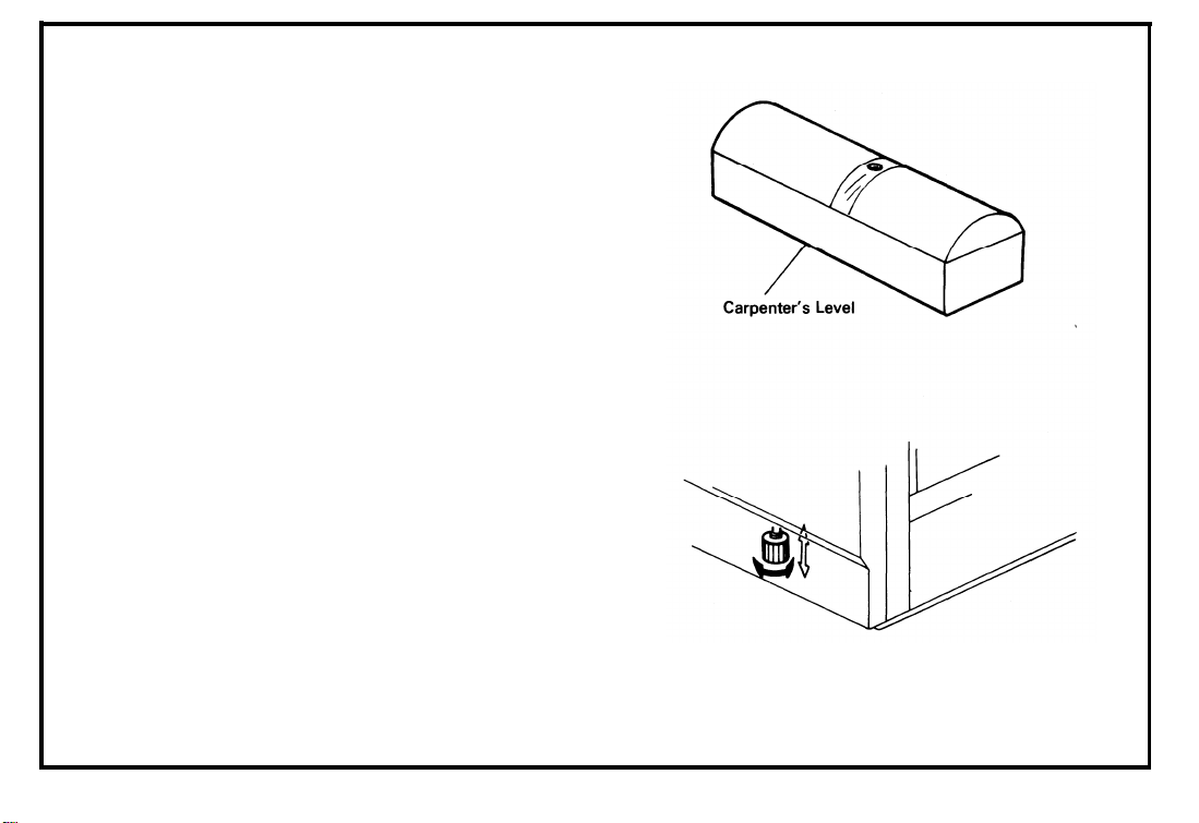
1B. Machine Level
1. Front to Back:
Within 5mm (0.2”) of level
2. Right to Left:
Within 5 mm (0.2”) of level
(Legs may be screwed up or down to level the
machine.
Set a carpenter’s level on the
exposure glass.)
1-2
Page 8
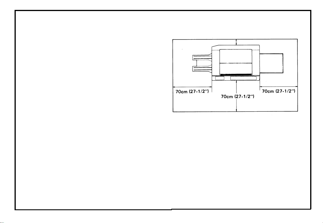
1C. Minimum Space Requirements
July 1, ’85
1. Front :
2. Back :
3. Right :
70 cm (27-1/2”)
10 cm (4“)
70 cm (27-1/2”)
4. Left : 70 cm (27-1/2”)
1Ocm (4”)
1-3
Page 9

1 D.
Power Source
1.
Input Voltage Level
110V/60Hz
115V/60Hz
: More than 12A
: More than 12A
220V/50Hz : More than 7A
240V/50Hz :
Permissible Voltage Fluctuation : ± 10%
2.
Permissible Extension Cord:
3
.
More than 7A
At least 300V, 30A capacity and less than 5
m (16.4”) long.
1-4
NOTE: 1.
Be sure to ground the machine. (Do
not connect the grounding wire to a gas
pipe.)
2.
Make sure the plug is firmly inserted in
the outlet.
Avoid multi-wiring.
3.
Do not set anything on the power cord.
4.
Page 10

SECTION 2
UNPACKING
Page 11

2. UNPACKING
2A.
Unpacking Procedure . . . . . . . . . . . . . . . . . . . . . . . . . . . . . . . . . . . . . . . . . . . . . . . . . . . . . . . . . . . . . . . . . 2-1
Accessary Check . . . . . . . . . . . . . . . . . . . . . . . . . . . . . . . . . . . . . . . . . . . . . . . . . . . . . . . . . . . . . . . . . . . . . 2-4
2B.
Page 12
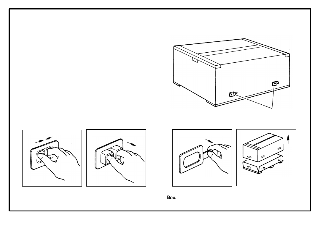
2A. Unpacking Procedure
1. Remove the 4 box joiners and the top box.
(See illustrations)
2. Take out the accessories.
3. Remove the cushion blocks.
4. Open the vinyl bag.
5. Take out the machine.
Joiners
Squeeze and pull out the inner portion of the Box Joiner.
Pull out the outer portion of the Box Jointer and take off the Top
2-1
Page 13
July 1, ’85
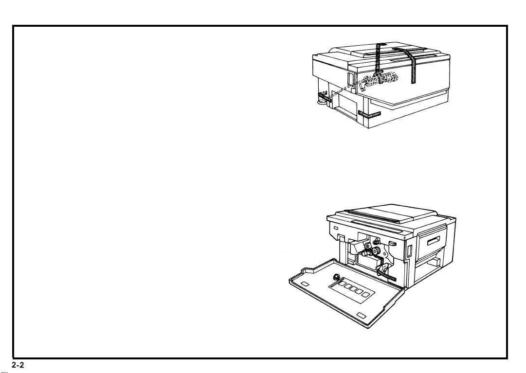
6. Remove the six strips of tape shown in the
illustrations to the right.
Page 14
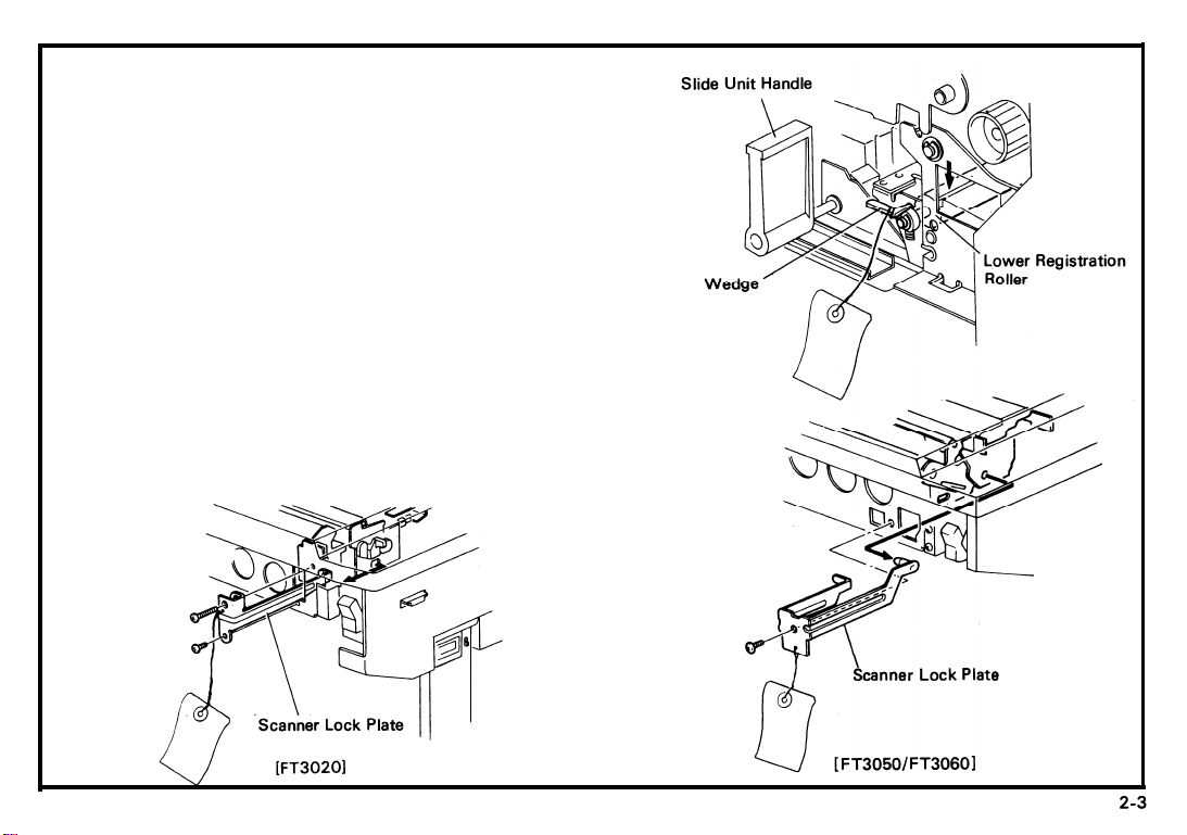
7. Grasp the slide unit handle, rotate it counterclockwise, and push it to the left.
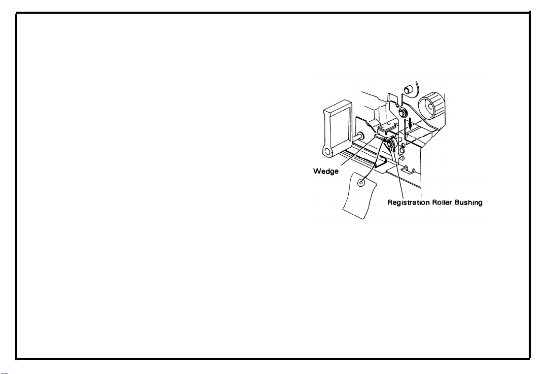
8. Remove the wedge from the lower registration
roller bushing while pushing down the lower
registration roller as shown.
9. Remove the left cover (3 screws).
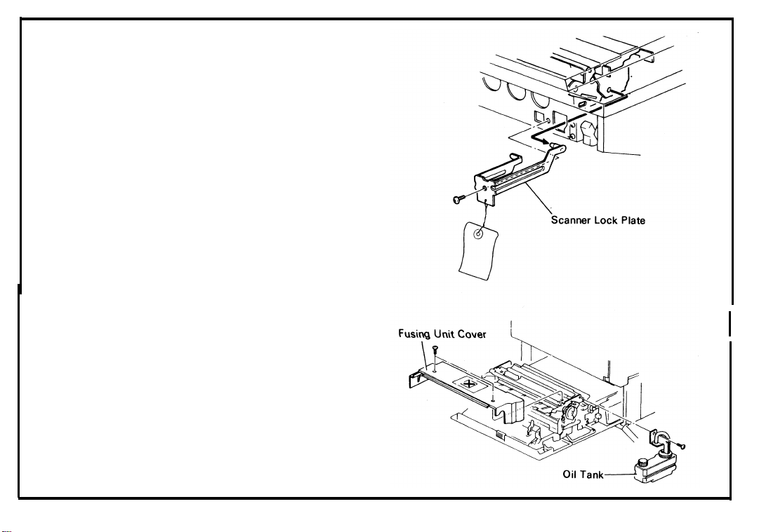
10. Remove the scanner lock plate
(2 screws [FT3020]/1 screw [FT3050/
FT3060]).
NOTE: Do not throw away the scanner lock
plate. It is necessary to reinstall it if the
copier is transported to a new location.
11. Reinstall the left cover.
July 1, ’85
Page 15

July 1, ’85
2B. Accessary Check
Check quantity and condition of the accessories in the box according to the New Equipment Condition Report
or the following list.
1.
Universal Cassette . . . . . . . . . . . . . . . . . . . . . . . . . . . . . . . . 1
2.
Cassette Magnets . . . . . . . . . . . . . . . . . . . . . . . . . . . . . . . . . 2 extra
3
.
Cassette Decals . . . . . . . . . . . . . . . . . . . . . . . . . . . . . . . . . . . 1
4.
Copy Tray . . . . . . . . . . . . . . . . . . . . . . . . . . . . . . . . . . . . . . . 1
5.
Original Holder (FT3060) only . . . . . . . . . . . . . . . . . . . . . . 1
6.
Selenium Drum . . . . . . . . . . . . . . . . . . . . . . . . . . . . . . . . . . . 1
7.
Operating Instructions . . . . . . . . . . . . . . . . . . . . . . . . . . . . . 1
8
.
Operating Instruction Holder . . . . . . . . . . . . . . . . . . . . . . . . 1
9
.
Installation Procedure . . . . . . . . . . . . . . . . . . . . . . . . . . . . . . 1
N.E.C.R . . . . . . . . . . . . . . . . . . . . . . . . . . . . . . . . . . . . . . . . . . . 1
10.
Envelope for N.E.C.R. (115V only) . . . . . . . . . . . . . . . . . . . 1
11.
2-4
Multi-lingual Decal (220/240V only) . . . . . . . . . . . . . . . . . 2 large, 1 small [FT3020]
12.
2 large, 2 small [FT3050/FT3060]
Page 16

SECTION 3
INSTALLATION
Page 17

INSTALLATION
3.
3A. Installation . . . . . . . . . . . . . . . . . . . . . . . . . . . . . . . . . . . . . . . . . . . . . . . . . . . . . . . . . . . . . . . . . . . . . . . . . . . 3-1
3B. Cassette Modification . . . . . . . . . . . . . . . . . . . . . . . . . . . . . . . . . . . . . . . . . . . . . . . . . . . . . . . . . . . . . . . . . 3-7
3C. Key Counter Holder Installation . . . . . . . . . . . . . . . . . . . . . . . . . . . . . . . . . . . . . . . . . . . . . . . . . . . . . . . . . 3-8
Page 18
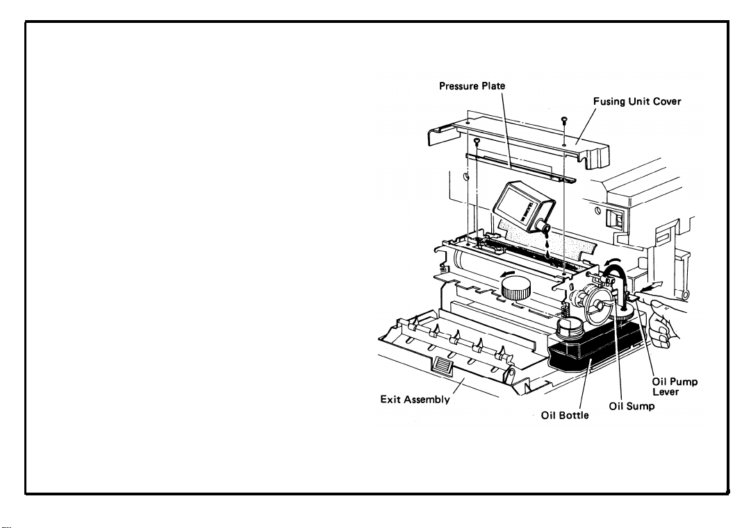
Installation
3A.
1.
Check the machine level (within 5 mm (0.2”)).
2.
Open the front cover and push the slide unit to
the left.
Open the exit assembly and fill the oil bottle
3
.
with silicone oil.
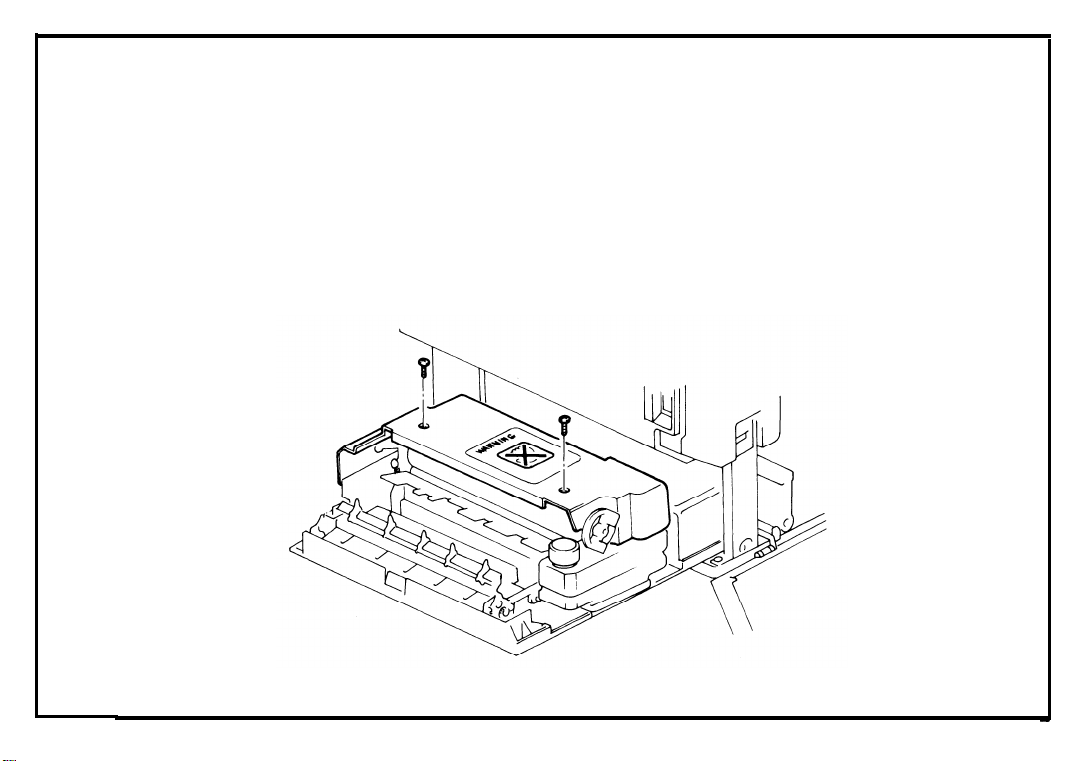
4.
Remove the fusing unit cover (2 screws) and
the pressure plate (2 non-tapping screws).
Prime the oil supply system.
5.
Pump up silicone oil by pushing the oil pump
6.
lever manually and confirm that silicone oil
drops into the oil sump.
Reassemble the fusing unit.
7.
3-1
Page 19
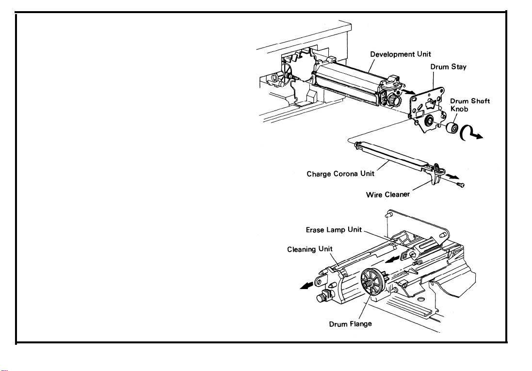
8
.
Remove the charge corona unit together with
the wire cleaner (1 screw).
Turn the drum shaft knob CLOCKWISE and
9
.
take off the drum stay.
10.
Take out the development unit and place it on
a sheet of paper.
11.
Take out the cleaning unit, the erase lamp unit,
and the drum flange.
3-2
Page 20
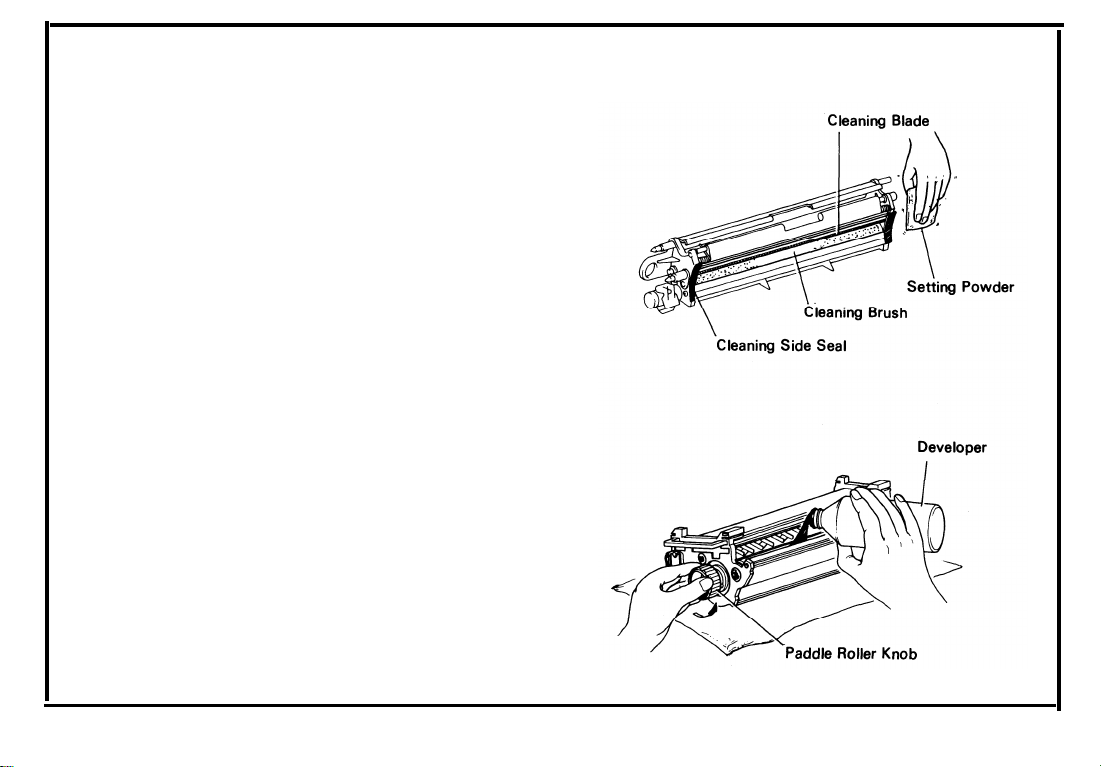
12.
Dust the drum, the cleaning blade, the cleaning brush, and the cleaning side seals with setting powder.
13.
Pour one bottle of developer (1 kg RICOH
TYPE 4000) into the development unit.
Turn the paddle roller knob counterclockwise
to smooth the developer while pouring it in.
3-3
Page 21
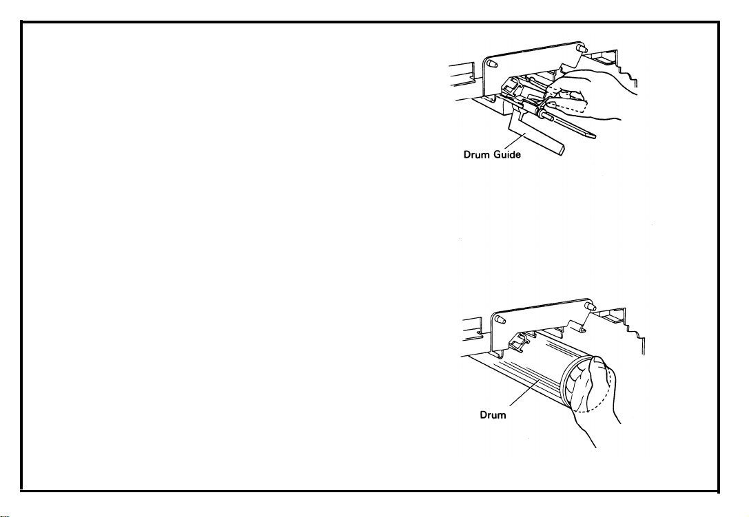
14. Pull out the drum guide and insert the drum.
15. Set the drum flange.
3-4
Page 22
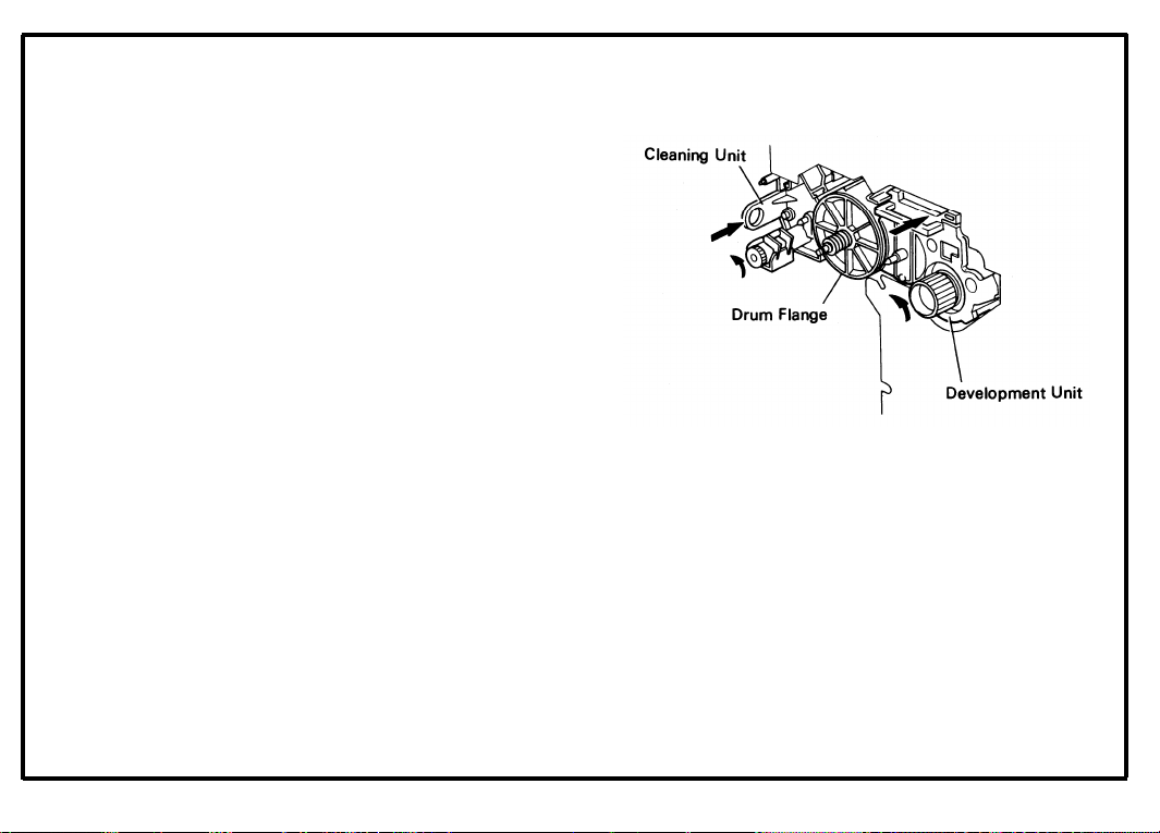
16. Insert the development unit, the cleaning unit,
and the erase lamp unit.
NOTE:
When the development unit and the clean-
ing unit are well set, their front surfaces are
flush with the drum flange.
Turn the knobs of the development and
cleaning units counterclockwise to engage
gears.
17.
Set the drum stay and the charge corona unit
with wire cleaner.
18.
Close the exit assembly and reset the slide
unit.
CAUTION: *To prevent the drum from being
damaged, do not set the slide unit
without first setting the drum stay.
*To set the slide unit firmly, push the
slide unit handle to the right.
19. Close the front cover.
3-5
Page 23
July 1, ’85
20.
21.
22.
23.
24.
25.
26.
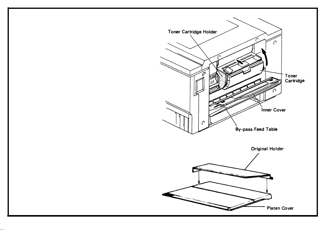
Open the by-pass feed table and the black
inner cover.
Turn down the toner cartridge holder and set a
toner cartridge.
Reset the toner cartridge holder, the inner
cover, and the by-pass feed table.
Install the original holder [FT3060].
Load paper in the cassette; then, set the
cassette and the copy tray.
Turn on the main switch, and check the
machine operation and the copy quality.
Fill out the New Equipment Condition Report.
3-6
Page 24
3B. Cassette Modification
1. Take off the cassette cover.
2. Move the side fences and the rear fence to the
desired paper size position (1 screw each).
NOTE: Paper size positions are shown on the bot-
tom of the cassette.
3. Apply the proper paper size decals on the
cassette at the positions shown.
4. Insert actuator magnets in the slots on the
front of the cassette.
NOTE: The magnet position table is also
embossed on the back side of the cassette.
5. Load paper in the cassette, replace the
cassette cover, and insert the cassette in the
cassette entrance.
6. Make copies.
and the copy image.
Check scanner return position
3-7
Page 25
July 1, ’85
Key Counter Holder Installation
3C.
Remove the front right cover (2 screws).
1.
2.
Open the front cover and remove the inner
cover (4 screws). [FT3020]
Open the front cover, push the slide unit to the
left, and remove the inner cover (5 screws).
[FT3050/FT3060]
Remove the cover plate and fixing plate from
3.
the key counter bracket.
4.
Hold the fixing plate on the inside of the key
counter bracket and insert the key counter
holder.
Align the holes in the fixing plate with the
5.
mounting holes of the key counter holder and
secure the key counter holder.
NOTE: This copier can use three types of
counter. Make sure to use the correct
holes in the fixing plate.
8. Reassemble the copier and check key counter
operation.
6. Remove the shorting plug from the key
counter connector.
7. Plug in the key counter holder.
Page 26

SECTION 4
PREPARATIONS
FOR TRANSPORTING
THE COPIER
Page 27

July 1, ’85
4. PREPARATIONS FOR TRANSPORTING THE COPIER
4A.
Preparation for Transporting the Copier [FT3020] . . . . . . . . . . . . . . . . . . . . . . . . . . . . . . . . . . . . . . . . 4-1
4B.
Preparation for Transporting the Copier [FT3050/FT3060] . . . . . . . . . . . . . . . . . . . . . . . . . . . . . . . . 4-3
Page 28
4A. Preparations for Transporting the Copier
[FT3020]
Before moving the copier from its place of installation, be sure to prepare it for transportation as
follows. The copier may be badly damaged if it is
moved without proper preparation.
1.
Take off the left cover (3 screws) and fix the
scanner in the home position with the scanner
lock plate. (ABSOLUTELY NECESSARY)
2.
Remount the left cover.
Push the slide unit to the left and remove the
3
.
fusing unit cover (2 screws).
4.
Take out the oil tank (1 screw) and empty it.
Reset the oil tank.
5.
Reinstall the fusing unit cover.
6.
4-1
Page 29
7.
Remove the toner collection bottle.
with the rubber lid and transport it separately.
8
.
Remove the drum and transport it separately
in a drum box.
9.
Remove the developer and clean the development unit.
10.
Clean the cleaning unit.
11.
Reinsert the development unit, the cleaning
unit, and the drum flange.
12.
Reset the drum stay and the charge corona
unit.
13.
Insert a wedge between the registration roller
bushing and the lower registration guide plate.
14.
Set the slide unit and tape down the slide unit
handle as shown on page 2-2.
Fix the front cover, the by-pass feed table, and
15.
the platen cover with strips of tape.
Plug it
4-2
Page 30
4B. Preparations for Transporting the Copier
[FT3050/FT3060]
Before moving the copier from its place of installa-
tion, be sure to prepare it for transportation as
follows. The copier may be badly damaged if it is
moved without proper preparation.
1.
Take off the left cover (3 screws) and fix the
scanner in the home position with the scanner
lock plate. (ABSOLUTELY NECESSARY)
Remount the left cover.
2.
Push the slide unit to the left and remove the
3.
fusing unit cover (2 screws).
4.
Take out the oil tank (1 screw) and empty it.
Reset the oil tank.
5.
Reinstall the fusing unit cover.
6.
July 1, ’85
4-3
Page 31
7.
4-4
Remove the toner collection bottle.
with the rubber lid and transport it separately.
8.
Remove the drum and transport it separately
in a drum box.
Remove the developer and clean the develop-
9.
ment unit.
10.
Clean the cleaning unit.
11.
Reinsert the development unit, the cleaning
unit, and the drum flange.
12.
Reset the drum stay and the charge corona
unit.
Insert a wedge between the registration roller
13.
bushing and the lower registration guide plate.
14.
Set the slide unit and tape down the slide unit
handle as shown on page 2-2.
Fix the front cover, the by-pass feed table, and
15.
the platen cover with strips of tape.
Plug it
Page 32

SECTION 5
REMARKS
Page 33

5. REMARKS
Points to Remember . . . . . . . . . . . . . . . . . . . . . . . . . . . . . . . . . . . . . . . . . . . . . . . . . . . . . . . . . . . . . . . . . . 5-1
5A.
Handling the Drum . . . . . . . . . . . . . . . . . . . . . . . . . . . . . . . . . . . . . . . . . . . . . . . . . . . . . . . . . . . . . . . . . . . 5-4
5B.
Toner Collection Bottle . . . . . . . . . . . . . . . . . . . . . . . . . . . . . . . . . . . . . . . . . . . . . . . . . . . . . . . . . . . . . . . . . . 5-4
5C.
Page 34

5A. Points to Remember
July 1, ’85
Drum Charge
1.
The charge corona wire should be cleaned at
every service call by sliding the corona unit.
If the corona wire cannot be cleaned using
2.
only the wire cleaner, use alcohol. Wipe the
corona wire several times in the same direction to remove all toner stains.
If copy quality
still does not improve, replace the wire.
Do not use emery paper for wire cleaning,
3.
because the corona wire is carbon coated.
Do not touch the corona wire with oily hands.
4.
Make sure that the corona wire is correctly
5.
positioned between the cleaner pads.
After cleaning the charge corona unit, make
6.
sure that there are no threads on the casing to
avoid white lines on the copy.
Exposure
1. Do not adjust the following parts:
First and Second Scanner Height Adjust-
a.
ing Cams
b. Scanner Guide Plate
Lens Axis Adjusting Cam
c.
d. Lens Position Adjusting Screw
Fourth Mirror Angle Adjusting Screw
e.
f. Exposure Lamp Adjusting Knobs
2. Launa oil or an equivalent oil should be used to
lubricate or clean the following parts:
a. Scanner Guide Rod (Cleaning)
b. Scanner Guide Rod Pads (Lubrication)
c. Scanner Guide Plate (Lubrication/
Cleaning)
d. Lens Drive Screw Shaft (Lubrication)
[FT3050/FT3060]
CAUTION: Do not use silicone oil or any other kind
of oil.
3. Do not bend or damage the lens support plate
or the mylar strip. [FT3050/FT3060]
5-1
Page 35

Oct. 1, ’83
4.
5.
6.
7.
8.
Clean the exposure glass with glass cleaner
and dry cloth.
Do not touch the following parts with bare
hands:
Reflectors
a.
b. Exposure Lamp
Mirrors and Lens
c.
Clean the mirrors with only alcohol or water
and a soft cloth.
Clean the toner shield glass with glass cleaner
at every service call.
Secure the left scale with short screws to
avoid scanner damage (M4 x 6 — 2 screws).
Toner
1.
Image density sensor should be cleaned at
every EM or PM with a blower brush.
Do not touch the sensor pattern with bare
2.
hands.
Image density sensor adjustment is required
3.
when:
a. A new drum is installed.
b. The sensor PCB or the upper registration
roller cover is moved.
c. A new sensor is installed.
Development
5-2
1. Be careful not to nick or scratch the development roller sleeve.
2. Place a sheet of paper under the development
unit when it is out of the copier.
3. Clean the development unit guide plate before
reinstalling the unit.
Cleaning
1. Do not damage the edge of the cleaning blade.
2. Do not touch the cleaning brush with oily
hands.
3. Be careful not to damage the drum with the
pick-off pawls when pulling out or inserting
the cleaning unit.
Page 36

4.
When a new cleaning blade, a new cleaning
brush, and/or new cleaning side seals are
installed, dust them with setting powder
before reinstalling the unit.
Toner collected from the cleaning unit can not
5.
be used again.
Do not adjust the blade stopper screw.
6.
Fusing
1.
After replacement of the oil blade, oil supply
pad, felt wick and the hot roller, prime with
silicone oil to the top of the oil blade.
Be careful not to damage the edge of the hot
2.
roller strippers or their tension springs.
Be careful not to bend the pressure roller strip-
3
.
pers.
4.
Do not touch the fusing lamp with bare hands.
Be sure that the fusing lamp is not in contact
5.
with the inner surface of the hot roller.
Paper Feed and Clutches
1. Grease the following parts with Mobil Temp.
78 periodically to avoid noise and bad operation:
a. Slip Clutch
b. Paper Feed Clutch
Registration Clutch
c.
d. Toner Supply Clutch
2. Periodically lubricate the paper lift motor
worm gear and worm wheel with Launa oil or
an equivalent oil.
5-3
Page 37

Handling the Drum
5B.
5C.
Toner Collection Bottle
1.
Never touch the drum surface with bare
hands.
2
.
Store the drum in a cool dry place.
Always prime the drum with setting
3.
before installing a new drum.
4.
To protect the drum, always apply setting
powder to a new cleaning blade, a new cleaning brush, and/or new cleaning side seals
before installing them.
Before installing or pulling out the drum, the
5.
cleaning unit, the development unit, and the
erase lamp unit should be removed to avoid
drum damage.
Never set the slide unit without setting the
6.
drum stay to avoid drum damage.
7.
If a blurred or fuzzy area appears in the center
of copies, it may be necessary to clean the
drum. (Use RICOH Drum Cleaning Powder.
Part No. 54479605)
powder
1.
Empty the used toner into a vinyl bag at every
service call.
2.
Teach the customers how to replace the toner
collection bottle in case it should become full
between service calls.
A rubber lid should be on the inside of the
.
3
front cover.
5-4
Page 38

SECTION 6
REPLACEMENT
AND ADJUSTMENT
Page 39

6. REPLACEMENT AND ADJUSTMENT
6A.
Optics . . . . . . . . . . . . . . . . . . . . . . . . . . . . . . . . . . . . . . . . . . . . . . . . . . . . . . . . . . . . . . . .
Development and Toner Supply . . . . . . . . . . . . . . . . . . . . . . . . . . . . . . . . . . . . . . . . . .
6B.
Cleaning . .
6C.
Paper Feed
6D.
Transport .
6E.
Fusing . . . .
6F.
Copy Image . . . . . . . . . . . . . . . . . . . . . . . . . . . . . . . . . . . . . . . . . . . . . . . . . . . . . . . . . . .
6G.
6H.
Others . . . . . . . . . . . . . . . . . . . . . . . . . . . . . . . . . . . . . . . . . . . . . . . . . . . . . . . . . . . . . . . .
. . . . . . . . . . . . . . . . . . . . . . . . . . . . . . . . . . . . . . . . . . . . . . . . . . . . . . . . . . . .
. . . . . . . . . . . . . . . . . . . . . . . . . . . . . . . . . . . . . . . . . . . . . . . . . . . . . . . . . . . .
. . . . . . . . . . . . . . . . . . . . . . . . . . . . . . . . . . . . . . . . . . . . . . . . . . . . . . . . . . . .
. . . . . . . . . . . . . . . . . . . . . . . . . . . . . . . . . . . . . . . . . . . . . . . . . . . . . . . . . . . .
. . . . . . . . . . . .
. . . . . . . . . . . .
. . . . . . . . . . . .
. . . . . . . . . . . .
. . . . . . . . . . . .
. . . . . . . . . . . .
. . . . . . . . . . . .
. . . . . . . . . . . .
6-1
6-11
6-21
6-27
6-41
6-45
6-61
6-67
Page 40

OPTICS
DEVELOPMENT AND TONER SUPPLY
CLEANING
PAPER FEED
TRANSPORT
FUSING
COPY IMAGE
OTHERS
Page 41

6A. OPTICS
July 1, ’85
6A-1.
6A-2.
6A-3.
6A-4.
6A-5.
6A-6.
6A-7.
6A-8.
6A-9.
Exposure Glass Removal . . . . . . . . . . . . . . . . . . . . . . . . . . . . . . . . . . . . . . . . . . . . . . . . . . . . . . . . . 6-2
Exposure Lamp Replacement [FT3020] . . . . . . . . . . . . . . . . . . . . . . . . . . . . . . . . . . . . . . . . . . . . 6-3
Uneven Exposure Adjustment . . . . . . . . . . . . . . . . . . . . . . . . . . . . . . . . . . . . . . . . . . . . . . . . . . . . . 6-5
Scanner Drive Wire Replacement [FT3020] . . . . . . . . . . . . . . . . . . . . . . . . . . . . . . . . . . . . . . . . . 6-7
Scanner Drive Clutch Removal [FT3020] . . . . . . . . . . . . . . . . . . . . . . . . . . . . . . . . . . . . . . . . . . . 6-9
Exposure Lamp Replacement [FT3050] . . . . . . . . . . . . . . . . . . . . . . . . . . . . . . . . . . . . . . . . . . . . 6-10
Scanner Drive Wire Replacement [FT3050/FT3060] . . . . . . . . . . . . . . . . . . . . . . . . . . . . . . . . . 6-10-a
Lens Drive Motor Replacement [FT3050/FT3060] . . . . . . . . . . . . . . . . . . . . . . . . . . . . . . . . . . . 6-10-c
Lens Home Position Sensor Adjustment [FT3050/FT3060] . . . . . . . . . . . . . . . . . . . . . . . . . . . 6-10-e
6-1
Page 42

Oct. 1, ’83
6A-1. Exposure Glass Removal
1. Take off the left scale (2 short screws).
2. Loosen the two screws that tighten down the
right side of the top cover.
3. Remove the exposure glass.
NOTE: When installing the left scale:
1)
make sure the exposure glass is flush
with the sensor pattern plate.
2)
the left scale must overlap the exposure
glass by 10 ± 0.5 mm (0.39” ±
0.02”). [FT3020]
6-2
Page 43

6A-2. Exposure Lamp Replacement [FT3020]
Oct. 1, ’83
CAUTION:
* To avoid warping the scanner, move
it by pushing or pulling the wire
clamp or drive wire only.
* Do not handle the exposure lamp with
your bare hands. Use a strip of
paper as shown. (Finger oil marks on
the lamp or reflectors will be affected
by heat, resulting in discoloration.)
1.
Remove the exposure glass and the top cover
(10 screws).
2.
Move the scanner to the middle.
3
.
Swing the reflector cover away from the
reflector and remove the rear terminal cover (2
screws, 1 flathead screw).
4.
Reset the reflector cover without screws and
move the scanner to the left (as viewed from
the rear) until the lamp is opposite the hole in
the optics unit frame.
6-3
Page 44
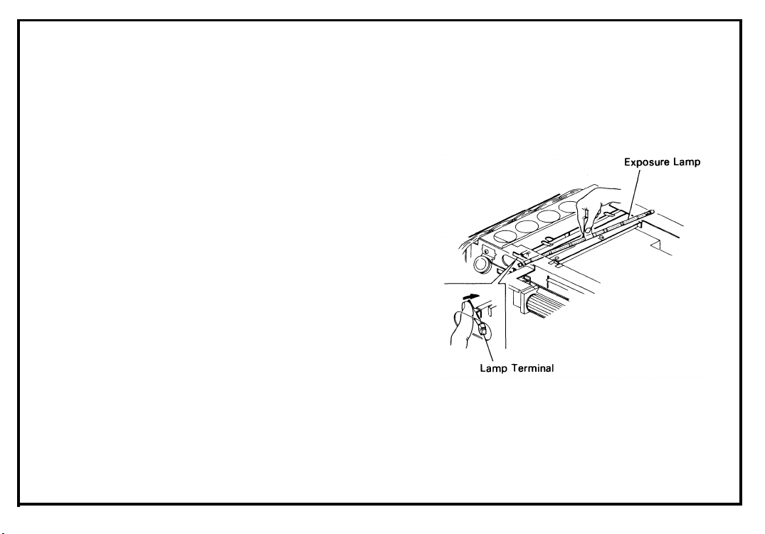
Rotate the lamp terminal as shown and take
5.
out the lamp.
Install a new lamp.
6
.
7.
Check the lamp position and light intensity.
6-4
NOTE:
* The blister on the lamp must point toward
the mouth of the reflector.
Page 45

6A-3. Uneven Exposure Adjustment
I.
Exposure Lamp Position
1.
Remove the top cover and the exposure glass
(10 screws).
2.
Verify that the lamp is properly seated.
Move the scanner to the right.
3
.
4.
Open the by-pass feed table, the black inner
cover, and the toner cartridge holder.
Remove the two cover plates (1 screw each).
5.
6.
Through the sight holes in the reflector, confirm the lamp filament position (See figure).
7.
Correct the horizontal position by tightening
or loosening the two adjusting screws.
NOTE: The vertical adjustment is done in produc-
tion only.
Oct. 1, ’83
6-5
Page 46

July 1, ’85
Il. Adjusting Plates
If uneven exposure still exists after the above
adjustment, do the following:
1. Remove the exposure glass.
2. Move the adjusting plates as shown to
increase or decrease side illumination.
NOTE: The leading edges of the three adjusting
plates must be aligned to avoid white
streak.
* Adjustment Standard:
The side to side variation
of the gray scales should
be less than 1 level.
Page 47

6A-4. Scanner Drive Wire Replacement
[FT3020]
1. Take off the Top cover (8 short screws) and
left cover (3 screws).
2. Remove the rear cover (2 screws) and the
main PCB (2 screws, 4 connectors).
3. Remove the following parts:
* Exhaust fan (3 screws)
* Inlet cooling fan (4 screws, connectors as
necessary)
* Transformer (2 screws)
– just swing to the right on the bracket.
* Scanner brake belt
* Scanner brake pulley (1 E-ring, 1 parallel key)
* Pulley shaft support plate (2 screws)
4. Loosen the wire clamp and take off the old
wire.
Oct. 1, ’83
6-7
Page 48
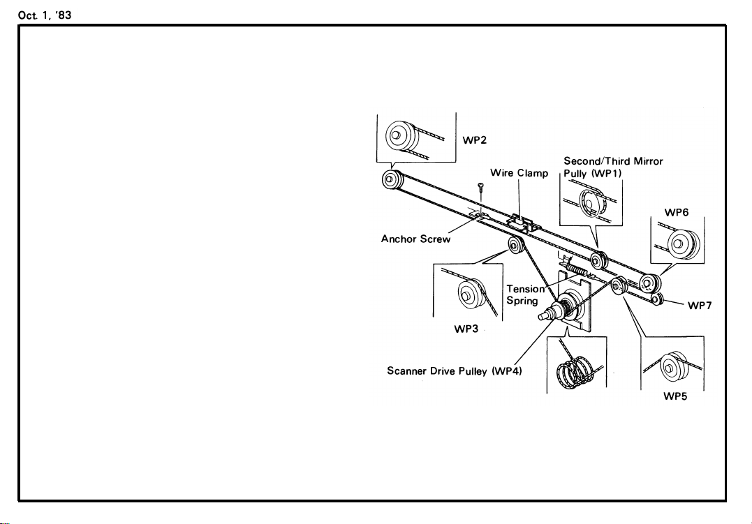
5.
Secure one end of the new wire with the
anchor screw.
6.
Run the wire under the inside track of WP1
and then through the wire clamp to WP2.
7.
Next, set the wire in the inside track of WP2
and then run it over the inside track of WP3.
8.
Wrap the wire around the scanner drive pulley
(WP4) 4 times counterclockwise, starting
from the inside edge of the pulley.
9.
Then, run the wire over the outside track of
WP5 and under the outside track of WP6.
10.
Next, run the wire over the outside track of
WP1 and around WP7.
11.
Hook the free end of the wire to the tension
spring.
12.
Tighten the wire clamp.
13.
Manually rotate the main pulley and check for
overlapping of the scanner drive wire.
14.
Reassemble the copier.
15. Check and adjust the magnification (See 6G-
1).
6-8
Page 49

6A-5. Scanner Drive Clutch Removal [FT3020]
1.
Follow Scanner Wire Replacement (6A-4)
steps 1 to 4.
2.
Slide the bearing and the scanner drive pulley
(1 shoulder screw) off of the clutch shaft.
3
Remove the scanner drive belt tightener (2
.
screws), and slide off the clutch drive pulley.
4.
Remove the anchor hook of the wire tension
spring (1 screw).
5.
Remove the, scanner
drive clutch (3 screws, 1
connector).
6-9
Page 50

6A-6. Exposure Lamp Replacement
[FT3050/FT3060]
CAUTION: * To avoid warping the scanner, move it
by pushing or pulling the wire clamp
or scanner drive pulley only.
* Do not handle the exposure lamp with
your bare hands. Use a strip of
paper as shown. (Finger oil marks on
the lamp or reflectors will be affected
by heat, resulting in discoloration.)
1.
Remove the platen cover and the platen cover
studs.
Remove the top cover and the exposure glass
2.
(10 screws).
Move the scanner to the position where the
3
.
frame is cut out.
Remove the rear reflector cover (2 screws).
4.
Rotate the lamp terminal as shown and take
5.
out the lamp.
Install a new lamp.
6.
NOTE:
* The blister on the lamp must point toward
the mouth of the reflector.
6-10
Check the lamp position and light intensity.
7.
Page 51

6A-7. Scanner Drive Wire Replacement
[FT3050/FT3060]
1.
Remove the platen cover and the platen cover
mounting studs.
2.
Remove the top cover (8 screws).
Remove the rear cover (2 screws) and the left
3.
cover (3 screws).
Remove the following parts;
4.
* Inlet cooling fan (5 screws, connectors as
necessary)
* Exhaust fan (2 screws)
NOTE: All screws on the optics frame installed in
the horizontal direction must be short
screws (M4 x 6).
Unhook the ends of the scanner drive wire.
5.
Take out the magnification change clamp and
6.
the old wire (1 screw).
July 1, ’85
Clamp the new wire to the magnification
7.
change clamp as shown.
* The left end should be about 180 mm (7.9”)
long.
6-10-a
Page 52
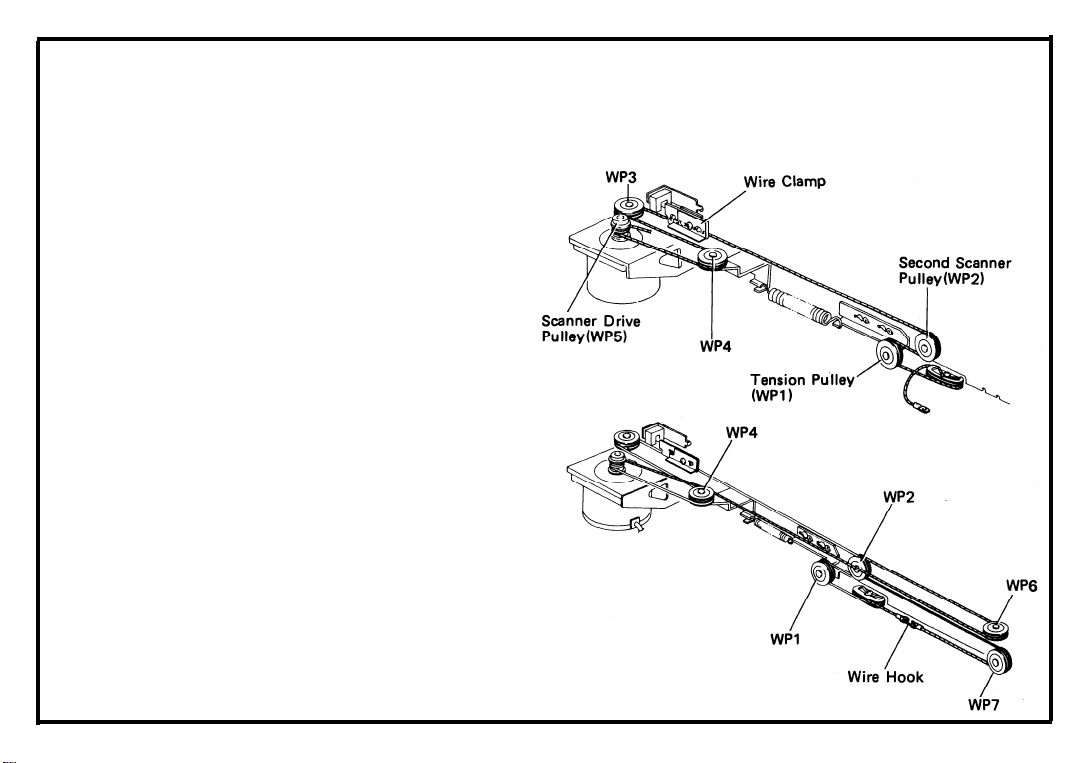
Oct. 1, ’83
Reinstall the magnification change clamp.
8.
Move the second scanner to the return posi-
9.
tion.
10.
Working from the clamp, thread the long end
of the wire in the lower groove of the clamp
and run it under the inside track of the tension
pulley (WP1).
11.
Then run the wire under the outer track of the
second scanner pulley (WP2), through the
wire clamp below the screw, and around the
lower track of WP3.
12.
Run the wire around the lower track of WP4,
and then give it two and half (2.5) turns clockwise around the scanner drive pulley, winding
from lower to upper.
13.
Next, run the wire over the upper track of
WP4, the lower track of WP6, the inner track
of WP2, and the inner track of WP7.
14.
Guide the left end of the wire through the
upper groove of the magnification change
clamp; then pull the ends of the wire together
and join them with the wire hook.
15. Reassemble the copier.
16. Check and adjust the magnification (See 6G.
5)
6-10-b
Page 53
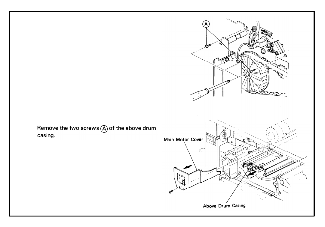
6A-8. Lens Drive Motor Replacement
[FT3050/FT3060]
1.
Remove the following parts;
* Charge Corona Unit (1 screw)
* Drum Stay
* Development Unit
* Cleaning Unit
* Erase Lamp Unit
* Quenching Lamp Unit
* Drum Flange and Drum
* Exposure Glass (4 screws)
Take off the rear cover (2 screws) and the
2.
optics PCB (1 screw, 4 connectors).
3.
4.
Take out the above drum casing (2 screws).
Take out the main motor cover (1 screw).
5.
July 1, ’85
6-10-c
Page 54

Remove the lens housing cover (3 screws).
6.
Disconnect the lens drive motor connector
7.
and disengage it from the rear side plate.
.
8
Lift up the clamps holding the lens drive motor
harness.
9.
Remove the lens drive motor assembly (2
screws).
10.
Take off the motor cover (1 screw).
11.
Remove the motor gear (1 allen screw).
12.
Replace the lens drive motor (2 screw).
13.
Reassemble.
6-10-d
Page 55

6A-9. Lens Home Position Sensor Adjustment
[FT3050/FT3060]
NOTE: When the lens home position sensor is rep-
laced or when horizontal magnification
and/or a focus will not improve by adjusting
the wire clamp, do this adjustment.
Remove the exposure glass (4 screws), the
1.
lens housing cover (3 screws), and the rear
cover (2 screws).
By turning the lens drive gear, move the lens
2.
from left to right until it reaches the full size
position.
At the full size position, a line through the
center of the cam follower and the first align-
ment hole will form a right angle with a line
through the center of the first and second
alignment holes.
July 1, ’85
6-10-e
Page 56
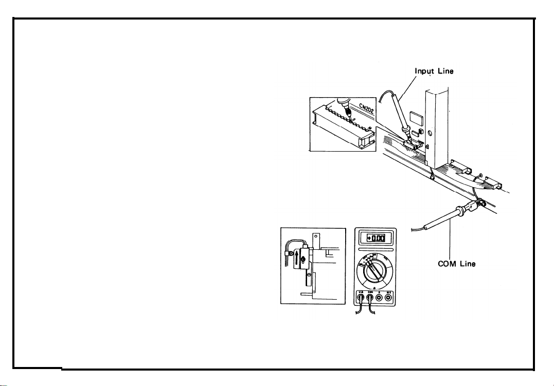
Oct. 1, ’83
3.
Open the front cover to prevent the scanner
from moving and turn on the main switch.
4.
Select the DC 20V range of the digital
multimeter, and connect the multimeters leads
— the COM line to logic ground and the input
line to CN202-9 on the optics PCB.
Loosen the sensor fixing screw.
5.
6.
Slide the sensor as far as possible toward the
right.
7.
SlowIy slide the sensor back until the
multimeter reading changes from +5V to 0V.
Tighten the sensor screw at this posttion.
8
.
Make copies and check the horizontal component of magnification and focus.
6-10-f
Page 57

July 1, ’85
6B. DEVELOPMENT AND TONER SUPPLY
6B-1. Developer Replacement . . . . . . . . . . . . . . . . . . . . . . . . . . . . . . . . . . . . . . . . . . . . . . . . . . . . . . . . . . . . 6-12
6B-2. Doctor Gap Adjustment . . . . . . . . . . . . . . . . . . . . . . . . . . . . . . . . . . . . . . . . . . . . . . . . . . . . . . . . . . . 6-13
6B-3. Toner Tank Removal . . . . . . . . . . . . . . . . . . . . . . . . . . . . . . . . . . . . . . . . . . . . . . . . . . . . . . . . . . . . . . 6-14
6B-4. Image Density Sensor Replacement . . . . . . . . . . . . . . . . . . . . . . . . . . . . . . . . . . . . . . . . . . . . . . . . . 6-15
6B-5. Image Density Sensor Adjustment [FT3020] . . . . . . . . . . . . . . . . . . . . . . . . . . . . . . . . . . . . . . . . . 6-16
6B-6. Toner Supply Clutch Disassembly [FT3020] . . . . . . . . . . . . . . . . . . . . . . . . . . . . . . . . . . . . . . . . . . 6-17
6B-7. Toner Supply Solenoid Adjustment . . . . . . . . . . . . . . . . . . . . . . . . . . . . . . . . . . . . . . . . . . . . . . . . . . 6-19
6B-8. lmage Density Sensor Adjustment [FT3050/FT3060] . . . . . . . . . . . . . . . . . . . . . . . . . . . . . . . . . . 6-20
6B-9. Toner Supply Clutch Disassembly [FT3050/FT3060] . . . . . . . . . . . . . . . . . . . . . . . . . . . . . . . . 6-20-a
6-11
Page 58

6B-1. Developer Replacement
CAUTION:
* Be careful not to bend the bias ter-
minal.
* Be careful not to damage the upper
cover seal.
* After removing used developer, clean
the drive gears.
1.
Set the development unit on a large sheet of
paper with the unit’s inlet facing downward.
2.
Turn the paddle roller knob counterclockwise.
The developer will fall out onto the paper.
3.
Hold the unit at an angle and dump out the
developer that has collected at the ends of the
development unit.
4.
Repeat the above steps until you have
removed all of the developer.
Turn the unit rightside up and pour in one bot-
5.
tle (1 kg) of RICOH TYPE 4000 developer.
6-12
Page 59

6B-2. Doctor Gap Adjustment
* Adjustment Standard: 1.25 ± 0.1 mm
(0.049” ± 0.004”)
1.
Take out the development unit and empty the
developer.
Take off the upper cover (2 screws).
2.
Before making the adjustment, confirm that
3
.
both surfaces where the thickness gauge will
be inserted are clean.
4.
Insert a 1.25 mm (0.049”) thickness gauge
5.
into the DG at the shown positions, and press
the DG plate down until the doctor blade lightly contacts the thickness guage.
6.
7.
Check that the DG is correct and even.
6-13
Page 60

6B-3. Toner Tank Removal
1.
Take out the development unit.
2.
Remove the two right covers (2 screws each).
3.
Open the by-pass feed table.
4.
Lower the inner cover.
Remove the toner tank cover (2 screws).
5.
6.
Insert a sheet of paper under the toner tank to
catch falling toner.
7.
Take out the toner tank.
(2 screws, 1 con-
nector).
6-14
Page 61

6B-4. Image Density Sensor Replacement
1. Take out the development unit, the cleaning
unit, the erase lamp unit, and the drum.
2. Remove the drum guide.
3. Remove the ID sensor PCB (1 screw, 1 connector).
4. Replace the ID sensor.
NOTE:
* Make sure the shield plate is set so that it
is held firmly by the screw.
* After replacement of the sensor, adjust
the ID sensor (See 6B-5).
6-15
Page 62

6B-5. Image Density Sensor Adjustment
[FT3020]
CAUTION: Before adjusting the ID sensor after
new drum installation, cycle the
machine about 5 times in Free Run
mode to clean the setting powder from
the drum.
NOTE: It is better to use a plastic screw driver to
avoid possible drum damage.
* Adjustment Standard : +3 ± 0.2V
1.
Remove the rear cover (2 screws).
2.
Connect a multimeter to TP105 (hot line) and
TP102 (ground line).
Turn on DIP SW101 #6.
3.
4.
Open the front cover and turn on the main
switch.
5.
Adjust the VR on the front end of the ID sen-
sor PCB.
6-16
Page 63

6B-6. Toner Supply Clutch Disassembly
[FT3020]
Remove the rear cover (2 screws).
1.
2.
Remove the main PCB (2 screws, 4 connectors).
Remove the C/B power pack holder (1 screw)
3.
and the bias lead wire clamp (1 screw).
4.
Loosen the screw securing the tension pulley
of development unit drive belt.
Remove the pulse generator sensor bracket (1
5.
screw).
Remove the development drive support
6.
bracket (3 screws).
7.
Remove the bushing from the toner supply
clutch shaft.
8.
Take off the toner supply drive pulley by turning it clockwise.
6-17
Page 64
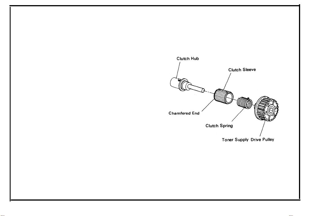
9. Remove the toner supply clutch sleeve and
spring together from the clutch hub by turning
the sleeve clockwise.
10. Clean the clutch hub, pulley, and spring, and
then grease the spring with Mobil Temp 78.
11. Reassemble.
CAUTION: When reassembling, make sure that
the chamfered end of the clutch sleeve
is to the inside. Also, make sure that
the right angle projection of the spring
is fitted into the outside notch.
6-18
Page 65
6B-7. Toner Supply Solenoid Adjustment
1. Remove the main PCB (2 screws, 4 connectors). [FT3020]
Remove the optics PCB (1 screw, 4 connectors). [FT3050/FT3060]
2. Take off the paper feed drive belt tightener (1
screw).
3. Adjust the solenoid stroke to 2 ± 0.5 mm
(0.08” ± 0.02”) (2 screws)
.
4. Check that there is at least 1 mm clearance
between the clutch pawl and the clutch sleeve
when the solenoid is on.
6-19
Page 66
July 1, ’85
6B-8. Image Density Sensor Adjustment
[FT3050/FT3060]
CAUTION: Before adjusting the ID sensor after
new drum installation,
machine about 5 times in Free Run
mode to clean the setting powder from
the drum.
NOTE: It is better to use a plastic screw driver to
avoid possible drum damage.
* Adjustment Standard : +4 ± 0.2V
Remove the rear cover (2 screws).
1.
Connect a multimeter to TPPSN (hot line) and
2.
TPGND (ground line) on the main PCB.
Turn on DIP SW101 #6.
3.
4.
Open the front cover and turn on the main
switch.
Adjust the VR on the front end of the ID sen-
5.
sor PCB.
cycle
the
6-20
Page 67
6B-9. Toner Supply Clutch Disassembly
[FT3050/FT3060]
Remove the rear cover (2 screws).
1.
Remove the optics PCB (1 screw, 4 connec-
2.
tors).
Remove the C/B power pack holder (1 screw)
3.
and the bias lead wire clamp (1 screw).
Loosen the screw securing the tension pulley
4.
of development unit drive belt.
5.
Remove the pulse generator sensor bracket (1
screw).
Remove the development drive support
6.
bracket (3 screws).
Remove the bushing from the toner supply
7.
clutch shaft.
Take off the toner supply drive pulley by turn-
8.
ing it clockwise.
July 1, ’85
6-20-a
Page 68
9. Remove the toner supply clutch sleeve and
spring together from the clutch hub by turning
the sleeve clockwise.
10. Clean the clutch hub, pulley, and spring, and
then grease the spring with Mobil Temp 78.
11. Reassemble.
CAUTION: When reassembling, make sure that
the chamfered end of the clutch sleeve
is to the inside. Also, make sure that
the right angle projection of the spring
is fitted into the outside notch.
6-20-b
Page 69

6C. CLEANING
6C-1. Cleaning Blade and Brush Replacement . . . . . . . . . . . . . . . . . . . . . . . . . . . . . . . . . . . . . . . . . . . . . . . 6-22
6C-2. Pick-off Pawl Replacement . . . . . . . . . . . . . . . . . . . . . . . . . . . . . . . . . . . . . . . . . . . . . . . . . . . . . . . . . 6-24
6C-3. Helical Coil Replacement . . . . . . . . . . . . . . . . . . . . . . . . . . . . . . . . . . . . . . . . . . . . . . . . . . . . . . . . . . . 6-25
6-21
Page 70

6C-1. Cleaning Blade and Brush Replacement
1. Take out the cleaning unit.
2. Remove the old blade (1 screw).
3. Remove the drum stay pin.
4. Remove the brush spindle.
6-22
Page 71

5. Stand the unit up on the toner return pipe as
shown; press the brush down against the
cushion, and take it out.
6. Clean the unit.
7. Check all seals, including the inner mylar seal.
Replace any that are damaged.
8. Install a new cleaning brush.
NOTE: The notched end must fit over the pin on
the gear shaft.
9. Install the new blade.
NOTE: Make sure the bushing fits in the hole of the
blade holder.
10.
Dust the edge of the new blade and the clean-
ing brush with setting powder.
6-23
Page 72
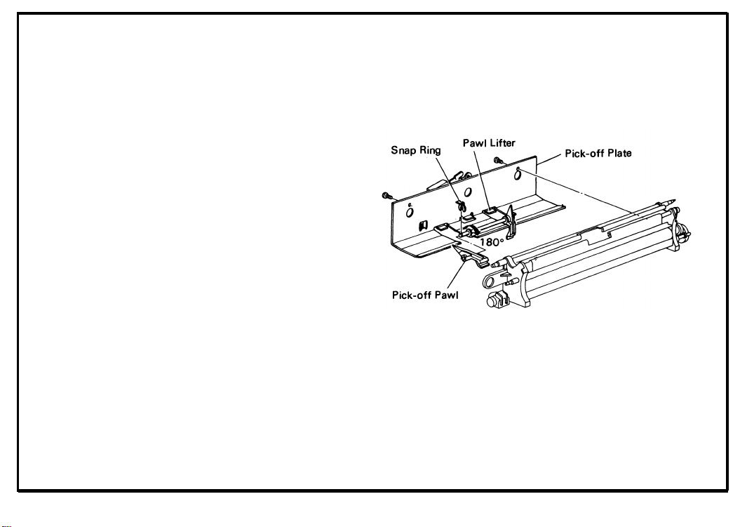
6C-2. Pick-off Pawl Replacement
CAUTION: Be careful not to damage the edge of
new pawls.
1.
Remove the pick-off plate (2 screws).
2.
Remove the snap rings from the ends of the
pick-off pawl shaft.
Rotate the pawls 180° and slip them off the
3
.
ends of the shaft as shown.
4.
Install new pawls.
NOTE: Make sure that the weighted end of each
pawI rests on the pawl lifter.
6-24
Page 73
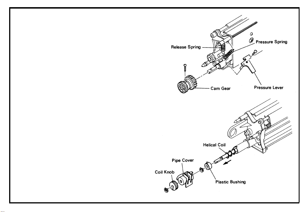
6C-3. Helical Coil Replacement
1.
Unhook the pressure and release springs.
2.
Take off the pressure lever (1 screw).
Take off the cam gear (1 screw).
3
.
Remove the coil knob (1 E-ring) and slide off
4.
the plastic pipe-cover.
Pull out the helical coil.
5.
Take off the E-ring and plastic bushing, and
6.
mount them on a new helical coil.
7.
Install the new coil.
6-25
Page 74

6D. PAPER FEED
6D-1.
6D-2.
6D-3.
6D-4.
6D-5.
6D-6.
6D-7.
6D-8.
6D-9.
Roller Replacement
l. Pick-up Roller and Feed Roller . . . . . . . . . . . . . . . . . . . . . . . . . . . . . . . . . . . . . . . . . . . . . . . . . . . 6-28
II. Separation Roller and Slip Clutch . . . . . . . . . . . . . . . . . . . . . . . . . . . . . . . . . . . . . . . . . . . . . . . . . 6-29
Paper Size Detector Replacement . . . . . . . . . . . . . . . . . . . . . . . . . . . . . . . . . . . . . . . . . . . . . . . . . . . 6-30
Paper Lift Detector Adjustment . . . . . . . . . . . . . . . . . . . . . . . . . . . . . . . . . . . . . . . . . . . . . . . . . . . . . 6-31
Paper End Detector Adjustment . . . . . . . . . . . . . . . . . . . . . . . . . . . . . . . . . . . . . . . . . . . . . . . . . . . . . 6-32
Paper Feed Solenoid and Registration Solenoid Adjustment . . . . . . . . . . . . . . . . . . . . . . . . . . . . . 6-34
Paper Feed Clutch Disassembly . . . . . . . . . . . . . . . . . . . . . . . . . . . . . . . . . . . . . . . . . . . . . . . . . . . . . 6-35
Registration Clutch Disassembly . . . . . . . . . . . . . . . . . . . . . . . . . . . . . . . . . . . . . . . . . . . . . . . . . . . . 6-37
By-pass Feed Table Removal . . . . . . . . . . . . . . . . . . . . . . . . . . . . . . . . . . . . . . . . . . . . . . . . . . . . . . . 6-39
Paper Feed Sensor Replacement . . . . . . . . . . . . . . . . . . . . . . . . . . . . . . . . . . . . . . . . . . . . . . . . . . . . 6-40
6-27
Page 75

6D-1. Roller Replacement
I.
Pick-up Roller and Feed Roller.
1. Remove the upper feed guide plate (2 screws).
2. Remove the snap ring and slide off the pick-up
roller.
3. Remove the snap ring and slide off the feed
roller.
NOTE: The feed roller must be installed with
beveled edge of the one-way bearing
the left.
6-28
Page 76

Il.
Separation Roller & Slip Clutch
1.
Remove the separation roller cover (2 screws).
2.
Take off the snap ring and slide the separation
roller off the shaft.
3
.
Slide the slip clutch off the shaft.
4.
Clean the clutch and grease it with Mobil
Temp 78.
NOTE: Put Mobil Temp 78 into the three holes of
the clutch hub.
6-29
Page 77

6D-2. Paper Size Detector Replacement
1.
Push the slide unit to the left.
2.
Take off the rear cover (2 screws).
Remove the main PCB (2 screws, 4 connec-
3.
tors). [FT3020]
Remove the optics PCB (1 screw, 4 connectors). [FT3050/FT3060]
Remove the rear spindle of the registration
4.
guide assembly (2 screws).
Take out the registration guide assembly.
5.
Remove the front inner cover (4 screws).
6.
7.
Uncouple the connector and free it from the
front side plate.
Remove the paper size detector PCB (2
8
.
screws).
NOTE: The PCB can be viewed through the left
side (slide unit) opening.
6-30
Page 78

6D-3. Paper Lift Detector Adjustment
1.
Load about 20mm (0.8”) of paper into the
cassette and set it to the copier.
Turn on the main switch.
2.
Check the clearance between the pick-up
3.
roller and the paper.
* If it is 2 ± 1 mm (0.08” ± 0.04”), the following
steps are unnecessary.
4.
Open the by-pass feed table and the inner
cover.
5.
Remove the toner tank cover (2 screws).
Move the adjusting plate of the paper lift
6.
detector up or down until the clearance is 2 ±
1 mm (0.08” ± 0.04”).
7.
Close the inner cover and the by-pass feed
table, and check the clearance between the
pick-up roller and the paper.
Remove all the paper from the cassette and
8.
check the clearance again.
6-31
Page 79
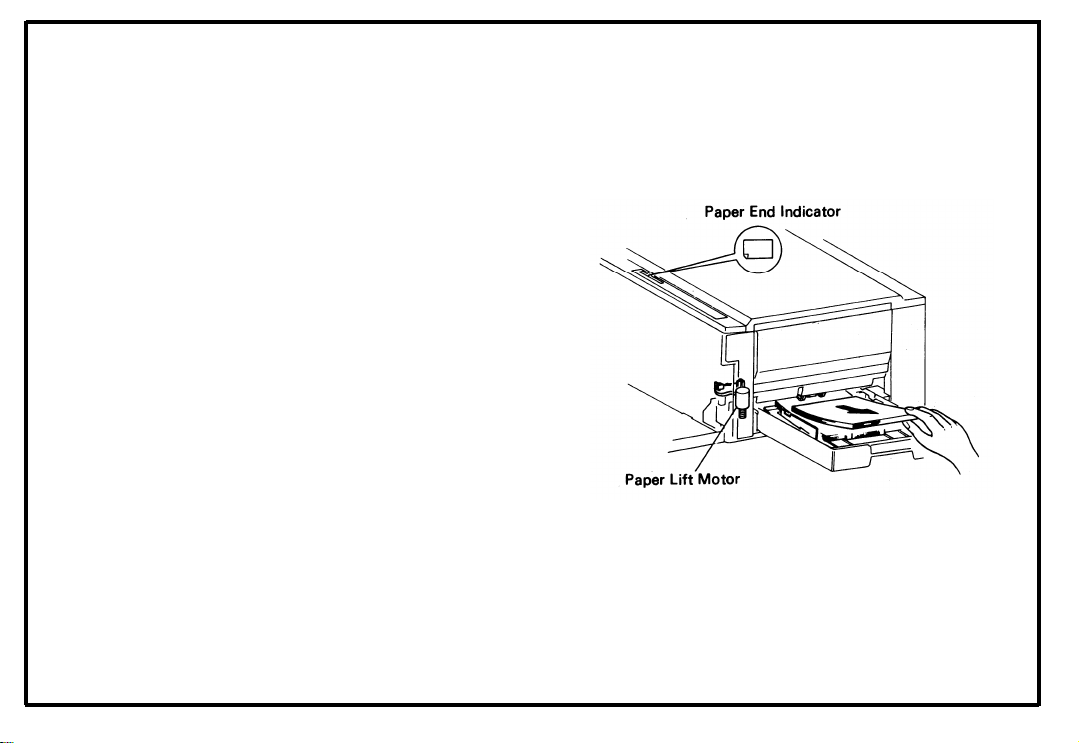
6D-4. Paper End Detector Adjustment
After adjusting the paper lift detector do this adjustment.
1.
Load about 20 mm (0.8”) of paper in the
cassette and set it in the copier.
2.
Turn on the main switch with the by-pass feed
table and the front cover closed.
Open the front cover.
3
.
4.
Remove sheets of paper little by little until the
paper end indicator lights up.
Measure the thickness of the stack of
5.
removed paper.
* If it is 3 ± 1 mm (0.12” ± 0.04“), the following
steps are unnecessary.
6-32
Page 80

6.
Open the by-pass feed table and the inner
cover.
7.
Remove the toner tank cover (2 screws).
8.
Move the adjusting plate of the paper end
detector up or down by the amount that the
measurement was out of standard in step 5.
9.
Close the inner cover and the by-pass feed
table.
Reload the paper you removed in step 4.
10.
Close the front cover to lift the paper.
11.
Repeat the above steps from 3.
12.
NOTE: Check the operation of paper end detector
with both the cassette and the by-pass
feed table.
Oct. 1, ’83
6-33
Page 81

6D-5. Paper Feed Solenoid and Registration
Solenoid Adjustment
I.
Paper Feed Solenoid
1.
2.
Check that there is some clearance between
the clutch pawl and the clutch sleeve when
the solenoid is on.
Registration Solenoid
Il.
Adjust the solenoid position to make a 1 ±
1.
0.2 mm (0.04” ± 0.008”) gap between the
clutch pawl and the clutch sleeve when the
solenoid is on.
6-34
Page 82
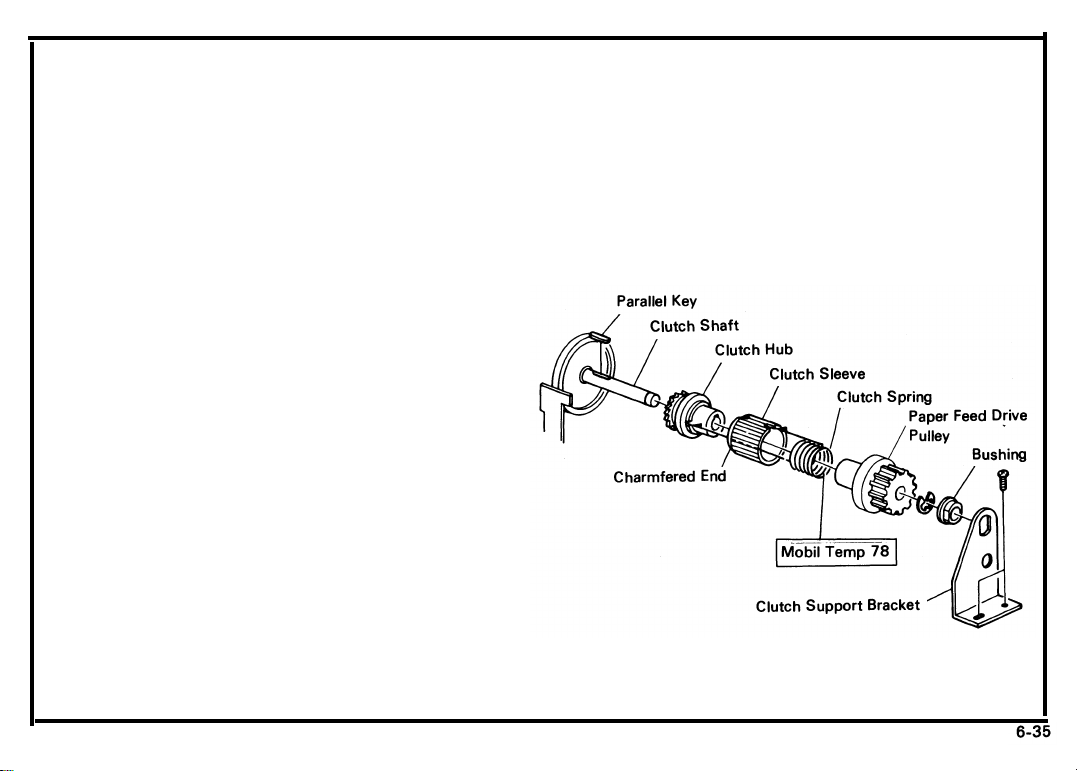
6D-6. Paper Feed Clutch Disassembly
Remove the rear cover (2 screws).
1.
Remove the main PCB (2 screws, 4 connec-
2.
tors). [FT3020]
Remove the optics PCB (1 screw, 4 connectors). [FT3050/FT3060]
Loosen the belt tension pulley (1 screw).
3
.
Remove the paper feed clutch support bracket
4.
(2 screws) and the bushing.
Take the timing belt off of the paper feed drive
5.
pulley.
Pushing the clutch pawl to the left, slide the
6.
paper feed clutch assembly off the clutch
shaft (1 E-ring).
July 1, ’85
CAUTION:
Be careful not to lose the parallel key.
7. Hold the clutch hub and, take off the paper
feed drive pulley by turning the pulley clockwise.
Page 83

8. Take the clutch sleeve and spring off of the
clutch hub.
CAUTION: Be careful not to damage the clutch
spring.
9. Clean the clutch hub, pulley, and spring.
10. Grease the clutch spring with Mobil Temp 78.
11. Reassemble.
6-36
CAUTION:
* When reassembling, make sure that
the projections on the clutch are
engaged with the clutch hub and the
clutch sleeve.
* Also, make sure that the chamfered
end of the clutch sleeve is to the
inside.
* When installing the paper feed
clutch assembly on the clutch shaft,
pull up the ratchet pawl to set the
clutch correctly.
Page 84

6D-7. Registration Clutch Disassembly
1.
Remove the rear cover (2 screws).
Remove the main PCB (2 screws, 4 connec-
2.
tors). [FT3020]
Remove the optics PCB (1 screw, 4 connectors). [FT3050/FT3060]
Unhook the tension spring of the main drive
3.
chain.
Remove the main drive chain from the
4.
registration roller drive sprocket.
Remove the E-ring from the registration roller
5.
shaft.
Slide off the clutch hub with the clutch sleeve
6.
and spring while turning the registration roller
drive sprocket clockwise.
Remove the parallel key.
7.
Pushing the registration clutch pawl to the
8.
left, take off the registration roller drive
sprocket.
July 1, ’85
6-37
Page 85

9. Clean the clutch parts and grease the clutch
spring with Mobil Temp 78.
10. Reassemble.
6-38
CAUTION:
* When reassembling make sure that
the projections on the clutch spring
are engaged with the clutch hub and
the clutch sleeve.
* Also, make sure that the chamfered
end of the clutch sleeve is to the
inside.
Page 86
July 1, ’85
6D-8. By-pass Feed Table Removal
1.
Open the front cover and remove the front
inner cover (4 screws). [FT3020]
Open the front cover, push the slide unit to the
left, and remove the inner cover (5 screws).
[FT3050/FT3060]
Remove the E-ring from the front shaft of the
2.
by-pass feed table.
Remove the right rear cover (2 screws)
.
3
4.
Open the by-pass feed table and remove the
inner cover and the toner tank cover (2
screws).
Remove the rear cover (2 screws) and the
5.
main PCB (2 screws, 4 connectors). [FT3020]
Remove the rear cover (2 screws) and the
optics PCB (1 screw, 4 connectors).
[FT3050/FT3060]
Remove the stud screw from the rear side.
6.
Take off the by-pass feed table. [FT3020]
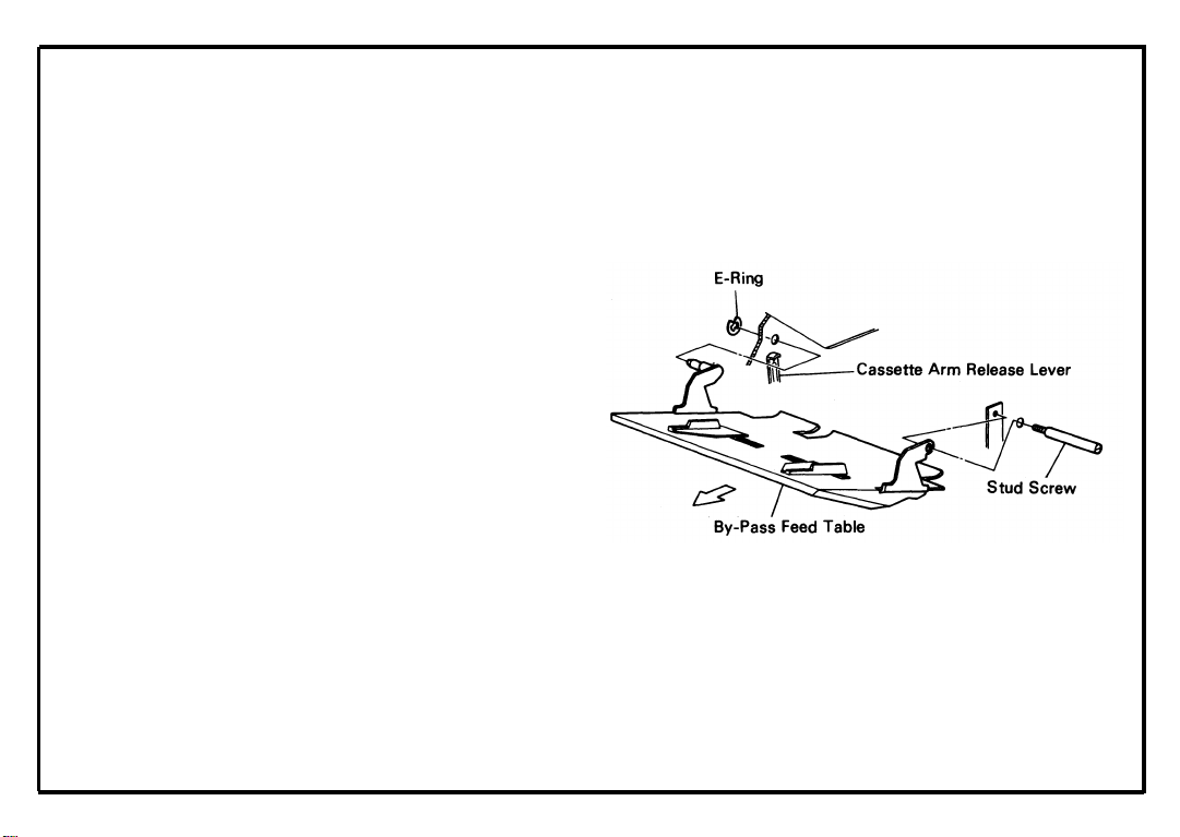
7.
(1 connector, 1 bushing) [FT3050/FT3060]
CAUTION: When reinstalling, do not damage the
cassette arm release lever nor the bypass feed table sensor.
6-39
Page 87

6D-9. Paper Feed Sensor Replacement
CAUTION: Be careful not to damage the mylar
seal.
1. Open the front cover and remove the following parts:
* Charge Corona Unit
* Drum Stay
* Development Unit
* Cleaning Unit
* Erase Lamp Unit
* Drum Flange and Drum
2. Remove the rear cover (2 screws) and the
main PCB (2 screws, 4 connectors).
3. Remove the upper registration roller cover (2
screws).
4. Turn over the upper registration roller cover
and replace the paper feed sensor (1 screw).
NOTE: After replacement of the paper feed sensor
adjust the ID sensor.
6-40
Page 88

6E. TRANSPORT
6E-1. Slide Unit Removal . . . . . . . . . . . . . . . . . . . . . . . . . . . . . . . . . . . . . . . . . . . . . . . . . . . . . . . . . . . . . . . . 6-42
6E-2. T/S Power Pack Replacement . . . . . . . . . . . . . . . . . . . . . . . . . . . . . . . . . . . . . . . . . . . . . . . . . . . . . . 6-43
6E-3. Transport Roller Replacement . . . . . . . . . . . . . . . . . . . . . . . . . . . . . . . . . . . . . . . . . . . . . . . . . . . . . . 6-44
6-41
Page 89

6E-1. Slide Unit Removal
1. Push the slide unit to the left.
2. Take off the slide unit handle (1 screw).
3. Take the slide unit out of the machine.
CAUTION:
When reinstalling the slide unit, make
sure the two accurides are set correctly.
Page 90

6E-2. T/S Power Pack Replacement
1. Remove the slide unit (See 6E-1).
2. Take off the toner collection
E-ring).
3. Unscrew the ground wire.
4. Remove the power pack
base plate (1 screw, 1
from the slide unit
connector, 2 high
voltage lines).
5. Replace the T/S power pack.
bottle holder (1
6-43
Page 91

6E-3. Transport Roller Replacement
1.
Take out the slide unit (See 6E-1).
2.
Take the fusing unit off the slide unit (See 6F-
1).
3.
Remove the toner collection bottle holder (1 Ering).
4.
Remove the transport guide plate (2 screws).
Remove the gear and bushings from the front
5.
ends of the first and second roller shafts (2 Erings).
6.
Release the tightener from the hook link chain;
then, slide the roller shafts slightly to the rear
to free the bushings and lift off the two shafts.
Remove the sprockets, clutch, etc. from the
7.
ends of the shafts and install them on the
shafts of the new rollers.
8.
Reassemble.
6-44
Page 92

6F-1.
Fusing Unit Removal . . . . . . . . . . . . . . . . . . . . . . . . . . . . . . . . . . . . . . . . .
.
. . . . . . . . . . . . . . . . . . . .
6-46
6F-2.
6F-3.
6F-4.
6F-5.
6F-6.
6F-7.
6F-8.
6F-9.
6F-10.
6F-11.
6F-12.
6F-13.
Cleaning Pad Removal . . . . . . . . . . . . . . . . . . . . . . . . . . . . . . . . . . . . . . . .
Oil Supply Pad Replacement . . . . . . . . . . . . . . . . . . . . . . . . . . . . . . . . .
Oil Blade Replacement . . . . . . . . . . . . . . . . . . . . . . . . . . . . . . . . . . . . . . . .
Hot Roller Replacement . . . . . . . . . . . . . . . . . . . . . . . . . . . . . . . . . . . . . . .
Pressure Roller Replacement . . . . . . . . . . . . . . . . . . . . . . . . . . . . . . . . . .
Hot Roller Stripper Replacement . . . . . . . . . . . . . . . . . . . . . . . . . . . . . . .
Pressure Roller Stripper Replacement . . . . . . . . . . . . . . . . . . . . . . . . . . .
Thermistor Replacement . . . . . . . . . . . . . . . . . . . . . . . . . . . . . . . . . . . . . .
Thermofuse Replacement . . . . . . . . . . . . . . . . . . . . . . . . . . . . . . . . . . . . .
Felt Wick Replacement . . . . . . . . . . . . . . . . . . . . . . . . . . . . . . . . . . . . . . .
Checking Hot Roller Temperature . . . . . . . . . . . . . . . . . . . . . . . . . . . . .
Fusing Temperature Selection and Fusing Control Unit Replacement
.
. . . . . . . . . . . . . . . . . . . .
. . . . . . . . . . . . . . . . . . . . .
. . . . . . . . . . . . . . . . . . . . .
.
. . . . . . . . . . . . . . . . . . . .
. . . . . . . . . . . . . . . . . . . . .
.
. . . . . . . . . . . . . . . . . . . .
. . . . . . . . . . . . . . . . . . . . .
.
. . . . . . . . . . . . . . . . . . . .
.
. . . . . . . . . . . . . . . . . . . .
. . . . . . . . . . . . . . . . . . . . .
.
. . . . . . . . . . . . . . . . . . . .
. . . . . . . . . . . . . . . . . . . . .
6-47
6-48
6-49
6-50
6-52
6-53
6-54
6-55
6-56
6-57
6-58
6-59
6-45
Page 93

6F-1. Fusing Unit Removal
Push the slide unit to the left.
1.
2.
Remove the connector cover (1 screw) and
uncouple the three fusing unit connectors.
Lower the exit assembly and the exit guide
3.
plate.
Remove the fusing unit from the slide unit
4.
base plate (3 screws).
NOTE: * When reinstalling this unit, make sure that
it sets properly on the positioning stud
(rear).
* Check that the gears are well engaged.
6-46
Page 94

6F-2. Cleaning Pad Replacement
1. Remove the fusing unit (See 6F-1).
2. Remove the cleaning pad (2 screws).
3. Install a new pad.
NOTE: The cleaning pad is reversable.
However, do not use the other side if it is
too oily.
6-47
Page 95
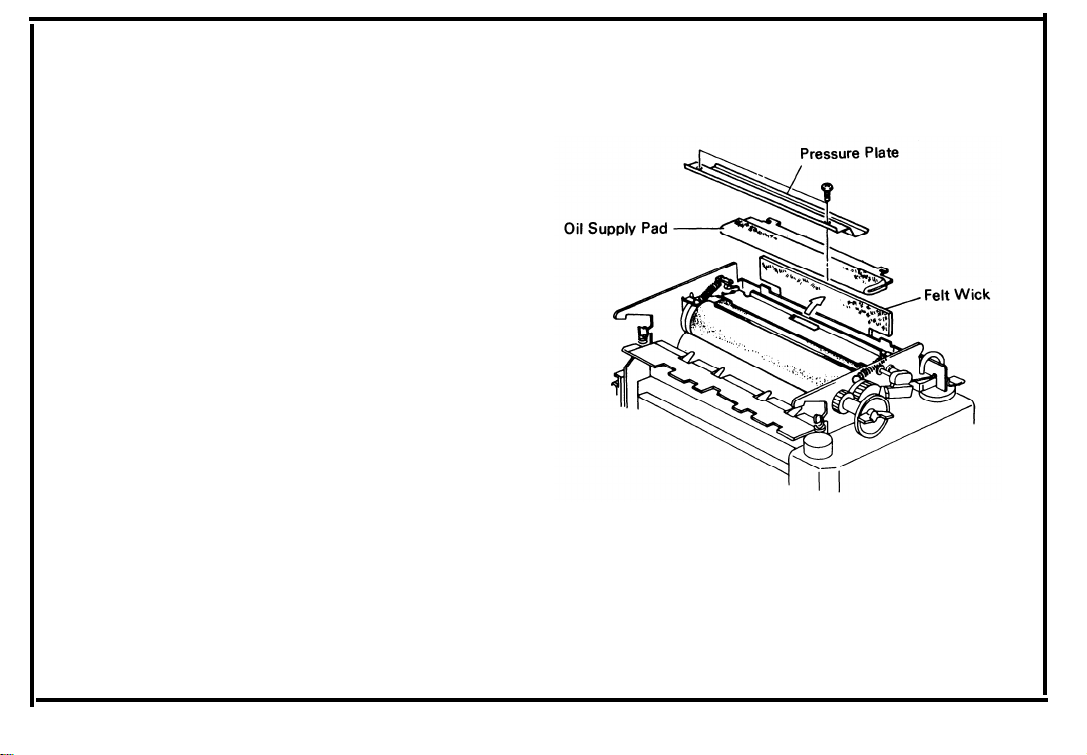
6F-3. Oil Supply Pad Replacement
1. Remove the fusing unit cover (2 screws).
2. Remove the pressure plate (2 screws).
3. Remove the oil supply pad.
4) Install a new oil supply pad.
NOTE: * Make sure that flathead side is up.
* When reassembling, use non-tapping
screws to secure the pressure plate.
6-48
Page 96

6F-4. Oil Blade Replacement
1. Remove the oil supply pad (See 6F-3).
2. Unhook the two springs and take out the oil
blade.
3. Loosen the three blade holder screws and take
out the blade.
4. Insert a new oil blade under the blade holder.
NOTE: The marked side of the blade should face
the screw-head side.
5. Fit the blade to the shape of the holder and
tighten the screws.
NOTE: * It is best to tighten the center screw first,
then fit the ends to the angled parts of the
holder and tighten the end screws.
* Use short screws (M4 x 6) to secure the
blade holder.
6. Prime the edge of the blade with silicone oil
and reassemble.
Page 97

6F-5. Hot Roller Replacement
CAUTION: When replacing the hot roller, be care-
ful not to damage the thermistor.
Remove the fusing unit (See 6F-1).
1.
Remove the oil blade (See 6F-4).
2.
3.
Take off the fusing unit knob and knob gear.
Pull and rotate the front lamp terminal, and
4.
take out the fusing lamp.
Take off the rear lamp terminal (1 screw).
5.
Unhook the pressure springs.
6.
6-50
Page 98

7.
Remove the gears, bearings, and bushings
from both ends (1 C-ring each).
8.
Slide the hot roller slightly to the rear and take
it out through the exit assembly opening.
9.
Tear the protective paper from the ends of a
new hot roller and install it carefully.
10.
After the hot roller is set, tear off the protective paper.
11.
Reassemble the fusing unit.
NOTE: Apply extra silicone oil to the oil blade to
avoid excess friction between it and the
new hot roller.
Confirm that the fusing lamp does not contact the inside of the hot roller by turning
the hot roller.
6-51
Page 99

6F-6. Pressure Roller Replacement
1.
Remove the fusing unit (See 6F-1).
2.
Take off the fusing unit cover (2 screws).
3.
Remove the cleaning pad (2 screws).
4.
Take off the oil tank (1 screw).
5.
Unhook the pressure springs.
6.
Remove the front pressure lever (1 E-ring).
7.
Remove the oil pan screw.
8
.
Lift up the upper part of the fusing unit and
take out the pressure roller.
9.
Install the bearings on a new roller’s shaft.
10.
Install the new pressure roller and reassemble.
6-52
Page 100

6F-7. Hot Roller Stripper Replacement
1. Pull out the fusing unit and open the exit
assembly.
2. Unhook the springs and take off the hot roller
strippers.
3. Snap on new strippers and connect the
springs.
6-53
 Loading...