

Ricoh FT3013 S Service Manual

A202/A203 COPIER
SERVICE MANUAL
The A202 copier is based on the A151 copier.
The A203 copier is based on the A152 copier.
Only the differences from the A151/A152 copier are described in
the following pages. Refer to the A151/A152 copier service manual
regarding the other information.
24 February 1997 SPECIFICATIONS
1. SPECIFICATIONS
NOTE: Only items marked with ✽ are different from A151 and A152 copiers.
Configuration: Desk top
Copy Process: Dry electrostatic transfer system
Original Type: Sheet/Book
Original Alignment: Left center
Original Size: Maximum:A3/11" x 17" (lengthwise) - A203 copier
B4/10" x 14" (lengthwise) - A202 copier
Copy Paper Size: Maximum:B4/10" x 14" (lengthwise)
Minimum:
Paper Tray: A5/51/2" x 81/2" (lengthwise)
Bypass Feed: A6/51/2" x 81/2" (lengthwise)
Copier
A202/A203
Copy Paper Weight: Paper tray feed -- 64 to 90 g/m2 (17 to 24 lb)
Bypass feed -- 52 to 105 g/m2 (14 to 28 lb)
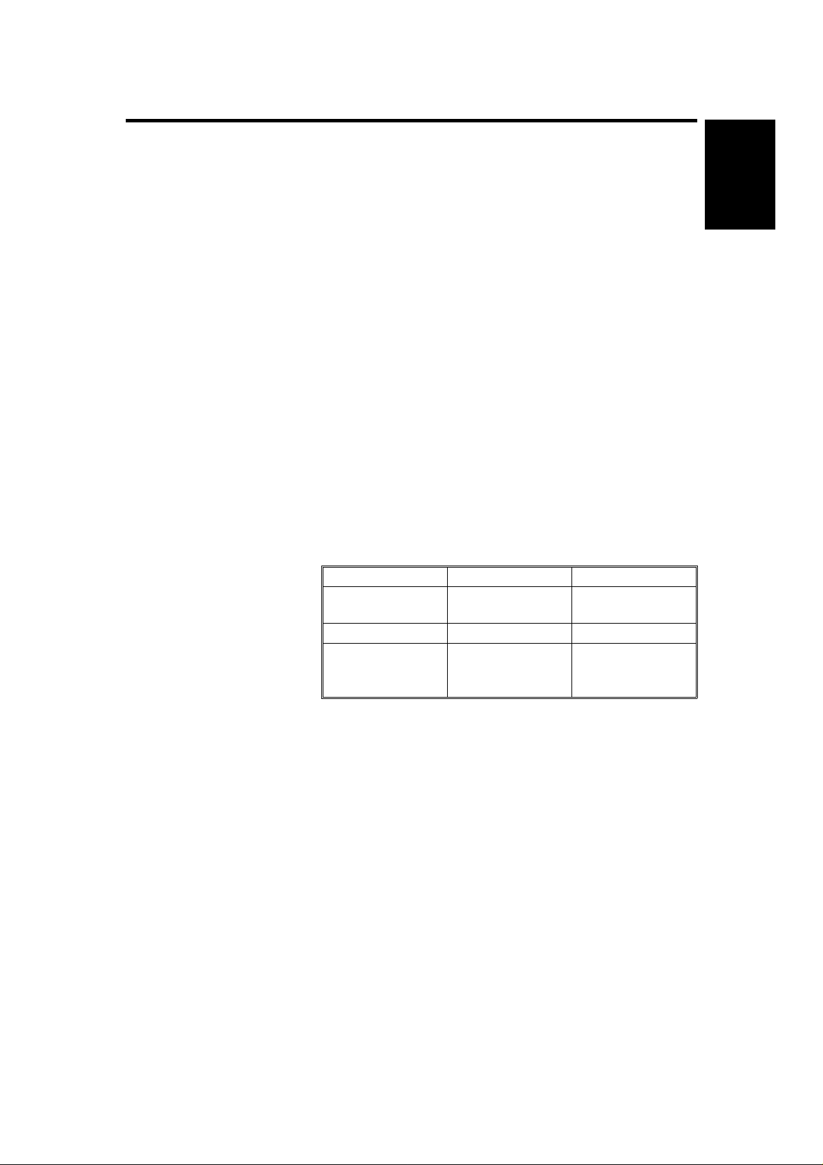
Reproduction Ratios: 2 Enlargement and 3 Reduction (A203 copier only)
A4 Version Letter Version
Enlargement
Full size 100% 100%
Reduction
141%
122%
93%
82%
71%
129%
121%
93%
74%
65%
Zoom: From 61% to 141% in 1% steps
(A203 copier only)
Copying Speed: 13 copies/minute (A4/81/2" x 11" lengthwise)
10 copies/minute (B4/81/2" x 14")
Warm-up Time:
30 seconds (at 20°C/68°F)
First Copy Time: 9 seconds (A4/81/2" x 11" lengthwise)
Copy Number Input: Number keys, 1 to 99
Manual Image Density
7 steps
Selection:
1
SPECIFICATIONS 24 February 1997
Automatic Reset: 1 minute standard setting; can also be set to 3
minutes or no automatic reset.
Energy Saver Function: Automatic
Paper Capacity: Paper tray -- 250 sheets or less than 28 mm stack
height
Bypass feed table -- 1 sheet
Toner Replenishment: Cartridge exchange (320 g/cartridge)
Copy Tray Capacity: 100 sheets (B4/10" x 14" or smaller)
1 sheet (OPC)
✽ Power Source: 110 V/60 Hz/15 A (for Taiwan)
120 V/60 Hz/15 A (for North America)
220 V ~ 240 V/50 Hz/8 A (for Europe)
220 V/50 Hz/8 A (for Middle East)
220 V/60 Hz/8 A (for Saudi Arabia)
220 V/50 Hz/8 A (for Asia)
Refer to the serial number plate (rating plate) to
determine the power source required by the
machine.
Power Consumption:
Copier Only With DF
Maximum 1.4 kVA 1.5 kVA
Warm-up 620 VA (average) 640 VA (average)
Copy cycle 810 VA (average) 860 VA (average)
Ready 160 VA (average) 180 VA (average)
✽ Noise Emission:
Sound power level (The measurements are made in accordance with ISO
7779.)
Copier Only Copier with document feeder
Copy cycle Less than 64 dB Less than 62 dB
Stand by Less than 55 db Less than 40 dB
Sound pressure level (The measurements are made in accordance with ISO
7779 at the operator position.)
Copier Only Copier with document feeder
Copy cycle Less than 58 dB Less than 62 dB
2

24 February 1997 SPECIFICATIONS
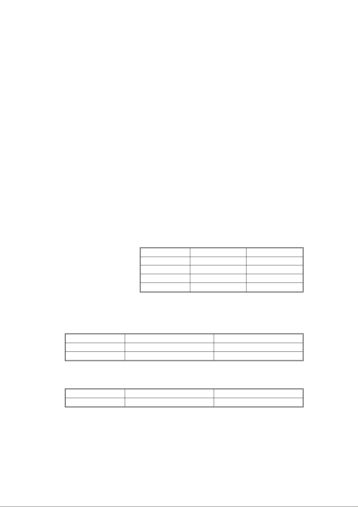
Dimensions:
Width Depth Height
Copier with platen cover and
copy tray
Copier with document feeder
and copy tray
713 mm (28.1") 592 mm (23.3") 400 mm (15.7")
713 mm (28.1") 592 mm (23.3") 463 mm (18.2")
Weight: Copier only: 43 kg (94.8 lb)
With DF: 50 kg (110.2 lb)
Copier
A202/A203
Optional Equipment:
(Sales items)
Optional Equipment:
(Service items)
Document feeder (A203 copier only)
Key counter
Drum anti-condensation heater
Optics anti-condensation heater
Pre-transfer lamp
• Specifications are subject to change without notice.
3
COPY PROCESS CONTROL 24 February 1997
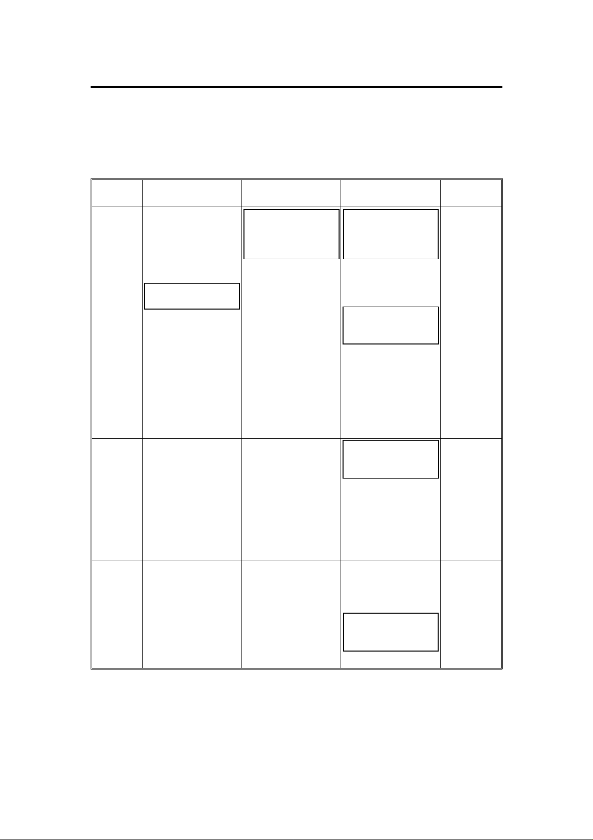
2. COPY PROCESS CONTROL
• Drum residual voltage (VR) correction and detection have been
eliminated.
• Drum wear correction has been eliminated.
Image
Density
Control
Toner
Density
Detection
Grid Voltage
Standard image
density grid voltage
(--680 V)
+
Auto image density
level factor (SP34)
Standard ID sensor
grid voltage
(--460 V)
Exposure Lamp
Voltage
Base exposure
lamp voltage
(Manual or ADS
mode) (SP48)
+
VL correction factor
+
Reproduction ratio
correction factor
(A203 copier only)
Same as image
density control
Development Bias
Voltage
Base bias voltage
factor
(Manual or ADS
mode) (SP34)
+
Image bias voltage
adjustment factor
(SP37)
+
Note:
Base bias voltage at
manual ID level 7
can be adjusted with
SP50
Depends on ID
sensor bias setting
(SP33)
Note:
For the initial 499
copies, bias voltage
is increased by --20
volts
Erase Lamp
Depends on
paper size
and
reproduction
ratio
ID sensor
pattern
erase (Vsg
detection:
Full erase)
Between
Copies
0 Volts (Fixed) Exposure lamp turns
off
--160 Volts (Fixed)+Full erase
Image bias voltage
adjustment factor
(SP37)
NOTE: The boxed items can be adjusted by SP mode.
4
(All LEDs
ON)
24 February 1997 MECHANICAL COMPONENT LAYOUT
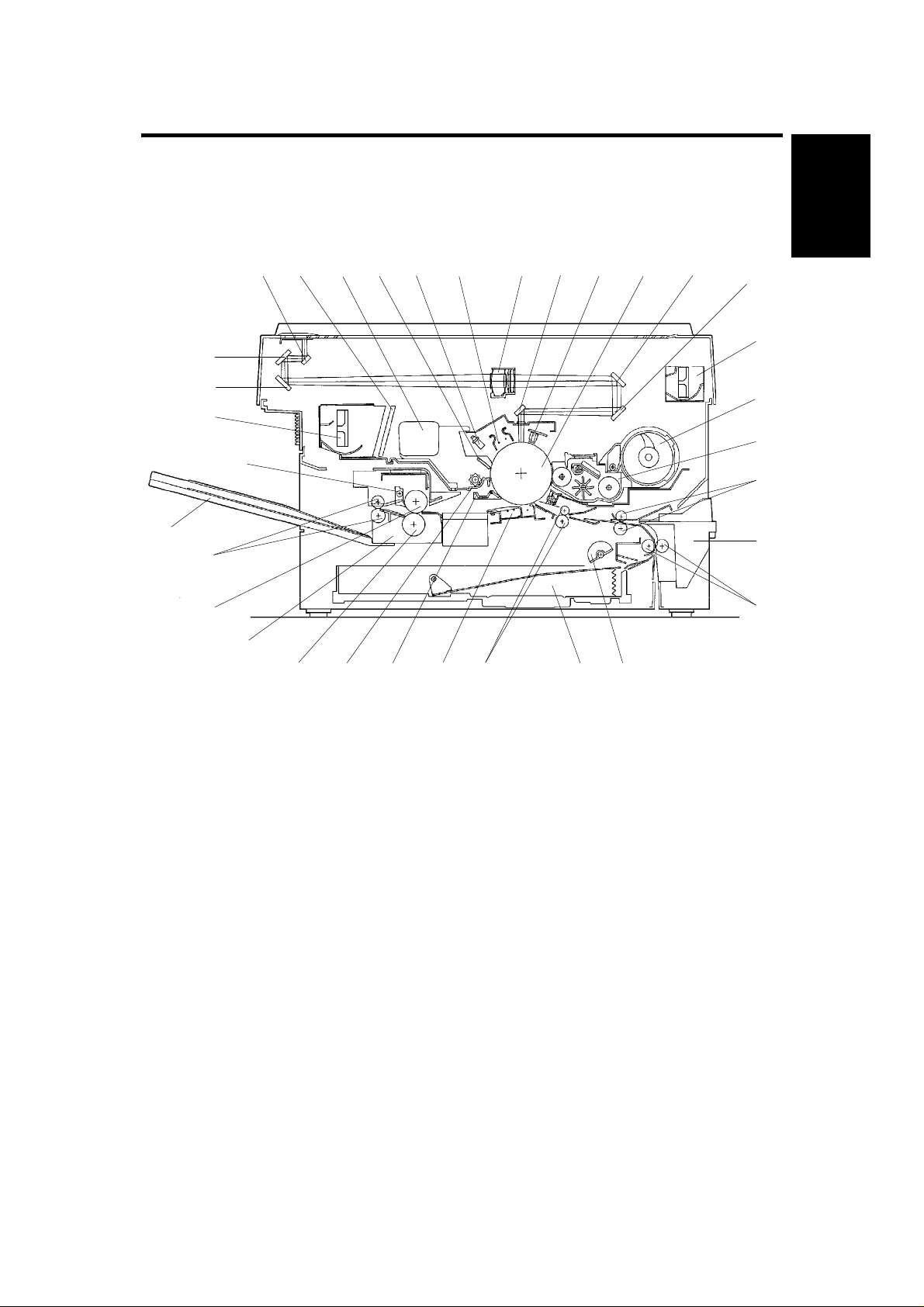
3. MECHANICAL COMPONENT LAYOUT
NOTE: Only items marked with ✽ are different from A151 and A152 copiers.
16
18 19 20 21 22
17
23 24 25
26
27
Copier
A202/A203
15
14
13
12
11
10
9
8
7
1. Semicircular Feed
Rollers
2. Paper Tray
3. Registration Rollers
4. Transfer and
Separation Corona Unit
5. Pick-off Pawl
6. Cleaning Unit
7. Pressure Roller
8. Fusing Unit
9. Hot Roller
10. Exit Rollers
11. Copy Tray
12. Hot Roller Strippers
13. Exhaust Blower Motor
14. 3rd Mirror
15. 2nd Mirror
16. 1st Mirror
17. Ozone Filter
18. Used Toner Tank
19. Cleaning Blade
20. Quenching Lamp
21. Charge Corona Unit
22. Lens
123456
A203V500.img
23. 6th Mirror
24. Erase Lamp
25. Drum
26. 4th Mirror
27. 5th Mirror
28. Optics Cooling Fan
✽
Motor (in A202 & A203)
29. Toner Supply Unit
30. Development Unit
31. 2nd Relay Rollers
32. By-pass Feed Table
33. 1st Relay Rollers
28
29
30
31
32
33
5
ELECTRICAL COMPONENT LAYOUT 24 February 1997
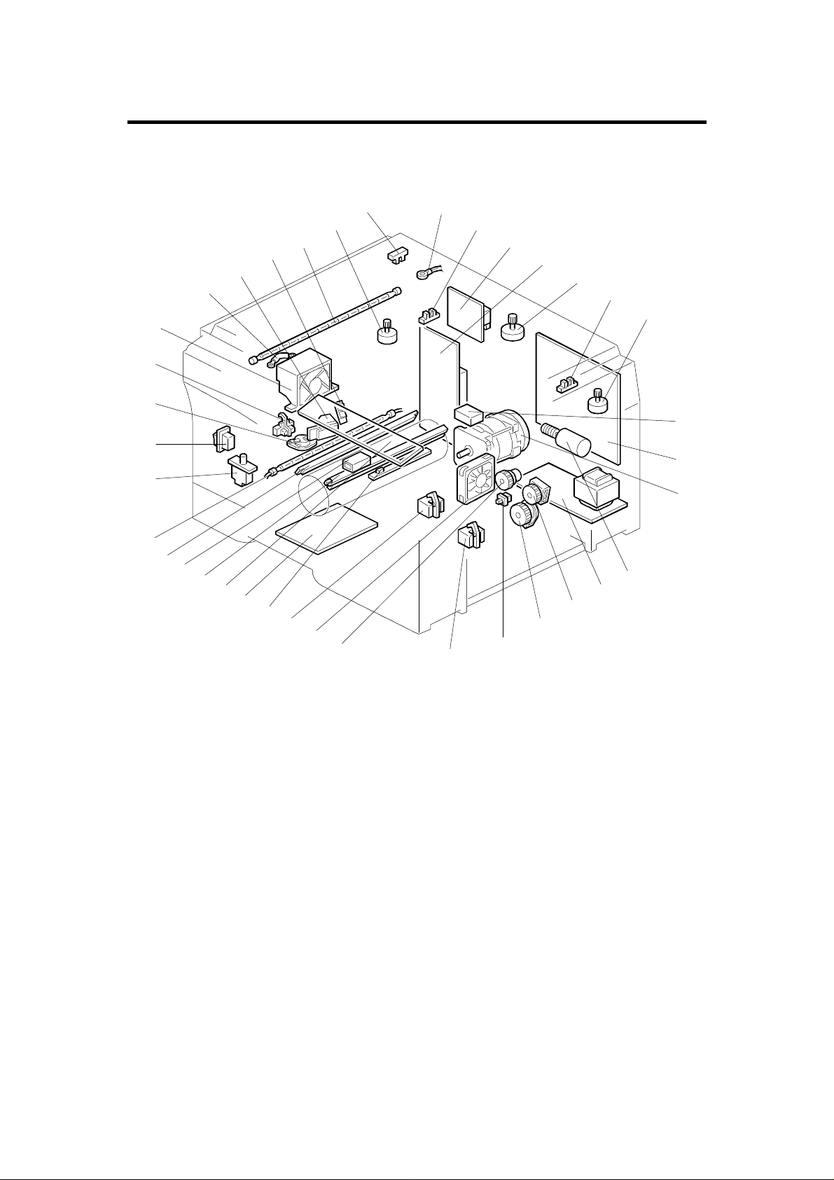
4. ELECTRICAL COMPONENT LAYOUT
NOTE: Only items marked with ✽ are different from A151 and A152 copiers.
17
16
15
14
13
12
11
10
9
18
23
22
21
20
19
24
25
26
27
29
30
31
32
33
34
8
7
6
5
4
3
1
37
38
2
35
36
A203V501.img
1. Paper Tray Switch
2. Relay Sensor
3. Registration Clutch
✽
4. Optics Cooling Fan Motor
5. Registration Sensor
6. Image Density Sensor
7. Power Pack-TC/SC
8. Operation Panel Board
9. Erase Lamp
10. Total Counter
11. Quenching Lamp
12. Fusing Lamp
13. Front Cover Safety Switch
14. Main Switch
15. Fusing Thermoswitch
16. Exit Sensor
17. Exhaust Blower Motor
18. Optics Thermofuse
19. Auto Image Density
Sensor
20. Fusing Thermistor
21. Exposure Lamp
22. Lens Motor
(A203 copier only)
23. Scanner Home Position
Sensor
24. Optics Thermistor
25. Lens Home Position
Sensor (A203 copier only)
26. Power Pack-CC/Grid/Bias
NOTE: Index No. 28 is not applicable for this model.
6
27. AC Drive Board
28. N/A
✽
29. Scanner Motor
30. 4th/5th Mirror Home
Position Sensor
(A203 copier only)
31. 4th/5th Mirror Motor
(A203 copier only)
32. Main Motor Capacitor
33. Main Board
34. Main Motor
35. Toner Supply Motor
✽
36. DC Power Supply Board
37. Relay Roller Clutch
38. Paper Feed Clutch

24 February 1997 ELECTRICAL COMPONENT DESCRIPTIONS
5. ELECTRICAL COMPONENT DESCRIPTIONS
The following motor is included as an electrical component.
Symbol Name Function Index No.
M7 Toner Supply Motor Drives the toner supply roller. 35
The following clutch and triac are not included in this copier.
Symbol Name Function Index No.
MSC1 Toner Supply Clutch Drives the toner supply roller. 35
Copier
A202/A203
TR
Fusing Triac
(115 V only)
Switches the fusing lamp on and off.
28
The following part has been changed.
Symbol Name Function Index No.
Quenching Lamp Receives dc power from the main board (the
L3
lamp in the A151/A152 received ac power
from the ac drive board).
11
7
DRIVE LAYOUT 24 February 1997
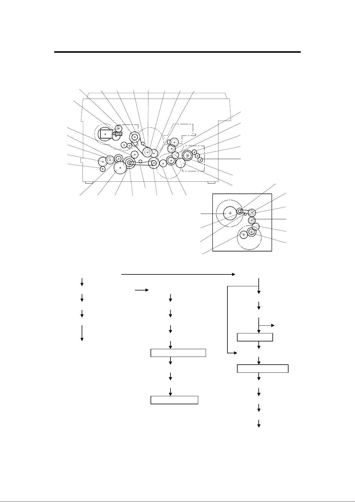
6. DRIVE LAYOUT
NOTE: Only items marked with ✽ are different from A151 and A152 copiers.
BP5 G11
✽ G13
✽ G14
TB3BP6G12
G10 G23
G9
G15
G16
G17
G18
G19
G20 G21 G22 BP2
Main Motor Gear
G1:
Timing Belt Drive Gear
G23:
Timing Belt Pulley
BP1:
Timing Belt
TB1:
TB1
BP1 G1 G2
A203V502.img
G26
G25
TB2
G1
Relay GearG10:
Timing Belt Drive GearG11:
Timing Belt PulleyBP5:
G4
G3
G8
G7
G6
G5
BP4
BP3
G24
G9
G8
G2
A203V503.img
Relay GearG2:
Relay GearG8:
Relay GearG9:
B
A
A203V504.wmf
Timing BeltTB3:
Development Section
Timing Belt PulleyBP6:
Development GearG12:
Development Unit
8
G3:
Cleaning Unit
Fusing Drive Gear
G3:
Fusing and Exit Unit
Hot Roller GearG4:
Relay GearG7:
Relay GearG6:
Exit Roller GearG5:
24 February 1997 DRIVE LAYOUT
Registration CL Gear
G1:
Registration CL
Registration Rollers
Relay GearG20:
Relay Roller CL GearG17:
Relay Roller CL
2nd Relay Roller GearG16:
2nd Relay Rollers
A B
Paper Feed Section
BP2: Timing Belt Pulley
Relay GearG22:
Paper Feed Section
Paper Feed CL GearG21:
Paper Feed CL
Feed Rollers
G24:
G25:
✽ G13:
Copier
A202/A203
Timing Belt Drive
Gear
Timing Belt PulleyBP3:
Timing BeltTB2:
Timing Belt PulleyBP4:
Relay Gear
Drum Drive GearG26:
Toner Supply Motor
Gear
1st Relay Rollers GearG19:
1st Relay Rollers
✽ G14:
✽
Toner Supply Gear
Toner Supply Unit
A203V505.wmf
9
POWER DISTRIBUTION 24 February 1997
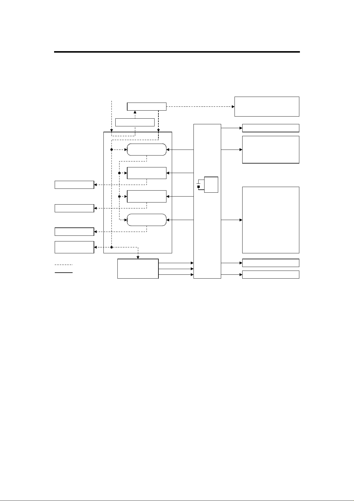
7. POWER DISTRIBUTION
NOTE: Only items marked with ✽ are different from A151 and A152 copiers.
Exposure Lamp
Document Feeder
(Option)
AC Power (115V or 220V ~ 240V)
Fusing Lamp
Main Motor
AC power
DC power
Main SW
Cover Safety SW
Power Relay
(RA401)
Fusing Lamp
Drive Circuit
Exposure Lamp
Drive Circuit
Relay (RA402)
AC Drive Board
DC Power
Supply Board
24V (VA)
24V (VA)
24V (VA)
24V (VA)
24V (VA)
5V (VC)
Zero Cross
RAM
Pack
Main
Board
5V
Scan
Signal
5V (VC)
24V (VA)
5V (VC)
24V (VA)
Anti-condensation Heaters
-Drum (Option)
-Optics (Option)
Operation Panel Board
Sensors
Thermistors
Solenoids
Clutches
Power Packs
Lens Motor
(A203 copier only)
4th/5th Mirror Motor
(A203 copier only)
✽ Optics Cooling Fan Motor
✽
Toner Supply Motor
✽ Quenching Lamp
Scanner Motor
A203D500.wmf
When this copier is plugged in and the main switch is turned off, ac power is
supplied via the ac drive board to the optional anti-condensation heaters.
When the front cover and/or the exit cover is open, the cover safety switch
completely cuts off power to all ac and dc components.
When the main switch is turned on, the ac power supply to the
anti-condensation heater is cut off and ac power is supplied to the ac drive
board. The dc power supply board receives wall outlet ac power through the
ac drive board.
The dc power supply board converts the wall outlet ac power input to +5
volts, +24 volts, and a zero cross signal, all of which are supplied to the main
board.
10

24 February 1997 POWER DISTRIBUTION
The main board supplies dc power to all copier dc components. All sensors,
switches, thermistors, and the DF interface board (option) operate on +5
volts. The operation panel operates on +5 volts supplied by the main board.
All other dc components, including the power relay (RA401) and the main
motor relay (RA402), operate on +24 volts.
When the main board receives power, it activates the power relay (RA401),
which then supplies ac power to the fusing lamp drive circuit and the
exposure lamp drive circuit on the ac drive board. The fusing lamp drive
circuit receives a trigger signal from the main board and the fusing lamp
lights. The exposure lamp does not turn on until the main board sends a
trigger pulse to the exposure lamp drive circuit.
When the key is pressed, the main board energizes the main motor relay
(RA402). Then, the main motor turns on.
When the main switch is turned off, power to the main board and to RA401 is
cut off, and the optional drum and optics anti-condensation heaters are
turned on.
Copier
A202/A203
11
DRUM CHARGE 24 February 1997
8. DRUM CHARGE
8.1 GRID VOLTAGE CORRECTION
This machine does not correct drum residual voltage correction (VR
correction) or drum wear correction.
8.2 GRID VOLTAGE FOR IMAGE DENSITY CONTROL
The main board controls the grid voltage through the CC/Grid/Bias power
pack. As the grid voltage for the image density control becomes less, the
copy image becomes lighter, and vice versa.
The grid voltage for image density is based as follows:
Grid Voltage = Standard image density grid voltage (--680 volts [SP60 = 4])
+
Auto image density level factor (SP34)
8.2.1 Standard Image Density Grid Voltage
The standard image density grid voltage (SP60) is set at the factory and the
setting is different for each machine. The setting of SP60 is printed on the SP
mode data sheet located inside the inner cover of the machine.
8.2.2 Auto Image Density Level Factor (SP34)
Auto image density level Data (SP34) Change of grid voltage (volts)
Normal 0 *
Darker 1 --40
Lighter 2
±0
±0
* Factory setting
The grid voltage and the exposure lamp voltage are constant regardless of
the output from the auto image density sensor. Only the development bias
voltage varies depending on the output from the auto image density sensor.
When the auto image density level data in SP34 is set to darker, the grid
voltage is changed --40 volts as shown in the above table. When it is set to
lighter, the grid voltage does not change. However, the development bias
voltage is corrected.
12

24 February 1997 DRUM CHARGE
8.3 GRID VOLTAGE FOR TONER DENSITY DETECTION
The grid voltage for toner density detection is based on the standard ID
sensor grid voltage.
Grid voltage = Standard ID sensor grid voltage (--460 volts [SP62=4])
The standard ID sensor grid voltage (SP62) is set at the factory and the
setting is different for each machine.
The setting of SP62 is printed on the SP mode data sheet located inside the
inner cover of the machine.
Copier
A202/A203
13

OPTICS 24 February 1997
9. OPTICS
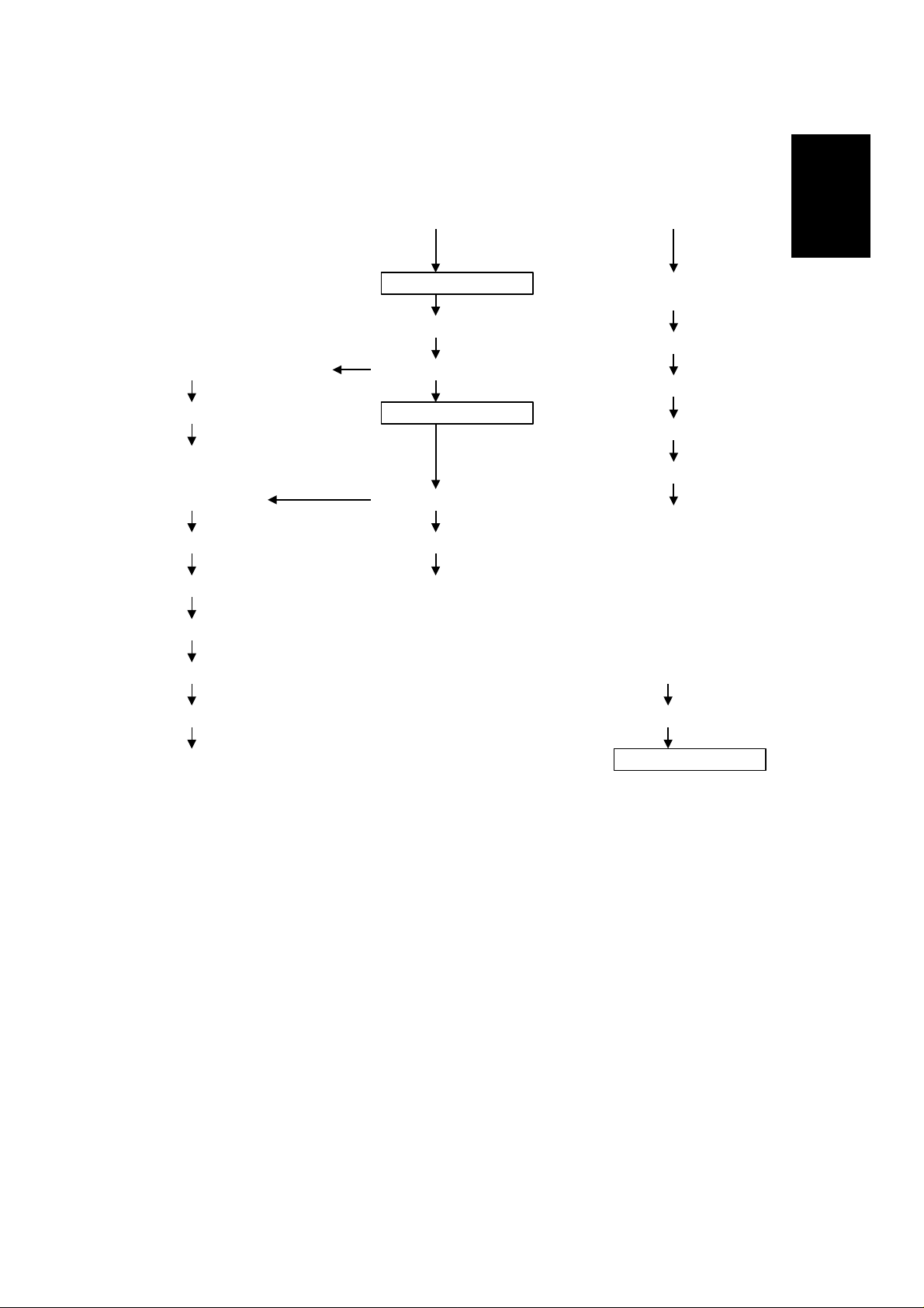
9.1 LENS POSITIONING
[A]
[D]
[C]
A203D501.img
[B]
Home Position (100%)
I
I
I
I
I
I
Enlargement Side Reduction Side
I
: Initialize
(100% → 141/129 %)
(141/129% → 71/65 %)
(71/65% → 93 %)
(93% → 71/65 %)
(71/65% → 141/129 %)
(141/129% → 122/121 %)
(122/121% → 100 %)
(100% → 71/65 %)
(71/65% → 100 %)
A203D502.wmf
The lens home position sensor [A] informs the main board when the lens is at
the full size position (home position). The main board determines the lens
stop position in reduction and enlargement modes by counting the number of
steps the motor makes with reference to the lens home position. When a new
reproduction ratio is selected, the lens [B] moves directly to the selected
magnification position.
The lens home position is registered each time the lens starts from or passes
through the lens home position sensor. As the lens moves from the
enlargement side to the reduction side, the sensor registers the home
position. This occurs when the actuator plate [C] enters the lens home
position sensor.
A small vibration can be observed when the lens moves through home
position from the enlargement side to the reduction side because the lens is
going in the wrong direction to register the home position. The lens
overshoots the home position by four pulses before going back to register the
home position.
The lens always stops while moving from left to right (as viewed from the
front) to minimize the error caused by mechanical play in the drive gears [D].
14
24 February 1997 OPTICS
9.2 BASE LAMP VOLTAGE IN MANUAL IMAGE DENSITY
MODE
SP48 sets the exposure lamp data for level 4 (Vo) of manual image density
mode. A value from 100 to 170 can be selected.
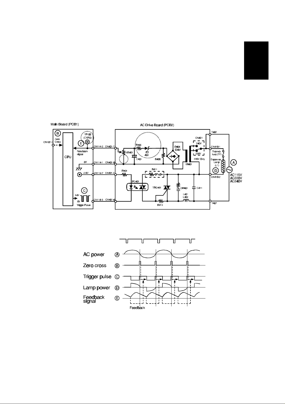
9.3 EXPOSURE LAMP CONTROL CIRCUIT
The circuit is different from A151 and A152 copiers at the indicated locations.
Copier
A202/A203
A203D504.wmf
A203D503.wmf
15
DEVELOPMENT 24 February 1997
10. DEVELOPMENT
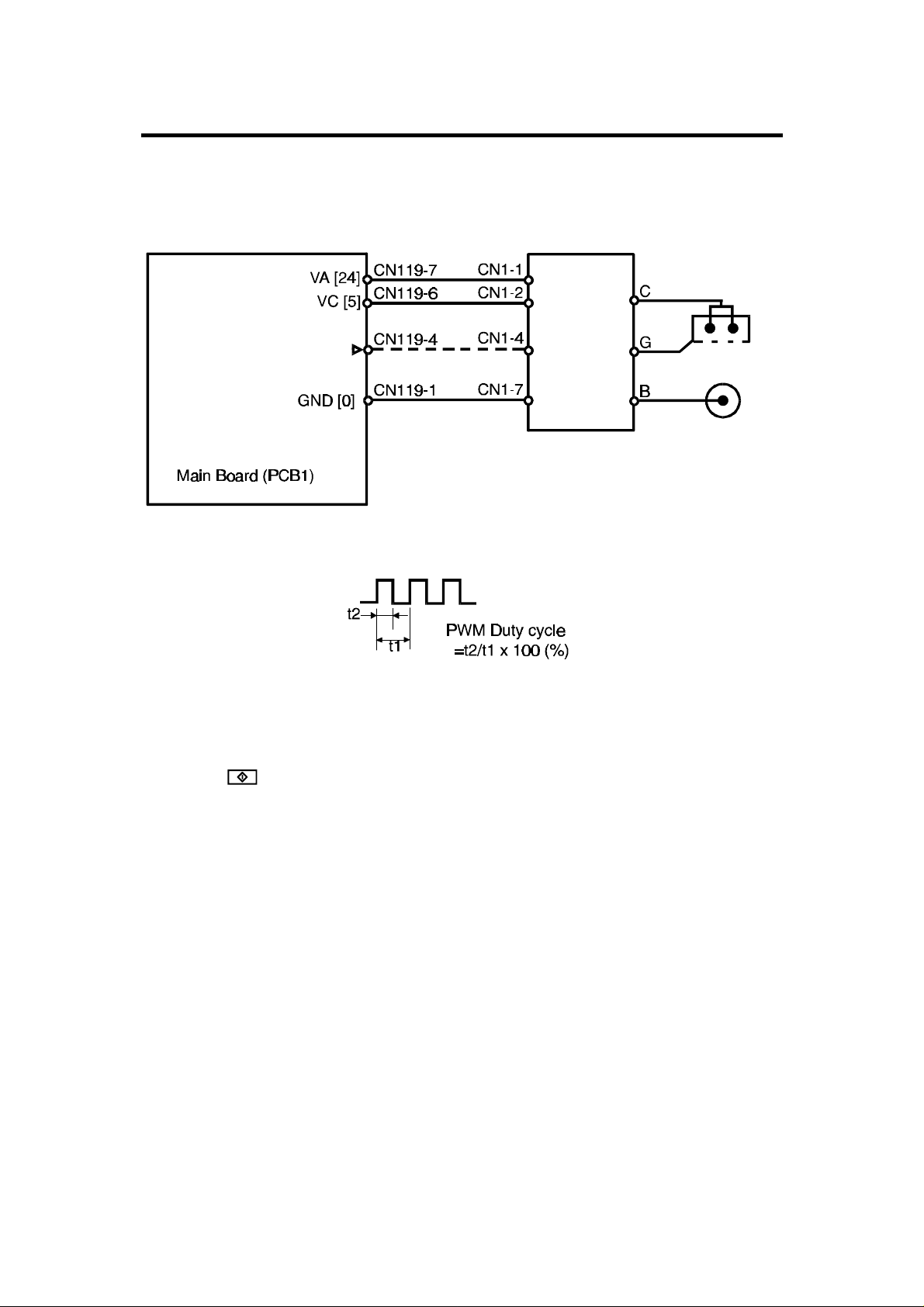
10.1 DEVELOPMENT BIAS CIRCUIT
Charge Corona
Power Pack -
Bias Trig (PWM) [▲0→0/5]
CC/Grid/Bias
(P1)
Grid
Development
Bias
A203D505.wmf
A203D506.wmf
The main board supplies +24 volts to the CC/Grid/Bias power pack at CN1-1.
When the key is pressed, the CPU starts sending the bias trigger pulses
to CN1-4. This energizes the development bias circuit within the
CC/Grid/Bias power pack, which applies a high negative voltage to the
development roller. The development bias is applied whenever the drum is
rotating.
The bias trigger pulse applied to CN1-4 is a pulse width modulated signal
(PWM signal). The width of the pulses controls the voltage level of the
development roller. As the width of the trigger pulses increase, the voltage to
the development roller also increases. The power pack is equipped with its
own feedback circuit to monitor the development bias voltage.
16

24 February 1997 TONER DENSITY DETECTION AND TONER SUPPLY
11. TONER DENSITY DETECTION AND TONER
SUPPLY
11.1 ID Sensor Control Circuit
This circuit is different from A151 and A152 copiers at the indicated location.
A203D509.wmf
Copier
A202/A203
17
 Loading...