

Page 1
Technical Bulletin No. RTB-001
SUBJECT: Service Manual Correction DATE: April 30, ’95
PAGE: 1 of 1
PREPARED BY: S. Hizen
CHECKED BY: M. Iwasa
CLASSIFICATION:
Action Required
Troubleshooting
Retrofit Information
User-Code 0 (U-0)
The User-code 0 (U-0) is missing in the code section of your service manual page 4-24.
Please add the User-code 0 in your service manual.
U-0:
The first scanner may accidentally move away from its home position during transportation
/ location change of the machine. If the main switch is turned on under this condition, U-0
appears.
Solution:
Turn the main switch off and on to eliminate the U0 code.
Revision of service manual
Information only
Other
FROM: 2nd Technical Support Section
MODEL:
Robin
NOTE: U-0 is different from E21/E22. The scanner home position sensor has no problem
for U-0, while the sensor may be defective for E21/E22.
Page 2
Technical Bulletin No. RTB-002
SUBJECT: Upper Unit Opening Problem DATE:May 15, ’95
PAGE: 1 of 5
PREPARED BY: S. Hizen
CHECKED BY: M. Iwasa
CLASSIFICATION:
Action Required
Troubleshooting
Retrofit Information
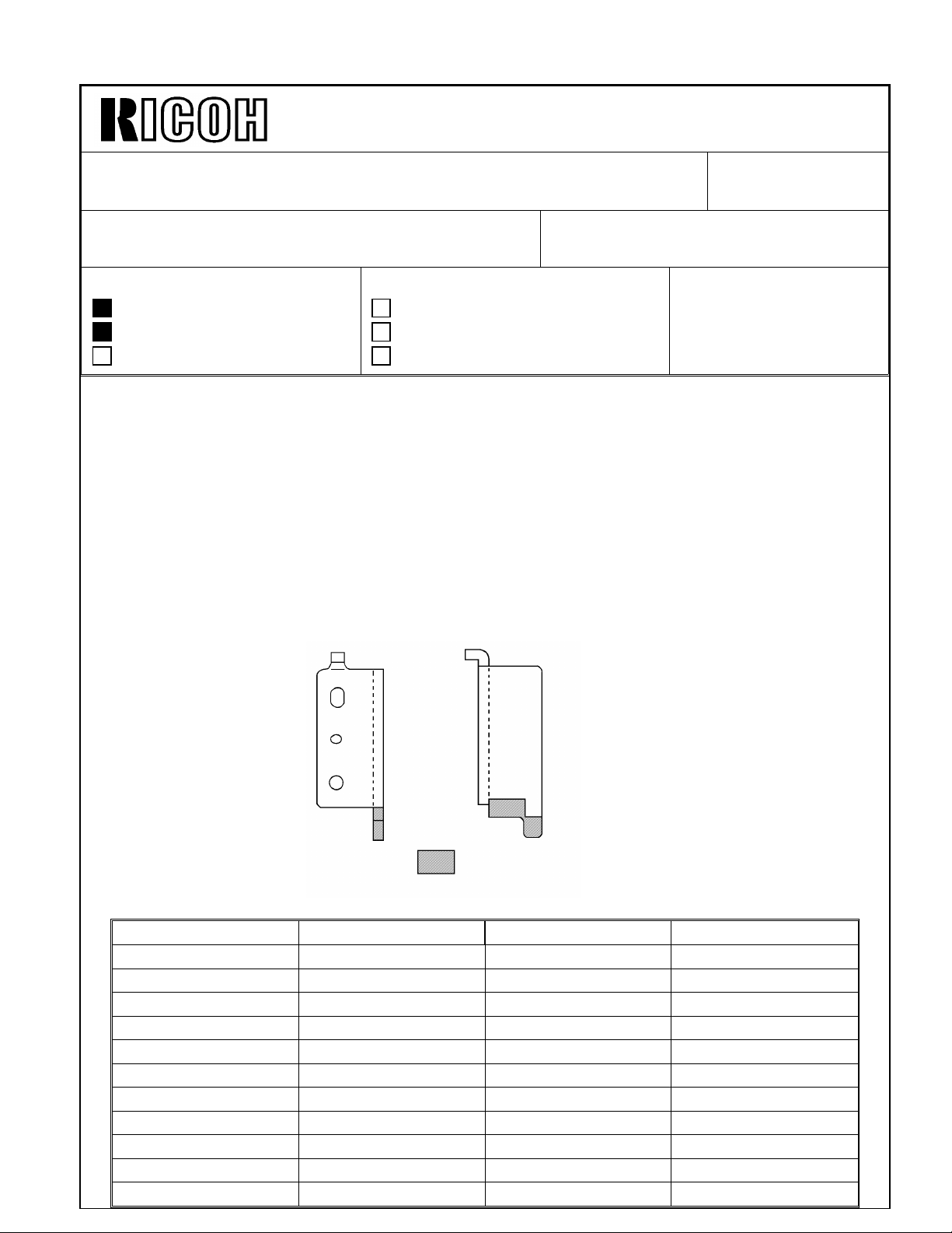
- Problem When the upper unit without the document feeder is released, it tends to open very
abruptly.
- Cause The torsion spring force is too strong.
- Temporary countermeasure for the production machines To reduce the torsion force, parts of the front and rear angle brackets which support the
torsion spring have been cut off as shown:
Revision of service manual
Information only
Other
FROM: 2nd Technical Support Section
MODEL:
Robin (A151 / A152)
Part cut off
The cut-in serial numbers for this modification are as follows:
Machine Code Cut-in Serial Number Machine Code Cut-in Serial Number
A151 - 10 26740900 01 A152 - 10 26940900 01
A151 - 15 1A240900 01 A152 - 15 1A340900 01
A151 - 16 From 1st Production A152 - 16 From 1st Production
A151 - 17 A3604092 283 A152 - 17 A36140 90001
A151 - 22 26641000 01 A152 - 22 26840900 01
A151 - 24 From 1st Production A152 - 24 From 1st Production
A151 - 25 26641000 89 A152 - 25 26840902 16
A151 - 26 3F21040001 A152 - 26 3F30940001
A151 - 27 A3604100 001 A152 - 27 A36140 91301
A151 - 28 From 1st Production A152 - 28 From 1st Production
A151 - 29 A3604103 600 A152 - 29 A36140 92170
Page 3
Technical Bulletin No. RTB-002
[A]
SUBJECT: Upper Unit Opening Problem DATE: May 15, ’95
PAGE: 2 of 5
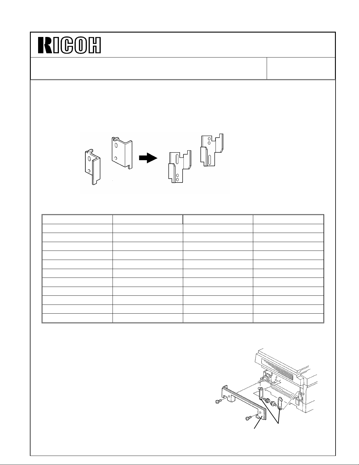
- Permanent countermeasure for the production machines To make it possible to adjust the force of the upper unit opening in the field, the
configurations of the front and rear angle brackets have been changed as shown.
Old
P/N A0771098
P/N A0771197
(Torsion Bar
Angle - Front)
The Cut-in serial numbers for this modification are as follows:
Machine Code Cut-in Serial Number Machine Code Cut-in Serial Number
A151 - 10 26750300 01 A152 - 10 26950200 01
A151 - 15 1A250300 01 A152 - 15 1A350200 01
A151 - 16 2675030051 A152 - 16 ---A151 - 17 A3605030 154 A152 - 17 A36150 30945
A151 - 22 26650200 01 A152 - 22 26850300 01
A151 - 24 ---- A152 - 24 ---A151 - 25 26650201 16 A152 - 25 26850301 21
A151 - 26 3F20350001 A152 - 26 3F30350001
A151 - 27 A3605030 001 A152 - 27 A36150 30001
A151 - 28 ---- A152 - 28 ---A151 - 29 A3605030 754 A152 - 29 A36150 32090
(Torsion Bar
Angle - Rear)
New
P/N A1521198
(Torsion Bar Angle Bracket-Rear)
P/N A15211 97
(Torsion Bar Angle (S/Ns of Dec. production
unit will be put in) - Front)
- How to adjust the force of the upper unit torsion spring -
1. Make sure that the main switch is turned off and
the power supply cord is unplugged.
2. Remove the platen cover or DF.
3. Open the front cover.
4. Remove the following covers and units.
• Development unit
• Upper rear cover
• Upper left cover [A]
5. Remove the front and rear upper unit stoppers [B] (1 screw each).
[B]
Page 4

Technical Bulletin No. RTB-002
Stronges t
Setting
A
•Screw
SUBJECT: Upper Unit Opening Problem DATE: May 15, ’95
PAGE: 3 of 5
6. Open the upper unit gently while holding it until the upper unit stops at the 90° position
as shown.
7. Remove the inner cover [D] (2 screws).
8. Adjust the force of the
torsion spring as
follows:
A
•Screw•Screw•Screw
A
Front
B
C
B
Factory
Setting
Torsion
Spring
- Factory Setting -
- Strongest Setting -
• Remove screw C
on both sides
• Loosen screw A
on both sides
• Shift the
adjusting bracket
toward the
torsion spring.
• Tighten screws
on both sides in
positions B and A.
Factory
Setting
Torsion
Spring
C
Rear
B
B
A
C
Stronges t
Setting
C
Page 5

Technical Bulletin No. RTB-002
•Screw
Rear
SUBJECT: Upper Unit Opening Problem DATE: May 15, ’95
PAGE: 4 of 5
Front
- Factory Setting B
A
A
B
C
- Strongest Setting -
Remove the adjusting
bracket (2 screws on
each side)
• Rotate the
bracket 180°
and install it
using holes A
and C.
C
•Screw
•Screw
C
A
B
B
A
A
C
- Factory Setting -
- Weak Setting -
• Remove the
adjusting
bracket (2
screws on each
side).
• Rotate the
bracket 180°
and install it
using holes B
and A.
A
•Screw
C
B
B
B
C
A
C
C
A
B
Page 6

Technical Bulletin No. RTB-002
[A]
SUBJECT: Upper Unit Opening Problem DATE: May 15, ’95
PAGE: 5 of 5
- Countermeasure for the field machines For field machines, we have prepared the following plate as a countermeasure part to add
weight to the upper unit.
P/N A1519900 Plate – 3.9 x 75 x 320 mm
Please install two of the above plates on the machines as described in the following
procedure:
- Installation Procedure -
1. Open the upper unit while holding on to it.
2. Remove the right cover [A] (2 screws).
3. Clean the right development stay [B] with alcohol.
4. Peel off the seal from the plate [C] and stick the plate on the right development stay.
5. Clean the surface of the plate with alcohol.
6. Stick the second plate [D] onto the first plate.
7. Reassemble the machine.
[C]
[B]
[C]
[D]
Page 7

REVISED ON DECEMBER 15, ’95 : Revised
Technical Bulletin No. RTB-003
SUBJECT: Energy Star DATE:September
30, ’95
PAGE: 1 of 4
PREPARED BY: N. Kaiya
FROM: 2nd Technical Support Section
CHECKED BY: M. Iwasa
CLASSIFICATION:
Action Required
Troubleshooting
Retrofit Information
Revision of service manual
Information only
Other
MODEL:
Robin
-10, -15, -17 only
This RTB explains the modifications made to meet the Energy Star specifications.
With this modification, to conserve energy, the copier automatically turns off 30 minutes
after the last copying job has been completed.
The details of the machine operation can be found on pages 3 to 4 of this RTB.
Auto Off Mode
To automatically turn off the copier, a new type of main switch with an incorporated coil
is used. When the CPU drops CN126-1 from +24V to 0, the main switch contact is
opened. The P to P wiring diagram and connector layout are shown below.
TO T402
TO T401
Co
Main Switch
DC Harness
To Safety Switch (SW2)
Main Control Board
CN126-1
CN126-2
Main Control Board
[ 24]Main Switch
[24]VA
Harness
Main Switch
Page 8

REVISED ON DECEMBER 15, ’95 : Revised
Technical Bulletin No. RTB-003
SUBJECT: Energy Star DATE:September
30, ’95
PAGE: 2 of 4
SP Mode
The following two modes have been newly provided.
Mode No. Function Settings
Auto off time can be selected 0 : 30 minutes (default)
1 : 15 minutes
SP14
SP9-7
The auto off time can also be selected by the customer.
Please refer to page 3 of this RTB for the procedure.
Output check for the main switch
(the machine will turn off)
2 : 1 hour
3 : 1.5 hours
4 : 2 hours
Instruction Sheet
An additional explanation sheet has been added to the operating instructions booklet.
Please refer to pages 3 and 4 of this RTB for the contents of this sheet. The Energy
Saver Mode described on the second page of this instruction sheet is the Auto Energy
Saver Mode originally available with this copier.
*
Page 9

REVISED ON DECEMBER 15, ’95 : Revised
Technical Bulletin No. RTB-003
SUBJECT: Energy Star DATE:September
30, ’95
PAGE: 3 of 4
*
Page 10

REVISED ON DECEMBER 15, ’95 : Revised
Technical Bulletin No. RTB-003
SUBJECT: Energy Star DATE:September
30, ’95
PAGE: 4 of 4
 Loading...