

Page 1

DOCUMENT FEEDER
(Machine Code: A662)
Page 2

24 February 1997 SPECIFICATIONS
1. SPECIFICATIONS
Original Size: Maximum: A3 or 11" x 17"
Minimum: A5 Lengthwise or 51/2" x 81/2"
Original Weight: 52 to 105 g/m2 (14 to 28 lb)
Original Feed: Automatic Feed - ADF mode
Semi-automatic Feed - SADF mode
Original Tray Capacity: 30 sheets - 80 g/m2 (20 lb)
Original Set: Face up, first sheet on top
Original Separation: Feed roller and friction belt
Original Transport: One flat belt
Copying Speed: 15 copies/minute
(A4 lengthwise or 81/2" x 11" lengthwise)
Power Consumption: 45 W
Dimensions (W x D x H): 590 x 443 x 87.5 mm (23.3" x 17.5" x 3.4")
(Not including the original table)
Weight: Approximately 7 kg (15.5 lb)
• Specifications are subject to change without notice.
Option
A662-1
Page 3
COMPONENT LAYOUT 24 February 1997
2. COMPONENT LAYOUT
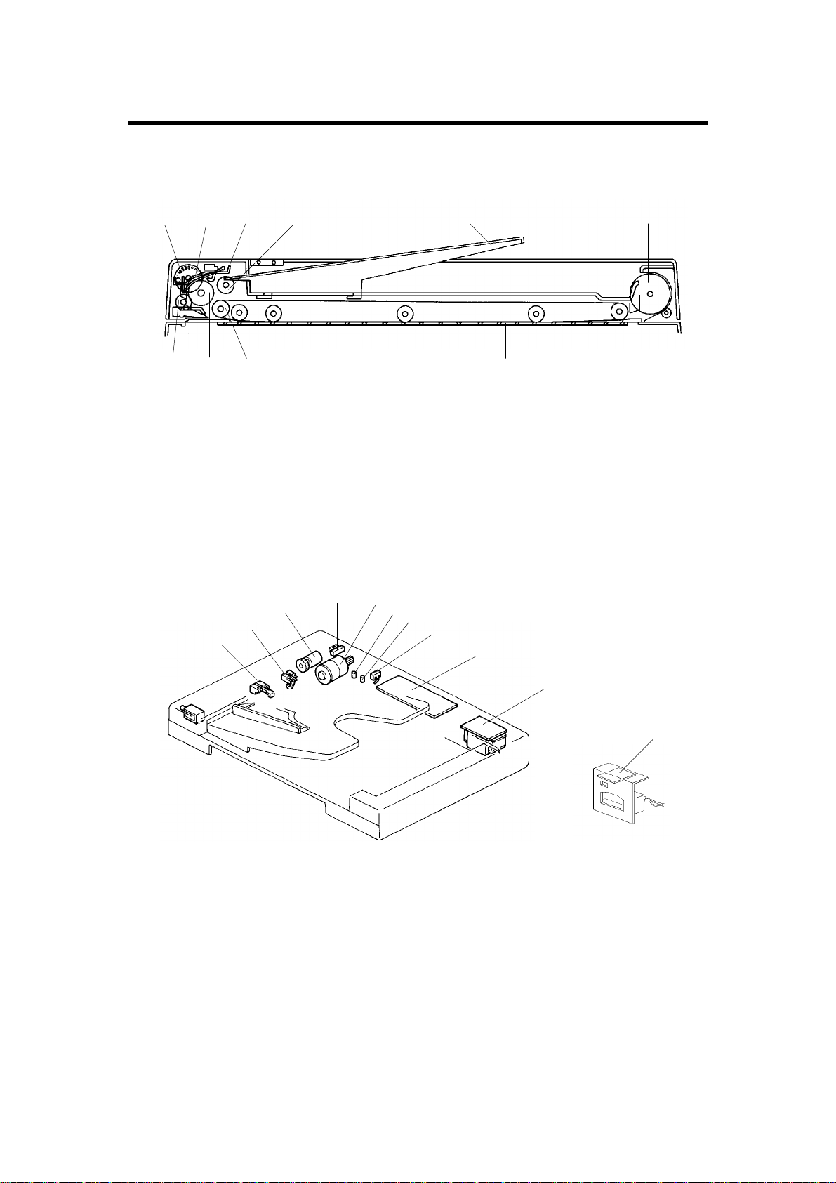
2.1 MECHANICAL COMPONENTS
1 2 3 4 65
1. Pulse Generator Disk
2. Friction Belt
3. Pick-up Lever
4. Pick-up Roller
5. Original Table
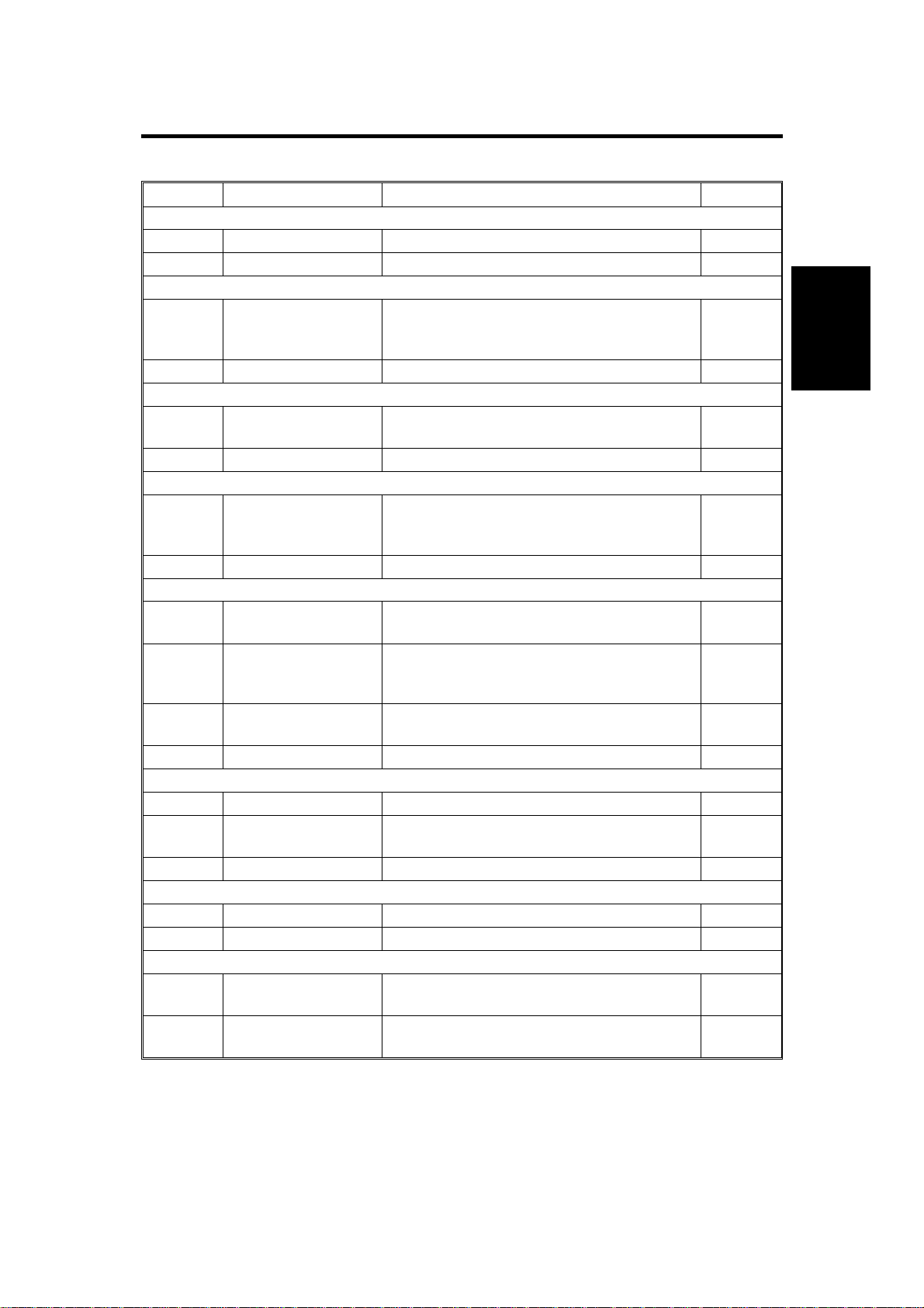
2.2 ELECTRICAL COMPONENTS
4
5
3
2
1
6
7
8
78910
6. Exit Roller
7. Transport Belt
8. Transport Belt Roller
9. Feed Roller
10. Relay Roller
9
10
11
A662V500.img
12
1. Pick-up Solenoid
2. Registration Sensor
3. Original Set Sensor
4. Feed Clutch
5. Pulse Generator Sensor
6. DF Motor
A662-2
A662V501.img
A662V502.img
7. Insert Original Indicator
8. SADF Indicator
9. Lift Switch
10. DF Main Board
11. DF Transformer
12. DF Interface Board
Page 4
24 February 1997 ELECTRICAL COMPONENT DESCRIPTIONS
3. ELECTRICAL COMPONENT DESCRIPTIONS
Symbol Name Function Index No.
Motor
M1 DF Motor Drives all the document feeder components. 6
Solenoid
Pick-up Solenoid Energizes to press the pick-up lever against
SOL1
Clutch
CL1
Switch
SW1
Feed Clutch Turns on to transmit main motor rotation to
Lift Switch Informs the CPU when the DF is lifted and
the stack of originals in preparation for
original feed-in.
the feed roller.
also serves as the misfeed reset switch for
the DF.
1
4
9
Option
Sensors
S1
S2
S3
Printed Circuit Board
PCB1 DF Main Board Controls all DF functions. 10
PCB2
Transformer
TR1 DF Transformer Steps down the wall voltage to 25 volts ac. 11
LEDs
LED1
LED2
Pulse Generator
Sensor
Original Set Sensor Informs the copier CPU that originals have
Registration Sensor Sets original stop timing and checks for
DF Interface Board Interfaces between the copier main board
SADF Indicator Informs the operator that the SADF mode is
Insert Original
Indicator
Supplies timing pulses to the DF main board.
been placed and causes the Insert Original
indicator to go out.
original misfeeds.
and the DF.
available.
Turns off when the originals are inserted into
the original table.
5
3
2
12
8
7
A662-3
Page 5
POWER DISTRIBUTION 24 February 1997
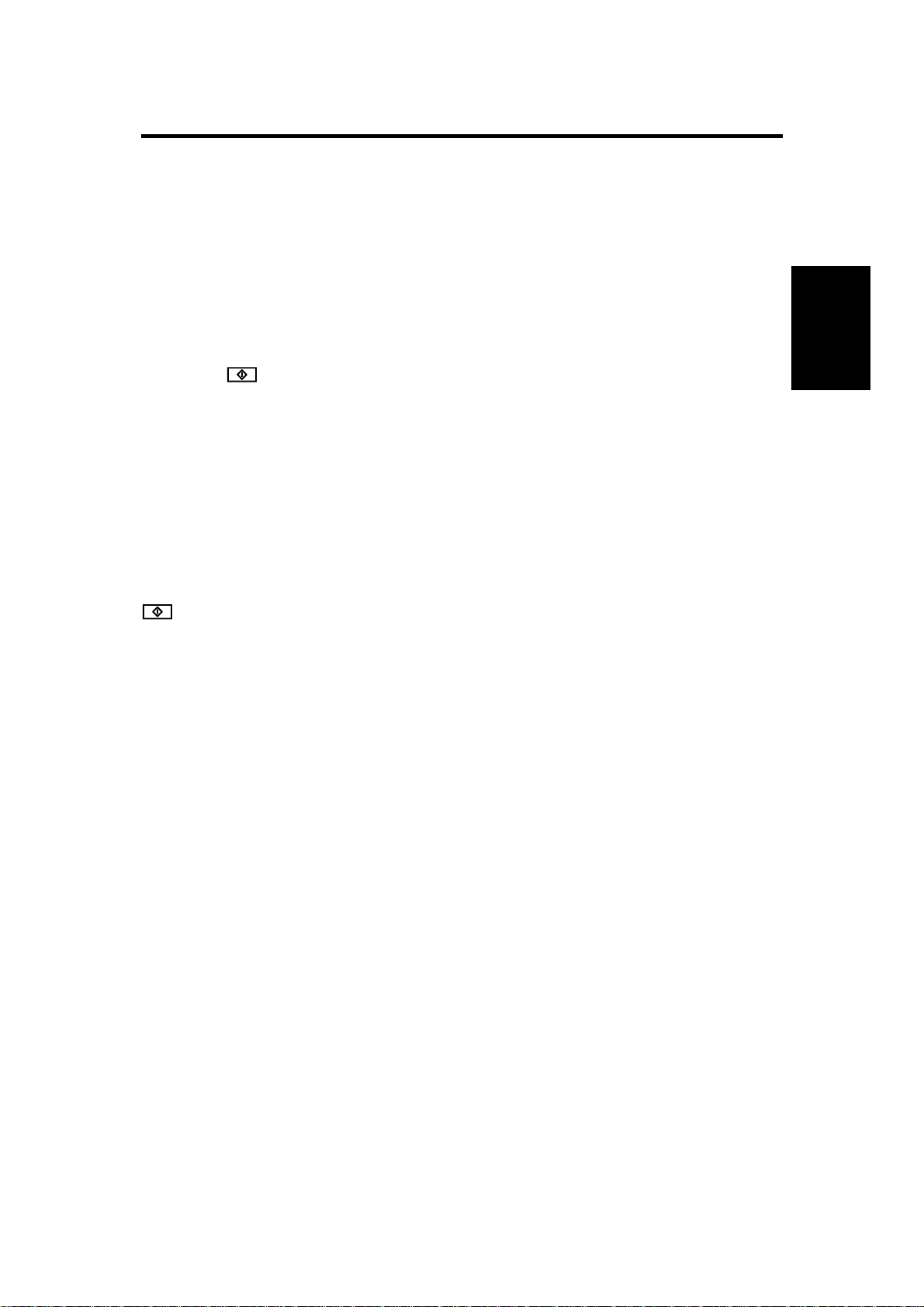
4. POWER DISTRIBUTION
A662D500.wmf
The document feeder uses two dc power levels: +24 volts, and +5 volts.
When the main switch is turned on, the DF transformer receives the wall
outlet ac power through the ac drive board and outputs 25 volts ac to the DF
main board. Then, the dc power supply circuit on the DF main board converts
the 25 volts ac input to +24 volts and +5 volts.
+24 volts is used by the DF motor, the pick-up solenoid, and the feed clutch.
+5 volts is used by other electrical components.
A662-4
Page 6
24 February 1997 BASIC OPERATION
5. BASIC OPERATION
When the main switch is turned on, the DF CPU sends the "DF installed"
signal to the copier CPU. Receiving this signal, the copier CPU recognizes
that the document feeder is installed and sends the "DF confirmed" signal to
the DF CPU.
When originals are placed on the original table, the Insert Original indicator
turns off and the DF CPU sends the "original set" signal to the copier CPU to
inform that the originals have been set.
When the key is pressed, the copier CPU sends the "feed-in" signal to
the document feeder. On receipt of this signal, the DF CPU energizes the DF
motor, then the pick-up solenoid and feed clutch to feed in the bottom sheet
of the original stack onto the exposure glass. The pick-up solenoid and the
feed clutch remain energized until the original’s leading edge reaches the
registration sensor. The DF motor turns off shortly after the original’s trailing
edge passes the registration sensor. Then, the DF motor pauses and
reverses for a moment to align the edge of the original with the scale.
Option
Then the scanner starts to move (scanner start timing does not depend on
the progress of the original through the DF; it starts at a fixed time after the
key is pressed). When the scanner reaches the return position, the
copier CPU sends the "original change" signal to the DF CPU in order to feed
out the current original and feed in the next original.
A662-5
Page 7
INTERFACE CIRCUIT 24 February 1997
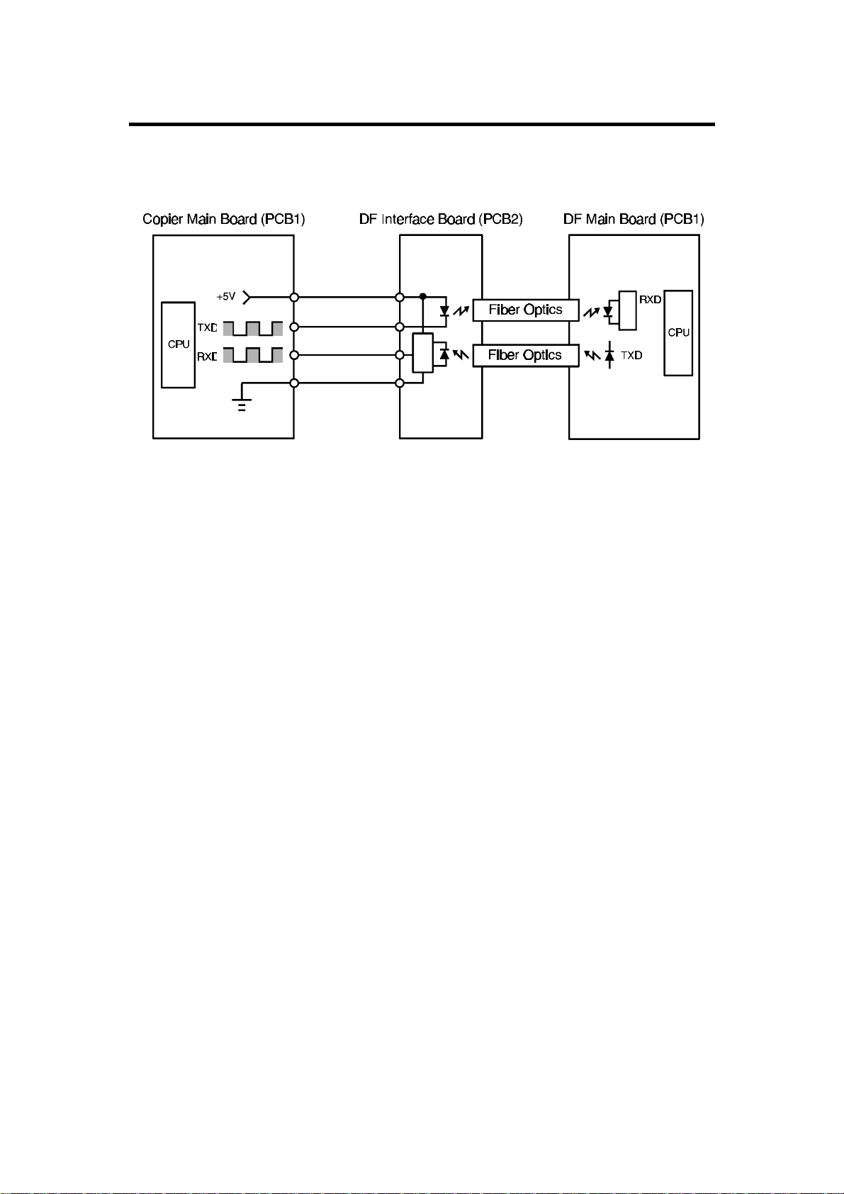
6. INTERFACE CIRCUIT
A662D509.wmf
The copier CPU and the DF CPU communicate via the interface board using
fiber optics. The interface board changes the optical signals to electrical
signals (and vice versa).
A662-6
Page 8

24 February 1997 ORIGINAL FEED
7. ORIGINAL FEED
7.1 ORIGINAL PICK-UP MECHANISM
[B]
[C]
[A]
Option
[D]
A662D502.img
After setting the originals on the original table, the originals contact the feeler
[A] of the original set sensor and cause the feeler to move out of the sensor.
The DF CPU then sends the original set signal to the copier CPU to inform it
that the document feeder will be used. When the key is pressed, the
pick-up solenoid [B] is energized. The original stack is then pressed between
the pick-up lever [C] and pick-up roller [D]. The rotation of the pick-up roller
advances the bottom original.
A662-7
Page 9

ORIGINAL FEED 24 February 1997
7.2 ORIGINAL SEPARATION MECHANISM
[B]
[D]
[C]
[A]
[E]
[C][D][B]
A662D503.img
[E]
[A]
A662D504.img
The feed roller [A] and the friction belt [B] are used to feed in and separate
the originals [C]. Only the bottom original is fed because the friction belt
prevents any other originals from feeding.
Original feed starts when the pick-up lever [D] presses the original stack and
the pick-up roller [E] advances the bottom original of the stack. The feed
roller moves the original past the friction belt because the driving force of the
feed roller is greater than the resistance of the friction belt. The friction belt
prevents multiple feeds because the resistance of the friction belt is greater
than the friction between original sheets.
A662-8
Page 10

24 February 1997 ORIGINAL FEED
7.3 ORIGINAL FEED-IN MECHANISM
[C]
[E]
[G]
[A]
[D]
[B]
[F]
A662D505.img
The DF motor [A] drives the feed roller [B], the pick-up roller [C], the relay
rollers [D], and the transport belt roller [E] via timing belts and a gear train.
The feed roller and the pick-up roller are controlled by the feed clutch [F], but
the relay rollers and the transport roller are directly driven by the DF motor.
The idler rollers [G] on the feed roller shaft are free from the shaft.
Option
When the key is pressed, the DF motor is energized and the relay rollers
and transport belt roller start turning. 100 milliseconds after the DF motor
starts turning, the pick-up solenoid and the feed clutch are energized. The
pick-up and feed rollers then start turning and carry the original between the
relay rollers and the idler rollers. The pick-up solenoid and the feed clutch are
de-energized when the original’s leading edge passes through the
registration sensor.
The DF motor remains energized to deliver the original to the exposure glass
until a certain number of pulses (10 to 25 pulses) after the original’s trailing
edge passes through the registration sensor. Then, the DF motor pauses and
reverses for 15 pulses to align the edge of the original with the scale.
To feed the second original, the DF motor starts rotating when the scanner
reaches the return position. (The copier CPU sends the original change
signal to the DF CPU.) At this time, the transport belt starts carrying the first
original on the exposure glass to the exit roller. The timing for when the
pick-up solenoid and the feed clutch are energized for the second original
depends on the length of the first original detected by the registration sensor.
A662-9
Page 11

ORIGINAL FEED 24 February 1997
7.4 ORIGINAL FEED-OUT MECHANISM
[D]
[C]
[A]
[B]
A662D506.img
The exit rollers are driven by the DF motor through a gear train, the transport
belt roller, the transport belt [A], the transport belt roller [B], and the exit roller
drive belt [C]. When the DF CPU receives the original change signal from the
copier CPU, the DF motor starts turning. The transport belt carries the
original to the exit rollers [D] and the exit rollers take over the original
feed-out.
A662-10
Page 12

24 February 1997 ORIGINAL FEED
7.5 DF MOTOR CIRCUIT
Option
A662D507.wmf
The DF motor is a 24 volt dc motor. When the CPU receives the feed signal
from the copier, the CPU outputs the ON signal and the Forward signal to the
gate IC. On receipt of the forward signal from the gate IC, the driver IC
outputs 24 volts to CN117-1 and 0 volts to CN117-2. This causes the DF
motor to start turning in the forward direction.
Within 10 to 25 pulses after the original’s trailing edge passes through the
registration sensor, the CPU stops sending the ON signal and the Forward
signal. The DF motor stops turning. Then the CPU outputs the ON signal and
the reverse signal for 15 pulses. Then the driver IC outputs 0 volts to
CN117-1 and +24 volts to CN117-2 to reverse the DF motor.
A662-11
Page 13

ORIGINAL FEED 24 February 1997
7.6 ORIGINAL FEED AND MISFEED DETECTION TIMING
A662D508.wmf
The above chart shows the original feed timing for A4 lengthwise or 8.5" x
11" originals, and the misfeed detection timing.
The registration sensor is used for misfeed detection. If the DF CPU detects
a misfeed, the DF CPU lights the Original Misfeed indicator and sends the
original misfeed signal to the copier CPU. Then the copier CPU lights the
Check Paper Path and Misfeed Location (J0) indicators on the operation
panel.
When the main switch is turned on, the DF CPU checks the registration
sensor output for initial original misfeed.
During original feed-in, the DF CPU performs two types of original misfeed
detection:
1. Whether the registration sensor is actuated within 500 milliseconds after
the pick-up solenoid and the feed clutch turn on.
2. Whether the original has passed through the registration sensor 1,500
milliseconds after the registration sensor has been actuated.
A662-12
Page 14

24 February 1997 SERVICE TABLES
8. SERVICE TABLES
8.1 DIP SWITCHES
DPS 1
1 2 3 4
0 0 0 0 Normal Setting
1 0 0 1 Free Run
0 0 1 1 Solenoid Test
1 1 0 1 Motor Test
1 1 1 1 All Indicators On
Function
NOTE: All the functions are executed when the DF is closed.
8.2 VARIABLE RESISTORS
VR No. Function
VR1 Adjusts registration
8.3 FUSE
Fuse No. Rating Blown Fuse Condition
F1 F2 A/250 V The DF will not operate.
Option
A662-13
Page 15

REPLACEMENT AND ADJUSTMENT 24 February 1997
9. REPLACEMENT AND ADJUSTMENT
9.1 TRANSPORT BELT REPLACEMENT
[A]
[B]
A662R500.img
[E]
[I]
[F]
[G]
[D]
[H]
A662R501.img
1. Turn off the main switch.
2. Remove the original table [A].
3. Remove the DF [B] from the copier (2 knob screws, 1 power supply cord,
and 1 optics harness).
4. Remove the grip guide [C] (2 screws).
5. Remove the transformer cover [D] (3 screws), DF motor cover [E]
(4 screws) and main board cover [F] (2 screws).
[C]
6. Remove the transport belt assembly [G] (5 screws and 1 drive belt [H]).
NOTE: When installing the transport belt assembly, make sure that the
positioning pin [I] fits into the DF frame.
A662-14
Page 16

24 February 1997 REPLACEMENT AND ADJUSTMENT
[A]
[B]
A662R502.img
Option
7. Remove the transport roller holder [A] (1 screw, 1 snap ring and 1
bearing).
8. Pull out the transport belt [B].
NOTE: After reinstalling the transport belt, make sure that the bushings
of the transport rollers set correctly and the transport belt turns
smoothly.
A662-15
Page 17

REPLACEMENT AND ADJUSTMENT 24 February 1997
9.2 FEED-IN UNIT REMOVAL
[C]
[A]
[B]
A662R503.img
1. Turn off the main switch.
2. Remove the transport belt assembly. (See Transport Belt Replacement.)
3. Remove the left hinge bracket [A] (4 screws and 1 connector).
4. Disconnect five connectors from the main board [B] (CN111, CN113,
CN115, CN116 and CN117).
5. Remove the feed-in unit [C] (5 screws).
NOTE: When reinstalling the feed-in unit, the harness must be
positioned underneath the right hinge bracket.
A662-16
Page 18

24 February 1997 REPLACEMENT AND ADJUSTMENT
9.3 PICK-UP ROLLER REPLACEMENT
[D]
[C]
Option
[A]
[B]
A662R504.img
1. Turn off the main switch.
2. Remove the feed-in unit. (See Feed-in Unit Removal.)
3. Remove the DF motor [A] (2 screws and 1 timing belt [B]).
4. Remove the pick-up roller [C] (2 E-rings and 1 bushing) from the shaft [D].
A662-17
Page 19

REPLACEMENT AND ADJUSTMENT 24 February 1997
9.4 FEED ROLLER REPLACEMENT
[H]
[E]
[I]
[G]
[B]
[F]
[C]
[A]
[D]
A662R505.img
1. Turn off the main switch.
2. Remove the feed-in unit. (See Feed-in Unit Removal.)
3. Remove the feed roller timing belt [A], feed roller gear [B] (1 E-ring and 1
spring pin [C]) and 1 bushing [D].
NOTE: Be careful not to lose the spring pin.
4. Slide the feed roller shaft [E] towards the front and remove the feed clutch
[F] (1 E-ring and 1 connector).
5. Take out the feed roller shaft (1 spacer and 1 bushing ----- from the rear
side).
6. Remove the feed roller [G] from the shaft (3 idler rollers [H], 7 E-rings and
1 spring pin [I]).
NOTE: Be careful not to lose the spring pin.
A662-18
Page 20

24 February 1997 REPLACEMENT AND ADJUSTMENT
9.5 FRICTION BELT REPLACEMENT
[A]
Option
A662R507.img
1. Turn off the main switch.
[B]
[C]
A662R506.img
2. Remove the friction belt assembly [A] (1 screw).
3. Remove the friction belt [B] (2 springs, 1 pin).
NOTE: When installing the friction belt assembly, make sure the feed
roller [C] is set in the correct position. (See the illustration.)
A662-19
Page 21

REPLACEMENT AND ADJUSTMENT 24 February 1997
9.6 PICK-UP SOLENOID ADJUSTMENT
[F]
[E]
[B]
[C]
[A]
[D]
A662R508.img
1. Turn off the main switch.
2. Remove the feed-in unit. (See Feed-in Unit Removal.)
3. Loosen two screws [A] securing the pick-up solenoid [B].
4. Place a 1.2 mm thickness gauge [C] between the plunger and the
solenoid.
5. Turn the solenoid lever [D] clockwise until the plunger touches the
thickness gauge. Just at this point, tighten two screws.
6. Make sure that the pick-up lever [E] is touching the pick-up roller [F] when
the plunger is pushed. If not, repeat steps 3 to 5.
7. Reassemble the DF.
8. Turn on the main switch and check the original feed-in operation.
A662-20
 Loading...