

Page 1

IMPORTANT SAFETY NOTICES
PREVENTION OF PHYS ICAL INJURY
1. Before disassembling or asse mblin g pa rts of the copie r and perip herals,
make sure that the copier power cord is unplu gg ed.
2. The wall outlet should be near the copier an d easily accessible.
3. Note that the optio na l a nt i-con de nsation heaters are supplied wit h
electrical voltage even if the main switch is turned off .
4. If any adjustment or operat ion check ha s to be made with exterior covers
off or open while the main switch is turned on, kee p ha nds away from
electrified or mechanically drive n comp on ents.
5. The inside and the met al pa rts of the fusin g un it be come extremely hot
while the copier is operat ing . Be careful to avoid touching those
components with your bare hands.
6. When the development unit, cleaning unit, drum unit, or the DF is
removed from the machine, the upper unit becomes lighter. If th e up per
unit is released under this condition, it tends to open very abrupt ly. The
service engineer might be injured if he is leaning over the machine at this
time. Also, the machine might move due to the shock of the up pe r unit
opening abruptly. To avoid possib le inju ry o r machine damage, hold the
upper unit firmly when opening the unloaded upper unit.
7. Due to variation in the tolerance of the torsion springs, the upper unit
cannot be held at an angle of 16 deg rees by itself when the DF is
installed. To avoid possible injury, always use the upper unit stand to
keep the upper unit op en.
HEALTH SAFETY CONDITIONS
1. Never operate the copier without the ozon e filt er inst alle d.
2. Always replace the ozone filter at 80K copy intervals.
3. Toner and developer are non-to xic, bu t if you get eith er of them in your
eyes by accident, it may cause temp ora ry e ye disco mfo rt. Try to remove
with eye drops or flush with wat er as first aid. If un succe ssfu l, ge t med ical
attention.
©1994 By Ricoh Company Ltd. All right s reserved
Page 2

OBSERVANCE OF ELECTRICAL SAFETY STANDARDS
1. The copier and its peripherals must be insta lled and maintained by a
customer service represen tative who has completed the training course
on those models.
– CAUTION –
2. The RAM pack has a lithium battery which can explode if handled
incorrectly. Replace only with same RAM pa ck. Do not recharge, or
burn this battery. Used RAM pack must be handled in accord ance with
local regulations.
SAFETY AND ECOLOGICAL NOTES FOR DISP OS AL
1. Do not incinerate the toner cartridge or the used toner. Toner dust may
ignite suddenly when exposed to open flame.
2. Dispose of used tone r, developer, and organic photoconductors
according to local regulations. (These are non-toxic supplies.)
3. Dispose of replaced parts in acco rda nce with local regulations.
4. When keeping used lithium batteries (main control boards) in order to
dispose of them later, do not store mo re th an 100 batte ries (main control
boards) per sealed box. Storing larg er nu mbe rs or n ot sealing them apart
may lead to chemical reactions and heat build -up .
Page 3

SECTION 1
OVERALL MACHINE
INFORMATION
Page 4
24 June 1994 SPECIFICATIONS
1. SPECIFICATIONS
Configuration : Desk top
Copy Process: Dry electrostatic transfer system
Original Type: Sheet/Book
Original Alignment: Left center
Original Size: Maximum: A3/11" x 17" (lengthwise) – A152
copier
B4/10" x 14" (lengthwise) – A151
copier
Copy Paper Size: Maximum: B4/10" x 14" (lengthwise)
Minimum:
Paper Tray: A5/51/2" x 81/2" (lengthwise)
Bypass Feed: A6/51/2" x 81/2" (lengthwise)
Copy Paper Weight: Paper tray feed – 64 to 90 g/m2 (17 to 24 lb)
Bypass feed – 52 to 105 g/m2 (14 to 28 lb)
Reproduction Ratios: 2 Enlargement and 3 Reduction (A152 copie r only)
A4 Version Letter Version
Enlargement
Full size 100% 100%
Reduction
Zoom: From 61% to 141% in 1% steps
(A152 copier only)
Copying Speed: 13 copies/minute (A4 /81/2" x 11" lengthwise)
10 copies/minute (B4/81/2" x 14")
Warm-Up Time: 30 seconds (at 20°C/68°F)
First Copy Time: 9 seconds (A4/81/2" x 11" lengt hwise)
141%
122%
93%
82%
71%
129%
121%
93%
74%
65%
Copy Number Input: Number keys, 1 to 99
Manual Image Density
Selection:
7 steps
1-1
Page 5

SPECIFICATIONS 24 June 1994
Automatic Reset: 1 minute standard setting; can also be set to 3
minutes or no automatic reset.
Energy Saver Function: Automatic
Paper Capacity: Paper tray – 250 sheets
Bypass feed table – 1 she et
Toner Replenishment: Cartridge exchange (320 g/cartridge)
Copy Tray Capacity: 100 sheets (B4/10" x 14" or smaller)
Power Source: 110V / 60 Hz/ 15A (for Taiwan)
115V/ 60Hz/ 15A (for North America)
220V – 240V/ 50Hz/ 8A (for Europe)
220V/ 60Hz/ 8A (for Middle East)
220V/ 50Hz/ 8A (for Asia)
(Refer to the serial number plate (rating plat e) to
determine the power source required by the
machine.)
Power Consumption:
Noise Emission:
Dimensions:
Copier with platen cover and
copy tray
Copier with document feeder
and copy tray
Copier Only With DF
Maximum 1.4 kVA 1.5 kVA
Warm-up 620 VA (average) 640 VA (average)
Copy cycle 810 VA (average) 860 VA (average)
Ready 160 VA (average) 180 VA (average)
Copier Only With DF
Maximum 58 db 60 db
Copy cycle Less than 55 db Less than 55 db
Ready Less than 39 db Less than 39 db
Width Depth Height
713 mm (28.1") 592 mm (23.3") 400 mm (15.7")
713 mm (28.1") 592 mm (23.3") 463 mm (18.2")
1-2
Page 6

24 June 1994 SPECIFICATIONS
Weight: Copier only: 43 kg (94.8 lb)
With DF: 50 kg (110.2 lb)
Optional Equipment:
(Sales items)
Optional Equipment:
(Service items)
Document feeder (A152 copier only)
Key counter
Drum anti-condensation heater
Optics anti-condensation heater
Pre-transfer lamp
Optics cooling fan (for A151 copie r only)
• Specifications are subject to change witho ut notice.
1-3
Page 7
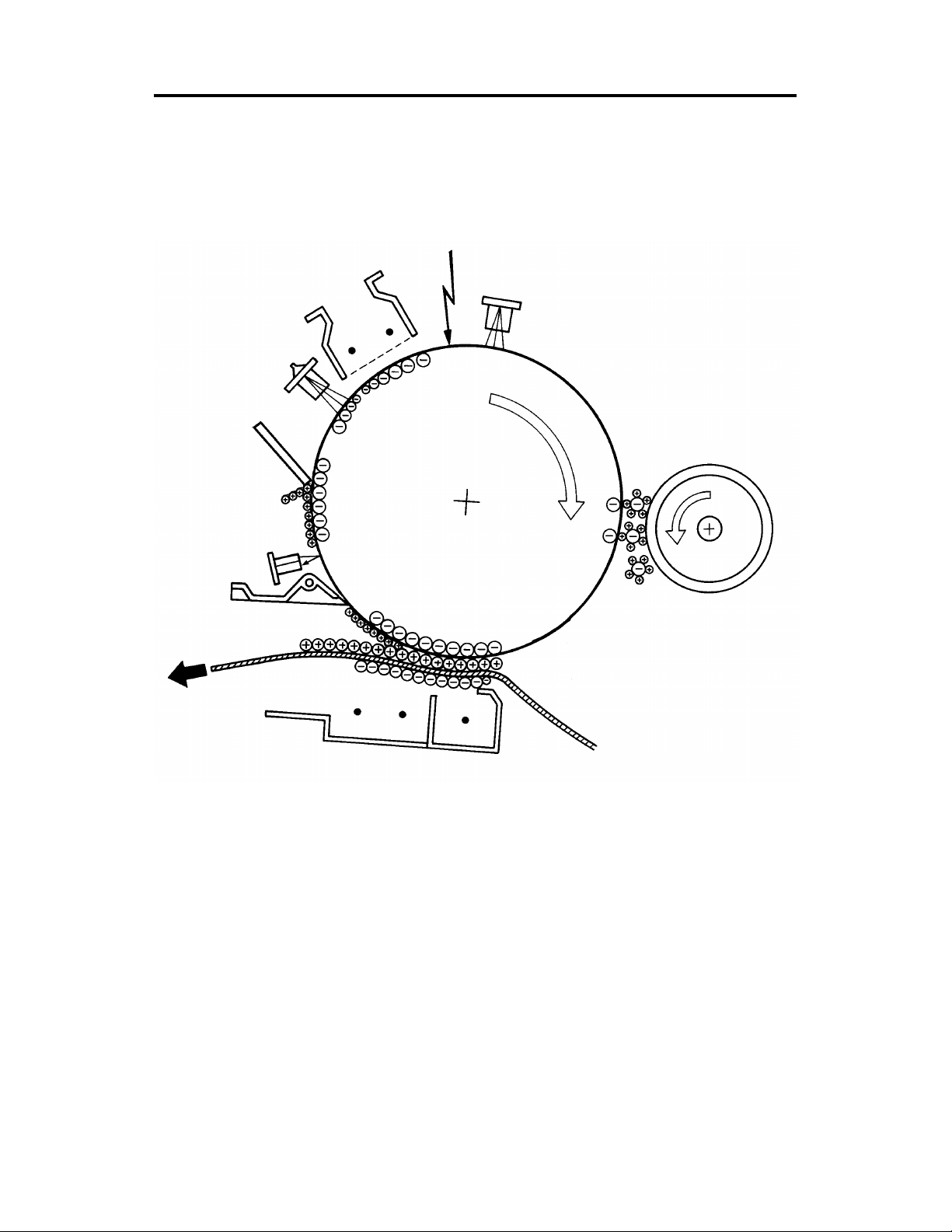
COPY PROCESSES AROUND THE DRUM 24 June 1994
2. COPY PROCESSES AROUND THE DRUM
2. EXPOSURE
1. DRUM CHARGE
3. ERASE
8. QUENCHING
4. DEVELOPMENT
7. CLEANING
6. PAPER
SEPARATION
5. IMAGE TRANSFER
1-4
Page 8

24 June 1994 COPY PROCESSES AROUND THE DRUM
1. DRUM CHARGE
In the dark, the charge corona unit gives a uniform negative charge to the organic
photoconductive (OPC) drum. The charge remains on the surface of the drum because the
OPC drum has a high electrical resistance in the dark.
2. EXPOSURE
An image of the original is reflected to the OPC drum surface via the optics assembly. The
charge on the drum surface is dissipated in direct proportion to the intensity of the reflected
light, thus producing an electrical latent image on the drum surface.
3. ERASE
The erase lamp illuminates the areas of the charged drum surface that will not be used for
the copy image. The resistance of the drum in the illuminated areas drops and the charge on
those areas dissipates.
4. DEVELOPMENT
Positively charged toner is attracted to the negatively charged areas of the drum, thus
developing the latent image. (The positive triboelectric charge is caused by friction between
the carrier and toner particles.)
5. IMAGE TRANSFER
Paper is fed to the drum surface at the proper time so as to align the copy paper and the
developed image on the drum surface. Then, a strong negative charge is applied to the back
side of the copy paper, producing an electrical force which pulls the toner particles from the
drum surface to the copy paper. At the same time, the copy paper is electrically attracted to
the drum surface.
6. PAPER SEPARATION
A strong ac corona discharge is applied to the back side of the copy paper, reducing the
negative charge on the copy paper and breaking the electrical attraction between the paper
and the drum. Then, the stiffness of the copy paper causes it to separate from the drum
surface. The pick-off pawl help to separate the paper from the drum.
7. CLEANING
The cleaning blade removes any toner remaining on the drum.
8. QUENCHING
Light from the quenching lamp electrically neutralizes the surface of the drum.
1-5
Page 9

COPY PROCESS CONTROL 24 June 1994
3. COPY PROCESS CONTROL
Image
Density
Control
Toner
Density
Detection
Residual
Voltage
(Vr)
Detection
Between
Copies
Grid Voltage
Standard image
density grid voltage
(–680 V)
+ + +
Drum residual voltage
(Vr) correction factor
(SP67)
+
Auto image density
level factor (SP34)
Standar d ID sensor
grid voltage
(–460 V)
+
Drum wear correction
factor (SP57)
Standar d ID sensor
grid voltage
(–460 V)
+
Drum wear correction
factor (SP57)
0 Volts (Fixed) Exposure lamp tu rns off –160 Volts (Fixed)
Exposure Lamp
Voltage
Base exposure lamp
voltage (Manual or ADS
mode) (SP48)
V
L correction factor
+
Reproduction ratio
correction factor (A152
copier on ly)
Same as image density
control
Same as image density
control
Development Bias
Voltage
Base bias voltage factor
(Manual or ADS mode
[SP34])
Image bias voltage
adjustme nt factor
(SP37)
+
Drum residual voltage
(Vr) correction factor
Note:
Base bias voltage at
manual ID level 7 can be
adjusted by SP50
Depends on I D sensor
bias setting (SP33)
Note:
For initial 499 copies
bias voltage is increased
by –20 volt s
0 Volts (Fixed) Full erase
+
Image bias voltage
adjustme nt factor
(SP37)
+
Drum residual voltage
(Vr) correction factor
Erase Lamp
Depends on
paper size
and
reproduction
ratio
ID sensor
pattern erase
(Vsg
detection:
Full erase)
(All LEDs ON)
Full erase
(All LEDs ON)
NOTE: The boxed items can be adjusted by SP mode.
1-6
Page 10
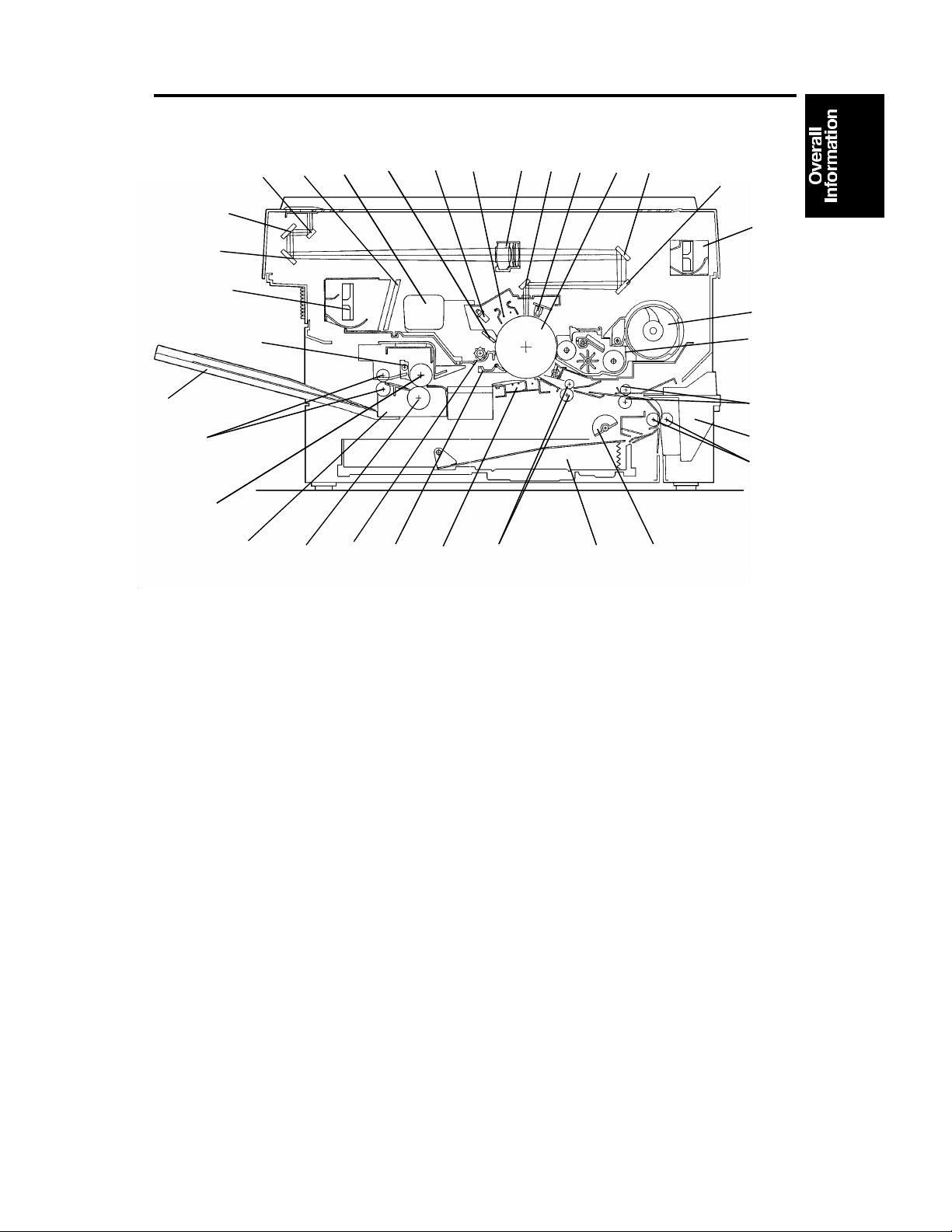
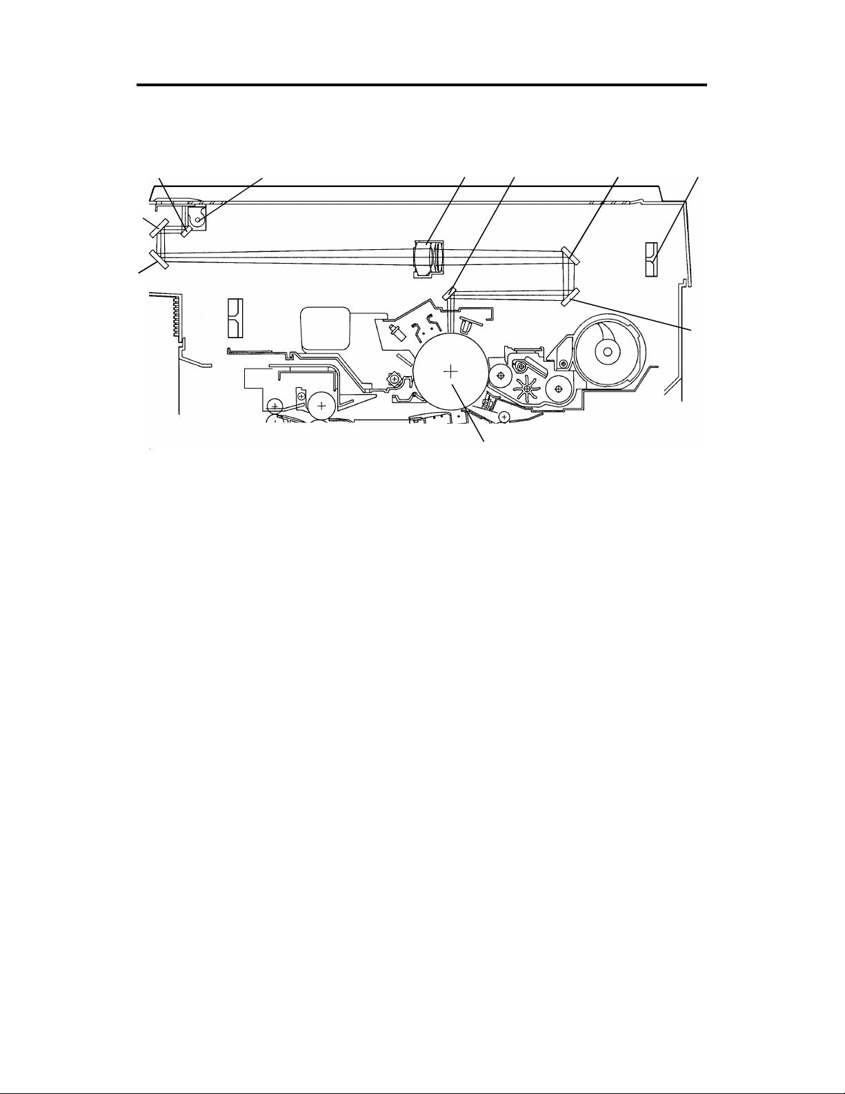
24 June 1994 MECHANICAL COMPONENT LAYOUT
4. MECHANICAL COMPONENT LAYOUT
11
10
9
14
15
13
16
17
18
19
21 22 23
20
24 25
26
27
28
29
12
30
31
32
33
8
7
6
5
4
3
2
1
1. Semicircular Feed Rollers
2. Paper Tray
3. Registration Rollers
4. Transfer and Separation
Corona Unit
5. Pick-off Pawl
6. Cleaning Unit
7. Pressure Roller
8. Fusing Unit
9. Hot Roller
10. Exit Rollers
11. Copy Tray
12. Hot Roller Strippers
13. Exhaust Blower Motor
14. 3rd Mirror
15. 2nd Mirror
16. 1st Mirror
17. Ozone Filter
18. Used Toner Tank
19. Cleaning Blade
20. Quenching Lamp
21. Charge Corona Unit
22. Lens
23. 6th Mirror
24. Erase Lamp
25. Drum
26. 4th Mirror
27. 5th Mirror
28. Optics Cooling Fan Motor
(A152 Copier only)
29. Toner Supply Unit
30. Development Unit
31. 2nd Relay Rollers
32. By-pass Feed Table
33. 1st Relay Rollers
1-7
Page 11
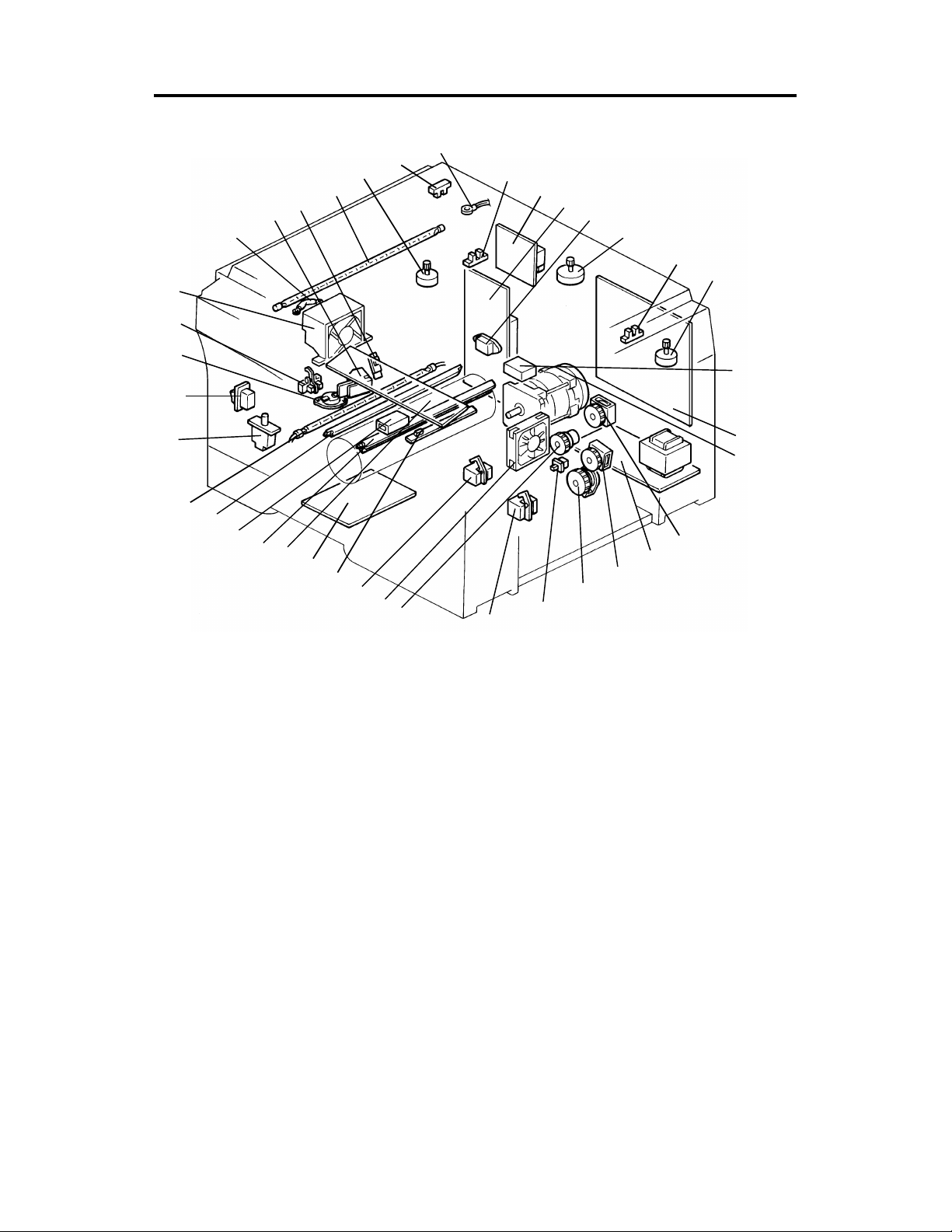
ELECTRICAL COMPONENT LAYOUT 24 June 1994
5. ELECTRICAL COMPONENT LAYOUT
17
16
15
13
14
12
11
18
10
19
9
24
23
22
21
20
25
26
27
28
29
30
31
32
33
34
8
7
6
5
4
3
2
1
37
38
35
36
1. Paper Tray Switch
2. Relay Sensor
3. Registration Clutch
4. Optics Cooling Fan Motor
(A152 only)
5. Registration Sensor
6. Image Density Sensor
7. Power Pack-TC/SC
8. Operation Panel Board
9. Erase Lamp
10. Total Counter
11. Quenching Lamp
12. Fusing Lamp
13. Front Cover Safety Switch
14. Main Switch
15. Fusing Thermoswitch
16. Exit Sensor
17. Exhaust Blower Motor
18. Optics Thermofuse
19. Auto Image Density Sensor
20. Fusing Thermistor
21. Exposure Lamp
22. Lens Motor
(A152 copier only)
23. Scanner Home Position
Sensor
24. Optics Thermistor
25. Lens Home Position
Sensor
(A152 copier only)
26. Power Pack-CC/Grid/Bias
27. AC Drive Board
28. Fusing Triac (115 V only)
29. Scanner Motor
30. 4th/5th Mirror Home
Position Sensor
(A152 copier only)
31. 4th/5th Mirror Motor
(A152 copier only)
32. Main Motor Capacitor
33. Main Board
34. Main Motor
35. Toner Supply Clutch
36. DC Power Supply Board
37. Relay Roller Clutch
38. Paper Feed Clutch
1-8
Page 12

24 June 1994 ELECTRICAL COMPONENT DESCRIPTIONS
6. ELECTRICAL COMPONENT DESCRIPTIONS
Motors
SYMBOL NAME FUNCTION
Drives all the main unit components except for the
M1 Main Motor
M2 Scanner Motor Drives the scanners (1st and 2nd). (dc stepper) 29
M3 Lens Motor
M4
M5
M6
4th/5th Mirror
Motor
Optics Cooling
Fan Motor
Exhaust Blower
Motor
optics unit and fans. (115/220–240 Vac [ac
synchronous])
Positions the lens according to the selected
magnification. (dc stepper)
… A152 copier only
Positions the 4th/5th mirrors according to the
selected magnification. (dc stepper)
… A152 copier only
Prevents built up of hot air in the optics cavity.
(24 Vdc)
… A152 copier only
Removes heat from around the fusing unit and
moves the ozone built up around the charge
section to the ozone filter. (24 Vdc)
INDEX
NO.
34
22
31
4
17
Magnetic Clutch
SYMBOL NAME FUNCTION
MC1
Registration
Clutch
Drives the registration rollers. 3
Magnetic Spring Clutches
SYMBOL NAME FUNCTION
MSC1
MSC2
MSC3
Toner Supply
Clutch
Relay Roller
Clutch
Paper Feed
Clutch
Drives the toner supply roller. 35
Drives the 1st and 2nd relay rollers. 37
Starts paper feed. 38
INDEX
NO.
INDEX
NO.
1-9
Page 13

ELECTRICAL COMPONENT DESCRIPTIONS 24 June 1994
Switches
SYMBOL NAME FUNCTION
SW1 Main Switch Supplies power to the copier. 14
SW2
SW3
Front Cover
Safety Switch
Paper Tray
Switch
Cuts the ac power line, when the front cover is
open.
Detects when the paper tray is set. 1
INDEX
NO.
13
Sensors
SYMBOL NAME FUNCTION
S1
S2
S3
S4
S5 Exit Sensor Detects misfeeds. 16
S6 Relay Sensor
S7
S8
Scanner Home
Position Sensor
Lens Home
Position Sensor
4th/5th Mirror
Home Position
Sensor
Registration
Sensor
Image Density
(ID) Sensor
Auto Image
Density Sensor
(ADS)
Informs the CPU when the 1st scanner is at the
home position.
Informs the CPU when the lens is at the home
position (full size position).
… A152 copier only
Informs the CPU when 4th/5th mirrors assembly is
at the home position (full size position).
… A152 copier only
1) Detects misfeeds.
2) Controls the relay roller clutch stop timing.
1) Detects when copy paper is set on the
by-pass feed table.
2) Detects misfeeds.
Detects the density of the image on the drum to
control the toner density.
Senses the background density of the original. 19
INDEX
NO.
23
25
30
5
2
6
Printed Circuit Boards
SYMBOL NAME FUNCTION
PCB1 Main Board
PCB2 AC Drive Board
PCB3
PCB4
DC Power
Supply Board
Operation Panel
Board
Controls all copier functions both directly and
through the other PCBs.
Drives the main motor, exposure lamp, fusing
lamp, and quenching lamp.
Converts the wall outlet ac power input to +5 volts,
+24 volts, and a zero cross signal.
Informs the CPU of the selected modes and
displays the copier status and condition on the
panel.
1-10
INDEX
NO.
33
27
36
8
Page 14
24 June 1994 ELECTRICAL COMPONENT DESCRIPTIONS
Lamps
SYMBOL NAME FUNCTION
L1 Exposure Lamp
L2 Fusing Lamp Provides heat to the hot roller. 12
L3 Quenching Lamp
L4 Erase Lamp
Applies high intensity light to the original for
exposure.
Neutralizes any charge remaining on the drum
surface after cleaning.
Discharge the drum outside of the image area.
Provides leading/trailing edge erase and side
erase.
INDEX
NO.
21
11
9
Power Packs
SYMBOL NAME FUNCTION
P1
P2
Power Pack
–CC/Grid/Bias
Power Pack
–TC/SC
Provides high voltage for the charge corona, grid,
and development roller.
Provides high voltage for the transfer and
separation corona.
INDEX
NO.
26
7
Counter
SYMBOL NAME FUNCTION
CO1 Total Counter Keeps track of the total number of copies made. 10
Others
SYMBOL NAME FUNCTION
TH1
TH2
TS
TF
C
TR Fusing Triac
Fusing
Thermistor
Optics
Thermistor
Fusing
Thermoswitch
Optics
Thermofuse
Main Motor
Capacitor
Monitors the fusing temperature. 20
Monitors the optics temperature. 24
Provides back-up overheat protection in the fusing
unit.
Provides back-up overheat protection around the
exposure lamp.
Start capacitor. 32
Switches the fusing lamp on and off. (115 V only)
Note: In the 220V-230V/240V version, the triac
is built-in the ac drive board
INDEX
NO.
INDEX
NO.
15
18
28
1-11
Page 15
G2: Relay Gear
G8: Relay Gear
BP4
DRIVE LAYOUT 24 June 1994
7. DRIVE LAYOUT
G14
G13
G15
G16
G17
G18
G19
G1: Main Motor Gear
BP6 BP5
G22 BP1G21G20
G26
G25
TB2
TB3
TB1
BP2
G12 G11
G10
G23
G2G1
G9
G8
G7
G6
G5
G4
G3
BP3
G24
G9
G8
G2
G1
G23: Timing Belt Drive
Gear
BP1: Timing Belt Pulley
TB1: Timing Belt
A
G10 Relay gear
G11: Timing Belt Drive Gear
BP5: Timing Belt Pulley
TB3: Timing Belt
Development Section
BP6: Timing Belt Pulley
G12: Development Gear
Development Unit
G13: Relay Gear
G14: Toner Supply CL Gear
Toner Supply CL
Toner Supply Unit
G9: Relay Gear
B
Cleaning Unit
G3: Fusing Drive Gear
Fusing and Exit Unit
G4: Hot Roller Gear
G7: Relay Gear
G6: Relay Gear
G5: Exit Roller Gear
1-12
Page 16
B
24 June 1994 DRIVE LAYOUT
A
G15: Registration CL
Gear
Registration CL
Registration Rollers
G20: Relay Gear
G17: Relay Roller CL
Gear
Relay Roller CL
G16: 2nd Relay Roller
Gear
2nd Relay Rollers
Paper Feed Section
BP2: Timing Belt Pulley
G22: Relay Gear
Paper Feed Section
G21: Paper Feed CL
Gear
Paper Feed CL
Feed Rollers
G24: Timing Belt Drive
Gear
BP3: Timing Belt Pulley
TB2: Timing Belt
BP4: Timing Belt Pulley
G25: Relay Gear
G26: Drum Drive Gear
G18: Relay Gear
G19: 1st Relay Roller
Gear
1st Relay Rollers
1-13
Page 17
POWER DISTRIBUTION 24 June 1994
8. POWER DISTRIBUTION
AC Power (115V or 220V – 240V)
Fusing Lamp
Exposure Lamp
Main Motor
Quenching Lamp
Document Feeder
(Option)
AC power
DC power
Main SW
Cover Safety SW
Power Relay
(RA401)
Fusing Lamp
Drive Circuit
Exposure Lamp
Drive Circuit
Main Motor
Relay (RA402)
AC Drive Board
DC Power
Supply Board
24V (VA)
24V (VA)
24V (VA)
24V (VA)
24V (VA)
5V (VC)
Zero Cross
RAM
Pack
Main
Board
Anti-condensation Heaters
-Drum (Option)
-Optics (Option)
5V
Scan
Signal
5V (VC)
24V (VA)
5V (VC)
24V (VA)
Operation Panel Board
Sensors
Switches
DF Interface Board
(A152 copier only)
Thermistors
Solenoids
Clutches
Power Packs
Lens Motor
(A152 copier only)
4th/5th Mirror Motor
(A152 copier only)
Optics Cooling Fan
Motor (A152 copier only)
Exhaust Blower
Motor
Image Density Sensor
Scanner Motor
When this copier is plugged in and the main switch is turned off, ac power is
supplied via the ac drive board to the optio na l ant i-con de nsa tio n heat ers.
When the front cover and/or the exit cove r is open , th e cove r sa fe ty switch
completely cuts off power to all ac and dc compo nent s. The RAM pack has a
back up power supply (dc battery) for th e service prog ram mode data and
misfeed job recovery.
When the main switch is turned on, the ac power sup ply to the
anti-condensation heat er is cut of f an d ac power is supp lied to the ac drive
board. The dc power supply board receive s wa ll out let ac powe r through the
ac drive board.
The dc power supply board converts th e wall outle t ac po wer inp ut to +5
volts, +24 volts, and a zero cross signa l, all of wh ich are supp lied to th e main
board.
1-14
Page 18

24 June 1994 POWER DISTRIBUTION
The main board supplies dc powe r to all cop ier dc comp on ents. All sensors,
switches, thermistors, and the DF interf ace board (op tio n) op era te on +5
volts. The operatio n pane l o per at es on +5 vo lts sup plied by the main board.
All other dc components includin g the power relay (RA401) and the main
motor relay (RA402) operat e on +24 volt s.
When the main board receives power, it act ivat es th e power rela y (RA401)
which then supplies ac power to the fusin g lamp drive circuit, and the
exposure lamp drive circuit on the ac drive board. The fusing lamp drive
circuit receives a trigger signal from th e main boa rd and the fusing lamp
lights. The exposure lamp do es no t tu rn on unt il t he ma in bo ard send s a
trigger pulse to the exposure lamp drive circu it.
When the Start key is pressed, the main bo ard ene rgize s the main mot o r
relay (RA402). Then, the ma in mot or an d the quenching lamp turn on.
When the main switch is turned off, power is cut off to the main board an d to
RA401, and the optional drum and optics anti-condensation heaters are
turned on.
1-15
Page 19

SECTION 2
DETAILED SECTION
DESCRIPTIONS
Page 20

24 June 1994 DRUM
1. DRUM
1.1 DRUM CHARACTERISTICS
An organic photoconductor (OPC) dru m is used in this mo del.
The OPC drum has the characteristics of :
1. Being able to accept a high negative electrical charge in the dark. (Th e
electrical resistance of a photocon ductor is high in the absence of light.)
2. Dissipating the electrical charge when exposed to light. (Exposure to light
greatly increases the conduct ivity of a photo con du cto r.)
3. Dissipating an amount of charge in dire ct pro po rtio n to the inte nsity of the
light. That is, where strong er ligh t is directed to the photoconductor
surface, a smaller voltage remains on the drum.
4. Being less sensitive to changes in tempe rature (when compared to
selenium F type drums).
5. During the drum’s life, drum residu al voltage gradually increases and the
photoconductive surface becomes worn.
Therefore, some compen sat ion for these characteristics is required.
2-1
Page 21
DRUM 24 June 1994
1.2 DRUM UNIT
[E]
[A]
[G]
[F]
[C]
[D]
[B]
[C]
[D]
The drum unit [A] consists of an OPC drum [B], ID sensor board [C] and a
pick-off pawl [D]. When the drum, the pick-off pawl, or th e ID sensor is
replaced or cleaned, the drum unit must be removed from the copier.
Therefore, the drum has a coupling device wh ich is connected to the drum
drive gear [E]. The ID sensor conne cto r [ F] is used for th e ID sen sor.
The main motor provides rotat ion direct ly to th e drum thro ug h a series of
gears.
The pick-off pawl [D] is always in cont act with the drum surface.
2-2
Page 22
24 June 1994 DRUM CHARGE
2. DRUM CHARGE
2.1 OVERVIEW
[A]
[B]
[D]
[A]
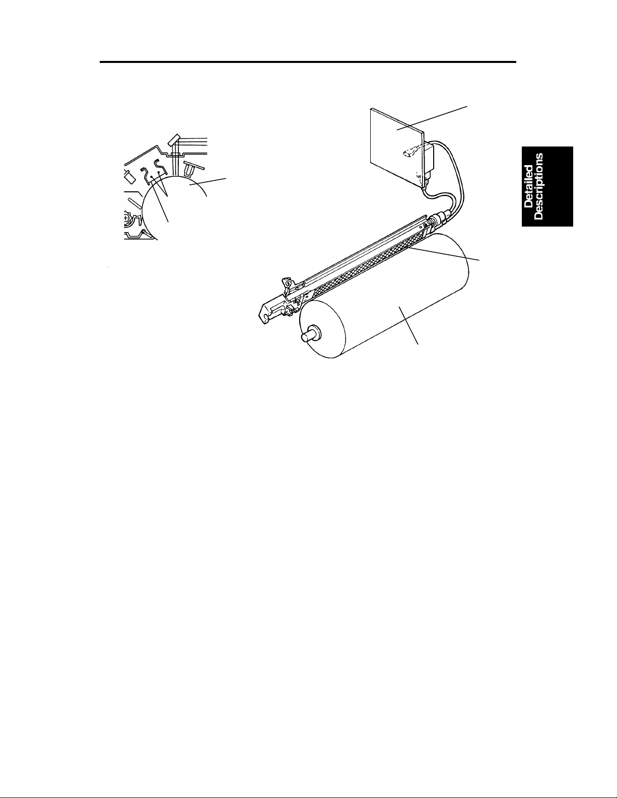
This copier uses a double wire scorotro n and a highly sensitive OPC drum
[A]. The corona wires [B] ge ne rat e a corona of negative ions when the
CC/Grid/Bias power pack [C] applies a high voltage. The CC/Grid/Bias power
pack also applies a negative high volta ge to a stainless steel grid plate [D].
This insures that the drum coating receives a uniform negative charg e as it
rotates past the corona unit.
[C]
[D]
The exhaust fan, located abo ve the cop y exit, causes a flow of air from the
upper area of the development unit through the ch arg e coro na unit . This
prevents an uneven bu ild-u p of negative ions that can cause uneven image
density. The exhaust fan runs at half spe ed when in the st and-by condition
and at full speed while copying.
The exhaust fan has an ozo ne filte r (a ctive ca rbo n) which adsorbs ozone (O3)
generated by the cha rge corona. The ozone filte r decre ases in efficiency over
time as it adsorbs ozone. The ozone filter should be replaced at every 80K
copies.
The flow of air around the charge corona wires may deposit paper dust or
toner particles on the corona wire . The se pa rticle s may interfere with
charging and cause low density ba nds on cop ies. The wire cleaner cleans
the corona wire when the op era tor slides the corona unit out and in.
2-3
Page 23
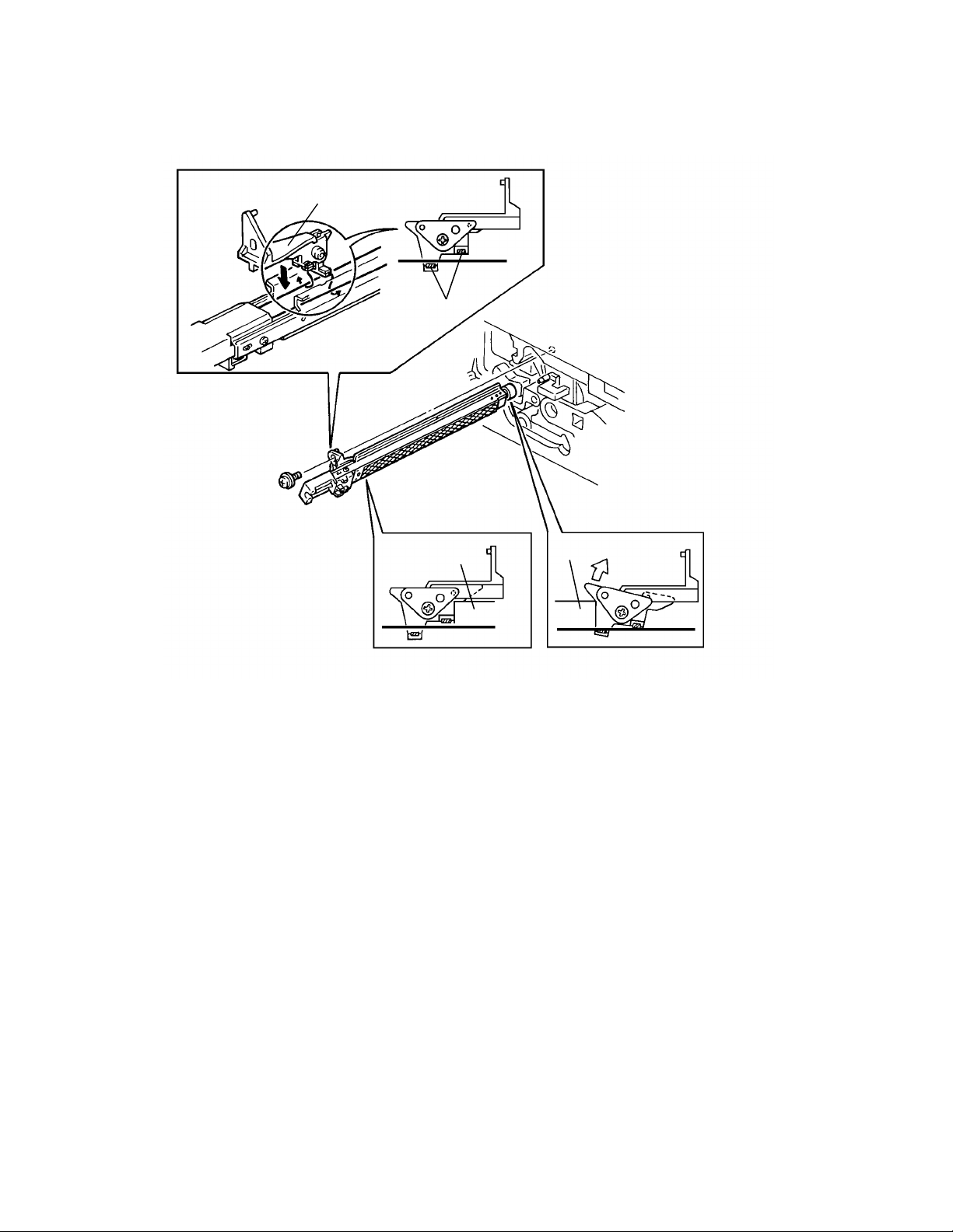
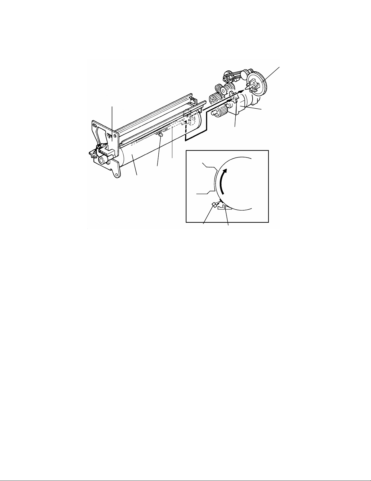
DRUM CHARGE 24 June 1994
2.2 CHARGE CORONA WIRE CLEANER MECHANISM
[B]
[A]
[D]
[C]
Pads [A] above and below th e charge corona wires clean the wires as th e
charge unit is manually slid in and out.
The cleaner pad bracket [B ] rotates when the charge unit is fully e xte nd ed
and the bracket is pulled up against the rear en dblock [C]. This moves the
pads against the corona wires (see illu stra tio n). If the charge unit is not fully
extended, the pads do not tou ch th e corona wires.
The pads move away from the wires when the charg e unit is fu lly inse rte d
and the cleaning bracket is pushed against the front endblock [D].
After copier installa tio n the key operator should be instru cte d to use this
mechanism when copies have whit e stre aks.
2-4
Page 24
Power Pack CC/Grid/Bias
(P1)
Charge Corona
Development
Bias
24 June 1994 DRUM CHARGE
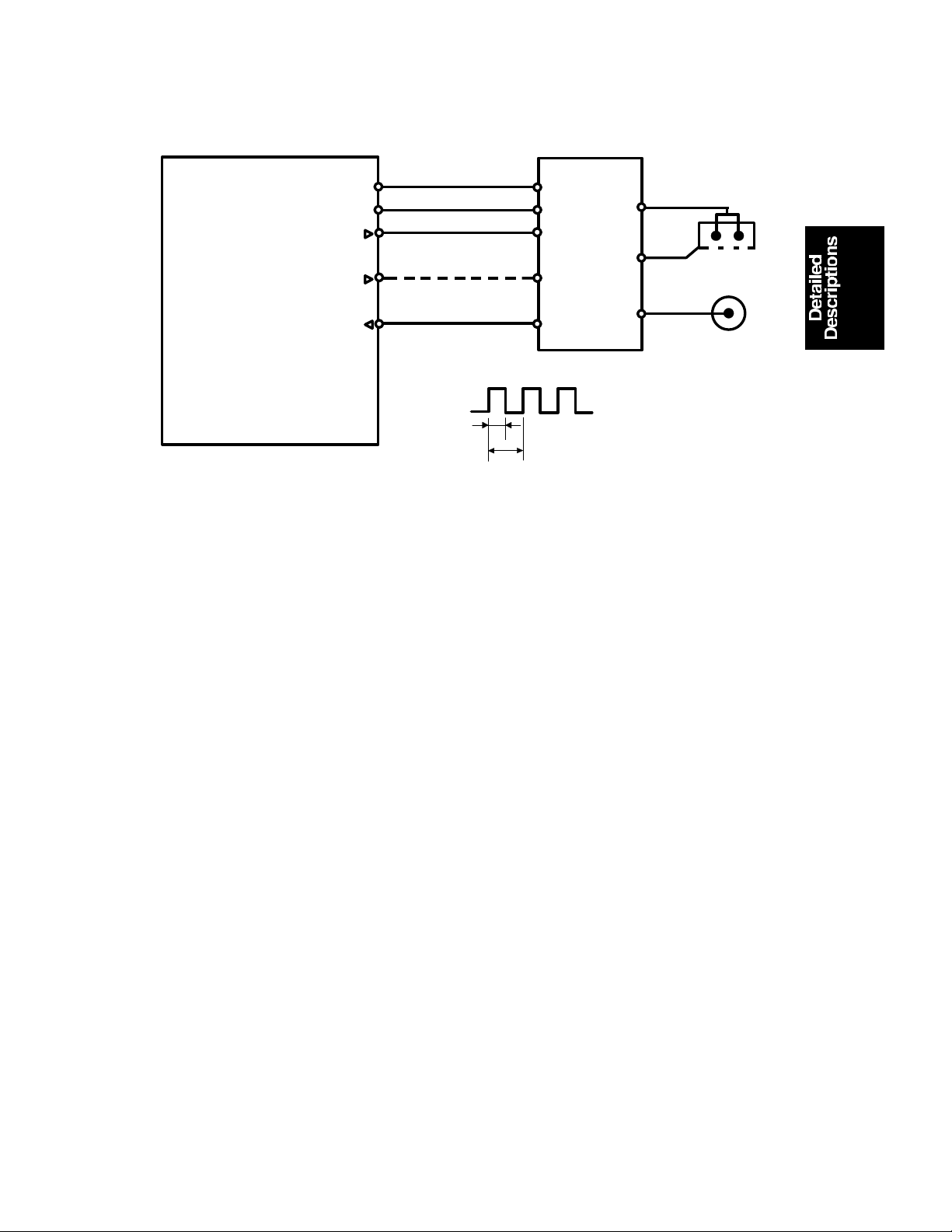
2.3 CHARGE CORONA CIRCUIT
t2
CN1-1
CN1-2
CN1-3
CN1-5
CN1-7
t1
C
G
B
PWM Duty cycle
=t2/t1 x 100 (%)
Grid
CC Trig [
Grid Trig (PWM) [
Main Board (PCB 1)
▲0→0/5]
GND [0]
VA [24]
VC [5]
▼24]
CN119-7
CN119-6
CN119-5
CN119-3
CN119-1
The main board supplies +24 volt s to th e CC/G rid/Bias power pack at CN1-1
as the power supply source. Afte r t he Sta rt key is pressed the CPU drops
CN1-3 from +24 volts to 0 volts. This energizes the charge coron a circuit
within the CC/Grid/Bias power pack, which applies a high nega tive volta ge of
approximately –7.0 K volts to th e cha rge corona wires. The corona wires then
generate a negative corona charge.
The grid plate limits the cha rge voltage to ensure that the charge does not
fluctuate and that an even charge is applied to the drum surfa ce.
The grid trigger pulse applied to CN1-5 is a pulse width modulated signal
(PWM signal). This signal is not only a trigger signal, it also chan ges the
voltage level of the grid. As the width of the pulse ap plie d incre ases, the
voltage of the grid also incre ases.
2-5
Page 25

DRUM CHARGE 24 June 1994
2.4 GRID VOLTAGE CORRECTI ON
To maintain good copy quality ove r the drum’s life , th e grid volta ge is
changed by the following:
• Drum residual voltage correction (Vr correction)
• Drum wear correction
2.4.1 Drum Residual Voltage Correction (Vr correction)
During the drum’s life, the dru m may fat igue electrically and residual voltag e
(Vr) on the drum may gradually in crea se. Wh en this ha ppen s, th e corona
charged voltage on th e dru m is not discharged enough in the quenching and
exposure processes. Even if the development bias is applied in the
development pro cess, the backg round area of the original on th e drum may
attract some toner. This may cause dirty background on copies. The Vr
correction prevents this ph enomenon as follows:
A pattern (Vr pattern) is develope d on the drum eve ry 1,0 00 copie s and its
reflectivity is detected by the ID sensor to measu re th e residua l volta ge . This
is called residual voltage detect ion . (If the reflectivity is low, the residual
voltage will be high.) When the Vr pattern is developed, all blocks of the
erase lamp turn on, and th e de velo pment bias voltage is 0 volt.
The CPU determines what level of Vr co rrect ion is necessa ry dep en din g on
the output (Vr ratio [L]) from the ID sensor.
Vrp
L =
x 100 (%)
Vsg
Vrp: ID sensor outp ut for Vr pattern
Vsg: ID sensor output for bare drum
The current Vr ratio is disp laye d by SP67.
The CPU increases the development bias voltage depending on the Vr ratio
to prevent dirty backgrou nd on copies, (See page 2-30 for more informatio n. )
The CPU also increases the grid volta ge to ensure prop er imag e de nsit y
depending on the Vr ratio. (See page 2-8.)
2-6
Page 26

24 June 1994 DRUM CHARGE
2.4.2 Drum Wear Correction
During the drum’s life, the photoco nd uct ive surf ace of the drum becomes
worn by contact with the cle an ing blad e an d de veloper on the development
roller. This effects ability of th e dru m t o hold a cha rge . This cha racteristic
especially affects develo ping of the ID sensor patte rn. Th e ID sen sor pa ttern
developed on the dru m becomes lighter causing highe r ton er concentration in
the developer. The drum we ar corre ctio n is made to pre ven t th is
phenomenon and is as follows:
The CPU keeps track of the drum motor rota tion time that corresponds to the
wear of the photoconductive layer. The grid voltage for the toner density
detection increases at set int erval. The grid voltage for the residual voltage
(Vr) detection also increase s at th e same interval. (See page 2-9.) The drum
motor rotation time is displayed by SP57.
2.5 GRID VOLTAGE FOR IMAGE DENSITY CONTROL
The main board controls the grid volt age fo r the copy imag e through the
CC/Grid/Bias power pack. As the grid voltage for the imag e densit y control
becomes less, the copy image become s light er an d vice versa .
The grid voltage is based on the standard grid voltage and correction factors
as follows:
Grid Voltage = Standard image density grid volt age (–6 80 volts [SP60 = 4])
+
Vr correction factor
+
Auto image density level facto r (S P34)
2.5.1 Standard Image Density Grid Voltage
The standard image density grid voltage (SP60) is set at the factory and the
setting is differen t for each machine. The setting of SP60 is described on the
SP mode data sheet located inside the inner cover of the machine.
2-7
Page 27

DRUM CHARGE 24 June 1994
2.5.2 Drum Residual Voltage (Vr) Correction Factor
Vr ratio (L) (%) (SP67) Change of grid voltage (volts)
100 to 84
83 to 58 –40
57 to 41 –80
40 to 28 –120
27 to 0 –160
±0
L = Vrp/Vsg x 100 (%)
Vrp: ID sensor output for Vr pattern
Vsg: ID sensor output for bare drum
During the drum’s life, drum residual volt age (Vr) may gradually increase. Vr
correction compensate s fo r the resid ua l voltage on the drum. The Vr
correction is done every 1000 copies. The CP U increa ses the development
bias voltage and the grid volta ge . The above table shows how the grid
voltage changes depending on the Vr ratio.
2.5.3 Auto Image Density Level Factor (SP34)
Auto image density level Data (SP34) Change of grid voltage (volts)
Normal 0 *
Darker 1 –40
Lighter 2
±0
±0
* Factory setting
The grid voltage and the expo sure la mp volt ag e are co nst an t reg ardless of
the output from the auto image de nsit y sensor. Only the development bia s
voltage varies depending on the output from the auto image density sen sor.
But only when the auto image density level data in SP34 is set to darker, the
grid voltage is changed –40 volts as shown in the above ta ble . Whe n it is set
to lighter, the grid vo lta ge doe s not chan ge . Howe ver, the development bias
voltage is corrected.
2-8
Page 28
24 June 1994 DRUM CHARGE
2.6 GRID VOLTAGE FOR TONER DE NSITY DETECTION AND
RESIDUAL VOLTAGE (Vr) DETECTION
The guid voltage is the same fo r both toner density detectio n an d resid ua l
voltage correction.
Grid voltage = Standard ID sensor grid voltage (–460 volt s [SP 62 =4] )
+
Drum wear correction factor (SP57)
Drum Wear Correction Factor (SP57)
Main motor rotation time (SP57) Change of grid voltage (volts)
0 to 2H
2 to 65H –20
65 to 112H –40
112 to 157H –60
More than 157H –80
±0
The grid voltage for toner density detection is the same as it is for th e
residual voltage (Vr) detection. However, the developme nt bias volt ag e is
different. (See page 2-30 and 2-35.)
2-9
Page 29
[E]
OPTICS 24 June 1994
3. OPTICS
3.1 OVERVIEW
[B]
[C]
[D]
During the copy cycle, an image of the original is reflecte d onto the drum
surface through the optics assembly as follows.
Light Path:
Exposure Lamp [A] → Original → First Mirror [B] → Second Mirror [C]
→ Third Mirror [D] → Lens [E] → Fourth Mirror [F]→ Fifth Mirror [G]
→ Sixth Mirror [H] → Drum [I]
[A]
[H] [F] [J]
[I]
[G]
This copier has six standard reprod uct ion ratios (A152 copier only), three
reduction ratios, two enlarg eme nt ra tio s, an d full size. It also has a zoom
function. The opera tor can change the reprod uct ion ratio in one percent steps
from 61% to 141%.
Stepper motors are used to cha nge th e positio ns of the lens and mirrors
(A152 copier only). Separate mot ors are used beca use the wide ran ge of
reproduction ratios make s it mechanically difficult for one motor to posit ion
both the lens and mirrors. A ste pp er motor is also used to drive the scanner.
This motor changes the scanner spe ed accord ing to th e rep rod uction ratio.
2-10
Page 30

24 June 1994 OPTICS
The CPU monitors the temperature aro un d the optics cavit y thro ugh a
thermistor which is located at the up per le ft rear side of the copier frame.
When the temperature reaches 45°C, the optics cooling fan [J] (A15 2 cop ier
only) starts rotating to draw cool air into the optics cavit y. However, A151
copier is not equipped with a cooling fan. The machine will stop if the optics
cavity overheats. (Se e pa ge 6-52.) In this case, the Energy S ave r in dica tor
blinks and the Start key turns red.
The air flows from the right to the left , and exh au sts th rou gh the vent s in the
left side of the upper cover. This fan operates until t he te mp erature drops
below 45°C.
The thermofuse pro vides back-up overheat prot ect ion. It opens at 128°C and
removes ac power to the exp osure lamp.
2-11
Page 31

[B]
[F]
[C]
OPTICS 24 June 1994
3.2 SCANNER DRIVE
[D]
[E]
[A]
[G]
3.2.1 1st and 2nd Scanner Drive Mechanism
This model uses a stepper mot or [A ] to drive the scanners. Both ends of ea ch
scanner are driven to prevent skewin g. The scanners have sliders [B], wh ich
ride on guide rails.
The scanner home position is detected by the home positio n sensor [C]. The
scanner return position is determine d by cou nt ing the scann er mot or drive
pulses.
The first scanner [D], which consists of the exposu re lamp and the first mirror,
is connected to the scanner drive wire by the wire clamps [E]. The second
scanner [F], which consists of th e seco nd and third mirro rs, is conn ect ed to
the scanner drive wire by movable pulleys (the second scann er pulleys [G ]).
The pulleys move the second scanne r at half the velocity of the first scanner.
This maintains the focal distance between the original and the lens during
scanning. This relationship can be expressed as:
V1r = 2 (V2r) = VD/r
where r = Reproduction rat io
V1r = First scanner velocity (when the reproduction ra tio
is "r")
V2r = Second scanner velocity (when the reprod uct ion ra tio
is "r")
VD = Drum peripheral velocity (100 mm/s)
2-12
Page 32

: Reduction
: Enlargement
24 June 1994 OPTICS
3.3 LENS DRIVE (A152 copier only)
[C]
[D]
[B]
[A]
3.3.1 Lens Drive
The lens motor [A] (stepper motor) changes the lens [B] position through the
lens drive wire [C] in accordance with the selected reprod uction ratio to
provide the proper optical distan ce between the lens and the drum surface.
The rotation of the lens drive pulley moves the lens back and fort h in discre te
steps. The home position of the len s is dete cte d by th e home position sensor
[D]. The main board keeps track of the lens position base d on the numb er of
pulses sent to the lens mo to r.
2-13
Page 33

[B]
OPTICS 24 June 1994
3.3.2 Lens Positioning
[C]
[A]
Home Position (100%)
(100% → 141/129%)
[D]
Reduction SideEnlargement Side
(141/129% → 71/65%)
(71/65% → 93%)
(93% → 71/65%)
(71/65% → 141/129%)
(141/129% → 122/121%)
(122/121% → 141/129%)
(122/121% → 100%)
(100% → 71/65%)
(71/65% → 100%)
The lens home position sensor [A] informs the main board when the lens is at
full size position (home position). The main board dete rmine s the lens sto p
position in reduction an d en largement modes by countin g th e nu mbe r of
steps the motor makes with reference to the lens home position. When a new
reproduction ratio is select ed , th e lens [B] moves directly to the selected
magnification position.
The lens home position is registe red each time the lens starts from or passes
through the lens ho me posit ion sensor. As the lens moves from t he
enlargement side to the reduction side, the senso r re gist ers the home
position. This occurs when the actu at or plate [C] enters the lens home
position sensor.
A small vibration can be observed when the lens moves through home
position from the red uct ion side to the enlargement side because the lens is
going in the wrong direction to register the home positio n. The len s
overshoots the home position by on ly one pulse before going back to register
the home position.
The lens always stops while moving from lef t to rig ht (as viewed from the
front) to minimize the erro r cause d by mechanical play in the drive gears [D].
2-14
Page 34

(71/65% → 100%)
24 June 1994 OPTICS
3.4 4TH/5TH MIRROR DRIVE (A152 copier only)
[B]
[A]
Home Position (100%)
(100% → 141/129%)
(141/129% → 71/65%)
(71/65% → 93%)
(93% → 71/65%)
(71/65% → 141/129%)
(141/129% → 122/121%)
(122/121% → 141/129%)
(122/121% → 100%)
(100% → 71/65%)
3.4.1 Drive
The 4th/5th mirror drive motor (stepper motor) changes the 4th/5th mirror
assembly position throug h th e pin ion gears [A] and the rack gear [B] in
accordance with the selected reproduction ratio to provide the proper optical
distance between the lens and drum surf ace .
3.4.2 Positioning
The positioning mechanism is similar to that of lens po sitio ning, as shown in
the above positioning chart. The 4th/5th mirror assembly always st ops while
moving from right to left (a s viewed from th e front).
2-15
Page 35

OPTICS 24 June 1994
3.5 AUTOMATIC IMAGE DENSITY SENSING
[C]
[B]
[A]
Sampled area
70 mm
a
b
Light from the exposure lamp is reflected from the original and travels to the
lens [A] via the mirrors. The auto ID senso r [B] , a phot odiode, is mounted on
the upper front frame. The sensor cover [C] has a hole in it to allow light to
fall directly onto the sensor. Sampling starts 10 millimete rs from th e leadin g
edge of the original and continues for 50 millimeters from the leadin g edge of
original in full size mode. The length of "a" and "b" will vary depending on the
selected reproduction rat io (A152 copier only).
The lengths "a" and "b" in each reproduction ratio are calcu lated as follows:
a =
Reproduction Ratio (%)
10 mm
x 100 b =
Reproduction Ratio (%)
50 mm
x 100
The photosensor circuit converts the light intensity to a voltage. The dete cte d
voltage is amplified and sent to the main PCB. The CPU stores the voltage of
each sampled point in RA M. It the n comp utes the image density of the
original from the maximum sample volt ag e and changes the development
bias accordingly. (See page 2-2 8 for d et ails. ) The exposure lamp voltage is
constant regardless of the image density of the origin al.
2-16
Page 36

24 June 1994 OPTICS
3.6 EXPOSURE LAMP VOLTAGE CONTROL
The main board controls the expo sure lamp voltage through the ac drive
board. The exposure lamp voltage is based on the base lamp vo lta ge and
various correction factors. The method of control is different dep ending on
whether the image density is manually selected or the auto image density
mode is selected.
The exposure lamp voltage consist s of th e followin g fa cto rs:
Exposure lamp voltage = Base exposure lamp voltage
(Manual or auto image density mode)
+
VL correction factor
+
Reproduction ratio correction factor
(A152 copier only)
3.6.1 Base Lamp Voltage In Manual Image Density Mode
Manual ID Level
Exposure Lamp Data
Darker Lighter
123456 7
Vo –4 Vo –4 Vo –2
Vo ±0
Vo+2 Vo+2 Vo+4
The above table shows chan ge s in the expo sure lamp data in the manual
image density mode.
SP48 sets the exposure lamp data for level 4 (Vo) of manual image density
mode. A value from 100 to 15 0 can be sele cte d.
3.6.2 Base Lamp Voltage In Auto Image Density Mode
In the auto ID mode, the CPU selects the level 4 (Vo) exposu re lamp data
(SP48) regardless of the inpu t fro m the auto imag e de nsit y senso r.
2-17
Page 37

OPTICS 24 June 1994
3.6.3 VL Correction Factor
The light intensity may decrea se be cause of dust accumulated on th e op tics
parts. This may cause dirty backgrou nd on copies. To compensate for this
phenomenon, VL correction is done as follows:
Whenever SP56 (ADS reference volt age adjust men t) is p erf orme d, before
sampling starts for the ADS adjustment, the auto ID sensor measure s the
amount of light reflected through the 1st , 2nd and 3rd mirrors from th e white
plate located under the left frame. The photosensor circuit converts th is lig ht
intensity to a voltage and the CPU stores it in memory as the initial dat a.
The machine has a softwa re cou nter for the VL correction. At every 500
copies the machine measures the light intensity reflected from the white
plate, and this is compared wit h th e init ial da ta stored in memory.
If the measured volt ag e dif ference is/or more than 0.1 volts, +1 will be added
to the exposure lamp dat a as the VL correction factor.
If the difference is less than 0.1 volts, no correction will be applied .
The total increase fo r VL correction cannot exceed +2 0. Aft er cleaning the
optics parts, the following act ion s must be perf orme d in ord er.
• SP95: Clear the exposure lamp data and the softwa re cou nter
by entering "1".
• SP48: Perform the light intensity adjust men t.
• SP56: Perform the ADS adjustment (to sto re the new initial
data and to adjust the ADS reference voltage.)
3.6.4 Reproduction Ratio Correction Factor (A152 copier only)
Reproduction ratio (%) Change of exposure lamp data
61 and 62 +2
63 to 119
120 to 129 +2
130 to 141 +4
±0
The exposure lamp data is in crea sed depending on the selected
magnification ratio in ord er to compensate for the change in the concen tra tio n
of light on the drum.
2-18
Page 38

24 June 1994 OPTICS
3.7 EXPOSURE LAMP CONTROL CI RCUIT
Main Board (PCB1)
Zero
Cross
CN107-1
AC Drive Board (PCB2)
B
CPU
TP111
(EXPO)
E
Feed back
signal
0V
+24V
C
24V
0V
Trigger Pulse
AC power
Zero cross
Trigger pulse
CN114-2
CN114-1
CN114-7
CN114-3
CN401-7
CN401-8
CN401-2
CN401-6
VR401
R403
R401
A
B
C
PC401
R404
R405
C401
ZD
401ZD402
ZD
403ZD404
R411
TRC401
D401
R406
R413
D404
~D407
CR401
L401
L402
CN421
240V
220V
220V Only
TR401
C411
T402
CN419-1
Thermofuse (TF)
Exposure
Lamp
D
CN419-2
T407
(L1)
A
AC115V
AC220V
AC240V
Lamp power
Feedback
signal
D
E
Feedback
The main board sends lamp trigg er (LO W sig nal) p ulse s to th e ac drive boa rd
from CN114-3. PC401 activates TRC401, which provides ac power to the
exposure lamp, at the lead edge of each trigger pulse.
The voltage applied to the expo sure lamp is also provided to the fee dback
circuit. The feedback circuit steps down (TR401), rectif ies (D404 ∼ 407), and
smoothes (zener diodes and capacitors) the lamp voltage. The CPU monit ors
the lowest point of the smoot he d wave (f eedb ack sign al), which is directly
proportional to the actu al lamp voltage.
The CPU changes the timing of the trigger pulses in response to the
feedback voltage. If the lamp voltage is too low, the CPU sends the trigg er
pulses earlier so that more ac power is applie d to the expo sure lamp. This
feedback control is performed instantly; so, the lamp voltage is always stable
even under fluctuating ac power conditions.
The voltage applied to the expo sure lamp can be changed with SP48 (Light
Intensity Adjustment). The ADS volta ge adju stme nt (SP5 6) must be done
whenever the light intensity adjustment is done.
2-19
Page 39

[A]
LE
EL
ERASE 24 June 1994
4. ERASE
4.1 OVERVIEW
[B]
SE
ES
LO
LC
LE: Lead edge erase margin 2.5 ± 1.5 mm
SE: Side erase margin 2.0 ±2.0 mm on each side ;
total of both sides 4 mm or less
LO: Original width
LC: Charged width of drum
EL: Lead edge erase
ES: Side erase (A152 copier only)
The erase lamp [A] consists of a sing le row of LEDs (29 LEDs) ext en din g
across the full width of th e dru m [B] .
The erase lamp has the fo llowin g functions: lead edge erase , side erase
(A152 copier only), and trail edge erase.
2-20
Page 40

24 June 1994 ERASE
abcde
h
g
fc
abde
4.1.1 Lead Edge Erase
The entire line of LEDs turn on when the main mot or tu rns on . The y stay on
until the erase margin slight ly overla ps the lead edge of the original image
area on the drum (Lead Ed ge Erase Ma rgin ). This prevents the toner density
sensor pattern fro m being developed every copy cycle and th e sha do w of the
original edge from being deve loped on the paper. At this point , side erase
starts (A152 copier only). The width of the lead edge erase ma rgin can be
adjusted using SP 41 .
During the toner density detection cycle (once every ten copy cycles), a block
of erase lamps (labeled "g" above) turns off long enough for th e sen sor
pattern to be developed.
The entire line of LEDs turn on when the re sidu al volt ag e on the OPC dru m is
being detected (Vr detectio n).
4.1.2 Side Erase
Based on the combinat ion of copy paper size and the reprod uct ion ratio data,
the LEDs turn on in blocks (labeled "a" – "g" above ). This reduces toner
consumption and drum cleaning load.
2-21
Page 41

ERASE 24 June 1994
– A152 copier–
This machine has no sensors or switches to detect the copy paper size.
Instead, the CPU measures the copy paper lengt h usin g the registration
sensor during the first copy cycle. Base d on this len gt h data , th e CPU
determines which copy paper size is used in the paper tray. (See page 2-49
for more information.)
The LEDs turn on in blocks as labe led "a" – "h" on the previous page.
In the full size copy mode, the CPU determines which blocks turn on base d
on the copy paper len gt h da ta as follows:
Paper length Paper size Blocks ON
364 mm and 356 mm B4, 10" x 14", 8
1/2" x 13", 81/4" x 13" (F4), 8" x 13", 81/2" x
330 mm and 279 mm
297 mm, 267 mm, and 254 mm A4R, 8" x 10
257 mm, 216 mm, and 210 mm B5R, 5
For toner density detection cycles. a – f, h
For residual voltage (Vr) detection cycles. All
8
11"
1/2" x 81/2", A5R a – e
1/2" x 14", 81/4" x 14" None
a – b
1/2", 8" x 10" a – c
NOTE: Since the CPU cannot distinguish different paper widt hs, the CPU
determines the size to be the larger standard width based on the
measured length.
(EX: 10" x 14", 81/2" x 14" → The CPU recognizes as 10" x 14".)
In the reduction or enlarge ment copy mode, the CPU determines which
blocks turn on based on the selected repro du ctio n rat io as fo llows:
Reproduction ratio (%) Blocks ON
83 to 99, 101 to 141 None
78 to 82 a
73 to 77 a to b
68 to 72 a to c
64 to 67 a to d
61 to 63 a to e
2-22
Page 42

24 June 1994 ERASE
– A151 copier –
Since this model has only two modes for the erase lamp, full erase mode (all
blocks on) and toner density detection cycle mode (all blocks on except block
"g"), side erasing is not performe d by th e era se lamp.
When making copies with th e platen cover open condition, and the original
and the copy paper is smaller than B4 (10" x 14"), the part without the original
will be developed as black image area on the drum.
NOTE: If the customers makes copies without the platen cover closed
frequently, the used toner ta nk may be come full in a fa ster period
than expected. For t ho se cust omers, the toner tank must be checked
and cleaned frequently.
4.1.3 Trailing Edge Erase
The entire line of LEDs turns on after the trailing edge of the latent image has
passed. Therefore, a trailing erase margin cannot be obse rved on the copy.
The LEDs stay on to erase th e leading edge of the lat en t imag e in the next
copy cycle. After the fin al copy, the erase lamps turn off at th e same time as
the main motor.
2-23
Page 43

[D]
DEVELOPMENT 24 June 1994
5. DEVELOPMENT
5.1 OVERVIEW
[E]
[B]
[C]
[A]
When the main motor turns on, th e pa ddle roller [A], development roller [B],
auger [C], and the agitator [D] start turnin g. The paddle rolle r picks up
developer in its paddles and transports it to the development roller. Internal
permanent magnets in the development roller attract the developer to the
development roller sleeve .
The turning sleeve of the deve lop ment roller then carries the developer past
the doctor blade [E]. The doct or blade trims the developer to the desired
thickness and creates deve lop er ba ckspill to the cross-mixing me cha nism.
The development roller con tin ue s to tu rn, carrying the deve lop er to the OPC
drum. When the developer bru sh con ta cts th e dru m surface, the negatively
charged areas of the drum surfa ce at tra ct an d hold th e positive ly ch arg ed
toner. In this way, th e lat en t imag e is d eve loped.
The development roller is given a negat ive bia s to pre ven t toner from being
attracted to the non-image areas on the drum which may have a residua l
negative charge. The bias also cont rols image density.
After turning abou t 10 0 de gre es more, the development roller releases the
developer to the deve lopment unit. The develope r is agita ted by the paddle
roller [A], agitator [D], and the cross- mixing mecha nism.
2-24
Page 44

24 June 1994 DEVELOPMENT
5.2 DRIVE MECHANISM
[F]
[C]
[G]
[B]
[E]
[D]
[A]
When the main motor [A] turns, the rota tio n is tran smitted from the
development drive gear [B] to th e de velopment roller gear [C] throug h the
development gear [D] , timin g belt [E ] an d rela y gea rs. The rota tio n is
transmitted from the develo pment roller gear to the paddle roller gear [F]
through an idler gear [G].
NOTE: This copier is not equipped with a knob on the paddle roller shaft like
some other machines. When inst allin g new d eve lop er or manually
rotating the develop men t rolle r, alwa ys ma ke sure to tu rn th e ge ars in
the direction shown in th e ab ove . It might cause damage to th e
copier if turned in the opposite direction.
2-25
Page 45

DEVELOPMENT 24 June 1994
5.3 CROSS-MIXING
[E]
[A]
[D]
[B]
[C]
[F]
This copier uses a standard cross-mixing mechanism to keep the toner and
developer evenly mixed . It also he lps ag ita te the developer to prevent
developer clumps from forming and help s create the trib oelectric charge.
The developer on the turnin g de velo pment roller is split into two parts by the
doctor blade [A]. The deve loper that stays on the develop ment roller [B]
forms the magnetic brush an d de velo ps the latent image on the drum. The
remaining developer th at is trimmed off by th e doctor blade goes to the
backspill plate [C].
As the developer slides down the backspill plate to the agit ator [D], the mixing
vanes [E] move it slightly toward the re ar of the unit . Pa rt of the developer
falls into the auger inlet and is transported to the fro nt of the unit by the auge r
[F].
2-26
Page 46

24 June 1994 DEVELOPMENT
5.4 DEVELOPMENT BIAS FOR IMAGE DENSI TY CONTROL
Image density is controlled by chan gin g th ree items: (1) the amount of bias
voltage applied to the develo pment roller sleeve, (2) the amount of voltag e
applied to the exposure lamp, an d (3) the amo un t of voltage applied to the
grid plate.
Applying a bias voltage to the development sleeve reduce s the pot en tia l
between the develo pment roller and the drum, thereby reducing the amoun t
of toner transferred. As the bias voltage becomes greater, the copy image
becomes lighter and vice versa.
The method of control is different dependin g on whethe r the ima ge density is
manually selected or the auto image density mode is used.
The development bias volt ag e ap plied to the development rolle r sle eve has
the following factors:
Development bias volta ge = Base bias voltage factor
(Manual or auto image density mode )
+
Image bias voltage adjustment factor (SP37)
+
Drum residual voltage (Vr) correctio n factor
The base bias voltage for non-image area s (bet ween copies) is –160 volts.
The above correction factors are also applied.
2-27
Page 47

DEVELOPMENT 24 June 1994
5.4.1 Base Bias Voltage Factor In Manual Image Density Mode
Manual ID Level 1 2 3 4 5 6 7
Base Bias Voltage (volts) –120 –160 –160 –160 –160 –200 –240 *Note
Exposure Lamp Data Vo –4 Vo –4 Vo –2
Vo: Exposure Lamp Data for ID level 4 (SP48)
Darker Lighter
Vo ±0
Vo +2 Vo+2 Vo+4
In manual ID mode, the base bia s voltage depends on the manually selected
ID level. The voltage applied at each ID level is shown in the abo ve ta ble.
The base exposure lamp vo lta ge also varie s dep en ding on the manual ID
level as shown in the table .
*Note: The base bias voltage at ID level 7 can be changed using SP5 0 as
follows.
Image density Data (SP50) Bias voltage (volts)
Normal 0 –240
Darker 1 –200
Lighter 2 –280
Lightest 3 –320
(Factory Setting: –240 volts)
5.4.2 Base Bias Voltage Factor In Automatic Image Density Mode
In auto image density mode, the base expo sure lamp voltage is fixed at Vo
(SP48). Image density is con tro lled by chan gin g on ly the base bias volt age.
The base bias voltage depends on the background image density of the
original, which is measured using the auto ID sen sor. (See page 2-16 for
more information.)
The CPU checks the voltage output from the automa tic ID circuit . This circuit
has a peak hold function. The peak hold volta ge corresp on ds to the
maximum reflectivity of the original. The CPU then det ermin es the pro per
base bias level with refere nce to th e pe ak ho ld voltage.
The table on the following page gives the base bia s voltages at each ADS
output level.
When the automatic density level is set to lighter by SP34, the base bia s
voltage shifts –40 volts as shown in th e fo llowin g table.
2-28
Page 48

24 June 1994 DEVELOPMENT
K
K ≥ TL1
TL1 > K ≥ TL2
TL2 > K ≥ TL3
TL3 > K ≥ TL4
TL4 > K ≥ TL5
TL5 > K
Normal or Darker (SP34 = 0 or 1) Lighter (SP34 = 2)
–160 –200
–200 –240
–240 –280
–280 –320
–320 –360
–360 –400
Base Bias Voltage (volts)
ADS Output Voltage (Peak Hold Voltage)
K =
ADS Reference Voltage (SP56)
TL1 to TL5: Threshold le vel (Se e the following table.)
To maintain the correct image density, the exposure lamp data is
incremented when the reproduction rat io is chan ged or the V L corre ctio n is
applied. This increment in the lamp data increases the intensity of ligh t
reflected from the origin al. Therefore, the auto ID sensor output volta ge also
changes. In order to main tain a constant voltage for the same original when
the lamp data is incremented, the threshold levels a re shif ted up with each
increment in the lamp data as shown in the following table.
Increase of
exposure lamp data+0 +1+2 +3+4 +5+6 +7+8 +9
TL1 0.80 0.85 0.90 0.95 1.00 1.05 1.11 1.16 1.20 1.23
TL2 0.75 0.80 0.84 0.88 0.92 0.97 1.01 1.06 1.11 1.16
TL3 0.70 0.74 0.78 0.82 0.86 0.90 0.94 0.99 1.03 1.08
TL4 0.61 0.65 0.69 0.73 0.77 0.81 0.84 0.88 0.92 0.96
TL5 0.29 0.31 0.33 0.35 0.37 0.38 0.40 0.42 0.44 0.46
+10
+11
+12
+13
+14
+15
+16
+17
+18
+19
5.4.3 Image Bias Voltage Adjustment Factor
Image Bias Adjustment (SP37)
Image density Data (SP37) Change of bias voltage (volts)
Normal 0
Darkest 1 +40
Darker 2 +20
Lighter 3 –20
Lightest 4 –40
±0
The image bias voltage can be changed by SP 37 to adjust the image density
level. The above table gives the image bias volt ag e fo r SP mod e set tin g. This
adjustment should be done only if the expo sure la mp volt ag e adjustment
(SP48) fails to achieve the desire d image density.
2-29
Page 49

DEVELOPMENT 24 June 1994
5.4.4 Drum Residual Voltage (Vr) Correction Factor
During the drum’s life, drum residual volt age (Vr) will g rad ually in crea se. The
Vr correction compensate s fo r the resid ua l voltage on the drum. The Vr
correction is done every 1,000 copies. The fo llowin g table shows how the
development bias voltage changes depending on the Vr ratio.
Vr ratio (L) (%) (SP67) Change of bias voltage (volts)
100 to 84
83 to 58 –40
57 to 41 –80
40 to 28 –120
27 to 0 –160
±0
L = Vrp/Vsg x 100 (%)
Vrp: ID sensor output for Vr correction pattern
Vsg: ID sensor output for bare drum
When the Vr correction is made (every 1,0 00 copie s), all blocks of erase
lamps turn on and the development bias becomes 0 volt to develo p the Vr
pattern.
2-30
Page 50

Power Pack CC/Grid/Bias
(P1)
Charge Corona
24 June 1994 DEVELOPMENT
5.5 DEVELOPMENT BIAS CIRCUIT
t2
CN1-1
CN1-2
CN1-4
CN1-6
CN1-7
t1
C
G
B
PWM Duty cycle
=t2/t1 x 100 (%)
Grid
Development
Bias
Bias Trig (PWM) [
Main Board (PCB1)
VA [24]
VC [5]
▲0→0/5]
Bias FB
GND [0]
CN119-7
CN119-6
CN119-4
CN119-2
CN119-1
The main board supplies +24 volt s to th e CC/G rid/Bias power pack at CN1-1.
When the Start key is pressed, the CPU starts sending the bias trigger pulses
to CN1-4. This energizes the develo pme nt bias circuit within the
CC/Grid/Bias power pack, which applies a high negative volta ge to the
development roller. The deve lopment bias is applied whenever the drum is
rotating except when the Vr pattern is developed.
The bias trigger pulse applied to CN1-4 is a pulse width modulated signal
(PWM signal). The width of the pulses controls the volta ge level of the
development roller. As th e widt h of the trigg er pulses increase, the voltage to
the development roller a lso incre ase s. The CPU monitors the development
bias voltage at CN119-2 an d con trols the width of the bias trigg er pu lses
based on this feedback.
2-31
Page 51

A
TONER DENSITY DETECTION AND TONER SUPPLY 24 June 1994
6. TONER DENSITY DETECTION AND TONER
SUPPLY
6.1 OVERVIEW
Sensor
Pattern
Original Lead
Edge
Original
ON OFF ON OFF
BC
RAM Clear
1234567891011121314 202122
Toner Density Detection Toner Density Detection Toner Density
DE
1st
Leading Edge Erase
Detection
Low Toner Density
Toner Supply Timing
Toner Add
Toner Supply Clutch ON
(10 times)
ID Sensor
Pattern
2nd 3rd
Detection
Detection
Development
Bias
The CPU checks toner density by directly se nsin g th e image density every 10
copy cycles. If the RAM is cleared (SP99), or a new RAM is installed, the
CPU checks the image densit y at th e be ginning of the first copy cycle.
During the check cycles, the sensor pat te rn is exposed prior to the exposure
of the original. Afte r the senso r p atte rn is d eve lop ed , its ref lectivity is checked
by the image density sensor (a photose nso r). The CP U not es th e reflectivity
and if the reflected ligh t is t oo stron g, indicating a too low tone r den sity
condition, toner is add ed to th e de velopment unit.
The toner is not added all at once. The CPU will energize the toner supply
clutch for the prope r amount of time in order to add a selected amount of
toner over the next 10 cycles.
When the free run mode (turn DIP switch 10 1-1 ON) is sele cte d, the CPU
checks the toner density every co py cycle.
2-32
Page 52

Low Density
24 June 1994 TONER DENSITY DETECTION AND TONER SUPPLY
6.2 ID SENSOR FUNCTION
6.2.1 Detect Supply Mode
ID Sensor
B
A
K
R
C
E
C
ID Sensor Output
A
Vsg 4V
CN112-2
CN112-1
CN112-3
ID Sensor LED
+5V (VB)
TP 110
(PSE)
VR102
Main Board
A)
+24V (V
CPU
High Density
CN110-2
MSC1
CN110-1
Toner
Supply
Clutch
Vsp
(0.103 Vsg ≈ 0.41 V)
High Density
The image density senso r checks the density of the sensor patt ern image
once every 10 copy cycles. The CPU receives two voltage values directly
from the sensor: the value for the bare drum (Vsg) and th e valu e for the
sensor pattern (Vsp). The se two values are then compared to determine
whether more toner should be added .
Vsp
1.
2.
x 100 <10.3 ..... No toner is added. (High density)
Vsg
Vsp
x 100 ≥10.3 ..... Toner is added. (Low density)
Vsg
When the image density is too low, the CPU activates the toner supply clu tch
to add toner over the next 10 copy cycles. The amount of toner added
depends on the value of Vsp , th e selected toner supply ratio (SP31), and ID
sensor data. (See pag e 2-3 7 fo r mo re inf ormation.)
When SP35 is set to "1" (fact ory set ting = "0"), the CPU changes the int erval
of the toner density detection from every 10 copies to eve ry 5 copies.
2-33
Page 53

TONER DENSITY DETECTION AND TONER SUPPLY 24 June 1994
6.2.2 Fixed Supply Mode
When SP30 is set to "1" (factory setting = "0"), the fixed supply mode is
selected. In this case, a fixed amount of toner is added every cop y cycle
depending on the selected ton er sup ply rat io (SP32) and the paper size in
use. (See page 2-39 for more inf orma tion.) However, the toner supp ly clutch
is de-energized to prevent over-toning when Vsp is lower t han 0.103 Vsg.
(≈ 0.41 volts when Vsg = 4.0 volts).
Vsg 4V
Low Density
Vsp
(0.103 Vsg ≈ 0.41 V)
High Density
6.3 ABNORMAL CONDITION IN TONER DENSITY
DETECTION
If Vsg goes below 2.5 volts (LOW Vsg) or Vsp goes above 2.5 volts (HIGH
Vsp) on 5 consecutive toner density detection cycles, the CPU det ermin es
that the toner density detection is abnormal. The CPU changes from th e
detect supply mode to th e fixe d supply mode. At the same time eithe r t he
Auto ID indicator or the selected manual ID level starts blinking. The machine
can be operated in this con dit ion.
Abnormal Condition In Toner Density Detection
SP55 display
Vsp Vsg
varies 0.00
varies 5.00
Conditions
Vsg ≤ 2.5 (LOW Vsg)
Vsp ≥ 2.5 (HIGH Vsp)
2-34
Page 54

24 June 1994 TONER DENSITY DETECTION AND TONER SUPPLY
6.4 DEVELOPMENT BIAS VO LTAGE FOR TONER DENSITY
DETECTION
The development bias fo r t on er de nsit y detection can be adjusted by SP33 in
order to change the toner density level. The following tab le shows the
development bias volta ge corresp on din g to sett ing of SP33. This SP mode
should be used only when th e exp osure lamp intensity adjustme nt (SP48)
and the base bias adjustmen t (SP37) for copy image cannot achie ve the
desired image density.
Toner density SP data (SP33)
Normal 0 –240 –220
Low 1 –200 –180
High 2 –260 –240
Higher 3 –280 –260
Development bias voltage (volts)
0 to 499 copies More than 500 copies
After the developer initia l se tt ing (S P65) is p erf ormed, the triboelectric charge
is still low. In this condition, the ID sensor pattern densit y is highe r than it
should be. This will cause the toner concentration in the developer t o become
too low.
To compensate for th is p he nomenon, the development bias volt ag e for the
initial 499 copies is increased by –2 0 volt s aut oma tically as shown in the
above table.
2-35
Page 55

[F]
TONER DENSITY DETECTION AND TONER SUPPLY 24 June 1994
6.5 TONER SUPPLY AND AGITATOR DRIVE ME CHANI SM
[A]
[D]
[E]
[C]
[A]
[D]
[H]
[B]
[J]
[I]
[G]
The toner supply clutch gear [A] turns when the main motor [B] is on. The
transmission of this rotation to the toner supply drive gear [C] is controlled by
the toner supply clutch [D].
When the toner supply clutch energ izes, the toner supply drive gear starts
turning and drives the toner supply roller ge ar [E ]. Toner catches in the
grooves on the toner supply roller [F]. Then, as the groove s t urn past the pin
hole plate [G], the toner drops into the develo pment unit through th e pin holes.
The toner agitator [H] mecha nism, which is contained in the toner cartridg e,
prevents toner from clu mpin g. The toner agitator gear [I] turns whenever the
toner supply clutch energizes. Rotation passes through the toner cartridge
casing to the agitator junction [J].
2-36
Page 56

24 June 1994 TONER DENSITY DETECTION AND TONER SUPPLY
6.6 TONER SUPPLY AMOUNT
This copier has two different ways of controlling the amount of toner supplied.
Normally, the detect supply mode controls toner supply; however, a fixed
supply mode also can be selecte d by SP 30 .
6.6.1 Detect Supply Mode (SP30 = 0)
The amount of toner sup plied depends on the ID sensor data and the det ect
toner supply ratio data. The ton er sup ply clut ch on time in each copy cycle is
calculated as follows:
Toner Supply Clutch ON Time = I x T (pulses)
Where : I = ID Sensor Data
T = Detect Toner Supply Ratio Data (SP 31 )
ID Sensor Data
Vsp/Vsg x 100
(Vsp, if Vsg = 4.0 volts)
0 to 10.3%
(0 to 0.41 volts)
10.3 to 10.8%
(0.41 to 0.43 volts)
10.8 to 11.8%
(0.43 to 0.47 volts)
11.8 to 15.2%
(0.47 to 0.61 volts)
15.2 to 62.5%
(0.61 to 2.5 volts)
(See note below.)
62.5 to more than 100%
(2.5 to 5.0 volts)
Toner supply level
(Toner supply ratio, SP31 = 0)
No toner supply
(0%)
1
(3.75%)
2
(7.5%)
3
(15%)
4
(30%)
Fixed supply mode
ID sensor data
0
22
44
87
174
(Toner End level)
N/A
(Abnormal Condition)
NOTE: If this condition is detecte d two times consecutively, the toner
supply ratio rises to 60% (ID Sensor Data = 348), which is double
that at toner supply level 4.
2-37
Page 57

TONER DENSITY DETECTION AND TONER SUPPLY 24 June 1994
Detect Toner Supply Ratio Data (SP31)
Data (SP31) Toner supply ratio at toner supply level 3 Toner supply ratio data
0 15% 2
17% 1
2 30% 4
3 60% 8
For example: Vsp = 0.45 volts, which means the tone r
supply level is "2" and the ID sensor da ta is 44.
The data of SP31 is set to "0".
The toner supply ratio is 15% and the ton er
supply data is 2.
Toner Supply Clutch ON Time
= I x T
= 44 x 2
= 88 (pulses)
= 352 (msec.) (1 pulse = 4.0 msec.)
2-38
Page 58

24 June 1994 TONER DENSITY DETECTION AND TONER SUPPLY
6.6.2 Fixed Supply Mode (SP30 = 1)
The amount of toner sup plied depends on the fixed to ner su pp ly ratio data
and the paper size data. The toner sup ply clut ch on time in each copy cycle
is calculated as follows:
Toner Supply Clutch ON Time = T x P x 2 (pulses)
Where: T = Fixed Toner Supply Ratio Data (SP32)
P = Paper Size Data
Fixed Toner Supply Ratio Data (SP32)
Data (SP32) Toner supply ratio Toner supply ratio data
0 7.0% 2
1 3.5% 1
2 10.5% 3
3 14.0% 4
Paper Size Data
10" x 14", 8
8
1/2" x 13", 81/4" x 13" (F4), 8" x 13" 33
8
1/2" x 11", 8" x 101/2"29
For example: The data of SP32 is set to "0".
Toner Supply Clutch ON Time
Paper size Paper size data
B4 43
A4R 29
B5R 23
A5R 15
1/2" x 14", 81/4" x 14" 43
8" x 10" 27
5
1/2" x 81/2"14
The toner supply ratio is 7.0 % an d th e toner
supply data is 2.
Paper size is A4R. The paper size data is 29.
= T x P x 2
= 2 x 29 x 2
=116 (pulses)
= 464 (msec.) (1 pulse = 4.0 msec.)
2-39
Page 59

TONER DENSITY DETECTION AND TONER SUPPLY 24 June 1994
6.7 TONER END CONDITIO N
The image density senso r is used to detect a toner end condit ion in bot h
detect and fixed supply modes.
6.7.1 Near Toner End Condition
When the Vsp/Vsg x100 becomes greater than 15.2, the toner density
detection cycle changes from eve ry 10 cop ies to 5 copie s. Whe n th is
condition is detected again, the toner supply ratio becomes two time s the
amount of toner supply level 4 (Ton er sup ply ratio = 60%, ID sensor data =
348). Then, when this condit ion is dete cte d five times consecutively, the CPU
determines that there is a near toner end condition and start s blinkin g the
Add Toner indicator.
6.7.2 Toner End Conditi on
After the Add Toner ind icat or sta rts blinking (Near Toner End Condition ), the
operator can make 50 copies. If a new tone r cartridge is not added within that
50 copy interval, copying is inhib ited and a toner end condition is determin ed .
In this condition, the Add Tone r indicator lights and the Start indicat or tu rns
red.
Example: (Detect Mode)
Copy number
1st∼5th copies
6th∼10th copies
11th∼15th copies
16st∼20th copies
21st∼25th copies
•
•
•
•
71st copy — — —
Toner density
detection cycle
1st copy 15.3 30%
6th copy 15.3 60%
11th copy 15.3 60%
16th copy 15.3 60%
21st copy 15.3 60%
•
•
•
•
Vsp/Vsg
x 100
•
•
•
•
Toner supply
ratio
(If SP31=0)
•
•
•
•
Indicator
Add Toner indicator starts
blinking.
(Near toner end condition)
Add Toner indicator blinks.
(Near toner end condition)
Add Toner indicator lights.
(Toner end condition)
2-40
Page 60

24 June 1994 TONER DENSITY DETECTION AND TONER SUPPLY
When the Vsp/Vsg x 100 becomes greater than 28.0 for two consecutive
toner detection cycles, the CPU determines immed iat ely th at there is a toner
end condition and copying is inhibited. This causes the Add Toner indicator
to light and the Start in dica tor turns red.
Example: (Detect Mode)
Copy number
1st∼5th copies
6th∼10th copies
11th copy 11th copy 28.3 —
Toner density
detection cycle
1st copy 18.3 30%
6th copy 28.3 60%
Vsp/Vsg
x 100
Toner supply
ratio
(If SP31=0)
Indicator
Add Toner indicator lights.
(Toner end condition)
6.7.3 Tone r End Recovery
After the toner cartridge is replaced and the front cover is closed, the CPU
turns on the main moto r, an d tu rns on the ton er supply clutch to supply toner
to the development unit from the toner cartridge. Toner de nsit y is detected
(Vsp and Vsg are monitored) during this period. Wh en Vsp/ Vsg x 100
becomes less than 15.2, the main mot or is t urn ed off and the ton er end or
near end condition is cleared.
If Vsp/Vsg x 100 stays great e r th an 15. 2 (whe n th e toner cartridge is not
replaced), the to ne r end or nea r e nd cond itio n is not cleared. If Vsp/Vsg x100
stays between 15.2 to 28. 0, only on e cop y ca n be made . Af ter the copy job
the Add Toner indicato r lig ht s and copying is inhibited. If Vsp/V sg x10 0 stays
grater than 28.0, copying is inhibited. This prevents the customer from
making copies with the toner end condition by opening and closing the front
cover.
2-41
Page 61

IMAGE TRANSFER AND PAPER SEPARATION 24 June 1994
7. IMAGE TRANSFER AND PAPER
SEPARATION
[D]
[C]
[B] [A]
7.1 IMAGE TRANSFER
A high negative voltage (–5.0 kilovolts) is applie d to the tran sfe r coron a wire
[A], and the corona wire gen era tes negative ions. These nega tive ions are
applied to the back side of the copy pa pe r. This nega tive charge forces the
paper against the drum and attracts the positively charged toner onto the
paper.
7.2 PAPER SEPARATION
After image transfer the cop y must be sepa rat ed from the dru m. In orde r to
break the attraction between the paper and the drum, the separation corona
wire [B] applies an ac charge to the reverse side of the paper. The stiffness
and weight of the paper causes it to separate from the drum.
The negative charge on the paper (fro m the tran sfe r co ron a) is not
completely discharge d until th e pa per is fa r eno ugh fro m t he drum th at the
toner will not be reattracted to the drum. The pick-off pawl [C] ensures that
thin, low stiffness paper and upwa rd curle d pa per se parate completely. The
spurs [D] prevent the unf used toner on the paper from being smeared by the
pick-off pawl.
2-42
Page 62

24 June 1994 IMAGE TRANSFER AND PAPER SEPARATION
7.3 TRANSFER/SEPARATION CORONA CI RCUI T
CN1-1
CN1-2
CN1-3
CN1-4
Power Pack
- TC/SC
(P2)
Transfer
Control
Separation
Corona
SC [▼24]
TC [▼24]
Main Board
(PCB1)
VA [24]
GND [0]
CN117-15
CN117-14
CN117-13
CN117-12
To apply the negative charge for the transfer corona , th e main board outputs
a LOW signal (CN117-13) shortly af te r t he Sta rt key is pressed.
To apply an ac charge for the separation corona, the main board also outputs
a LOW signal (CN117-14) at about the same time.
The TC/SC power pack has a dc to dc con vert er an d a dc to ac inverter. The
dc to dc converter changes +24 volts to –5.0 kilovolts for the transfer coron a.
The inverter changes +2 4 volt s to th e 3.8 kilovolts ac (500 Hz) for the
separation corona.
The separation corona circuit in the TC/SC power pack has a current leak
detection circuit for safety. When this circuit detect s tha t more tha n 3.0
milli-amperes is being supplied to the sepa rat ion corona, the separation
corona turns off immediately. When the main switch is turned off and on, or
the front cover or the exit cover is open ed and clo sed , th is co ndition is
cleared.
2-43
Page 63

DRUM CLEANING 24 June 1994
8. DRUM CLEANING
8.1 OVERVIEW
[D]
[A]
[C]
[B]
This copier uses the counter blade system for drum cleanin g.
The cleaning blade [A] is angled against drum rota tio n. This counter blade
system has the following advant ag es:
• Less wearing of the cleaning blade edge.
• High cleaning efficie ncy.
Due to the high efficien cy o f th is coun ter blade system, this copier d oe s not
use a cleaning brush.
The removed toner falls into the cle aning unit. The toner collection roller [C]
carries the used toner to the used toner t ank. The quenching lamp [D]
neutralizes any charge remaining on the drum in preparation for the next
copy cycle.
The cleaning blade is alwa ys in contact with the drum. It re lea ses when the
release knob is pressed. Th is preve nts the drum from being damaged wh en
the cleaning unit is removed or installed.
2-44
Page 64

24 June 1994 DRUM CLEANING
8.2 DRIVE MECHANISM
[G]
[E]
[D]
[F]
[C]
[B]
[A]
The rotation of the main motor [ A] is transmit te d to the clean ing unit thro ug h
the main motor gear [B], the relay ge ars [C], and the cleaning drive gea r [ D].
The gear [E] driven by the cleaning drive gear passes the rota tion to the toner
collection roller gear [F].
The cleaning blade [G] is mounted in the center of the blad e an d is t ilte d to
apply even pressure.
2-45
Page 65

DRUM CLEANING 24 June 1994
8.3 USED TONER OVERFLOW DE TECTI O N
The CPU uses the toner end counter and an overf low counter to detect the
used toner overflow.
A used toner overflow conditio n is det ect ed when eith er of the follo wing
conditions occur.
(1) When the overflow counter reaches 80K copies.
The overflow counter counts th e tota l numb er of copies since the last time the
toner end counter was clea red. When the overflow coun te r re ach es 80 K
copies, the CPU starts to blink "E70" on the ope rat ion pan el. An addit ional
250 copies can be made before the Sta rt ind icator turns red and copying is
inhibited.
(2) When the number of toner end counter reaches 9.
When the number of the toner end count er reaches 9, the following number
of copies can be made before the "E70" sta rts to blink.
This number is determined by the number in the overflo w co unte r when the
9th toner end condition was detected.
N: Overflow Counter
78K < N < 80K
75K < N ≤ 78K
50K < N ≤ 75K
40K < N ≤ 50K
The remaining copies to reach
80K copies can be made.
2K copies can be made
3K copies can be made
1K copies can be made
less than 40K No copy
After the above numb er of copies is made, the CPU starts to blin k "E7 0" . Up
to an additional 250 copie s can be made aft e r th is. Then, the Start key turns
red and copying is inhibit ed .
After disposing of the ton er in the used toner tank, use SP8 3 to cle ar th e
toner end counter and overflo w coun ter.
Toner end counter clear (SP83)
Data (SP83) Memory counter
0 Not clear
1 Clear
SP58 shows the number in the toner end counter. When "1" is input in SP83,
the data of SP58 is cleared. There is no SP mode to displa y the overf low
counter.
2-46
Page 66

24 June 1994 PAPER FEED AND REGISTRATION
9. PAPER FEED AND REGISTRATION
9.1 OVERVIEW
[F]
[A]
[E]
[E]
[B]
This copier has one paper fee d sta tion and a by-pass feed table [A ].
The paper feed statio n use s a pap er tray [B] which can load 250 sheets. The
by-pass feed table can load 1 sheet.
The paper tray uses the semicircular fee d rolle r [C] an d corn er separator [D]
system. The semicircular feed rollers (six rollers) make one rotation to drive
the top sheet of papers to the relay rollers [E], which then feed the paper to
the registration rollers [F].
The paper tray has two corner separa to rs, which allow only one sheet to
feed. They also serve to hold the pap er sta ck.
When the paper tray is closed after the paper is loaded, the paper tray
pushes the tray set switch. This informs th e CPU th at the paper tray is set.
The auto start system is used for the by-pass feed table. When copy pa pe r is
inserted into the by-pa ss t ab le, pap er will be fed into the copier automatically
without having to press th e Start key.
[C]
[D]
This machine has no sensors or switches to detect the paper size.
2-47
Page 67

[F]
[B]
PAPER FEED AND REGISTRATION 24 June 1994
9.2 PAPER LIFT MECHANISM
[E]
[A]
[D]
[C]
When the paper tray [A] is closed after paper is loaded, the pla te release
slider [B], which is mounted on the bot to m part of th e paper t ray, is pushe d by
the projection [C] of th e copier frame and the release slid er come s off the
bottom plate hook [D]
Once the release slider comes of f, the botto m p lat e is raised by the pressure
springs [E] and the top sh eet pu shes up the corner separators [ F]. Th is keep s
the stack of paper at the correct height.
2-48
Page 68

24 June 1994 PAPER FEED AND REGISTRATION
9.3 PAPER LENGTH DETECTION (Pa per Feed Station)
The paper length is measured by the registration sen sor an d is stored in
memory while paper is fed past the registration senso r. This is performed
only during the first copy after the fo llowin g act ion s:
1. When the main switch is turned on.
2. When the front cover is opened and closed.
3. When the paper tray is opened and closed.
The previous paper lengt h is also cleared from memory by the above actions.
As shown by the following table, the CPU determines the size of the paper in
the paper tray based on the pap er len gth measured by the registra tion
sensor.
Paper length (mm) Paper size
364 B4
356 10" x 14"
330 8
297 A4R
279 8
267 8" x 10
257 B5R
254 8" x 10"
216 5
210 A5R
1/2" x 13"
1/2" x 11"
1/2"
1/2" x 81/2"
Since the CPU does not have the paper length in memory for the first copy
cycle, the CPU controls the machin e for the maximum paper size of B4 (257
mm x 364 mm).
From the second copy cycle on, the CPU controls the machine for the correct
paper size based on the data stored during the first paper cycle.
Whenever the by-pass feed ta ble is used, the CPU determines the paper size
to be B4 (257 mm x 364 mm).
2-49
Page 69

[A]
PAPER FEED AND REGISTRATION 24 June 1994
9.4 PAPER FEED DRIVE MECHANISM
[G]
[D]
[C]
[F]
[E]
[I]
[H]
[B]
[J]
[G]
[D]
[F]
Through several gears and a timing belt, main motor rotation is transmitted to
the relay gear [A], paper feed clutch gea r [B] and the n the rela y roller clutch
gear [C].
– Feed rollers –
The paper feed clutch gear is secured on the shaft of the semicircular feed
rollers [D]. The CPU energizes the paper fe ed clutch [E] aft er th e St art key is
pressed. At this time the semicircular feed rollers start rot at ing to feed the
paper. The paper feed clutch stays on fo r 620 millisecon ds to rota te the
semicircular feed rollers for only one revolution. The leading edge of th e copy
paper reaches to the 1st relay rolle rs [F] whe n th e pape r fee d clutch
de-energizes.
– 1st and 2nd relay rolle rs –
The relay roller clutch gear is secured on the shaft of the 2nd relay rollers [G].
The rotation timing for the 2nd relay rollers and the 1st relay rollers is
controlled by the relay roller clutch [H]. The CPU ene rgize s the relay roller
clutch after the St art key is pre ssed (Th e same timing with the paper feed
clutch). At this time, both the 1st and 2nd rela y rollers start rotating. The drive
is transmitted to the 1st relay rollers through a relay gear [I ]. Paper is f ed from
the 1st and 2nd relay rollers to the registration rollers [J] .
2-50
Page 70

[C]
24 June 1994 PAPER FEED AND REGISTRATION
9.5 BY-PASS FEED TABLE (By-pass Auto Feed Mechanism)
[B]
[A]
[D]
[B]
[A]
[E]
The by-pass feed table [A ] can load only one sheet of paper.
When a sheet of copy paper is set in the by-pa ss fee d ta ble, the leading edge
of the copy paper activates the relay sensor [B] which sends a low signal to
the main board. The CPU energizes the relay roller clutch [C] after 500
milliseconds to feed the copy paper. Then , cop y pap er is fed from the 2n d
relay rollers [D] to the registration rollers [E ].
2-51
Page 71

PAPER FEED AND REGISTRATION 24 June 1994
9.6 PAPER REGISTRATION
[C]
[F]
[D]
[E]
[B]
[A]
[G]
[F]
[I]
[H]
Main motor rotation is transmit ted to the timing belt [A] throug h a series of
gears. The timing belt rotate s the relay ge ar [B ] an d then the regist rat ion
roller clutch gear [C]. When th e reg istration clutch [D] is energized, th e
rotation of the clutch gear is transmitted to the lower registration roller [E].
The registration sensor [F], which is positione d just before the re gist rat ion
rollers [G], controls the relay roller clutch stop timing. The relay roller clutch
stays on for 180 milliseconds aft er the leading edge of the pape r actuates the
registration sensor. The CPU then turns off the relay roller clutch. This dela y
allows time for the paper to press against the registrat ion rollers and buckle
slightly to correct skew.
The CPU energizes the registration clutch an d re-ene rgize s the relay roller
clutch at the proper time to align the paper with the image on the drum. The
registration, 1st [H] an d 2nd [I ] rela y ro llers feed the paper to the ima ge
transfer section.
The registration sensor is also use d for p aper misfeed detection.
2-52
Page 72

24 June 1994 PAPER FEED AND REGISTRATION
9.7 PAPER FEED AND MISFEED DE TECTI ON TIMING
1st Copy = B4
2nd Copy = A4/8
1/2 "x 11"
The relay sensor, registratio n sen sor an d exit senso r are used for misfeed
detection. If the CPU d et ect s a misf ee d, the Check Pa pe r P at h and the
Misfeed Location Number (P E, J1, J2) ind icators turn on.
When the main switch is turned on, the CPU che cks these th ree sensors for
initial misfeed.
During the copy cycle, the CPU performs three kin ds of misfee d detectio n:
PE: Checks whether the relay sensor is actu at ed within 3.5 secon ds after the
Start key is pressed (only PE indicator turns on). This machine has no
indicator or sensor to detect the paper end. The PE indica tor is lit in the
paper end condition as well.
J1: Checks whether the registration sensor is actuated with in 4.4 seconds
after the Start key is pressed. (J1 and Ch eck Pape r Pat h ind icat ors turn
on.)
J2: Checks whether the exit sensor is actuated within 7.4 seconds after the
Start key is pressed, or whether the copy paper has passe d th rough the
exit sensor 4.24 seconds (B4 size) after the exit sensor has been
actuated (3.57 secon ds for A4 lengthswise).
(J2 and Check Paper Path indica tors turn on.)
2-53
Page 73

IMAGE FUSING 24 June 1994
10.IMAGE FUSING
10.1 OVERVIEW
[D]
[E]
[F]
[B]
[G]
After the image is tran sferred, the copy paper ente rs t he fusin g un it.
The image is fused to the copy pa pe r by the process of heat and pressure
through the use of a hot roller [A] and pressure roller [B] .
[C]
[A]
The CPU monitors the hot roller surface temp era tu re throu gh a thermisto r [C]
which is in contact with the hot roller’s surface. A thermoswit ch [D] prot ect s
the fusing unit from overh ea ting.
The hot roller strippers [E] sep ara te the copy pape r from th e hot roller and
direct it to the exit rollers [F]. The exit sen sor [G] monitors the movement of
the copy paper through the fusing unit and acts as a misfeed det ect or. The
exit rollers drive the copy paper to the copy tra y.
2-54
Page 74

24 June 1994 IMAGE FUSING
10.2 FUSING DRIVE MECHANISM AND COVER SAFETY
SWITCH
[H]
[I]
[C]
[D]
[D]
[A]
When the upper unit is closed the fusin g enga gement lever [A] is pressed
down and an idler gear [B] engages with the hot roller ge ar [C] . Rotation
passes from the hot roller gear t hro ug h th e idle gea rs [D] to the exit rolle r
gear [E].
The fusing unit drive release mechanism automatically disengages fu sing
drive when the upper unit is opened . This allo ws the fusin g rollers to rotate
freely so that misfeed paper can be easily removed.
[B]
[F]
[E]
[G]
[H]
[A]
[E]
[C]
[B]
When the exit cover and/or the fron t cove r is open ed, the switch lever [F]
and/or the switch arm [G] release the cover safety switch [H] to remove all
power from the copier.
The exit sensor [I] is used for paper misfeed detection.
2-55
Page 75

IMAGE FUSING 24 June 1994
10.3 FUSING LAMP CONTROL CIRCUIT
CN107-1
B
Zero
Cross
CPU
Main Board (PCB1)
TP102
(HET)
R112
+5V
I/O
IC114
R110
R109 R111
+24V
IC104
5
6
8
24V
0V
AC Power
Zero Cross
Trigger Pulse
+24V
7
4
Trigger Pulse
A
B
C
+5V
C106
R107
R108
C
CN118-2, 3
Q101
CN118-1, 4
CN114-8
CN114-4
CN114-6
CN114-7
Fusing
Thermistor
CN401-1
CN401-5
CN401-3
CN401-2
AC Drive Board (PCB2)
R412
PC402
TRC402
R414
RA401
Power Relay
CR402
RA401
T402
T405
Thermoswitch
Fusing
Lamp
D
T406
A
AC115V
AC220V
AC240V
T407
Lamp Power
D
The main board monitors t he fusin g temperature through a thermistor. It also
uses the zero cross signal generated by the dc power supply board to
accurately control the applied power.
Normally, the voltage applied to th e lamp is a full ac waveform. However,
through SP29, fu sing power can be phase controlled . (Normally, phase
control is used only if the customer has a problem with electrical noise or
interference. )
When the main switch is turned on, the main board starts to outpu t a trigger
pulse (C), which has the same timing as the zero cross signal (B), to the ac
drive board. This trigger pulse allows maximum ac power to be applied to th e
fusing lamp. When th e op era ting temperature is reache d, the CPU stops
outputting the trigger pu lse (trig ge r goe s HIGH) an d th e fu sing lamp turns off.
2-56
Page 76

24 June 1994 IMAGE FUSING
10.3.1 Phase Control Mode
AC Power
A
Zero Cross
Trigger Low Temp
Fusing Lamp Power
Trigger High Temp
Fusing Lamp Power
B
C1
D1
C2
D2
The main board sends the fu sing lamp trigger pulse (LOW active) (C) to the
ac drive board. PC402 activates TRC402, which provid es ac power to the
fusing lamp at the trailing edge of each trigger pulse. The trig ge r pulse goes
HIGH when the main board rece ives th e zero cro ss signa l.
The amount of time that power is applied to the fusing lamp (D) depends on
the temperature of the hot roller.
The trigger pulse (LOW part) is wider (C1) whe n th e ho t rolle r t emp era tu re is
lower, and it is narrower (C2) when the hot roller is near the operating
temperature.
10.3.2 Overheat Protection
IC104 and Q101 form an overheat protection circuit. Whe n the fusing lamp is
controlled within th e no rmal ran ge , pin 7 of IC104 stays LOW; therefo re,
Q101 stays on, allowing PC402 to opera te . If the hot ro ller temperature
reaches 240°C, the resistance of the thermistor become s t oo low. At tha t
time, pin 7 of IC104 become s HI GH, turning off Q101 and stopping PC402.
At the same time "E53" lights on the ope rat ion panel and the power relay
(RA401) turns off.
Even if the thermistor overhea t pro te ctio n fails, a thermoswitch is installed in
series with the fusing lamp will preven t the fusing unit from excessive
overheating. If th e thermoswitch temperatu re reaches 170°C, the
thermoswitch opens, removing powe r from th e fusing lamp.
2-57
Page 77

IMAGE FUSING 24 June 1994
10.4 FUSING LAMP CONTROL
Temp
198°C
195°C
170°C
150°C
Fusing Lamp
Exposure Lamp
ON
OFF
ON
OFF
Ready Start key
pressed
Start key
pressed
Time
When the main switch is turned on, th e CPU starts sending a trigger pulse to
turn on the fusing la mp.
When the fusing temperat ure reaches 150°C, the Start indicat or tu rns green
(ready temperature). When the fusin g temperature reaches 170°C (sta nd -by
temperature), the CPU st ops send ing the trigg er pu lse and the fusing lamp
turns off. The fusin g lamp is tu rne d on and off to keep the hot roller surface at
the stand-by temperature of 170°C.
When the Start key is pressed, the fusin g lamp is turned on to heat the hot
roller up to the operation temperature of 195°C. (The operation tempe rat ure
can be changed by setting the maximum temperature in SP79.)
To prevent any copy image problems caused by the exposure lamp intensity
fluctuation, the fusing lamp (900W) does not turn on while the exposure lamp
is on, even if the fusing temperature drops below 195°C.
2-58
Page 78

24 June 1994 IMAGE FUSING
10.5 ENERGY SAVER FUNCTION
When the copier is not in use, th e en ergy saver function reduces th e po wer
consumption by decre asin g the fusing temperatu re. Th e energy Saver
indicator turns on an d all th e other indicators turn off .
For this copier, the energy saver f unction cannot be entered manually. To
access this function, SP78 (Au to Ene rgy Saver Mode) must be set to "1". And
since this function is applied at th e time when the machine enters the auto
reset, SP15 (Auto Rese t Time) must be set to "0" or "1" as well.
The energy saving ratio can be selected by SP86 as shown in the followin g
table.
SP data (SP86)
0
1
2
3
Target benefit of
power saving
approx. ∆56%
approx. ∆47%
approx. ∆37%
approx. ∆25%
Fusing temperature Warm-up time
approx. 60°C approx. 25 sec.
approx. 90°C approx. 19 sec.
approx. 120°C approx. 12 sec.
approx. 150°C approx. 5 sec.
NOTE: The energy saving ratio in the above table are stan da rd valu es
measured in laboratory tests under controlled conditions. The actual
ratios will vary depending on environme nt al con dit ions, copy modes,
power supply conditions, and measurement instruments.
The greater the energy saving ratio is, the longer th e waiting time until the
copier returns to the ready condition.
The copier exits the energy save r mo de upon th e following actions.
1. Pressing any key except the Star t key.
2. Setting copy pape r on th e by-pass feed table.
3. Opening the optional DF or se tt ing an orig ina l on it.
4. Opening and closing the front cover.
5. Turning the main switch OFF/ON.
2-59
Page 79

SECTION 3
INSTALLATION
Page 80

24 June 1994 INSTALLATION REQUIREMENTS
1. INSTALLATION REQUIREMENTS
1.1 ENVIRONMENT
1. Temperature Range: 10°C to 30°C (50 °F t o 86°F)
2. Humidity Range: 15% to 90% RH
3. Ambient Illumination: Le ss than 15 00 lux (d o not exp osu re to direct
sunlight)
4. Ventilation: Room of more than 20 m3. Room air should turn over at least
30 m3/hour/person.
5. Ambient Dust: Less than 0.15 mg/m3 (4 x 10⁻³ oz/yd3)
6. If the installatio n pla ce is a ir-con ditioned or heated, place the ma chin e as
follows:
a) Where it will not be subjected to sudden temp erature changes.
b) Where it will not be directly exposed to cool air from an air-condit ioner
in the summer.
c) Where it will not be directly exposed to refle cted heat from a space
heater in winter.
7. Avoid placing the mach ine in an are a fille d with corrosive gas.
8. Avoid any places higher t han 20 00 meters (6500 feet) above sea le vel.
9. Place the machine on a strong and level base.
10. Avoid any area where th e mach ine may be subjected to frequen t stro ng
vibration.
1.2 MACHINE LEVEL
1. Front to back: Within 5 mm (0.2") of level
2. Right to left: Within 5 mm (0.2" ) of leve l
3-1
Page 81

60 cm (23.6")
INSTALLATION REQUIREMENTS 24 June 1994
1.3 MINIMUM SPACE REQUIREMENTS
10 cm (3.9")
30 cm (11.8")
70 cm (27.6")
1. Front: 70 cm (27.6")
2. Back: 10 cm (3.9")
3 . Right: 60 cm (23.6")
4. Left: 30 cm (11.8")
NOTE: A space of at least 10cm (3.9") at the rear of the machin e is
necessary for smooth air inlet into the machine.
1.4 POWER REQUIREMENTS
1. Input voltage level:
110 V/60 Hz : More than 15 A
115 V/60 Hz : More than 15 A
220–240 V/50 Hz : More than 8 A
220 V/60 Hz : More than 8 A
220 V/50 Hz : More than 8 A
2. Permissible voltage fluctuat ion : ±10%
3. Do not set anything on th e po wer cord .
NOTE: a) Be sure to ground the machine. (Do not connect the grounding
wire to a gas pipe.)
b) Make sure the plug is firmly inserted in the outlet.
c) Avoid multi-wiring.
3-2
Page 82

24 June 1994 INSTALLATION PROCEDURE
2. INSTALLATION PROCEDURE
2.1 ACCESSORY CHECK
Check the quantity and cond itio n of the accessories in the box according to
the following list:
1. Copy Tray....................................................... 1
2. Envelope for NECR (–17 On ly)......................1
3. NECR............................. .... .. .... .... .. .... .. .... .... .. . 1
4. Operating Instructions (Except –27)............... 1
5. Decal–Symbol Expla na tio n. ............ ............ .. ..1
6. User Survey Card (–17 Only) ........................ 1
3-3
Page 83

INSTALLATION PROCEDURE 24 June 1994
2.2 COPIER INSTALLATION PROCEDURE
[B]
[A]
1. Remove the strips of tape from the copier as shown.
2. Pull out the paper tray [A ], then remove the foam block [B] and tap es.
Close the paper tray.
3-4
Page 84

24 June 1994 INSTALLATION PROCEDURE
[B]
[A]
[F]
[C]
[F]
[E]
[H]
[G]
[D]
[I]
[K]
[J]
3. Open the platen cover [A] and remove the lock pins [B].
(A151 copier: 2 pins, A152 copier: 4 pins)
NOTE: Save the lock pins for future ship pin g use.
4. Open the front cover [C], and remove the foam block [ D].
5. Remove the shipping retainer [E] and seals [F].
NOTE: Save the shipping retain er for future shipping use.
6. Open the upper unit [G] by pressin g the release lever [H]. Gent ly re move
the shipping spacers [ I] from the transfer/separa tion corona unit [J].
Remove the strip of tape [K ] an d close the upper unit.
3-5
Page 85

INSTALLATION PROCEDURE 24 June 1994
[B]
[F]
[C]
[A]
[D]
[E]
[G]
[F]
7. Pull out the developme nt unit [A] while pulling the left side of the
development cover [ B] (2 screws), an d pla ce it on a clean shee t of paper.
8. Remove the toner supply unit [C] from th e de velo pme nt unit [D] (2
screws).
NOTE: Make sure to loosen the indicat ed scre ws.
9. Shake the develope r packa ge [E] we ll, an d pour on e pa ck of de veloper
into the development unit while rotating th e gears [F] on both sides to
distribute the developer evenly as shown in the illustration.
NOTE: This copier is not equipped with a knob on the paddle roller sha ft
like other machines. When installing new develo per o r manually
rotating the develop men t rolle r, always make sure to turn the
gears in the direction shown in the above. The copier might be
damaged if they are turned in the opposite direction.
10. Reinstall the tone r su pp ly unit on th e de velopment unit.
NOTE: Make sure that there is no gap [G] be twe en the ton er supply unit
and the development unit . (See illustration.)
3-6
Page 86

240V
24 June 1994 INSTALLATION PROCEDURE
[B]
[C]
[A]
[A]
CN421
220 ∼230V
[E]
[D]
11. Reinstall the development unit.
12. Shake the toner cartridge [A] well and insert the cartridge while pulling off
the seal [B].
13. Close the front cover.
CAUTION: This procedure (step 14) must be done only in 240 volt
areas.
14. Perform the conversion from 2 20 ∼ 230 V to 240 V as follows:
1) Remove the upper rear cover [C] (2 screws).
2) Disconnect the short connector [D] (2P/White) on the ac drive board
[E] from CN421 and reconnect it to CN42 1 as sho wn in the illustration.
3) Reinstall the upper rear cove r.
3-7
Page 87

INSTALLATION PROCEDURE 24 June 1994
4) Plug in the machine and turn on the main switch, then lower th e platen
cover.
5) Enter the SP mode as follo ws:
a) Enter "71" using the numeral keys.
b) Press and hold the Clear/S top key until a dot ( • ) appears in the top
left corner of the copy counter.
c) Release the Clear/Stop key and again press the Clear/Stop key.
d) Press the Lighter key.
6) Perform SP 12 as follows:
SP Mode Number Procedure
Enter "12" using the numeral keys. Then , pre ss
the Auto Image Density key.
Conversion from
12
220 ∼ 230V to
240V.
Change the data from "0" to "1" using numera l
key.
Then, press the Auto Image Densit y ke y.
"12" will start blinking.
Go to the step 15. 3).
15. Perform the developer in itia l setting.
1) Plug in the machine and turn on the main switch, then lower th e platen
cover.
2) Enter the SP mode as follo ws:
a) Enter "71" using the numeral keys.
b) Press and hold the Clear/S top key until a dot ( • ) appears in the top
left corner of the copy counter.
c) Release the Clear/Stop key and again press the Clear/Stop key.
d) Press the Lighter key.
3) Perform SP 65 as follows:
SP Mode Number Procedure
Enter "65" using the numeral keys and pre ss the
Developer Initial
65
Setting
Auto Image Density key. "50" will be displayed
in the copy counter. Press th e St art key for
initial setting.
3-8
Page 88

[D]
24 June 1994 INSTALLATION PROCEDURE
[A]
[C]
[A]
[B]
[E]
16. Place the symbol explan ation decal [A] on the platen cover as shown, or
when the DF [B] is installed on th e mach ine, place the decal on the DF as
shown.
17. Install the copy tray [C].
18. Load paper into the paper tray [D] according to the instructions on the
paper tray.
19. Change the paper size plate [E] to disp lay th e correct paper size.
20. Check the machine ope ration and copy quality.
3-9
Page 89

INSTALLATION PROCEDURE 24 June 1994
2.3 KEY COUNTER HOLDER INSTALLATION (OPTI ON)
[D]
[F]
[C]
[B]
[E]
[A]
NOTE: To install the key counter holder, the following pa rts are requ ired .
• Key counter bracket [A]
• Key counter harness [B]
• Two M3X6 sunken head screws [C]
1. Turn off the main switch.
2. Open the front cover.
3. Open the upper cover by pre ssing the release lever.
4. Remove the right cover (2 screws).
5. Cut off the key count er cover on the right cover with a pair of plie rs.
6. Remove the upper rear cover (2 screws).
7. Install the key count er ha rne ss [ B] to CN12 1 on the main bo ard.
8. Connect the 4P connector [D] of the key counter holder [E] to the key
counter harness [B] through the key counter access hole.
9. Position the key counter bracke t [A ] as sho wn in th e illust ration and insert
the key counter holder.
10. Align the holes in the key counter bracket with the mounting holes of the
key counter holder and secure the key counter holder (2 screws).
NOTE: The fixing plate has three dif fe rent hole sizes. Use the holes that
match those on the counter that you are insta lling .
11. Cut the jumper wire (JP101) [F] with a pair of pliers.
12. Reinstall all covers.
3-10
Page 90

SECTION 4
SERVICE TABLES
Page 91

24 June 1994 SERVICE REMARKS
1. SERVICE REMARKS
1.1 GENERAL CAUTION
1. To prevent physical injury, keep hands awa y from the mechanical drive
components when the main switch is on (especially during the warm-up
cycle).
If the Start key is pressed bef ore the copier finishes the warm-u p cycle,
(Start indicator starts blinking) the copier starts making copie s as soon as
the warm-up cycle is completed.
2. When the development unit, cleaning unit, drum unit or the DF is
removed from the machine, the upper unit becomes lighter. If th e up per
unit is released under this condition, it tends to open very abrupt ly. The
service engineer might be injured if he is leaning over the machine at this
time. Also, the machine might move due to the shock of the up pe r unit
opening abruptly. To avoid possib le inju ry o r machine damage, hold the
upper unit firmly when opening the unloaded upper unit.
3. Due to variation in the tolerance of the torsion springs, the upper unit
cannot hold at an angle of 16 de gre es by itself when the DF is installed.
To avoid possible injury, alwa ys use the upper unit stand to keep the
upper un i t open.
1.2 DRUM
The organic photoconductor drum is compa ratively more sensitive to light
and ammonia gas than a selenium drum.
1. Never expose the drum to direct sunlig ht .
2. Never expose the drum to direct light of more than 1,000 Lux for more
than a minute.
3. Never touch the drum surface with bare ha nds. When the drum surface is
touched with a finger or become s dirty, wip e with a dry cloth or clean with
wet cotton. Wipe with a dry cloth after cleaning with we t cot ton.
4. Never use alcohol to clean the drum. Alcoh ol dissolves the drum surface.
5. Store the drum in a cool, dry place away from heat.
6. Take care not to scratch the drum as the drum laye r is th in and is e asily
damaged.
4-1
Page 92

SERVICE REMARKS 24 June 1994
7. Never expose the drum to corrosive gase s such as ammo nia gas.
8. Always keep the drum in the protective sheet when inserting or pulling the
drum unit out of the copier to avoid exposing it to bright light or direct
sunlight. This will protect the drum fro m light fat igu e.
9. Before pulling out the drum unit , pla ce a she et of pape r und er the un it to
catch any spilled toner.
10. When installing a new drum, do the following:
a) Apply setting powder to the entire surface of the drum.
b) Perform the drum initial setting (SP66).
NOTE: This is not necessary at installation of a ne w machine as the
drum initial setting is perfo rmed at th e fa ctory.
c) Perform the Vsg adjustment (SP54).
11. Dispose of used drums accord ing to loca l regu lat ions.
1.3 CHARGE CORONA
1. Clean the corona wire by sliding the corona unit in and out. (The cleaner
pads come into contact with the corona wire when the corona unit is slid
all the way out.) The wire and casing can also be clea ned with water or
dry cloth. Do not use sandpaper or so lven t.
2. Do not touch the corona wire and the grid pla te with oily ha nd s. Oil sta ins
may cause uneven image density on copies.
3. Make sure that the corona wire is corre ctly positioned between the
cleaner pads and that the re is no fo reign material on the casing.
4. When adjusting th e cha rge corona current, always make sure tha t th e
center of the drum shoe is aligned with the middle of the coron a wires.
5. Clean the charge grid with a blower brush (not with a cloth).
6. The corona height sh ould on ly b e adjusted in the following two cases:
a) When the front end block is replace d
b) When the drum charge current is une ven
4-2
Page 93

24 June 1994 SERVICE REMARKS
1.4 OPTICS
1. The position of following parts are very dif ficult to adjust. Do not adjust
them.
a) 4th/5th Mirror Home Position Sensor
b) Lens Home Position Sensor
c) Lens and 4th/5th Mirror Guide Rails
NOTE: Before removing a sensor bracke t to re pla ce a sensor, mark the
position of the bracket. Check th e copy image (magnification and
focus)to confirm that the sensor bracket has been properly
repositioned.
2. Clean the exposure glass with glass cleaner and a dry cloth to reduce the
amount of static electricity on th e glass su rfa ce.
3. When reinstalling th e exposure glass, make sure that the red mark on the
edge of the glass is position ed on th e right hand side facing upward. Th is
side has received a special tre at ment to make it smoother and gene rat e
less static electricity. This is especia lly imp ort an t whe n the DF is installed.
4. Clean the following parts with a dry cloth:
a) Lens and 4th/5th Mirror Guide Rails
b) Scanner Guide Plates
5. Only use a clean soft cloth damp ed wit h alco ho l or water to clean the
mirrors and lens.
6. Do not touch the following parts with bare hands:
a) Reflectors
b) Exposure Lamp
c) Mirrors and Lens
7. Whenever one of the actions listed belo w nee ds to be perfo rmed , all th e
following actions must be done in order.
a) Optics cleaning
b) SP95 (VL Correction Reset)
c) SP48 (Light Inte nsit y Adjustment)
d) SP56 (ADS Reference Volta ge Adju stme nt )
8. Do not adjust VR401 on th e AC drive boa rd.
4-3
Page 94

SERVICE REMARKS 24 June 1994
1.5 DEVELOPMENT
1. Be careful not to nick or scratch the de velo pme nt ro ller slee ve.
2. Place the development unit on a sheet of paper afte r re movin g it from the
copier. This prevents any small metal objects (staples, chips, E-rings,
etc.) from being attracted to th e development roller and getting in side the
unit.
3. Never loosen the two screws securing the bias te rminal block. The
position of the termina l block is set with a specia l t ool and instrument at
the factory to ensu re the proper gap betwee n th e drum and the
development roller.
4. Never loosen the three screws securing the doctor plate and the four
screws securing the doctor plate mou nt ing bracke t. Th e positio n of the
doctor plate is set with a spe cial tool at the factory to ensure the proper
gap between the doctor blade and the development roller.
5. Clean the drive gears after removin g use d de velo pe r.
6. Developer initial setting (SP65) is necessary when the develo pe r is
replaced.
7. Dispose of used developer according to local regulations.
8. When installing new developer or manually rotating the development
roller, always make sure to turn the gears in the direction shown in Sec. 5
(Developer Replacement). The copier might be damaged if they are
turned in the opposite direction.
1.6 TONER SUPPLY
1. Clean the image density sensor with a blower brush.
2. Do not touch the sensor pa tt ern with bare hands.
3. Image density senso r adjustment (Vsg Adjustmen t [S P5 4]) is required in
the following cases:
a) When the image density se nso r is rep lace d
b) When the main board is repla ced
c) When the drum has been replaced and Vsg is out of specif ication
d) When there have been problems with toner supply and Vsg is out of
specification
4-4
Page 95

24 June 1994 SERVICE REMARKS
1.7 TRANSFER AND SEPARATION
1. Clean the corona wires and casing with water or dry cloth.
2. When adjusting th e coro na current, always make sure that the center of
the drum shoe is aligned with the corona wire.
1.8 CLEANING UNIT
1. Be careful not to da mage the edge of the cleaning blade.
2. After installing a new cle aning blade, be sure to apply settin g po wde r
evenly on the surface and edg e of the blade.
3. The bottom plate of the cleaning unit may be hot from the heat of the
fusing unit. Remove the unit by supporting your left hand on th e cush ion
attached under the bottom plate.
4. When inserting the cleaning unit into the copier, be sure that the cleaning
unit rail is properly engaged with the unit guide rail on the copier.
5. Empty the used toner tank eve ry service call an d clea r t he ton er end
counter (SP58) by SP83 (ton er en d cou nt er clear). Especially, since A151
copier does not have side erasing by the erase lamp, the used toner tank
may become full in a faster period than exp ected under certain conditions.
6. Do not perform toner end counter clear (SP83) without emptying the used
toner tank.
7. Dispose of used tone r accord ing to local regulations.
1.9 FUSING UNIT
1. Be careful not to damag e th e ed ge s of th e ho t roller strippers or their
tension springs.
2. Do not touch the fusing lamp with bare hands.
3. Make sure that the fu sing lamp do es no t touch the inner surface of the
hot roller.
4-5
Page 96

SERVICE REMARKS 24 June 1994
1.10 PAPER FEED
1. Do not touch the feed and relay rollers with oily hands.
2. A worn out registration roller crease paper. Worn rollers should be
replaced.
3. The side fences and th e en d fence of the paper tray sho uld be positioned
correctly so that they securely hold the paper. Otherwise, paper misfeeds
may occur.
1.11 DOCUMENT FEEDER
1. When installing or removing the document feede r, make su re th at the
document feeder is in the open position.
2. A build-up of static electricity on the exp osure glass can cause originals
to misfeed. Apply a small amount of silicon oil to the glass using a clean
cloth lightly dampened with silicon oil. This will reduce the amoun t of
friction.
1.12 OTHERS
1. When replacing the main board , remove the RAM pack from the old main
board and place it on the new main board. Then in sta ll the new main
board in the copier.
2. After installing a new main board with a new RAM pack, the Clear All
Memory (SP99) procedure (see pag e 4-1 0) must be perfo rmed . (Do no t
perform SP99 if you have placed the old RAM pack on th e new main
board.)
3. Never perform SP99 (Clear All Memory) exce pt for the following two
cases:
a) When the copier malfunctions due to a damaged RAM pack.
b) When replacing the RAM pack.
4. Whenever SP99 (Clear All Memory) is performed, all the steps of the
procedure must be followed. Otherwise, copy quality might be seriously
affected.
5. When replacing a sensor, do not overtighten the screws. This may
damage the sensor.
6. If a customer reports th at red image areas on the original do not appea r
on the copy, instruct the customer to select the desired image density by
the Manual Image Density keys.
4-6
Page 97

24 June 1994 SERVICE REMARKS
7. Tighten securely the screws used for grounding the following PCBs when
reinstalling them.
• AC Drive Board • DC Power Supply Board
• TC/SC Power Pack • CC/G rid/ Bias Power Pack
8. The RAM pack must be handled as follows:
WARNING: The RAM pack has a lithium battery which can explode if
handled incorrectly. Replace only with same RAM pack. Do
not recharge, or burn this battery. Used RAM pa ck must be
handled in accordance with local regulations.
4-7
Page 98

SERVICE PROGRAM MODE 24 June 1994
2. SERVICE PROGRAM MODE
2.1 SERVICE PROGRAM MODE OPERATION
The service program (SP) mode is used to check electrical data and change
modes or adjustment values.
2.1.1 Service Program Access Procedure
There are two ways to access an SP mode.
(1) By key operation
(2) By turning on DPS101-2 on the main board
All SP modes except for SP 98 , an d SP 99 can be accesse d by key op eration.
When accessing SP98, and SP99, JPS101-C must be short-circu ited.
Access Procedure 1–Key Operation
1. Turn on the main switch.
2. Enter "71" by using the numeral keys.
3. Press and hold the Clear/S top key until a dot ( •) appears in the top left
corner of the Copy Coun ter and then release it.
4. Press the Clear/Sto p key ag ain and the n pre ss the Ligh ter key.
NOTE: "5" will blink in the Copy Counter to show that the SP mode has
been accessed.
5. Enter the desired SP mod e nu mber using the numeral keys. The SP
mode numbers are given in the Service Prog ram Mod e Tab le.
NOTE:
6. Press the Auto Image Density key to view the data.
NOTE: To enter a different SP mode number, press the Auto Image
7. To leave SP mode, open and close the front cover or turn the main switch
off and on.
"•" is displayed instead of "1" in the Copy Counter when SP
mode numbers over "100" are entered. The maximum numb er is
"127".
Density key.
4-8
Page 99

24 June 1994 SERVICE PROGRAM MODE
Access Procedure 2 - DPS101-2
1. Turn the main switch off.
2. Remove the upper rear co ver an d tu rn on DPS1 01 -2, then turn on the
main switch. "5" will blink in the Copy Counter.
3. Enter the desired SP mode number by the nume ral keys. SP mod e
numbers are given in the Service Prog ram Mod e Tab le.
4. Press the Auto Image Density key to view the data.
5. To leave SP mode, turn off DPS101-2.
NOTE: To cancel an already entered SP mod e, press th e Au to Image
Density key.
2.1.2 Change Adjustment Values or Modes
1. Follow the steps from 1 to 6 in Acce ss P roce du re 1 or the steps from 1 to
4 in access procedure 2.
2. The factory-set or the def au lt setting will be displayed in the Mag nif ication
indicator (A152 copier) or in th e Copy Counter (A151 copier).
3. Enter the desired value or mode using the numeral keys and th en press
the Auto Image Density key. (SP mode data are given in the Service
Program Mode Table.)
4. To leave SP mode, open/ close the front cover or turn off /o n the main
switch (Access Procedure 1) or turn of f DPS 101-2 (Access Procedure 2).
4-9
Page 100

SERVICE PROGRAM MODE 24 June 1994
2.1.3 Me mory Clear Procedure
– Clear Counters (SP98) –
NOTE: This SP mode clears the following counters:
• SP88: PM Counter Display
• SP100: By-pass Feed Copies
• SP101: Paper Tray Copies
• SP103: Total Copies
• SP106: DF Originals
• SP110: Total Misfeeds
• SP111: Number of Misfeeds by Location
• SP120: Total Service Calls
• SP121: Optics Section Service Calls
• SP122: Exposure Lamp Service Calls
• SP124: Fusing Section Service Calls
• SP125: DF Communicatio n Service Calls
1. Turn off the main switch.
2. Turn on DPS101-2 and short-circuit JPS101-C (Lo wer).
3. Turn on the main switch.
4. Enter "98" by the numeral keys and then press the Auto Imag e Den sity
key to view data.
5. Enter "1" by the numeral key and then pre ss the Aut o Ima ge Density key.
NOTE: The data "1" blinks 4 times when the above procedure is
completed.
6. Turn off the main switch.
7. Turn off DPS101-2 and open-circuit JPS101-C (Lower).
4-10
 Loading...