

Page 1
A151/A152/A202/A203
SERVICE MANUAL
RICOH GROUP COMPANIES
PN: RCFM3213
Page 2

®
®
A151/A152/A202/A203
SERVICE MANUAL
RICOH GROUP COMPANIES
Page 3

A151/A152/A202/A203
FIELD SERVICE
MANUAL
PN: RCFM3213
Page 4

Page 5

WARNING
The Field Service Manual contains information
regarding se rvice techniques, procedures, processes
and spare parts of office equ ipment distributed by
Ricoh Corporation. Users of this manual should be
either service trained or certified by successfully
completing a Ricoh Technical Training Program.
Untrained and uncertified users utilizing information
contained in this service manual to repair or modify
Ricoh equip ment risk person al injury, damage to
property or loss of warranty protection.
Ricoh Corporation
Page 6

Page 7

LEGEND
PRODUCT CODE COMPANY
GESTETNER RICOH SAVIN
A151 2613 FT3013 9013
A152 2613Z FT3213 9013Z
A202 2713 FT3513 9113
A203 2613 FT3713 9013Z
DOCUMENTATION HISTORY
REV. NO. DATE COMMENTS
*
1 6/96 Reprint
2 4/97 A202/A203 Addition
3 7/98 Reprint
9/94 Original Printing
Page 8

Page 9

Table of Contents
SECTION 1 OVERALL MACHINE INFORMATION
1. SPECIFICATIONS . . . . . . . . . . . . . . . 1-1
SECTION 2 GUIDE TO COMPONENTS
1. MECHANICAL COMPONENT LAYOUT . . . . . . 2-1
2. ELECTRICAL COMPONENT LAY OUT . . . . . . . 2-2
3. ELECTRICAL COMPONENT DESCRIPTIONS . . . . 2-3
4. DRIVE LAYOUT . . . . . . . . . . . . . . . . 2-6
SECTION 3 INSTALLATION
1. INSTALLATION REQUIREMENTS . . . . . . . . 3-1
1.1 ENVIRONMENT . . . . . . . . . . . . . . . . . . . 3-1
1.2 MACHINE LEVEL . . . . . . . . . . . . . . . . . . 3-1
1.3 MINIMUM SPACE REQUIREMENTS . . . . . . . . . . . 3-2
1.4 POWER REQUIREMENTS . . . . . . . . . . . . . . . 3-2
2. INSTALLATION PROCEDURE . . . . . . . . . . 3-3
2.1 ACCESSORY CHECK . . . . . . . . . . . . . . . . 3-3
2.2 COPIER INSTALLATION PROCEDURE . . . . . . . . 3-4
2.3 KEY COUNTER HOLDER INSTALLAT ION (OPTION) . . . . 3-10
SECTION 4 SERVICE TABLES
1. SERVICE REMARKS . . . . . . . . . . . . . . 4-1
1.1 GENERAL CAUTION . . . . . . . . . . . . . . . . . 4-1
1.2 DRUM . . . . . . . . . . . . . . . . . . . . . . . 4-1
1.3 CHARGE CORONA . . . . . . . . . . . . . . . . . 4-2
1.4 OPTICS . . . . . . . . . . . . . . . . . . . . . . 4-3
FSM i A151/A152/A202/A203
Page 10

1.5 DEVELOPMENT . . . . . . . . . . . . . . . . . . . 4-4
1.6 TONER SUPPLY . . . . . . . . . . . . . . . . . . . 4-4
1.7 TRANSFER AND SEPARATION . . . . . . . . . . . . . 4-5
1.8 CLEANING UNIT . . . . . . . . . . . . . . . . . . . 4-5
1.9 FUSING UNIT . . . . . . . . . . . . . . . . . . . . 4-5
1.10 PAPER FEED . . . . . . . . . . . . . . . . . . . 4-6
1.11 DOCUMENT FEEDER . . . . . . . . . . . . . . . . 4-6
1.12 OTHERS . . . . . . . . . . . . . . . . . . . . . 4-6
2. SERVICE PROGRAM MODE . . . . . . . . . . . 4-8
2.1 SERVICE PROGRAM MODE OPERATION . . . . . . . . 4-8
2.1.1 Service Program Access Procedure . . . . . . . . . 4-8
2.1.2 Change Adjustment Values or Modes . . . . . . . . 4-9
2.1.3 Memory Clear Procedure . . . . . . . . . . . . . 4-10
2.2 SERVICE PROGRAM MODE TABLE . . . . . . . . . . . 4-13
2.3 SP MODE 8–INPUT CHECK . . . . . . . . . . . . . . 4-21
2.4 SP MODE 9–OUTPUT CHECK . . . . . . . . . . . . . 4-22
2.5 SERVICE CALL AND USER CODE TABLE . . . . . . . . 4-23
3. SERVICE TABLES . . . . . . . . . . . . . . . 4-25
3.1 TEST POINTS . . . . . . . . . . . . . . . . . . . . 4-25
3.2 DIP SWITCHES AND JUMPER SWITCHES . . . . . . . . 4-26
3.3 VARIABLE RESISTORS . . . . . . . . . . . . . . . . 4-27
4. SPECIAL T OOLS AND LUBRICANTS . . . . . . . 4-28
5. PREVENTIVE MAINTENANCE SCHEDULE . . . . 4-29
5.1 PM TABLE . . . . . . . . . . . . . . . . . . . . . 4-29
5.2 EXPLANATION OF REGULAR PM . . . . . . . . . . . 4-32
5.3 REGULAR PM PROCEDURE . . . . . . . . . . . . . 4-34
6. DEFECTIVE COMPONENT TABLES . . . . . . . 4-36
A151/A152/A202/A203 ii FSM
Page 11

6.1 DEFECTIVE SENSOR TABLE . . . . . . . . . . . . . 4-36
6.2 DEFECTIVE SWITCH ES OR OTHER ELECTR ICAL COMPONENTS 4-37
6.3 OPEN FUSE & CIRCUIT BREAKER TABLE . . . . . . . . 4-38
SECTION 5 REPLACEMENT & ADJUSTMENT
1. EXTERIOR AND INNER COVERS . . . . . . . . 5-1
1.1 EXTERIOR COVER REMOVAL . . . . . . . . . . . . . 5-1
1.1.1 Front Cover . . . . . . . . . . . . . . . . . . 5-1
1.1.2 Right Cover . . . . . . . . . . . . . . . . . . 5-1
1.1.3 Upper Left Cover . . . . . . . . . . . . . . . . 5-2
1.1.4 Lower Left Cover . . . . . . . . . . . . . . . . 5-2
1.1.5 Upper Rear Cover . . . . . . . . . . . . . . . . 5-2
1.1.6 Lower Rear Cover . . . . . . . . . . . . . . . . 5-2
1.1.7 Upper Cover . . . . . . . . . . . . . . . . . . 5-3
1.2 INNER COVER REMOVAL . . . . . . . . . . . . . . . 5-4
2. OPTICS . . . . . . . . . . . . . . . . . . . 5-5
2.1 EXPOSURE GLASS REMOVAL . . . . . . . . . . . . . 5 -5
2.2 1ST MIRROR REMOVAL . . . . . . . . . . . . . . . 5-6
2.3 2ND AND 3RD MIRROR REMOVAL . . . . . . . . . . . 5-8
2.4 4TH AND 5TH MIRROR REPLACEMENT . . . . . . . . . 5-10
2.5 EXPOSURE LAMP REPLACEMENT . . . . . . . . . . . 5-11
2.6 THERMOFUSE REPLACEMENT . . . . . . . . . . . . 5-13
2.7 SCANNER DRIVE WIRE REPLACEMENT . . . . . . . . 5-14
2.7.1 Wire Removal . . . . . . . . . . . . . . . . . 5-14
2.7.2 Wire Installation . . . . . . . . . . . . . . . . . 5-15
2.8 SCANNER MOTOR REPLACEMENT . . . . . . . . . . 5-21
2.9 LENS DRIVE MOTOR REPLACEMENT (FT3213 Copier only) 5-22
2.10 4TH/5TH MIRROR MOTOR REPLACEMENT (FT3213 Copier Only) 5-24
FSM iii A151/A152/A202/A203
Page 12

3. DEVELOPMENT AND TONER SUPPLY . . . . . . 5-25
3.1 DEVELOPMENT UNIT REMOVAL . . . . . . . . . . . . 5-25
3.2 TONER SUPPLY UNIT REMOVAL . . . . . . . . . . . . 5-26
3.3 DEVELOPER REPLACEMENT . . . . . . . . . . . . . 5-27
3.4 INLET SEAL REMOVAL . . . . . . . . . . . . . . . . 5-28
3.5 TONER SUPPLY CLUTCH REPLACEMENT . . . . . . . . 5-29
3.6 DEVELOPMENT BIAS VOLTAGE ADJUSTMENT (SP9-38) . . 5-30
4. CLEANING . . . . . . . . . . . . . . . . . . 5-31
4.1 CLEANING UNIT REMOVAL . . . . . . . . . . . . . . 5-31
4.2 CLEANING BLADE REPLACEMENT . . . . . . . . . . . 5-32
4.3 USED TONER COLLECTION . . . . . . . . . . . . . 5-33
4.4 ENTRANCE SEAL REPLACEMENT . . . . . . . . . . . 5-34
5. PAPER FEED . . . . . . . . . . . . . . . . . 5-35
5.1 FEED ROLLER REPLACEMENT . . . . . . . . . . . . 5-35
5.2 PAPER TRAY SWITCH REPLACEMENT . . . . . . . . . 5-37
5.3 RELAY SENSOR AND REGISTRATION SENSOR REPLACEMENT 5-38
5.4 RELAY ROLLER CLUTCH, PAPER FEED CLUTCH AND
REGISTRATION CLUTCH REPLACEMENT . . . . . . . . 5-40
6. AROUND THE DRUM . . . . . . . . . . . . . 5-42
6.1 DRUM REPLACEMENT . . . . . . . . . . . . . . . . 5-42
6.2 QUENCHING LAMP REPLACEMENT . . . . . . . . . . 5-44
6.3 ERASE LAMP REPLACEMENT . . . . . . . . . . . . . 5 -45
6.4 CHARGE CORONA WIRE REPLACEMENT . . . . . . . . 5-46
6.5 CHARGE CORONA GRID PLATE REPLACEMENT . . . . . 5-47
6.6 TRANSFER/SEPARATION CORONA WIRE REPLACEMENT . 5-48
6.7 ID SENSOR REPLACEMENT . . . . . . . . . . . . . 5-51
6.8 PICK-OFF PAWL REPLACEMENT . . . . . . . . . . . . 5-52
6.9 TRANSFER/SEP ARATION POWER P ACK REPLACEMENT . 5-53
A151/A152/A202/A203 iv FSM
Page 13

6.10 CORONA CURRENT ADJUSTMENT . . . . . . . . . . 5-55
6.10.1 Charge Corona Current Adjustment (SP9-2) . . . . . 5-57
6.10.2 Grid Voltage Adjustment (SP9-48) . . . . . . . . . 5-59
6.10.3 Transfer Corona Current Adjustment (SP9-5) . . . . . 5-60
6.10.4 Separation Corona Current Adjustment (SP9-6) . . . . 5-61
7. FUSING . . . . . . . . . . . . . . . . . . . 5-62
7.1 EXIT UNIT REMOVAL . . . . . . . . . . . . . . . . . 5-62
7.2 FUSING UNIT REMOVAL . . . . . . . . . . . . . . . 5-63
7.3 HOT ROLLER REPLACEMENT . . . . . . . . . . . . . 5-66
7.4 PRESSURE ROLLER REPLACEMENT . . . . . . . . . . 5-68
7.5 FUSING LAMP REPLACEMENT . . . . . . . . . . . . 5-69
7.6 FUSING THERMOSWITCH REPLACEMENT . . . . . . . 5-70
7.7 FUSING THERMISTOR REPLACEMENT . . . . . . . . . 5-71
7.8 FUSING PRESSURE ADJUSTMENT . . . . . . . . . . . 5-72
8. COPY QUALITY ADJUSTMENT . . . . . . . . . 5-73
8.1 LIGHT INTENSITY ADJUSTMENT . . . . . . . . . . . . 5-74
8.2 SIDE-TO-SIDE EXPOSURE ADJUSTMENT . . . . . . . . 5-75
8.3 IMAGE BIAS VOLTAGE ADJUSTMENT . . . . . . . . . . 5-76
8.4 TONER DENSITY ADJUSTMENT . . . . . . . . . . . . 5-77
8.5 FIXED TONER SUPPLY MODE SELECTION . . . . . . . 5-77
8.6 TONER SUPPLY RATIO SELECTION . . . . . . . . . . 5-77
8.7 ID SENSOR (Vsg) ADJUSTMENT . . . . . . . . . . . . 5-78
8.8 ADS (Auto Image Density Sensor) ADJUSTMENT . . . . . 5-79
8.9 HORIZONTAL MAGNIFICATION ADJUSTMENT . . . . . . 5-80
8.10 VERTICAL MAGNIFICATION ADJUSTMENT . . . . . . . 5-81
8.11 FOCUS ADJUSTMENT . . . . . . . . . . . . . . . . 5-82
8.12 LEADING EDGE ERASE MARGIN ADJUSTMENT . . . . . 5-83
FSM v A151/A152/A202/A203
Page 14

8.13 REGISTRATION ADJUSTMENT . . . . . . . . . . . . 5-83
8.14 SIDE-TO-SIDE REGISTRATION ADJUSTMENT . . . . . . 5-84
8.15 4TH/5TH MIRROR HEIGHT ADJUSTMENT . . . . . . . 5-87
9. OTHERS . . . . . . . . . . . . . . . . . . . 5-88
9.1 OZONE FILTER REPLACEMENT . . . . . . . . . . . . 5-88
9.2 220∼230/240V CONVERSION . . . . . . . . . . . . . 5-89
9.3 OPTIONAL EQUIPMENT INSTALLATION . . . . . . . . . 5-90
9.3.1 Optics Anti-condensation Heater Installation . . . . . . 5-90
9.3.2 Drum Anti-condensation Heater Installation . . . . . . 5-91
9.3.3 Pre-transfer Lamp (PTL) Installation . . . . . . . . . 5-92
9.3.4 Optics Cooling Fan Installation (FT3013 Copier Only) . . 5-93
9.4 TORSION BAR FORCE ADJUSTMENT . . . . . . . . . . 5-94
SECTION 6 TROUBLESHOOTING
1. COPY QUALITY . . . . . . . . . . . . . . . . 6-1
1.1 BLANK COPY (WHITE COPY) . . . . . . . . . . . . . 6-1
1.2 DIRTY BACKGROUND . . . . . . . . . . . . . . . . 6-4
1.3 UNEVEN IMAGE DENSITY . . . . . . . . . . . . . . 6-7
1.4 VERTICAL BLACK BANDS . . . . . . . . . . . . . . 6-8
1.5 VERTICAL BLACK LINES . . . . . . . . . . . . . . . 6-9
1.6 VERTICAL WHITE LINES OR BANDS—1 (DULL OR BLURRED) 6-10
1.7 VERTICAL WHITE LINES OR BANDS—2 (THIN, DISTINCT) . 6-11
1.8 HORIZONTAL BLACK/WHITE LINES . . . . . . . . . . . 6-12
1.9 JITTER . . . . . . . . . . . . . . . . . . . . . . 6-13
1.10 BLACK SPOTS ON THE COPY IMAGE . . . . . . . . . 6-14
1.11 SKEWED (OPTICAL) COPY IMAGE . . . . . . . . . . 6-15
1.12 TONER DENSITY TOO HIGH . . . . . . . . . . . . . 6-16
1.13 TONER DENSITY TOO LOW . . . . . . . . . . . . . 6-18
1.14 TONER SCATTERING . . . . . . . . . . . . . . . . 6-20
A151/A152/A202/A203 vi FSM
Page 15

1.15 UNFUSED COPY IMAGE . . . . . . . . . . . . . . . 6-21
1.16 PAPER MISFEED . . . . . . . . . . . . . . . . . . 6-22
1.17 TRANSFER FAILURE . . . . . . . . . . . . . . . . 6-23
1.18 DF ORIGINAL MISFEED OR SKEW . . . . . . . . . . 6-24
2. SERVICE CALL CONDITIONS . . . . . . . . . . 6-25
2.1 CODE #11 — EXPOSURE LAMP ERROR . . . . . . . . . 6-25
2.2 CODE #12 — EXPOSURE LAMP ERROR . . . . . . . . 6-27
2.3 CODE #13 — ZERO CROSS SIGNAL ERROR . . . . . . . 6-28
2.4 CODE #21 — SCANNER HOME POSITION ERROR . . . . 6-29
2.5 CODE #22 — SCANNER HOME POSITION ERROR . . . . 6-31
2.6 CODE #28 — LENS HOME POSITION ERROR
(FT3213 COPIER ONLY) . . . . . . . . . . . . . . . . 6-33
2.7 CODE #29 — LENS HOME POSITION ERROR
(FT3213 COPIER ONLY) . . . . . . . . . . . . . . . . 6-35
2.8 CODE #2A — 4TH/5TH MIRROR HOME POSITION ERROR
(FT3213 COPIER ONLY) . . . . . . . . . . . . . . . 6-37
2.9 CODE #2B — 4TH/5TH MIRROR HOME POSITION ERROR
(FT3213 COPIER ONLY) . . . . . . . . . . . . . . . 6-39
2.10 CODE #40 – OPTICS THERMISTOR ERROR . . . . . . . 6-41
2.11 CODE #52 — FUSING WARM-UP ERROR . . . . . . . . 6-42
2.12 CODE #53 — FUSING OVERHEAT . . . . . . . . . . . 6-44
2.13 CODE #55 — FUSING THERMISTOR OPEN . . . . . . . 6-45
2.14 CODE #96 — DF TIMING PULSE ERROR . . . . . . . . 6-47
2.15 DF COMMUNICATION ERROR . . . . . . . . . . . . 6-49
2.16 ABNORMAL CONDITION IN TONER DENSITY DETECTION 6-50
2.17 OPTICS OVER HEAT PROTECTION (FT3013 Copier Only) . 6-52
3. ELECTRICAL COMPONENT DEFECTS . . . . . . 6-53
3.1 DEFECTIVE SENSOR TABLE . . . . . . . . . . . . . 6-53
3.2 DEFECTIVE SWITCHES OR OTHER ELECTRICAL
COMPONENTS . . . . . . . . . . . . . . . . . . . 6-54
3.3 OPEN FUSES & CIRCUIT BREAKERS . . . . . . . . . . 6-55
FSM vii A151/A152/A202/A203
Page 16

SECTION 7 DOCUMENT FEEDER A365
1. SPECIFICATIONS . . . . . . . . . . . . . . . 7-1
2. COMPONENT LAY OUT . . . . . . . . . . . . . 7-2
2.1 MECHANICAL COMPONENTS . . . . . . . . . . . . . 7-2
2.2 ELECTRICAL COMPONENTS . . . . . . . . . . . . . 7-2
3. ELECTRICAL COMPONENT DESCRIPTIONS . . . . 7-3
4. INSTALLATION PROCEDURE . . . . . . . . . . 7-4
5. REPLACEMENT AND ADJUSTMENT . . . . . . . 7-8
5.1 TRANSPORT BELT REPLACEMENT . . . . . . . . . . 7-8
4.2 FEED-IN UNIT REMOVAL . . . . . . . . . . . . . . . 7-10
4.3 PICK-UP ROLLER REPLACEMENT . . . . . . . . . . . 7-11
4.4 FEED ROLLER REPLACEMENT . . . . . . . . . . . . 7-12
4.5 FRICTION BELT REPLACEMENT . . . . . . . . . . . . 7-13
4.6 PICK-UP SOLENOID ADJUSTMENT . . . . . . . . . . . 7-14
SECTION 8 A202/A203 COPIER
MAJOR DIFFERENCES BETWEEN THE A202/A203 AND
A151/A152 COPIERS . . . . . . . . . . . . . . . 1
1. SPECIFICATIONS . . . . . . . . . . . . . . . 8-1
2. COPY PROCESS CONTROL . . . . . . . . . . 8-4
3. MECHANICAL COMPONENT LAYOUT . . . . . . 8-5
4. ELECTRICAL COMPONENT LAY OUT . . . . . . . 8-6
5. ELECTRICAL COMPONENT DESCRIPTIONS . . . . 8-7
6. DRIVE LAYOUT . . . . . . . . . . . . . . . . 8-8
7. POWER DISTRIBUTION . . . . . . . . . . . . 8-10
8. DRUM CHARGE . . . . . . . . . . . . . . . . 8-12
8.1 GRID VOLTAGE CORRECTION . . . . . . . . . . . . . 8-12
A151/A152/A202/A203 viii FSM
Page 17

8.2 GRID VOLTAGE FOR IMAGE DENSITY CONTROL . . . . . 8-12
8.2.1 Standard Image Density Grid Voltage . . . . . . . . 8-12
8.2.2 Auto Image Density Level Factor (SP34) . . . . . . . 8-12
8.3 GRID VOLTAGE FOR TONER DENSITY DETECTION . . . . 8-13
9. OPTICS . . . . . . . . . . . . . . . . . . . 8-14
9.1 LENS POSITIONING . . . . . . . . . . . . . . . . . 8-14
9.2 BASE LAMP VOLTAGE IN MANUAL IMAGE DENSITY MODE . 8-15
9.3 EXPOSURE LAMP CONTROL CIRCUIT . . . . . . . . . 8-15
10. DEVELOPMENT . . . . . . . . . . . . . . . 8-16
10.1 DEVELOPMENT BIAS CIRCUIT . . . . . . . . . . . . 8-16
11. TONER DENSITY DETECTION AND TONER SUPPLY 8-17
11.1 ID Sensor Control Circuit . . . . . . . . . . . . . . . 8-17
11.2 TONER SUPPLY AND AGITATOR DRIVE MECHANISM . . . 8-18
12. PAPER FEED . . . . . . . . . . . . . . . . 8-19
12.1 PAPER LENGTH DETECTION (Paper Feed Station) . . . . 8-19
13. IMAGE FUSING . . . . . . . . . . . . . . . 8-20
13.1 FUSING LAMP CONTROL CIRCUIT . . . . . . . . . . 8-20
13.2 OVERHEAT PROTECTION . . . . . . . . . . . . . . 8-20
14. INSTALLATION . . . . . . . . . . . . . . . 8-21
14.1 COPIER (A 202/ A2 03) ACCESSORY CHECK . . . . . . . 8-21
14.2 COPIER (A202/A203) INSTALLATION PROCEDURE . . . . 8-22
14.3 DOCUMENT FEEDER (A662) ACCESSORY CHECK . . . . 8-28
14.4 DOCUMENT FEEDER (A662) INSTALLATION PROCEDURE 8-29
15. SERVICE PROGRAM MODE . . . . . . . . . . 8-34
15.1 ACCESS PROCEDURE 1-KEY OPERATION . . . . . . . 8-34
15.2 MEMORY CLEAR PROCEDURE . . . . . . . . . . . . 8-35
15.3 CLEAR ALL MEMORY PROCEDURE . . . . . . . . . . 8-36
15.4 SERVICE PROGRAM MODE TABLE . . . . . . . . . . 8-38
15.5 SP MODE 8-INPUT CHECK . . . . . . . . . . . . . . 8-46
15.6 SP MODE 9–OUTPUT CHECK . . . . . . . . . . . . 8-47
FSM ix A151/A152/A202/A203
Page 18

15.7 SERVICE CALL AND USER CODE TABLE . . . . . . . . 8-48
16. SERVICE TABLES . . . . . . . . . . . . . . 8-50
16.1 TEST POINTS . . . . . . . . . . . . . . . . . . . 8-50
16.2 DIP SWITCHES AND JUMPER SWITCHES . . . . . . . 8-50
16.3 VARIABLE RESISTORS . . . . . . . . . . . . . . . 8-50
17. PREVENTIVE MA INTENANCE SCHEDULE . . . . 8-51
17.1 PM TABLE . . . . . . . . . . . . . . . . . . . . . 8-51
18. REPLACEMENT AND ADJUSTMENT . . . . . . 8-52
18.1 TONER SUPPLY MOTOR REPLACEMENT . . . . . . . 8-52
18.2 QUENCHING LAMP REPLACEMENT . . . . . . . . . . 8-53
18.3 CHARGE CORONA CURRENT ADJUSTMENT . . . . . . 8-54
18.4 GRID VOLTAGE ADJUSTMENT (SP9-46) . . . . . . . . 8-55
18.5 DEVELOPMENT BIAS VOLTAG E ADJUSTMENT (SP9-38) . 8-56
18.6 TRANSFER CORONA CURRENT ADJUSTMENT (SP9-5) . . 8-57
18.7 SEPARATION CORONA CURRENT ADJUSTMENT (SP9-6) . 8-58
SECTION 9 DOCUME N T FEEDER A662
1. SPECIFICATIONS . . . . . . . . . . . . . . . 9-1
2. COMPONENT LAY OUT . . . . . . . . . . . . . 9-2
2.1 MECHANICAL COMPONENTS . . . . . . . . . . . . . 9-2
2.2 ELECTRICAL COMPONENTS . . . . . . . . . . . . . 9-2
3. ELECTRICAL COMPONENT DESCRIPTIONS . . . . 9-3
4. POWER DISTRIBUTION . . . . . . . . . . . . 9-4
5. BASIC OPERATION . . . . . . . . . . . . . . 9-5
6. INTERFACE CIRCUIT . . . . . . . . . . . . . 9-6
7. ORIGINAL FEED . . . . . . . . . . . . . . . 9-7
7.1 ORIGINAL PICK-UP MECHANISM . . . . . . . . . . . . 9-7
7.2 ORIGINAL SEPARATION MECHANISM . . . . . . . . . 9-8
A151/A152/A202/A203 x FSM
Page 19

7.3 ORIGINAL FEED-IN MECHANISM . . . . . . . . . . . . 9-9
7.4 ORIGINAL FEED-OUT MECHANISM . . . . . . . . . . . 9-10
7.5 DF MOTOR CIRCUIT . . . . . . . . . . . . . . . . . 9-11
7.6 ORIGINAL FEED AND MISFEED DETECTION TIMING . . . 9-12
8. SERVICE TABLES . . . . . . . . . . . . . . . 9-13
8.1 DIP SWITCHES . . . . . . . . . . . . . . . . . . . 9-13
8.2 VARIABLE RESISTORS . . . . . . . . . . . . . . . . 9-13
8.3 FUSE . . . . . . . . . . . . . . . . . . . . . . . 9-13
9. REPLACEMENT AND ADJUSTMENT . . . . . . . 9-14
9.1 TRANSPORT BELT REPLACEMENT . . . . . . . . . . 9-14
9.2 FEED-IN UNIT REMOVAL . . . . . . . . . . . . . . . 9-16
9.3 PICK-UP ROLLER REPLACEMENT . . . . . . . . . . . 9-17
9.4 FEED ROLLER REPLACEMENT . . . . . . . . . . . . 9-18
9.5 FRICTION BELT REPLACEMENT . . . . . . . . . . . . 9-19
9.6 PICK-UP SOLENOID ADJUSTMENT . . . . . . . . . . . 9-20
FSM xi A151/A152/A202/A203
Page 20

Page 21

IMPORTANT SAFETY NOTICES
PREVENTION OF PHYSICAL INJURY
1. Before disassembling or assembling parts of the copier and peripherals,
make sure that the copier power co rd is unplugged.
2. The wall outlet should be near the cop ier and easily accessible.
3. Note that some components of the copier and the paper tray unit are
supplied with electrical voltage even if the main switc h is turn ed off.
4. If any adjustment or operation check has to be made with exterior covers
off or open while the main switch is turned on, keep hands away from
electrified or mechanically driven components.
5. If the hot roller temperature is low when the main switch is turned on, the
copier starts idling automatically when the warm-up period is completed.
Keep hands away from the mechanical and the electrical components to
avoid any injury.
6. If the start key is pressed before the copier completes the warm-up
period (Ready ind icator starts blinking ), keep hands aw ay from the
mechanical and the electrical components as the copier starts making
copies as soon as the warm-up period is completed.
7. The inside and the metal parts of the fusing unit become extremely hot
while the copier is operating. Be careful to avoid touching those
components with your bare hands.
HEALTH SAFETY CONDITIONS
1. Never operate the copier without the ozone filters installed.
2. Always replace the ozone filters with the specified ones at the sp ecified
intervals.
3. Toner and developer are non-toxic, but if you get either of them in your
eyes by accident, it may cause temporary eye discomfort. Try to remove
with eye drops or flush with water as first aid. If unsuccessful, get
medical attentio n.
FSM a A151/A152
Page 22

OBSERVANCE OF ELECTRICAL SAFETY STANDARDS
1. The cop ier and its peripherals must be ins talled and maintain ed by a
customer service representative who has completed the training course
on those models.
- CAUTION -
The RAM board on the main control board has a lithium battery which
can explode if rep laced incorrectly. Replace the battery only with an
identical one. The manufacturer recommends replacing the entire RAM
board. Do not recharge or burn this battery. Used batteries must be
handled in accorda nce with loc al regulations.
SAF ETY AND ECOLOGICAL NOTES FOR DISPOSAL
1. Do not incinerate the toner cartridge or the used toner. Toner dust may
ign ite suddenly when exposed to o pen flame.
2. Dispose of used toner, developer, and organic photoconductor
according to local regulations. (Th ese are non-toxic supplies .)
3. Dispose of replaced parts in accordance with local regulations.
4. When keeping used lithium batteries in order to dispose of them later, d o
not put more than 100 batter ies per sealed box. Storing larger numbers
or not sealing them apart may lead to c hemical reactions and heat
build-up.
A151/A152 b FSM
Page 23

TAB INDEX
A151/A152 OVERALL MACHINE INFORMATION
DOCUMENT FEEDER A662
A151/A152 GUIDE TO COMPONENTS
A151/A152 INSTALLATION
Rev. 4/97
TAB POSITION 1
TAB POSITION 2TAB POSITION 3
A151/A152 SERVICE TABLES
A151/A152 REPLACEMENT AND ADJUSTMENT
A151/A152 TROUBLESHOOTING
DOCUMENT FEEDER A296
TAB POSITION 4
TAB POSITION 5TAB POSITION 6TA B PO SIT I ON 7TAB POSITION 8
A202/A203 SERVICE MANUAL
Page 24

Page 25

OVERALL MACHINE
INFORMATION
Page 26

Page 27
1. SPECIFICATIONS
Configuration: Desk top
Copy Process: Dry electrostatic transfer system
Original Type: Sheet/Book
Original Alignment: Left center
Original Size: Maximum: A3/11" x 17" (lengthwise) – FT3213
copier
B4/10" x 14" (length wise) – FT30 13
copier
Copy Paper Size: Maximum: B4/ 10" x 14" (length wi se)
Minimum:
Paper Tray: A5/5
Bypass Feed: A6/5
Copy Paper Weight: Paper tray feed – 64 to 90 g/m2 (17 to 24 lb)
Bypass feed – 52 to 105 g/m2 (14 to 28 lb)
Reproduction Ratios: 2 E n l a r g e m en t a n d 3 R e d u c t i on ( F T 3 2 1 3 co p i e r o n l y)
1/2
" x 8
1/2
" (lengthwise)
1/2
" x 8
" (lengthwise )
1/2
MACHINE
OVERALL
INFORMATION
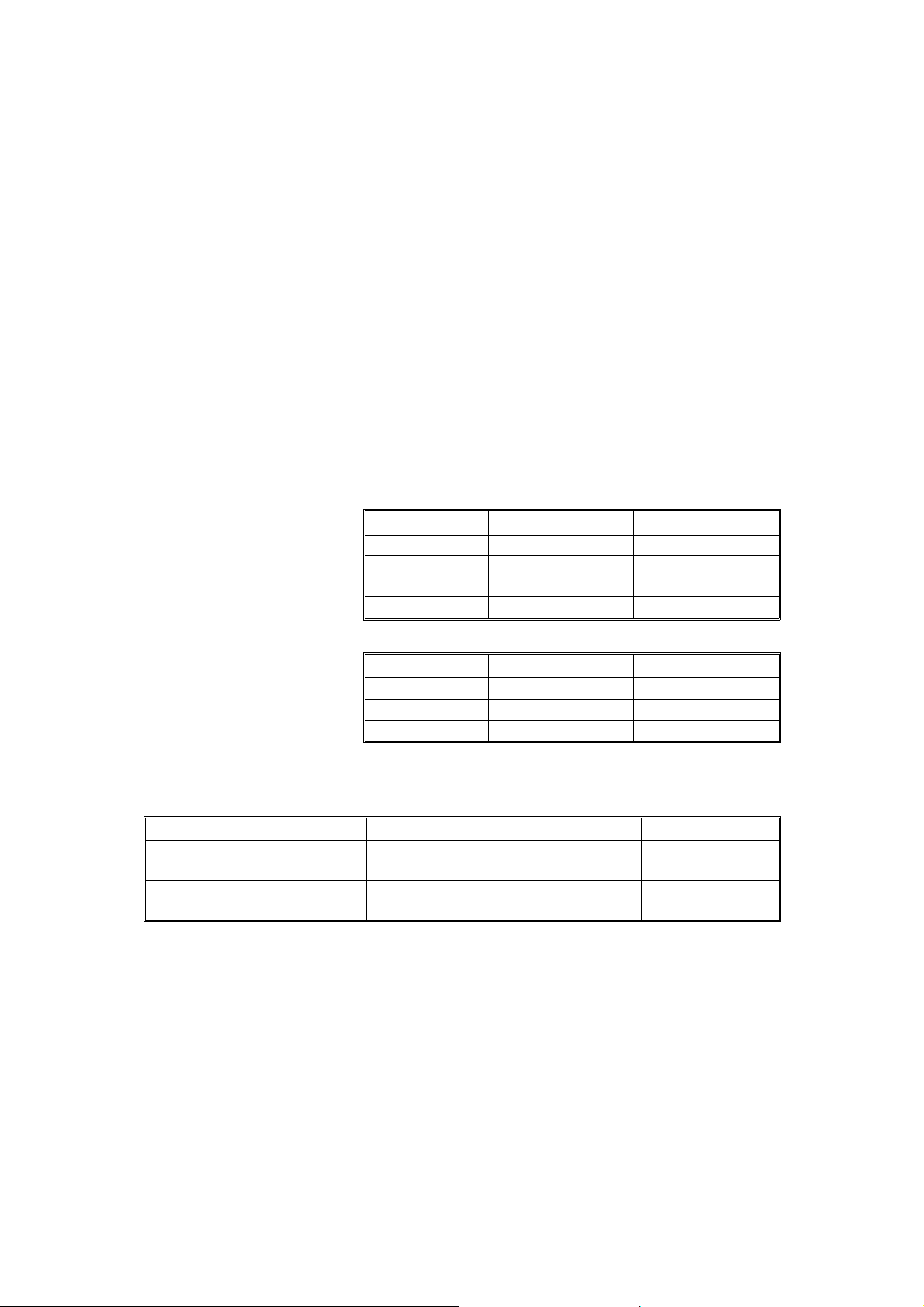
A4 Version Letter Version
Enlargement
141%
122%
Full size 100% 100%
93%
Reduction
82%
71%
Zoom: From 61% to 141% in 1% steps
(FT3213 copier only)
Copying Speed: 13 copies/minute (A4/8
10 copies/minute (B4/8
" x 11" lengthwise)
1/2
" x 14")
1/2
Warm-Up Time: 30 seconds (at 20°C/68°F)
First Copy Time: 9 seconds (A4/8
" x 11" lengthwise)
1/2
Copy Number Input: Number keys, 1 to 99
Manual Image Density: 7 steps
Toner Type: Type 320
129%
121%
93%
74%
65%
Developer Type: Type 310
FSM 1-1 A151/A152
Page 28
Automatic Reset: 1 minute standard setting; can also be set to 3
minutes or no automatic reset.
Energy Saver Function: Automatic
Paper Capacity: Paper tray – 250 sheets
Bypass feed table – 1 sheet
Toner Repleni shme nt: Cartridge exchange (32 0 g/ cart ridg e)
Copy Tray Capacity: 100 sheets (B4/10" x 14" or smaller)
Power Source: 110V/ 60Hz/ 15A (for Taiwan)
115V/ 60Hz/ 15A (for North Amer ica)
220V – 240V/ 50Hz/ 8A (for Europ e)
220V/ 60Hz/ 8A (for Middle East)
220V/ 50Hz/ 8A ( for Asia)
(Refer to the serial number plate (rating plate) to
determine the power source required by the
machine.)
Power Consumptio n:
Copier Only With DF*
Maximum 1.4 kVA 1.5 kV A
Warm-up 620 VA (average) 640 VA (average)
Copy cycle 810 VA (average) 860 VA (average)
Ready 160 VA (average) 180 VA (average)
Noise Emission:
Copier Only With DF*
Maximum 58 db 60 db
Copy cycle Less than 55 db Less than 55 db
Ready Less than 39 db Less than 39 db
Dimensions:
Width Depth Height
Copier with platen cover and
copy tray
Copier with document feeder
and copy tray*
713 mm (28.1") 592 mm (23.3") 400 mm (15.7")
713 mm (28.1") 592 mm (23.3") 463 mm (18.2")
*NOTE: The document feeder can be installed only on the FT3213 copier.
FSM 1-2 A151/A152
Page 29

Weight: Copier only: 43 kg (94.8 lb)
With DF: 50 kg (110.2 lb)
Optional Equipment:
(Sales items)
Optional Equipment:
(Service items)
Document feeder (FT3213 copier only)
Key counter
Drum anti-condensation heater
Optics anti-condensation heater
Pre-transfer lamp
Optics cooling fan (for FT3013 copi er only)
• Specifications are subject to change without notice.
Model Designation: A151 = FT3013
A152 = FT3213
MACHINE
OVERALL
INFORMATION
FSM 1-3 A151/A152
Page 30

Page 31

GUIDE TO COMPONENTS
Page 32

Page 33

1. MECHANICAL COMPONENT LAYOUT
11
10
9
14
15
13
16
17
18
19
21 22 23
20
24 25
26
27
28
12
29
30
GUIDE TO
COMPONENTS
31
32
33
8
67
45
3
2
1
1. Semicircular Feed Rollers
2. Paper Tray
3. Registration Rollers
4. Transfer and Separation
Corona Unit
5. Pick-off Pawl
6. Cleaning Unit
7. Pressure Roller
8. Fusing Unit
9. Hot Roller
10. Exit Rollers
11. Copy Tray
12. Hot Roller Strippers
13. Exhaust Blower Motor
14. 3rd Mirror
15. 2nd Mirror
16. 1st Mirror
17. Ozone Filter
18. Used Toner Tank
19. Cleaning Blade
20. Quenching Lamp
21. Charge Corona Unit
22. Lens
23. 6th Mirror
24. Erase Lamp
25. Drum
26. 4th Mirror
27. 5th Mirror
28. Optics Cooling Fan Motor
(FT3213 Copier only)
29. Toner Supply Unit
30. Development Unit
31. 2nd Relay Rollers
32. By-pass Feed Table
33. 1st Relay Rollers
FSM 2-1 A151/A152
Page 34

2. ELECTRICAL COMPONENT LAYOUT
24
21
20
19
18
17
16
22
23
25
26
27
28
29
30
31
15
14
13
12
11
10
9
8
7
6
1. Paper Tray Switch
2. Relay Sensor
3. Registration Clutch
4. Optics Cooling Fan Motor
(FT3213 only)
5. Registration Sensor
6. Image Density Sensor
7. Power Pack-TC/SC
8. Operation Panel Board
9. Erase Lamp
10. Total Counter
11. Quenching Lamp
12. Fusing Lamp
13. Front Cover Safety Switch
14. Main Switch
15. Fusing Thermoswitch
16. Exit Sensor
17. Exhaust Blower Motor
18. Optics Thermofuse
5
4
3
19. Auto Image Density Sensor
20. Fusing Thermistor
21. Exposure Lamp
22. Lens Motor
(FT3213 copier only)
23. Scanner Home Position
Sensor
24. Optics Thermistor
25. Lens Home Position
Sensor
(FT3213 copier only)
26. Power Pack-CC/Grid/Bias
27. AC Drive Board
28. Fusing Triac (115 V only)
29. Scanner Motor
30. 4th/5th Mirror Home
Position Sensor
(FT3213 copier only)
31. 4th/5th Mirror Motor
(FT3213 copier only)
32. Main Motor Capacitor
2
1
32
33
34
35
36
37
38
33. Main Board
34. Main Motor
35. Toner Supply Clutch
36. DC Power Supply Board
37. Relay Roller Clutch
38. Paper Feed Clutch
A151/A152 2-2 FSM
Page 35

3. ELECTRICAL COMPONENT DESCRIPTIONS
Motors
SYMBOL NAME FUNCTION
Drives all the main unit components except for the
M1 Main Motor
M2 Scanner Motor Drives the scanners (1st and 2nd). (dc stepper) 29
M3 Lens Motor
M4
M5
M6
4th/5th Mirror
Motor
Optics Coo l i n g
Fan Motor
Exhaust Blower
Motor
optics unit and fans. (115/220–240 Vac [ac
synchronous])
Positions the lens according to the selected
magnification. (dc stepper)
…
FT3213 copier only
Positions the 4th/5th mirrors according to the
selected magnification. (dc stepper)
…
FT3213 copier only
Prevents built up of hot air in the optics cavity.
(24 Vdc)
…
FT3213 copier only
Removes heat from around the fusing unit and
moves the ozone built up around the charge
section to the ozone filter. (24 Vdc)
Magnetic Cl utch
SYMBOL NAME FUNCTION
MC1
Registration
Clutch
Drives the registration rollers. 3
INDEX
NO.
34
22
31
4
17
INDEX
NO.
GUIDE TO
COMPONENTS
Magnetic Spring Clutches
SYMBOL NAME FUNCTION
MSC1
MSC2
MSC3
Toner Supply
Clutch
Relay Roller
Clutch
Paper Feed
Clutch
Drives the toner supply roller. 35
Drives the 1st and 2nd relay rollers. 37
Starts paper feed. 38
INDEX
NO.
FSM 2-3 A151/A152
Page 36

Switches
SYMBOL NAME FUNCTION
SW1 Main Switch Supplies power to the copier. 14
SW2
SW3
Front Cover
Safet y Switch
Paper Tray
Switch
Cuts the ac power line, when the front cover is
open.
Detects when the paper tray is set. 1
Sensors
SYMBOL NAME FUNCTION
S1
S2
S3
S4
S5 Exit Sensor Detects misfeeds. 16
S6 Relay Sensor
S7
S8
Scanner Home
Position Sensor
Lens Home
Position Sensor
4th/5th Mirror
Home Position
Sensor
Registration
Sensor
Image Density
(ID) Sensor
Auto Image
Density Sensor
(ADS)
Informs the CPU when the 1st scanner is at the
home position.
Informs the CPU when the lens is at the home
position (full size position).
…
FT3213 copier only
Informs the CPU when 4th/5th mirrors assembly is
at the home position (full size position).
…
FT3213 copier only
1) Detects misfeeds.
2) Controls the relay roller clutch stop timing.
1) Detects when copy paper is set on the
by-pass feed table.
2) Detects misfeeds.
Detects the density of the image on the drum to
control the toner density.
Senses the background density of the original. 19
INDEX
NO.
13
INDEX
NO.
23
25
30
5
2
6
Printed Circuit Boards
SYMBOL NAME FUNCTION
PCB1 Main Board
PCB2 AC Drive Board
PCB3
PCB4
A151/A152 2-4 FSM
DC Power
Supply Board
Operation Panel
Board
Controls all copier functions both directly and
through the other PCBs.
Drives the main motor, exposure lamp, fusing
lamp, and quenching lamp.
Converts the wall outlet ac power input to +5 volts,
+24 volts, and a zero cross signal.
Informs the CPU of the selected modes and
displays the copier status and condition on the
panel.
INDEX
NO.
33
27
36
8
Page 37

Lamps
SYMBOL NAME FUNCTION
L1 Exposure Lamp
L2 Fusing Lamp Provides heat to the hot roller. 12
L3 Quenching Lamp
L4 Erase Lamp
Applies high intensity light to the original for
exposure.
Neutralizes any charge remaining on the drum
surface after cleaning.
Discharge the drum outside of the image area.
Provides leading/trailing edge erase and side
erase.
INDEX
NO.
21
11
9
Power Packs
SYMBOL NAME FUNCTION
P1
P2
Power Pack
–CC/Grid/Bias
Power Pack
–TC/SC
Provides high voltage for the charge corona, grid,
and development roller.
Provides high voltage for the transfer and
separation corona.
Counter
SYMBOL NAME FUNCTION
CO1 Total Counter Keeps track of the total number of copies made. 10
Others
SYMBOL NAME FUNCTION
TH1
TH2
TS
TF
C
TR Fusing Triac
Fusing
Thermistor
Optics
Thermistor
Fusing
Thermoswitch
Optics
Thermofuse
Main Motor
Capacitor
Monitors the fusing temperature. 20
Monitors the optics temperature. 24
Provides back-up overheat protection in the fusing
unit.
Provides back-up overheat protection around the
exposure lamp.
Start capacitor. 32
Switches the fusing lamp on and off. (115 V only)
Note: In the 220V-230V/240V version, the triac
is built-in the ac drive board
INDEX
NO.
26
7
INDEX
NO.
INDEX
NO.
15
18
28
GUIDE TO
COMPONENTS
FSM 2-5 A151/A152
Page 38

4. DRIVE LAYOUT
G13
G14
G15
G16
G17
G18
G19
G1: Ma in Mot or Gear
BP6 BP5
G22 BP1G21G20
G26
G25
TB2
TB3
TB1
BP2
G12 G11
G10
G23
G2G1
G9
G8
G7
G6
G5
G4
G3
BP4
BP3
G24
G9
G8
G2
G1
G2: Relay Gear
G23: Timing Belt Drive
Gear
BP1: Timing Belt Pulley
TB1: Timing Belt
A
G10 Relay gear
G11: Timing Belt Drive Gear
BP5: Timing Belt Pul le y
TB3: Timing Belt
Development Section
BP6: Timing Belt Pul le y
G12: Development Gear
Development Unit
G13: Relay Gear
G14: Toner Supply CL Gear
Toner Supply CL
Toner Supply Unit
G8: Relay Gear
G9: Relay Gear
B
Cleaning Unit
G3: Fusing Drive Gear
Fusing and Exit Unit
G4: Hot Roller Gear
G7: Relay Gear
G6: Relay Gear
G5: Exit Roller Gear
A151/A152 2-6 FSM
Page 39

G15: Registration CL
Gear
Registration CL
Registration Rollers
G20: Relay Gear
G17: Relay Roller CL
Gear
Relay Roller CL
G16: 2nd Relay Roller
Gear
A
Paper Feed Section
BP2: Timing Belt Pulley
G22: Relay Gear
Paper Feed Section
G21: Paper Feed CL
Gear
Paper Feed CL
Feed Rollers
B
G24: Timing Belt Drive
Gear
BP3: Timing Belt Pul ley
TB2: Timing Belt
BP4: Timing Belt Pul ley
G25: Relay Gear
G26: Drum Drive Gear
GUIDE TO
COMPONENTS
2nd Relay Rollers
G18: Relay Gear
G19: 1st Relay Roller
Gear
1st Relay Rollers
FSM 2-7 A151/A152
Page 40

Page 41

INSTALLATION
Page 42

Page 43

1. INSTALLATION REQUIREMENTS
1.1 ENVIRONMENT
1. Temperature Range: 10°C to 30°C (50°F to 86°F)
2. Humidity Range: 15% to 90% RH
3. Ambient Illumination: Less than 1500 lux (do not exposure to direct
sunlight)
4. Ventilation: Room of more than 20 m3. Room air should turn over at least
30 m3/hour/person.
5. Ambient Dust: Less than 0.15 mg/m3 (4 x 10⁻³ oz/yd3)
6. If the installation place is air-conditioned or heated, place the machine as
follows:
a) Where it will not be subjected to sudden temperature changes.
b) Where it will not be directly exposed to cool air from an air-conditioner
in the summer.
c) Where it will not be directly exposed to reflected heat from a space
heater in winter.
INSTALLATION
7 . Avoid placing the machine in an area filled with corrosive gas.
8. Avoid any places higher than 2000 meters (6500 feet) above sea level.
9. Place the machine on a strong and level base.
10. Avoid any area where the machine may be subjected to frequent strong
vibration.
1.2 MACHINE LEVEL
1. Front to back: Within 5 mm (0.2") of level
2. Right to left: Within 5 mm (0.2") of level
FSM 3-1 A151/A152
Page 44

1.3 MINIMUM SPACE REQUIREMENTS
10 cm (3.9")
30 cm (11.8")
70 cm (27.6")
60 cm (23.6")
1. Front: 70 cm (27.6")
2. Back: 10 cm (3.9")
3. Right: 60 cm (23.6")
4. Left: 30 cm (11.8")
NOTE: A space of at least 10cm (3.9") at the rear of the machine is
necessary for smooth air inlet into the machine.
1.4 POWER REQUIREMENTS
1. Input voltage level:
110 V/60 Hz : More than 15 A
115 V/60 Hz : More than 15 A (U.S. Version)
220–240 V/50 Hz : More than 8 A
220 V/60 Hz : More than 8 A
220 V/50 Hz : More than 8 A
2. Permissible voltage fluctuation: ±10%
3. Do not set anything on the power cord.
NOTE: a) Be sure to ground the machine. (Do not connect the
grounding wire to a gas pipe.)
b) Make sure the plug is firmly inserted in the outlet.
c) Avoid multi-wiring.
A151/A152 3-2 FSM
Page 45

2. INSTALLATION PROCEDURE
2.1 ACCESSORY CHECK
Check the quantity and condition of the accessories in the box according to
the following list:
1. Copy Tray........................................................1
2. Envelope for NECR (–17 Only).......................1
3. NECR..............................................................1
4. Operating Instructions (Except –27) ...............1
5. Decal–Symbol Explanation.............................1
6. User Survey Card (–17 Only) .........................1
NOTE: (-17 = U.S. Version)
INSTALLATION
FSM 3-3 A151/A152
Page 46

2.2 COPIER INSTALLATION PROCEDURE
[B]
[A]
1. Remove the strips of tape from the copier as shown.
2. Pull out the paper tray [A], then remove the foam block [B] and tapes.
Close the paper tray.
A151/A152 3-4 FSM
Page 47

[B]
[A]
[H]
[G]
[F]
[C]
[F]
[E]
INSTALLATION
[D]
[I]
[J]
3. Open the platen cover [A] and remove the pieces of tape & the lock pins
[B]. (FT3013 copier: 2 pins, FT3213 copier: 4 pins)
NOTE: Save the lock pins for future shipping use.
4. Open the front cover [C], and remove the foam block [D].
5. Remove the shipping retainer [E] and tape & seal [F].
NOTE: Save the shipping retainer for future shipping use.
6. Open the upper unit [G] by pressing the release lever [H] (See "Caution:"
below). Gently remove the shipping spacers [I] from both ends of the
transfer/separation corona unit [J]. Remove the strip of tape [K] and
close the upper unit.
CAUTION: Be sure to place and hold your left hand on top of the
upper unit while pushing the release lever to the right with
your right hand. The upper unit will raise with force, and
holding the upper unit will prevent it from lifting too rapidly.
FSM 3-5 A151/A152
Page 48

[C]
[A]
[F]
[B]
[E]
[D]
[F]
7. Remove the two screws as illustrated above and pull out the
development unit [A] by pulling the left side of the development cover [B]
and place it on a clean sheet of paper.
[G]
8. Remove the toner supply unit [C] from the development unit [D] (2 gold
colored screws).
NOTE: Make sure to remove only the indicated screws.
9. Shake the developer package [E] well, and pour one pack of developer
into the development unit while rotating the gears [F] on both sides to
distribute the developer evenly as shown in the illustration.
NOTE: This copier is not equipped with a knob on the paddle roller shaft
like other machines. When installing new developer or manually
rotating the development roller, always make sure to turn the
gears in the direction shown in the illustration above. The copier
might be damaged if they are turned in the opposite direction.
10. Reinstall the toner supply unit on the development unit.
NOTE: Make sure that there is no gap [G] between the toner supply unit
and the development unit. (See illustration.)
A151/A152 3-6 FSM
Page 49

[B]
[C]
[A]
CN421
220 ∼230V
240V
[A]
INSTALLATION
[E]
[D]
11. Reinstall the development unit.
12. Shake the toner cartridge [A] well and insert the cartridge while pulling off
the seal [B].
NOTE: Position the cartridge as shown in the a bove illustr ation when
inserting into copier.
13. Close the front cover.
CAUTION: This procedure (step 14) must be done only in 240 volt
areas.
14. Perform the conversion from 220 ∼ 230 V to 240 V as follows:
1) Remove the upper rear cover [C] (2 screws).
2) Disconnect the short connector [D] (2P/White) on the ac drive board
[E] from CN421 and reconnect it to CN421 as shown in the illustration.
3) Reinstall the upper rear cover.
FSM 3-7 A151/A152
Page 50

4) Plug in the machine and turn on the main switch, then lower the platen
cover.
5) Enter the SP mode as follows:
a) Enter "71" using the numeral keys.
b) Press and hold the Clear/Stop key until a dot (•) appears in the top
left corner of the copy counter.
c) Release the Clear/Stop key and again press the Clear/Stop key.
d) Press the Lighter key.
6) Perform SP 12 as follows:
SP Mode Number Procedure
Enter "12" using the numeral keys. Then, press
the Auto Image Density key.
Conversion from
12
220 ∼ 230V to
240V.
Change the data from "0" to "1" using numeral
key.
Then, press the Auto Image Density key.
"12" will start blinking.
Go to the step 15. 3).
15. Perform the developer initial setting.
1) Plug in the machine and turn on the main switch, then lower the platen
cover.
2) Enter the SP mode as follows:
a) Enter "71" using the numeral keys.
b) Press and hold the Clear/Stop key until a dot (•) appears in the top
left corner of the copy counter.
c) Release the Clear/Stop key and again press the Clear/Stop key.
d) Press the Lighter key.
3) Perform SP 65 as follows:
SP Mode Number Procedure
Enter "65" using the numeral keys and press the
Developer Initial
65
Setting
Auto Image Density key. "50" will be displayed
in the copy counter. Press the Start key for
initial setting.
A151/A152 3-8 FSM
Page 51

[A]
[C]
[A]
[B]
INSTALLATION
[D]
[E]
16. Place the symbol explanation decal [A] on the platen cover as shown, or
when the DF [B] is installed on the machine, place the decal on the DF
as shown.
17. Install the copy tray [C].
18. Load paper into the paper tray [D] according to the instructions on the
paper tray.
19. Change the paper size plate [E] to display the correct paper size.
20. Check the machine operation and copy quality.
FSM 3-9 A151/A152
Page 52

2.3 KEY COUNTER HOLDER INSTALLATION (OPTION)
[D]
[C]
[E]
NOTE: To install the key counter holder, the following parts are required.
• Key counter bracket [A]
• Key counter harness [B]
• Two M3X6 sunken head screws [C]
1. Turn off the main switch.
2. Open the front cover.
3. Open the upper cover by pressing the release lever.
[F]
[B]
[A]
NOTE: Be certain to hold the upper unit while releasing.
4. Remove the right cover (2 screws).
5. Cut off the key counter cover on the right cover with a pair of pliers.
6. Remove the upper rear cover (2 screws).
7. Install the key counter harness [B] to CN121 on the main board.
8. Connect the 4P connector [D] of the key counter holder [E] to the key
counter harness [B] through the key counter access hole.
9. Position the key counter bracket [A] as shown in the illustration and
insert the key coun ter holder.
10. Align the holes in the key counter bracket with the mounting holes of the
key counter holder and secure the key counter holder (2 screws).
NOTE: The fixing plate has three different hole sizes. Use the holes that
match those on the counter that you are installing.
11. Cut the jumper wire (JP101) [F] with a pair of diagonal cutters or other
suitable tool.
12. Reinstall all covers.
A151/A152 3-10 FSM
Page 53

SERVICE TABLES
Page 54

Page 55

1. SERVICE REMARKS
1.1 GENERAL CAUTION
1. To prevent physical injury, keep hands away from the mechanical drive
components when the main switch is on (especiall y durin g the warm- up
cycle). If the Start key is pressed before the copier finishes the warm-up
cycle, (Start indicato r starts blinking) the copier starts making copies as
soon as the warm-up cycle is completed.
2. When the development unit, cleaning unit, drum unit or the DF is
removed from the machine, the upper unit becomes lighter. If the upper
unit is released under this condition, it tends to open very abruptly. The
service engineer might be injured if he is leaning over the machine at this
time. Also, the machine might move due to the shock of the upper unit
opening abruptly. To avoid possible injury or machine damage, hold the
upper unit firmly when opening the unloaded upper unit.
3. Even with the above mentioned components installed the upper unit can
open rather rapidly. Due to this possibility it is important to always hold
the upper unit with one hand when releasing it from the lower unit. It is
also important that the operator also be familiar with the proper method
of releasing the upper unit. This condition is not a concern if the DF is
installed to the FT3213.
4. Due to variation in the tolerance of the torsion springs, the upper unit
cannot hold at an angle of 16 degrees by itself when the DF is installed.
To avoid possible injury, always use the upper unit stand to keep the
upper unit open.
1.2 DRUM
The organic photoconductor drum is comparatively more sensitive to light
and ammonia gas than a selenium drum.
1. Never expose the drum to direct sunlight.
2. Never expose the drum to direct light of more than 1,000 Lux for more
than a minute.
3. Never touch the drum surface with bare hands. When the drum surface
is touched with a finger or becomes dirty, wipe with a dry cloth or clean
with wet cotton. Wipe with a dry cloth after cleaning with wet cotton.
4. Never use alcohol to clean the drum. Alcohol dissolves the drum surface .
5. Store the drum in a cool, dry place away from heat.
6. Take care not to scratch the drum as the drum layer is thin and can be
damaged.
TABLES
SERVICE
7. Never expose the drum to corrosive gases such as ammonia gas.
FSM 4-1 A151/A152
Page 56

8. Always keep the drum in the protective sheet when inserting or pulling
the drum unit out of the copier to avoid exposing it to bright light or direct
sunlight. This will protect the drum from light fatigue.
9. Before pulling out the drum unit, place a sheet of paper under the unit to
catch any spilled toner.
10. When installing a new drum, do the following:
a) Apply setting powder to the entire surface of the drum.
b) Perform the drum initial setting (SP66).
NOTE: This is not necessary at installation of a new machine as the
drum initial setting is performed at the factory.
c) Perform the Vsg adjustment (SP54).
11. Dispose of used drums according to local regulations.
1.3 CHARGE CORONA
1. Clean the corona wire by sliding the corona unit in and out. (The cleaner
pads come into contact with the corona wire when the corona unit is slid
all the way out.) The wire and casing can also be cleaned with water or
dry cloth. Do not use any abrasives or solvents.
2. Do not touch the corona wire and the grid plate with oily hands. Oil stains
may cause uneven image density on copies.
3. Make sure that the corona wire is correctly positioned between the
cleaner pads and that there is no foreign material on the casing.
4. When adjusting the charge corona current, always make sure that the
center of the drum shoe is aligned with the middle of the corona wires.
5. Clean the charge grid with a blower brush (not with a cloth).
6. The corona height should only be adjusted in the following two cases:
a) When the front end block is replaced
b) When the drum charge current is uneven
A151/A152 4-2 FSM
Page 57

1.4 OPTICS
1. The position of following parts are very difficult to adjust. Do not adjust
them.
a) 4th/5th Mirror Home Position Sensor
b) Lens Home Position Sensor
c) Lens and 4th/5th Mirror Guide Rails
NOTE: Before removing a sensor bracket to replace a sensor, mark the
position of the bracket. Check the copy image (magnification and
focus)to confirm that the sensor bracket has been properly
repositioned.
2. Clean the exposure glass with glass cleaner and a dry cloth to reduce
the amount of static electricity on the glass surface.
3. When reinstalling the exposure glass, make sure that the red mark on
the edge of the glass is positioned on the right hand side facing upward.
This side has received a special treatment to make it smoother and
generate less static electricity. This is especially important when the DF
is installed.
4. Clean the following parts with a dry cloth:
a) Lens and 4th/5th Mirror Guide Rails
b) Scanner Guide Plates
5. Only use a clean soft cloth damped with alcohol or water to clean the
mirrors and lens.
6. Do not touch the following parts with your bare hands:
a) Reflectors
b) Exposure Lamp
c) Mirrors and Lens
7. Whenever one of the actions listed bel ow need s to be perform ed, all the
following actions must be done in order.
a) Optics cleaning
b) SP95 (VL Correction Reset)
c) SP48 (Light Intensity Adjustment)
d) SP56 (ADS Reference Voltage Adjustment)
8. Do not adjust VR401 on the AC drive board.
TABLES
SERVICE
FSM 4-3 A151/A152
Page 58

1.5 DEVELOPMENT
1. Be careful not to nick or scratch the development roller sleeve.
2. Place the development unit on a sheet of paper after removing it from the
copier. This prevents any small metal objects (staples, paper clips,
E-rings, etc.) from being attracted to the development roller and getting
inside the unit.
3. Never loosen the two screws securing the bias terminal block. The
position of the terminal block is set with a special tool and instr ume nt at
the factory to ensure the proper gap between the drum and the
development roller.
4. Never loosen the three screws securing the doctor plate and the four
screws securing the doctor plate mounting bracket. The position of the
doctor plate is set with a special tool at the factory to ensure the proper
gap between the doctor blade and the development roller.
5. Clean the drive gears after removing used developer.
6 . Developer initial setting (SP65) is necessary when the developer is
replaced.
7. Dispose of used developer according to lo cal regula ti ons.
8. When installing new developer or manually rotating the development
roller, always make sure to turn the gears in the direction shown in Sec.
5 (Developer Replacement). The copier might be damaged if they are
turned in the opposite direct i on.
1.6 TONER SUPPLY
1. Clean the image density sensor with a blower bru s h.
2. Do not touch the sensor pattern with bare hands.
3. Image density sensor adjustment (Vsg Adjustment [SP54]) is required in
the following cases:
a) When the image density sensor is replaced
b) When the main board is replaced
c) When the drum has been replaced and Vsg is out of specification
d) When there have been problems with toner supply and Vsg is out of
specification
A151/A152 4-4 FSM
Page 59

1.7 TRANSFER AND SEPARATION
1. Clean the corona wires and casing with wat er or dry cloth.
2. When adjusting the corona current, always make sure that the center of
the drum shoe is aligned with the corona wire.
1.8 CLEANING UNIT
1. Be careful not to damage the edge of the cleaning blade.
2. After installing a new cleaning blade, be sure to apply setting powder
evenly on the surface and edge of the blade.
3. The bottom plate of the cleaning unit may be hot from the heat of the
fusing unit. Remove the unit by supporting your left hand on the cushion
attached under the bottom plate.
4. When inserting the cleaning unit into the copier, be sure that the cleaning
unit rail is properly engaged with the unit guide rail on the copier.
5. Empty the used toner tank every service call and clear the toner end
counter (SP58) by SP83 (toner end counter clear ) . Esp ecial ly, since the
FT3013 copier does not have side erasing by the erase lamp, the used
toner tank may become full in a faster period than expected under
certain conditions.
6. Do not perform toner end counter cl ear (SP83) without emp t ying the
used toner tank.
TABLES
SERVICE
7. Dispose of used toner according to local regulation s.
1.9 FUSING UNIT
1. Be careful not to damage the edges of the hot roller strippers or their
tension springs.
2. Do not touch the fusing lamp with bare hands.
3. Make sure that the fusing lamp does not touch the inner surface of the
hot rol ler.
FSM 4-5 A151/A152
Page 60

1.10 PAPER FEED
1. Do not touch the feed and relay rollers with oily hands.
2. A worn out registration roller can crease paper. Worn rollers should be
replaced.
3. The side fences and the end fence of the paper tray should be positioned
correctly so that they securely hold the paper. Otherwise, paper misfeeds
may occur.
1.11 DOCUMENT FEEDER
1. When installing or removing the document feeder, make sure that the
document feeder is in the open position.
2. A build-up of static electricity on the exposure glass can cause originals
to misfeed. Apply a small amount of silicon oil to the glass using a clean
cloth lightly dampened with silicon oil. This will reduce the amount of
friction.
1.12 OTHERS
1. When replacing the main board, remove the RAM pack from the old main
board and place it on the new main board. Then install the new main
board in the copier.
2. After installing a new main board with a new RAM pack, the Clear All
Memory (SP99) procedure (see page 4-10) must be performed. (Do not
perform SP99 if you have placed the old RAM pack on the new main
board.)
3. Never perform SP99 (Clear All Memory) except for the following two
cases:
a) When the copier malfunctions due to a damaged RAM pack.
b) When replacing the RAM pack.
4. Whenever SP99 (Cle ar All Mem or y) is perfor med , all the steps of the
procedure must be followed. Otherwise, copy quality might be seriously
affected.
5. When replacing a sensor, do not overtight en the screws. Thi s may
damage the sensor.
6. If a customer reports that red image areas on the original do not appear
on the copy, instruct the customer to select the desired image density by
the Manual Image Density keys.
A151/A152 4-6 FSM
Page 61

7. Tighten securely the screws used for grounding the following PCBs
when reinstalling them.
• AC Drive Board • DC Power Supply Board
• TC/SC Power Pack • CC/Grid/Bias Power Pack
8. The RAM pack must be handled as follows:
WARNING: The RAM pack has a lithium battery which can explode if
handled incorrectly. Replace only with the same type RAM
pack. Do not recharge, or burn this battery. Used RAM
pack must be handled in accordance with local
regulations.
TABLES
SERVICE
FSM 4-7 A151/A152
Page 62

2. SERVICE PROGRAM MODE
2.1 SERVICE PROGRAM MODE OPERATION
The service program (SP) mode is used to check electrical data and change
modes or adjustment values.
2.1.1 Service Program Access Procedure
There are two ways to access an SP mode.
(1) By the operation panel
(2) By turning on DPS101-2 on the main board
All SP modes except for SP98, and SP99 can be accessed by key operation.
When accessing SP98, and SP99, JPS101-C must be short-circuited.
Access Procedure 1–Using The Oper ation Panel
1. Turn on the main switch.
2. Enter "71" by using the numeral keys.
3. Press and hold the Clear/Stop key until a dot (•) appears in the top left
corner of the Copy Counter and then release it.
4. Press the Clear/Stop key again and then press the Lighter key.
NOTE: "5" will blink in the Copy Counter to show that the SP mode has
been accessed.
5. Enter the desired SP mode number using the numeral keys. The SP
mode numbers are given in the Service Program Mode Table.
NOTE: "•" is displayed instead of "1" in the Copy Counter when SP
mode numbers over "100" ar e entered. The maximum number is
"127".
6. Press the Auto Image Density key to view the data.
NOTE: To enter a different SP mode number, press the Auto Image
Density key again.
7. To leave SP mode, open and close the front cover or turn the main
switch off and on.
A151/A152 4-8 FSM
Page 63

Access Procedure 2 - Using DPS101-2
1. Turn the main switch off.
2. Remove the upper rear cover and turn on DPS101-2, then turn on the
main switch. "5" will blink in the Copy Counter.
3. Enter the desired SP mode number by the numeral keys. SP mode
numbers are given in the Service Program Mode Table.
4. Press the Auto Image Density key to view the data.
5. To leave SP mode, turn off DPS101-2.
NOTE: To cancel an already entered SP mode, press the Auto Image
Density key.
2.1.2 Change Adjustment Values or Modes
1. Follow the steps from 1 to 6 in Access Procedure 1 or the steps from 1 to
4 in access procedure 2.
2. The factory-set or the default setting will be displayed in the
Magnification indicator (FT3213 copier) or in the Copy Counter (FT3013
copier).
3. Enter the desired value or mode using the numeral keys and then press
the Auto Image Density key. (SP mode data are given in the Service
Program Mode Table.)
4. To leave SP mode, open/close the front cover or turn off/on the main
switch (Access Procedure 1) or turn off DPS 101-2 (Access Procedure 2).
TABLES
SERVICE
FSM 4-9 A151/A152
Page 64

2.1.3 Memory Clear Procedure
– Clear Counters (SP98) –
NOTE: This SP mode clears the following counters:
• SP88: PM Counter Display
• SP100: By-pass Feed Copies
• SP101: Paper Tray Copies
• SP103: Total Copi es
• SP106: DF Originals
• SP110: Total Misfeed s
• SP111: Number of Misfeeds by Location
• SP120: Total Service Calls
• SP121: Optics Section Service Calls
• SP122: Exposure Lamp Se rvice Cal ls
• SP124: Fusing Section Service Calls
• SP125: DF Communication Service Calls
1. Turn off the main switch.
2. Turn on DPS101-2 and short-circuit JPS101-C (Lower).
3. Turn on the main switch.
4. Enter "98" by the numeral keys and then press the Auto Image Density
key to view data.
5. Enter "1" by the numeral key and then press the Auto Image Density key.
NOTE: The data "1" blinks 4 times when the above procedure is
completed.
6. Turn off the main switch.
7. Turn off DPS101-2 and open-circuit JPS101-C (Lower).
A151/A152 4-10 FSM
Page 65

– Clear All Memory (SP99) –
CAUTION: Memory all clear mode (SP99) clears all the correction data
for process control and software counters, and returns all
the modes to the default settings. Normally, SP99 should
not be used.
This procedure is required only when the copier
malfunctions due to a damaged RAM Pack or when
replacing the RAM Pack for any reason.
1. Turn off the main switch.
2. Turn on DPS101-2 and short-circuit JPS101-C (Lower).
3. Turn on the main switch.
4. Enter "99" by the numeral keys and then press the Auto Image Density
key to view data.
5. Enter "1" by the numeral key and then press the Auto Image Density key.
NOTE: The data "1" blinks 5 times when the above procedure is
completed.
6. Clean the used toner tank since the toner end counter has been cleared.
(See Used Toner Removal.)
CAUTION: Skipping this step will cause the used toner overflow
condition not to be detected properly.
7. Replace the OPC drum with a new one. (See Drum Replacement.)
CAUTION: Since the drum motor rotation time (SP57) for the drum
wear correction has been cleared, the old drum cannot be
used. If the old drum is used after all memory is cleared,
dirty background may occur.
8. Load new developer. (See Developer Replacement.)
NOTE: Since the software counter for the development bias voltage in
the toner detection cycle has been cleared, –20 volts will be
applied to the development roller for the initial 499 copies.
9. Clean the optics, sensors, and inside of the copier if necessary.
10. Refer to the "FACTORY SETTING" table located inside the upper slit of
the inner cover and enter the data for:
(1) SP60: Standard Image Grid Voltage Setting
(2) SP62: Standard ID Sensor Grid Voltage Setting
TABLES
SERVICE
FSM 4-11 A151/A152
Page 66

10. Perform the following SP modes in sequence:
(1) SP66: Drum Initial Setting
(2) SP65: Developer Initial Setting
(3) SP48: Light Intensity Adjustment
(4) SP56: ADS Voltage Adjustment
(5) SP54: Vsg Adjustment
(6) SP42: Registration Adjustment
(7) SP41: Leading Edge Erase Mar gin Ad justm ent
(8) SP43: Vertical Magnification Adjustment
(9) SP44: Horizontal Magnification Adjustment (FT3213 copier only)
(10) SP47: Focus Adjustment (FT3213 copier only)
11. Turn off the main switch.
12. Turn off DPS101-2 and open-circuit JPS101-C (Lower).
A151/A152 4-12 FSM
Page 67

2.2 SERVICE PROGRAM MODE TABLE
Rev. 1/26/96
1. A "❐" after the mode name means that copies can be made while in the
SP mode. (Copies can be made by pressing the Start key after pressing
the Auto Image Density key.)
2. In the
3. In the
Function
Data
column, comments (extra information) are in italics.
column, the default value is printed in bold letters.
4. In some SP modes, data display is different between the FT3013 and
FT3213 models because of the difference in the operation panel. After
entering the desired SP mode number, refer to the notes written at the
end of the table to correctly observe the displayed data. (Which note to
refer is described inside the Function column.)
Mode No. Function Data
⇒
5 Exposure Lamp
❐
OFF
6 Misfeed
Detection Off
7 Aging Mode Factory use.
8 Input Check
9 Output Check Electrical components turn on. For data, see
11 All Indicators
ON
12 220-230V /240V
Conversion
14 Auto "OFF" Auto-off mode can be selected
15 Auto Reset
Time (Energy
Saver Mode)
16 Count Up/Down Selects count up or count down.
17 Open No function.
18 Reduce/Enlar ge
Key Function
(FT3213 copier
only)
Exposure lamp OFF
Turn on DPS101-1, then press the Start key to
start free run. Press the C/S key to stop free run.
Press the Auto Image Density key in Ready
mode to turn off this mode.
Use this mode for the scanner movement check.
To save toner, remove the development unit.
Copies are made without misfeed detection.
Press the Start key to make a copy. Press the
❐
Auto Image Density key in Ready mode to turn
off this mode.
Use this mode to check whether the paper
misfeed was caused by a sensor malfunction.
The total counter increments when copies are
made in this mode.
❐
Displays the input data from sensors and
switches.
Turns on all the indicators on the operation panel.
To turn off the indicators, press the Auto Image
Dens ity k ey.
Selects 220-230 or 240 volts.
If the rated voltage is 240V, this data must be
changed to "1".
Selects auto reset time of 1 or 3 minutes, or
cancels this mode.
The copier automatically goes to the energy
saver mode at the selected reset time when
SP78 is set to "1".
Specifies whether reduction or enlargement is
selected first when the Reduce/Enlarge key is
pressed.
Refer to NOTE 2.
For data, see
page 4-20.
page 4-21.
0: 220-230V
1:240V
0: 30 mins
(default)
1: 15 mins
2: 1 hour
3: 1.5 hours
4: 2 hours
0: 1 min.
1: 3 min.
2: None
0: Up
1: Down
0: Reduction
1: Enlargement
TABLES
SERVICE
FSM 4-13 A151/A152
Page 68

Mode No. Function Data
19 ADS Priority Specifies whether the copier defaults to ADS or
manual mode when the main switch is turned on.
29 Fusing
Temperature
Control
Selects fusing temperature control mode.
After selecting the control mode and turning the
main switch off/on, the fusing temperature
control is changed.
30 Toner Supply
Mode
31 Toner Supply
Ratio
(Detect Mode)
32 Toner Supply
Ratio
(Fixed Mode)
33 ID Sensor Bias Sets the bias voltage applied to the development
Selects toner supply system.
See SP31/SP32 for toner supply amount.
Determines how much toner is supplied in detect
mode.
Determines how much toner is supplied in fixed
mode.
roller for the ID Sensor Pattern.
0: Vo
1: Vo+40V
2: Vo–20V
3: Vo–40V
34 ADS Level Selects the image density level in ADS mode.
Data: 1
Increases grid voltage (–40V). Development bias
voltage is not changed.
Data: 2
Increases development bias voltage (–40V). Grid
voltage is not changed.
35 ID Detec ti o n
Interv a l
ID sensor check is performed every 5 copies or
10 copies.
If low image density occurs in the near end
condition, change the data to "1".
37 Image Bias
Adjustment
Adjusts image bias output if the image density at
level 4 cannot be adjusted by Light Intensity
adjustment (SP48).
0: Vo
1: Vo+40V
2: Vo+20V
3: Vo–20V
4: Vo–40V
39 Ex posure LampONFactory use.
0: ADS
1: Manual
0: ON/OFF
control
1: Phase control
0: Detect Mode
1: Fixed Mode
0: 15%
1: 7%
2: 30%
3: 60%
0: 7.0%
1: 3.5%
2: 10.5%
3: 14.0%
Toner Density
0: Normal (Vo)
1: Low
2: High
3: Higher
0: Normal
1: Darker
2: Lighter
0: 10 copies
1: 5 copies
0: Normal (Vo)
1: Darkest
2: Darker
3: Lighter
4: Lightest
41 Lead Edge
Erase Margin
Adjustment
42 Registration
Adjustment
43 Vertic al
Magnification
Adjustment
A151/A152 4-14 FSM
Adjusts the lead edge erase margin. 0–15
0.4 mm per step. (–3.2 mm to +2.8 mm)
❐
Adjusts registration. 0–15
❐
0.4 mm per step. (+3.2 mm to –2.8 mm)
Adjusts magnification in the paper travel
direction.
❐
0.2% per step. (–1.6% to +1.4%)
Default = 8
Default = 8
0–15
Default = 8
Page 69

Mode No. Function Data
44 Horizontal
Magnification
Adjustment
(FT3213 copier
❐
only)
45 Registration
Buckle – Paper
❐
Feed
47 Focus
Adjustment
(FT3213 copier
❐
only)
48 Light Intensity
Adjustment
Adjusts magnification perpendicular to the
direction of paper travel.
0.2% per step. (–1.6% to +8.4%)
Adjust the amount of paper buckle in registration
area.
0.4 mm per step. (–3.2 mm to +2.8 mm)
Adjusts the 4th/5th mirror position to correct
focus.
This mode must be done after horizontal and
vertical magnification adjustment (SP43 and 44).
Adjusts the exposure lamp voltage. 100–145
❐
Before performing this mode, clean the optics
and perform SP95. After performing this mode,
perform SP56. The exposure lamp voltage is
adjusted on the production line.
Refer to NOTE
3 for FT3013 copier.
50 Image Bias
Adjustment at
ID Level 7
❐
Adjusts image bias voltage at ID level 7.
0: Vo
1: Vo+40V
2: Vo–40V
3: Vo–80V
51 Ex posure Lamp
Data Display
Displays the exposure lamp data with a
reference number.
The exposure lamp, and optics cooling fans turn
on for 10 seconds when the Auto Image Density
key is pressed. Press the C/S key to turn this
mode off. Do not repeat more than 5 times to
avoid overheating the optics cavity.
Refer to
NOTE 3 for FT3013 copier.
52 Fusing
Temperature
Display
54 Vsg Display Displays Vsg.
Displays the fusing temperature.
Refer to NOTE 3 for FT3013 copier.
Adjust Vsg to 4.0 ± 0.2 V using VR102 on the
main board. The main motor and the ID sensor
LED turn on when the Auto Image Density key is
Refer to NOTE 4 for FT3013 copier.
55 Vsg & Vsp
Display
❐
pressed.
Displays the Vsg and Vsp readings.
The Vsg reading is displayed while the "0" key is
held down. FT3013 copier displays the Vsp
reading while the "1" key is held down. To stop
this mode, press the C/S key.
The Vsp and Vsg voltage readings are updated
every 10 or 5 copies depending on SP35
selection. In free run mode, the Vsg and Vsp
readings are updated every copy cycle.
Refer to
NOTE 4 for FT3013 copier.
0–50
Default = 8
0–15
Default = 8
0–100
Default = 40
Default = 126
0: Normal (Vo)
1: Darker
2: Lighter
3: Lightest
100–150
TABLES
SERVICE
FSM 4-15 A151/A152
Page 70

Mode No. Function Data
56 ADS Reference
Voltage Display
Displays ADS reference voltage.
Before performing this mode, clean the optics,
perform SP95 and SP48.
After adjusting the light intensity (SP48), place 5
sheets of A3 (LDG) white paper on the exposure
glass and select this mode. Adjust ADS voltage
to 2.5
0.1 V using VR101 on the main board.
±
Refer to NOTE 4 for FT3013 copier.
57 Drum Rotation
Time
Displays the total time that the drum has rotated.
"Minute" is displayed first. Press and hold the
Lighter key to display "Hour".
58 Toner End
Counter
Displays the toner end condition count.
The toner end counter counts up 1 after 200
copies are made following toner cartridge
replacement.
59 Open No function.
60 Standard
Image Grid
Voltage Setting
61 Standard ID
Sensor Bias
Voltage Setting
62 Standard ID
Sensor Grid
Voltage Setting
63 Open No function.
64 Toner Density
Level Display
Factory use.
Do not change data.
Refer to NOTE 6.
Factory use.
Do not change data.
Factory use.
Do not change data.
Refer to NOTE 6.
Displays the toner density level detected by
initial setting (SP65).
Data Vsp/Vsg(%)
0: 12–15
1: 0–7
2: 8–11
3: 16–21
4: 22–100
65 Developer
Initial Setting
Agitates new developer for about 5 minutes.
"50" is displayed on the copy counter when the
Auto Image Density key is held down. Press the
Start key to start the initial setting.
Initial setting must be done when new
developer is installed.
The copier automatically returns to normal mode
after initial setting is completed.
66 Drum Initial
Setting
Used to set new drum condition.
Initial setting must be done when a new drum
is insta lled.
The Drum Rotation Time (SP57) and the OPC
counter (SP69) are cleared.
0–8
Default = 4
0–8
Default = 2
0–8
Default = 4
0–4
0: No
1: Yes
A151/A152 4-16 FSM
Page 71

Mode No. Function Data
67 Vr Ratio Display Displays the present Vr ratio. 0–100
L = Vrp/Vsg x 100
L (%) Grid voltage
100 to 84 Vo
83 to 58 Vo–40V
57 to 41 Vo–80V
40 to 28 Vo–120V
27 to 0 Vo–160V
Refer to NOTE 3 for FT3013 copier.
68 Vr Forced
Detection
Detects Vrp and perform Vr correction.
1. Turn off the DPS 101-2 after pressing the
0: No
1: Yes
Auto
Image Density key if it is on.
2. Make 5 copies.
69 OPC Counter Shows the total number of copies made with the
drum installed on the machine.
Refer to NOTE 5.
78 Auto Energy
Saver Mode
79 Fusing
Temperature
Adjustment
(Maximum
temperature
during copying)
80 Open No function.
83 Toner End
Counter Clear
Selects the "Automatic Energy Saver" mode.
The copier automatically goes to Energy Saver
mode at the auto reset time selected (SP15).
Adjusts the maximum temperature of the hot
roller during copying.
188°C to 202°C in 1°C steps.
Refer to NOTE 3 for FT3013 copier.
Clears the toner end counter (SP58). Resets the
used toner overflow condition (E70) if it is
detected.
0: No
1: Yes
188–202°C
Default=198°C
0: No
1: Yes
This mode must be performed when the used
toner tank is cleaned.
86 Ener gy Saving
Ratio
Selects energy saving ratio.
The greater the saving ratio, the longer the
waiting time until the copier returns to the ready
condition.
0: 56%
1: 47%
2: 37%
3: 25%
Saving Ratio Waiting Time
0: 56% 25 sec.
1: 47% 19 sec.
2: 37% 12 sec.
3: 25% 5 sec.
87 PM Interval
Setting
88 PM Counter
Display
Sets the interval of the PM counter.
Displays contents of the PM counter.
Refer to NOTE 5.
When the PM counter
0: No PM
1: 40K
2: 60K
3: 80K
4: 100K
exceeds to the selected setting of SP87, the
Magnification indicator (FT3213 copier) or the
Copy Counter (FT3013 copier) blinks.
89 PM Counter
Clear
Resets the PM counter.
Use this mode after performing PM.
0: No
1: Yes
TABLES
SERVICE
FSM 4-17 A151/A152
Page 72

Mode No. Function Data
91 Optics Cooling
Fan Operation
(FT3013 copier
only)
93 Maximum Copy
Quantity
L
95 V
Correction
Reset
Enables the optics cooling fan (service option)
operation as FT3213 copier.
Refer to Section 6 for information.
Limits the maximum copy quantity that can be
entered.
Resets the exposure lamp data and counter for
L
correction.
the V
Before performing this mode, clean the optics
parts. After performing this mode, perform SP48
and SP56.
98 Clear Counters Clear the following counters:
Copy Counters
•
SC Counters
•
Misfeed Counters
•
PM Counter
•
To clear, turn on DPS101-2 and short-circuit
JPS101-C (Lower).
99 Clear Al l
Memory
Clear all counters and returns all modes to the
default setting.
To clear, turn on DPS101-2 and short-circuit
JPS101-C (Lower).
100 By-pass Feed
Copies
Displays the total number of copies fed from the
by-pass feed table.
Refer to NOTE 5.
101 Paper Tray
Copies
Displays the total number of copies fed from the
paper tray.
Refer to NOTE 5.
102 Open No function.
103 Total Copies Displays the total number of copies.
Refer to NOTE 5.
106 DF Originals
(FT3213 copier
only)
110 Misfeeds (total) Displays the total number of paper misfeeds.
Displays the total number of originals fed from
the DF.
Refer to NOTE 5.
Refer to NOTE 5.
111 Number of
Misfeeds by
Location
Displays the total number of paper misfeeds in
each area. Press the "1" key to select the
desired number.
Refer to NOTE 5.
"1" will be selected when the
Auto Image Density key is pressed.
1: Paper Feed
2: Exit
3: (Open)
4: DF
120 Total Service
Calls
121 Optics Section
Service Calls
122 Exposure Lamp
Service Calls
123 Open No function.
Displays the total number of times the service
call indicator has turned on.
Displays the total number of "optics section"
service calls.
Displays the total number of "exposure lamp"
service calls.
0: No
1: Yes
99
1–
0: No
1: Yes
0: No
1: Yes
0: No
1: Yes
A151/A152 4-18 FSM
Page 73

Mode No. Function Data
124 Fusing Section
Service Calls
125 DF
Communication
Service Calls
126 Open No function.
127 Open No function.
Displays the total number of "fusing section"
service calls.
Displays the total number of "DF Timing Pulse
Error" service calls.
NOTE 1: 1) After the following SP mode numbers are entered, the copier
goes automatically into copy mode when the Auto Image
Density key is pressed:
SP mode numbers: 5, 6, and 55
2) After the following SP mode numbers are entered and the
Auto Image Density key is pressed. Select the desired input
numbers or SP mode data and press the Auto Image Density
key.
SP mode numbers: 8, 37, 41, 42, 43, 44, 45, 47, 48, and 50
NOTE 2: When the data in SP mode 12 is changed from "0" to "1",
CN421 on the ac drive board must be repositioned.
TABLES
SERVICE
FSM 4-19 A151/A152
Page 74

NOTE 3: The FT3013 copier displays the SP mode data in the Copy
Rev. 1/95
Counter. Since the Copy Counter has only 2 digits, "•" is
displayed instead of "1" in the Copy Counter when the data
exceeds "99".
NOTE 4: Make copies or perform free run to display the SP mode data.
FT3013 copier displays the SP mode data in the Copy Counter.
Since the Copy Counter has only 2 digits, the first digit is
displayed in the Manual Image Density indicator as shown below
(the decimal place is displayed in the Copy Counter):
NOTE 5: – FT3013 copier –
The FT3013 copier displays the SP mode data in the Copy
Counter. The first two digits are displayed first. Press the Lighter
key once to display the next two digits and press the Lighter key
one more time to display the last two digits (six digits in total).
– FT3213 copier –
The first three digits are displayed in the Magnification Indicator.
Press and hold the Lighter key to display the last three digits (six
digits in total).
NOTE 6: Data will vary depending on factory setting. Refer to "FACTORY
SETTING" table located on the upper inner cover.
A151/A152 4-20 FSM
Page 75

2.3 SP MODE 8–INPUT CHECK
– How to check sensor/switch data –
1. Enter SP mode 8 as outlined in the service program access procedure.
(pages 4-8 & 4-9). Be sure to press the Auto Image Density key after
entering the SP number, as detailed on page 4-8 step 6 or 4-9 step 4.
2. Enter the desired number given in the following table.
3. Press the Auto Image Density key again.
4. Enter the number of copies and press the Start key.
NOTE: – FT3213 copier –
Either "0" or "1" is displayed in the Magnification Indicator.
– FT3013 copier –
Either nothing is displayed or "•" is displayed in the Copy Counter.
Data
Number Sensor/Switch/Signal
1 Registration Sensor Paper not detected (HIGH) Paper detected (LOW)
2 Exit Sensor
3 Paper Tray Switch Paper tray opened (HIGH) Paper tray closed
7 Relay Sensor Paper not detected (HIGH) Paper detected (LOW)
9 Optics Temperature
13 Scanner HP Sensor Sensor actuated (HIGH) Sensor not actuated
14 Lens HP Sensor
(FT3213 copier only)
15 4th/5th Mirror HP Sensor
(FT3213 copier only)
"0" (FT3213 copier)
or
No display (FT3013 copier)
45°C
≥
"1" (FT3213 copier)
or
"•" (FT3013 copier)
(LOW)
45°C
<
(LOW)
TABLES
SERVICE
FSM 4-21 A151/A152
Page 76

2.4 SP MODE 9–OUTPUT CHECK
Rev. 1/26/96
– How to turn electrical components on/off –
1. Enter SP mode 9 as outlined in the service program access procedure.
(pages 4-8 & 4-9)
2. Enter the desired number given in the following table.
3. Press the Start key to turn on the electrical component.
NOTE: The start key may not light during this proceedure.
4. Press the Clear/Stop key to turn off the electrical component.
Number E lectrical Component
1 Main Motor + Quenching Lamp
2 Charge Corona + Standard Image Grid
3 Charge Corona + Standard ID Sensor Grid
4 Charge Corona + Standard Vrp Grid
5 Transfer Corona
6 Separation Corona
7 Main Switch (the machine will turn "OFF")
8 Erase Lamp
9 ID Sensor LED
11 Toner Supply Clutch + Main Motor
12 Registration Clutch
13 1st Paper Feed Clutch
15 Relay Roller Clutch
18 Exhaust Blower Motor
19 Optics Cooling Fan (FT3213 copier only)
20 Exposure Lamp + Optics Cooling Fan (FT3213 copier only)
22 Charge Corona + Image Grid with correction + Transfer Corona + Separation
Corona
23 Charge Corona + ID Sensor Grid with correction + Transfer Corona +
Separation Corona
24 Charge Corona + Vrp Grid with correction + Transfer Corona + Separation
Corona
25 Charge Corona + Image Grid with correction
26 Charge Corona + ID Sensor Grid with correction
27 Charge Corona + Vrp Grid with correction
30–37 Dev elopm ent Bias Voltage in 40 volts steps starting at –120 volts
38 Development Bias Voltage = –500 volts
40–48 Grid V oltage in 60 volts steps starting at –400 volts
A151/A152 4-22 FSM
Page 77

2.5 SERVICE CALL AND USER CODE TABLE
Service Call Code
E-code Contents
11
12
13
21
22
28
29
2A
2B
40
52
53
55
Exposure Lamp Error
The feed back signal becomes higher than 4.2 volts (rms)
for 1.0 second when the exposure lamp is on, or it
becomes higher than 1.0 volt (rms) for 1.0 second when
the exposure lamp is off.
Exposure Lamp Error
The feed back signal falls below 0.5 volt (rms) for
1.0 second when the exposure lamp is on, or the
exposure lamp stays on for longer than 10 seconds.
Zero Cross Signal Error
The CPU does not receive the zero cross signal within 2.0
seconds.
Scanner Home Position Error
The scanner home position sensor’s output remains LOW
(de-actuated) for 9 seconds after the main switch is turned
on.
Scanner Home Position Error
The scanner home position sensor’s output remains HIGH
(actuated) for 1.0 second after the scanner starts.
Lens Home Position Error
The lens home position sensor’s output remains LOW
(de-actuated) for 6.0 seconds after the lens moves to the
home position.
Lens Home Position Error
The lens home position sensor’s output remains HIGH
(actuated) for 4.0 seconds after the lens leaves the home
position.
4th/5th Mirror Home Position Error
(FT3213 copier only)
The 4th/5th mirror home position sensor’s output remains
LOW (de-actuated) for 3.0 seconds after the 4th/5th mirror
assembly moves to the home position.
4th/5th Mirror Home Position Error
(FT3213 copier only)
The 4th/5th mirror home position sensor’s output remains
HIGH (actuated) for 4.0 seconds after the 4th/5th mirror
assembly leaves the home position.
Optics Thermistor Error
The optics thermistor is defective (open).
Fusing Warm-up Error
The temperature detected by the thermistor does not
reach 150°C within 45 seconds after the main switch is
turned on.
Fusing Overheat
The temperature detected by the thermistor becomes
higher than 240°C.
Fusing Thermistor Open
The temperature detected by the thermistor does not
reach 2°C within 20 seconds after the main switch is
turned on.
(FT3213 copier only)
(FT3213 copier only)
SP Mode No.
(SC Counter)
SP122
(Exposure Lamp)
–
SP121 (Optics)
TABLES
SERVICE
SP124
(Fusing)
Refer to NOTE.
FSM 4-23 A151/A152
Page 78

Rev. 4/97
E-code Contents
70
96
Used Toner Overflow
The overflow counter reached 80K copies or the toner
cartridge was replaced 9 times.
DF Timing Pulse Error
The DF CPU does not receive a DF timing pulse within
100 milliseconds.
SP Mode No.
(SC Counter)
SP125
(Document
Feeder)
NOTE: When the E52, E53, or E55 conditions occur, for safety reason
they cannot be cleared by turning off and on the main switch.
The following procedure must be performed to clear these
service call conditions:
1. Turn on the main switch.
2. Turn DPS 101-1 on and off.
3. Turn the main switch off and on.
User Code
U-code Contents
2 Key Counter Not Set
U-O S c anner not in Home Position
–
A151/A152 4-24 FSM
Page 79

3. SERVICE TABLES
3.1 TEST POINTS
Copier Main Board
NUMBER FUNCTION
TP102 HET (Fusing Thermistor)
TP103 GND
TP106 ADS (Auto Image Density Sensor)
Adjust the voltage to +2.5 ± 0.1 volts by VR101.
TP107 AVSS (GND)
TP110 PSE (ID Sensor Voltage)
Adjust the voltage to +4.0 ± 0.2 volts by VR102.
TP111 ETH (Optics Thermistor)
JP101 Key Counter (Cut this jumper wire when installing
the key counter on the machine.)
DF Main Board
NUMBER FUNCTION
TP1 Factory use
TP2 Factory use
TP3 GND
TP4 +5 volts
TP5 GND
TP6 +24 volts
TABLES
SERVICE
FSM 4-25 A151/A152
Page 80

3.2 DIP SWITCHES AND JUMPER SWITCHES
Copier Main Board
DIP SWITCH NORMAL FUNCTION
DPS101-1 OFF Free run
DPS101-2 OFF Service program mode access
JUMPER SWITCH NORMAL FUNCTION
JPS101-R (Upper) Open Factory use
JPS101-C (Lower) Open To clear counters by SP98 or to clear all
memory by SP99
DF Main Board
SW1
1234
OFF OFF OFF OFF Normal (Factory setting)
ON OFF OFF ON Free run (Insert paper)
OFF OFF ON ON Solenoid test
ON ON OFF ON Motor test
ON ON ON ON All indicators ON
FUNCTION
Lift Switch
must be ON
A151/A152 4-26 FSM
Page 81

3.3 VARIABLE RESISTORS
Copier Main Board
NUMBER FUNCTION
VR101 Adjusts ADS voltage (+2.5 ± 0.1 volts)
VR102 Adjusts ID sensor voltage (+4.0 ± 0.2 volts)
CC/Grid/Bias Power Pack
NUMBER FUNCTION
VR1 Adjusts charge corona current
VR2 Adjusts standard grid voltage
VR3 Adjusts standard development bias voltage
TC/SC Power Pack
NUMBER FUNCTION
VRT Adjusts transfer corona current
VRD Adjusts separation corona current
AC Drive Board
NUMBER FUNCTION
VR401 Adjusts base exposure lamp voltage (Factory use)
DF Main Board
NUMBER FUNCTION
VR1 Adjusts original stop position (Factory use)
TABLES
SERVICE
FSM 4-27 A151/A152
Page 82

4. SPECIAL TOOLS AND LUBRICANTS
Part Number Description Q’ty
A0069105 Drum Shoe Shaft 1
A0069103 Scanner Wire Clamp (Omega Clamp) 1
A0069104 Scanner Positioning Pin (4 pcs) 1 set
A0089502 Grease G-40M 1
52039501 Grease (Shinetsu Silicone G-501) 1
54429106 Drum Shoe 1
54479104 Shoe Adapter 1
54209507 Digital Multimeter 1
54479078 Heat Resistance Grease (MT-78) 1
52149500 Test Chart OS-A4 (10 pcs/set)
52149501 Test Chart OS-A4 (100 pcs/set)
A0779505 Drum Shoe Shaft Adapter 1
54429101 Setting Powder 1
A151/A152 4-28 FSM
Page 83

5. PREVENTIVE MAINTENANCE SCHEDULE
5.1 PM TABLE
R = Replace C = Clean I = Inspect
EM 80K 160K NOTES
OPTICS
Mirrors, Lens, Reflectors C C C Sili c one cloth, cotton pad
with water, or blower brush
Refer to NOTE 1 to
clean 6th mirror.
Exposure Glass C C C Alcohol or water
Exposure Lamp I I I Replace if necessary.
Scanner Guide Rail C C Dry cloth
Magnification Guide Rail C C Dry cloth
Platen Cover Sheet C R R Dry cloth
(Replace if necessary.)
AROUND DRUM
ID Sensor C C C Blower brush
Pick-off Pawl C C C Dry cloth
Quenching Lamp C C C Dry cloth
Erase Lamp C C C Dry cloth
End Blocks and Casing C C C Water or dry cloth
Transfer Guide Plate C C C Dry cloth
Corona Wires C R R Water or dry cloth
Wire Cleaner I R R
Grid Plate C R Blower brush
TABLES
SERVICE
CLEANING UNIT
Used Toner Tank C C C Empty used toner.
Cleaning Seal C C Replace if necessary.
Cleaning Blade R R Dust with setting powder
after replacement or
cleaning.
Refer to NOTE 2.
DEVELOPMENT UNIT
Developer R R Replace if necessary.
Entrance Seal C C
Drive Gears C C
PAPER FEED
Registration Roller C C Water
Relay Roller C C Water
Registration Sensor I I
FSM 4-29 A151/A152
Page 84

EM 80K 160K NOTES
Relay Sensor I I
Paper Guide Plate C C Dry cloth
Feed Roller C C R Water
Paper Tray Bottom Plate Pad C R Water
FUSING UNIT
Hot Roller R R
Pressure Roller R
Stripper Pawls I I
Fusing Entrance And Exit
Guides
Fusing Thermistor I I I S uitable solvent
Fusing Lamp I I I Confirm the temperature
OTHERS
Exit Roller C C Water
Exit Sensor I I
Ozone Filter R R
Timing Belts I I
DOCUMENT FE ED ER
Transport Belt C C C Belt cleaner
Friction Belt C C R Water
Pick-up Roller C C C Water
Feed Roller C C C Water
C C Suitable solvent
(Clean if necessary.)
by SP52.
Replace if necessary.
PM intervals: number of originals fed (SP106)
A151/A152 4-30 FSM
Page 85

Rev. 1/95
NOTE 1: Clean the 6th mirror with silicone cloth as shown. After cleaning
the optics section, SP95, SP48 and SP56 MUST be per forme d
and in the order given.
NOTE 2: Apply setting powder evenly on the surface and edge of the
blade as shown to prevent damaging the drum.
TABLES
SERVICE
FSM 4-31 A151/A152
Page 86

5.2 EXPLANATION OF REGULAR PM
Item Explanation
Optics Unit Mirrors, Lens,
Reflector, Exposure
Glass, Platen Cover
Exposure Lamp Deterioration of the exposure lamp affects the copy
Paper Feed,
and
Registration
Transport Transfer Guide Plate If the transfer guide plate is dirty, the back side of
Around
Drum
Cleaning
Unit
Feed Roller If paper powder or dust adheres to the feed rollers
Registration Roller A dirty registration roller can cause paper to register
Charge Wires Dir ty charge wires may cause uneven image density.
End Blocks T oner tends to accumulate on the corona end blocks,
QL If toner accumulates on the QL, a dirty background or
ID Sensor If paper dust or toner accumulates on the ID sensor,
Erase Lamp If toner accumulates on the erase lamp, a dirty
Cleaning Blade A dirty or worn out cleaning blade will cause black
Used Toner Tank If the used toner tank becomes full, "E70" lights and
Stains on any part of the optics unit result in a dirty
background, black lines, black spots, or areas of
decreased sharpness on the copy image. Periodic
cleaning is required. The exposure glass and the
platen cover must also be cleaned. If stains on the
platen cover cannot be removed, it must be replaced.
image. Inspect the lamp at regular intervals and
replace if discolored.
and/or rollers are worn out, paper may not feed
correctly and/or skewing may result. Cleaning or
replacement is required at regular intervals.
incorrectly, skew, or misfeed. Cleaning is required at
regular intervals.
copies may become dirty. Clean the plate at regular
intervals.
They should be cleaned or replaced at regular
intervals.
and this can result in poor copy quality or even a high
voltage leak. Clean end blocks at regular intervals.
a repeating negative image may result.
Clean the QL at regular intervals.
the toner density cannot be controlled correctly. This
results in light copy or overtorning. Clean this sensor
at regular intervals.
background may occur that becomes progressively
worse in long copy runs. Clean this lamp at regular
intervals.
lines on copies and/or scratches on the drum. The
blade must be replaced or cleaned at regular
intervals.
To avoid damaging the drum, dust with setting
powder evenly along the edge and surface of the
blade after replacement or cleaning.
copying becomes inhibited. To prevent unnecessary
EM calls, the used toner tank should be emptied at
every visit.
A151/A152 4-32 FSM
Page 87

Item Explanation
Fusing Unit Thermistor If toner accumulates on the thermistor, fusing
temperature control may not be accurate. Inspect the
thermistor at regular intervals.
Stripper Pawls Toner or dust adhering to the stripper pawls can
cause a paper jam. Clean or replace the pawls at
regular intervals. Inspect the movement as well.
Fusing Entrance and
Exit Guides
DF Transport Belt A dirty transport belt can leave stains on copies.
Pick-up Roller,
Separation Roller,
Separation Belt
Toner piling up on the guide plate will cause a dirty
background on the copy. Clean the guide plate at
regular intervals.
Clean or replace the belt at regular intervals.
When dirty, these rollers and this belt can leave
stains on the copy paper. Clean or replace these
parts at regular intervals.
TABLES
SERVICE
FSM 4-33 A151/A152
Page 88

5.3 REGULAR PM PROCEDURE
Every 80 K
Every 160 K
1. Make a Copy
2. Optics (every 80 K)
3. Around Drum
(every 80 K)
Make a copy of OS-A4 test chart at manual
image density level 4.
1. Clean the mirrors, lens and reflectors by using
silicone cloth, cotton pad with water, or blower
brush.
2. Clean the exposure glass with alcohol or water.
3. Inspect the exposure lamp.
4. Clean the scanner guide rail with dry cloth.
5. Clean the magnification guide rail with dry
cloth.
6. Replace the platen cover sheet.
Note: After removing the drum, wrap the drum in
clean sheets of paper to protect it.
1. Clean the ID sensor with blower brush.
Replace the grid
plate (every 160 K)
4. Cleaning Unit
(every 80 K)
2. Clean the pick-off pawl.
3. Clean the quenching lamp and erase lamp unit
with dry cloth.
4. Clean the end blocks, casing and transfer
guide plate with water or dry cl oth.
5. Replace the corona wires and wire cleaner.
6. Clean the grid plate with blower brush.
1. Empty used toner tank.
2. Clean the cleaning seal.
3. Replace the cleaning blade.
Note: Apply setting powder to the surface and
edge of the new cleaning blade.
A151/A152 4-34 FSM
Page 89

5. Development Unit
(every 80 K)
6. Paper Feed
(every 80 K)
1. Remove the old developer.
2. Clean the entrance seal.
3. Clean the drive gears on the development unit.
4. Install the new developer.
1. Clean the registration roller and relay roller.
2. Inspect the registra tion and relay sensor
movement .
3. Clean the paper guide plate.
4. Clean the feed rollers and paper tray bottom
plate pad.
1. Replace the feed rollers and paper tray bottom
plate pads.
Paper Feed
(every 160 K)
7. Fusing Unit
(every 80 K)
Fusing Unit
(every 160 K)
8. Exit Unit
(every 80 K)
9. Others
1. Replace the hot roller.
2. Inspect the fusing lamp.
3. Inspect the thermistor.
4. Clean and inspect the stripper pawls.
5. Clean the entrance and exit guide.
1. Replace the pressure roller.
1. Clean the exit roller.
2. Inspect the exit sensor movement.
3. Replace the ozone filter.
1. Inspect all the timing belts.
1. Reset the VL correction counter by SP95.
2. Perform the drum initial setting by SP66 if the
drum was replaced.
TABLES
SERVICE
10. Copy Quality
4. Adjust the exposure lamp intensity by SP48.
5. Adjust the ADS voltage by SP56.
6. Adjust the Vsg by SP54.
7. Reset the toner end counter (SP58) by SP83.
FSM 4-35 A151/A152
3. Perform the developer initial setting by SP65.
Page 90

6. DEFECTIVE COMPONENT TABLES
6.1 DEFECTIVE SENSOR TABLE
Component Condition Symptom
Scanner Home Position
Sensor
(S1)
Lens Home Position
Sensor
(S2)
(A152 copier only)
4th/5th Mirror Home
Position Sensor
(S3)
(A152 copier only)
Registration Sensor
(S4)
Exit Sensor
(S5)
Relay Sensor
(S6)
Image Density Sensor
(ID Sensor)
(S7)
Stays HIGH
(CN103-11)
Stays LOW
(CN103-11)
Stays HIGH
(CN103-8)
Stays LOW
(CN103-8)
Stays HIGH
(CN102-2)
Stays LOW
(CN102-2)
Stays HIGH
(CN117-2)
Stays LOW
(CN117-2)
Stays HIGH
(CN116-2)
Stays LOW
(CN116-2)
Stays HIGH
(CN117-6)
Stays LOW
(CN117-6)
Stays HIGH
(CN112-1)
Stays LOW
(CN112-1)
SC code (E22) is displayed.
SC code (E21) is displayed.
SC code (E29) is displayed.
SC code (E28) is displayed.
SC code (E2B) is displayed.
SC code (E2A) is displayed.
The "Check Paper Path" indicator and
"J1" indicator light when a copy is made.
The "Check Paper Path" indicator and
"J1" indicator light when the main switch is
turned on.
The "Check Paper Path" indicator and
"J2" indicator light when a copy is made.
The "Check Paper Path" indicator and
"J2" indicator light when the main switch is
turned on.
The "PE" indicator lights when a copy is
made.
The "J1" indicator stays on when the main
switch is turned on although there is no
copy paper on the by-pass feed table.
The CPU detects an ID sensor abnormal
condition. The ADS or Manual Image
Density indicators start blinking.
A151/A152 4-36 FSM
Page 91

6.2 DEFECTIVE SWITCHES OR OTHER ELECTRICAL
COMPONENTS
Component Condition Symptom
Main Switch
(SW1)
Front Cover Safety Switch
(SW2)
Paper Tray Switch
(SW3)
Exposure Lamp
(L1)
Fusing Lamp
(L2)
Fusing Thermistor
(TH1)
Fusing Thermoswitch
(TS)
Optics Thermo f use
(TF)
Optics Thermist o r
(TH2)
OPEN
SHORT
OPEN
SHORT
OPEN
SHORT
OPEN
OPEN
OPEN
SHORT
OPEN
OPEN
OPEN
SHORT
The copier does not turn on.
The copier does not turn off.
The copier does not turn on.
The copier does not turn off when the
front or exit cover is opened.
The Start key stays red even when the 1st
paper tray is closed.
The Start key stays green even when the
1st paper tray is open, and the "J1"
indicator lights after the Start key is
pressed.
SC code (E11) is displayed.
SC code (E52) is displayed.
SC code (E55) is displayed.
SC code (E53) is displayed.
SC code (E52) is displayed.
SC code (E11) is displayed.
SC code (E40) is displayed.
The Energy Saver Function key blinks.
TABLES
SERVICE
FSM 4-37 A151/A152
Page 92

6.3 OPEN FUSE & CIRCUIT BREAKER TABLE
Component Circuit Symptom
FU201 (250 V/2 A)
(dc power supply board)
FU202 (250 V/4 A)
(dc power supply board)
FU401 (125 V/15 A)
(ac drive board)
... 115 V machine only
FU402 (250 V/6.3 A)
(ac drive board)
... 220∼230 V/240 V
machine only
F1 (250 V/2 A)
(DF main board)
FU101 (250 V/2 A)
(Between CN418 on the
ac drive board and CN1 of
the DF connector)
... 220~230 V/240 V
machine only
Circuit Breaker
... 220~230 V/240 V
machine only
+5 V (VC)
power supply
+24 V (VA)
power supply
Front door
safety
Front door
safety
DC power
supply for the
DF
AC power
supply for the
DF
AC power
supply
The copier does not turn on even when the
main switch is turned on.
The copier displays E22 on the operation
panel.
The copier does not turn on even when the
main switch is turned on.
The copier does not turn on even when the
main switch is turned on.
The DF does not turn on even when the
main switch is turned on.
The DF does not turn on even when the
main switch is turned on.
The copier does not turn on even when the
main switch is turned on.
A151/A152 4-38 FSM
Page 93

REPLACEMENT
AND
ADJUSTMENT
Page 94

Page 95

1. EXTERIOR AND INNER COVERS
1.1 EXTERIOR COVER REMOVAL
[A]
[B]
[C]
[E]
[D]
1.1.1 Front Cover
1. Open the front cover [A].
2. Remove the front cover (1 snap ring [B]).
1.1.2 Right Cover
1. Open the front cover.
2. Open the upper unit [C] by pushing the release lever [D].
3. Remove the right cover [E] (2 screws).
NOTE: The upper unit can lift with force. Be sure to support the upper
unit with one hand while pushing the release lever with your
other hand.
REPLACEMENT
AND
ADJUSTMENT
SM 5-1 A151/A152
Page 96

[C]
[A]
[B]
[D]
[E]
1.1.3 Upper Left Cover
1. Remove the upper left cover [A] (2 screws).
1.1.4 Lower Left Cover
1. Take out the copy tray [B].
2. Remove the lower left cover [C] (2 screws).
1.1.5 Upper Rear Cover
1. Remove the upper rear cover [D] (2 screws).
1.1.6 Lower Rear Cover
1. Remove the upper rear cover (2 screws).
2. Remove the lower rear cover [E] (2 screws).
A151/A152 5-2 SM
Page 97

1.1.7 Upper Cover
[B]
[A]
[C]
1. Remove the platen cover or DF.
2. Remove the left side scale (2 screws).
3. Remove the exposure glass. (See Exposure Glass Removal.)
4. Remove the upper rear cover (2 screws).
5. Remove the upper cover [A] with the operation panel [B] (9 screws and 2
connectors).
6. Remove the operation panel from the upper cover as shown. (1 screw
and 2 hooks).
NOTE: When reinstalling the operation panel, make sure to do the
following:
1. Pass the operation panel harness [C] through the hole and
connect the 2 connectors before reinstalling the operation
panel.
REPLACEMENT
AND
ADJUSTMENT
2. Insert the rear side of the operation panel into the upper
cover, and then push in the front side.
SM 5-3 A151/A152
Page 98

1.2 INNER COVER REMOVAL
[B]
[C]
1. Open the front cover [A].
2. Open the upper unit by pushing the release lever [B].
NOTE: The upper unit can lift with force. Be sure to support the upper
unit with one hand while pushing the release lever with your
other hand.
3. Remove the inner cover [C] (5 screws) as shown.
[A]
A151/A152 5-4 SM
Page 99

2. OPTICS
2.1 EXPOSURE GLASS REMOVAL
[A]
[C]
[B]
1. Take off the left scale [A] (2 shoulder screws).
2. Grasp the left edge of the exposure glass [B] and lift it up slightly. Slide
the other edge out from under the right glass holder [C]. Remove the
exposure glass.
NOTE: When reinstalling the exposure glass, make sure of the
following:
a) The left edge of the glass is flush with the tab to the left of the
scale plate, and the right gla ss holder firm ly secures the
exposure glass.
REPLACEMENT
AND
ADJUSTMENT
b) The red mark is positioned on the right hand side facing
upwards. This side is smoother and generates less static
electricity when the DF is used.
SM 5-5 A151/A152
Page 100

2.2 1ST MIRROR REMOVAL
[A]
[C]
1. Turn off the main switch.
2. Remove the exposure glass. (See Exposure Glass Removal.)
3. Move the first scanner to the cutout position (150 mm from the left scale).
4. Move the 1st scanner to the front side. Then, while holding the scanner,
press up on the rear spring plate [A] with a finger and remove the plate
with a pair of pliers. Leave the front spring plate [B] in position in the rear
side plate cutout.
5. Carefully slide the 1st mirror [C] toward the front of the machine and lift
the mirror out of the machine rear side first.
[B]
A151/A152 5-6 SM
 Loading...