

Page 1

RICOH
RICOH COMPANY LTD.
RICOH FT2050/2070
FIELD SERVICE MANUAL
Page 2

CONTENTS
SECTION 1 : INSTALLATION REQUIREMENTS
SECTION 2: UNPACKING AND INSTALLATION
SECTION 3: PREPARATIONS FOR TRANSPORTING THE COPIER
SECTION 4: SERVICE TABLES AND REMARKS
SECTION 5: REPLACEMENT AND ADJUSTMENT
SECTION 6: SORTER CS1040
SECTION 7: DOCUMENT FEEDER DF36
SECTION 8: TROUBLE SHOOTING
SECTION 9: ELECTRICAL DATA
Page 3

CAUTIONS
1. Before installing the machine, make sure that there is a suitable ground (earth) available.
2. Since some parts of the copier are supplied with high voltage, make sure the main switch is off and the
power supply cord is unpluged before working on the copier.
3. When working on the fusing section, make sure that the fusing unit is cold.
4. When standing the clamshell straight up, place a block that has a height of approximately 80 mm (approx.
3") in front of the exit cover.
5. Do not turn on the safety switch when the clamshell is open.
Page 4

SECTION 1
REQUIREMENTS
INSTALLATION
Page 5
1-1.
Environment
1.
Temperature Range :
2.
Humidity Range :
Ambient Illumination :
3.
4.
Ventilation :
Ambient Dust :
5.
Room Size
6.
10°C to 30°C
(50°F to 86°F)
15%
to 90% RR
Less than 1,500 Iuxs (Do
not expose to direct
sunlight)
Room air should turn over
at least 3 times/hour.
Less than 0.1 5mg/m
.
.
More than 10m³ (13.4 yd³)
7.
If the installation place is air-conditioned or heated,
place the machine:
Where it will not be subjected to sudden
a.
temperature changes from low to high, or vice
versa.
Where it will not be directly exposed to cool air
b.
from an air conditioner in the summer.
Where it will not be directly exposed to reflected
3
c.
heat from a space heater in winter.
Avoid placing the copier in an area filled with
8.
corrosive gas.
Avoid any area higher than 2,000m (6,500 feet)
9.
above sea level.
Place the copier on a strong and level base.
10.
11.
Avoid any area where the copier may be subjected
to frequent strong vibration.
1-1
Page 6
February 1. 1986
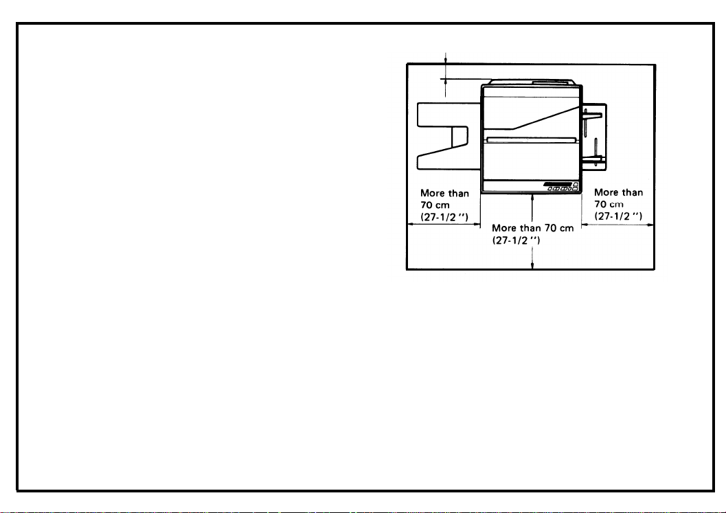
1-2. Minimum Space Requirements
1. Front :70 cm (27-1/2")
2. Back :12 cm (4-3/4")
3. Right :70 cm (27-1/2")
4. Left :70 cm (27-1 /2")
1-3. Power Source
1. Input voltage level
110V/60Hz : More than 12A
115V/60Hz : More than 12A
220V/50Hz : More than 6A
240V/50Hz : More than 6A
2. Permissible voltage fluctuation: ±10%
More than 12 cm (4-3/4")
3. Permissible extension cord:
At least 300V, 30A capacity and less than 5m
(16.4") long.
Note:
1. Be sure to ground the machine.
(Do not connect the grounding wire to
a gas pipe.
2. Make sure the plug is firmly inserted in
the outlet.
3. Avoid multi-wiring.
4. Do not set anything on the power cord.
1-2
Page 7

SECTION 2
INSTALLATION
UNPACKING
AND
Page 8

2-1. Unpacking Procedure
1.
Take out the accessory box and the machine.
2. Remove the two cushion blocks.
3. Open the vinyl bag and take out the machine.
August 1, 1985
2-1
Page 9
August 1, 1985
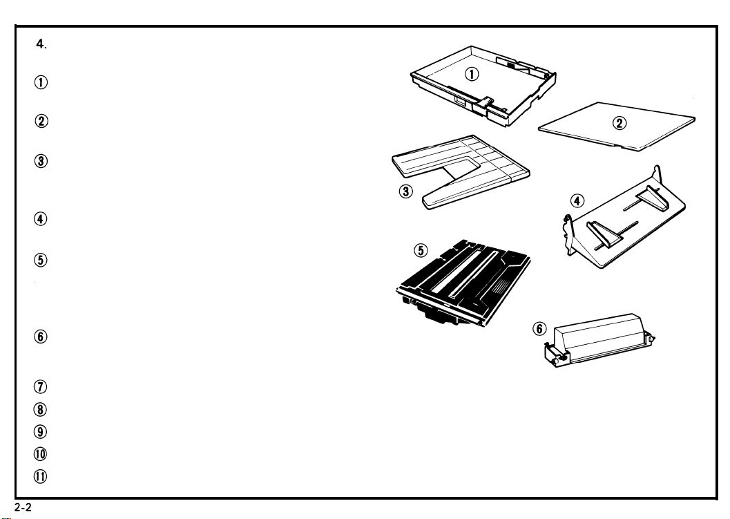
Check that the accessories are in the quantities
according to the following list.
Cassette . . . . . . . . . . . . . . . . . . . . . . . . . . . . . .
(One is in the machine.)
Cassette Cover . . . . . . . . . . . . . . . . . . . . . . . ..1 pc
Copy Tray . . . . . . . . . . . . . . . . . . . . . . . . . . . . . 1 pc
Manual Feed Guide . . . . . . . . . . . . . . . . . . . . . . 1 pc
Master Unit . . . . . . . . . . . . . . . . . . . . . . . . . . . . 1 pc
NOTE: Keep it in the box until installing it in the
copier.
2 pcs.
Toner . . . . . . . . . . . . . . . . . . . . . .
1 cartridge (Black)
●
Operating instructions . . . . . . . . . . . . . . . . . . . 1 pc
N.E.C.R . . . . . . . . . . . . . . . . . . . . . . . . . . . . . . . . . 1 pc
Envelope for N.E.C.R. (115Vonly) . . . . . . . . . 1 pc
Multi-lingualDecal(220/240Vonly) . . . . . . . 1 pc
Paper Size Decal . . . . . . . . . . . . . . . . . . . . . . . .
1 pc
Page 10
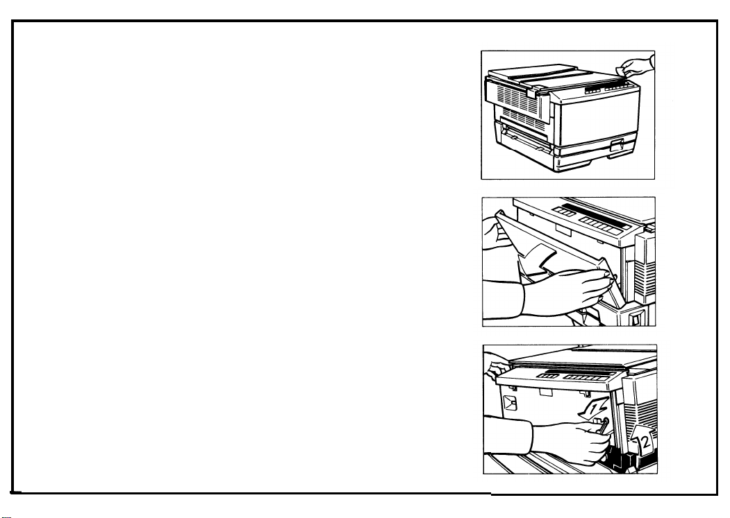
2-2. Installation Procedure
1.
Remove the two strips of tape.
2. Open the front cover.
3. Move the slider to the center and push down the
release lever to open the top unit.
2
Page 11
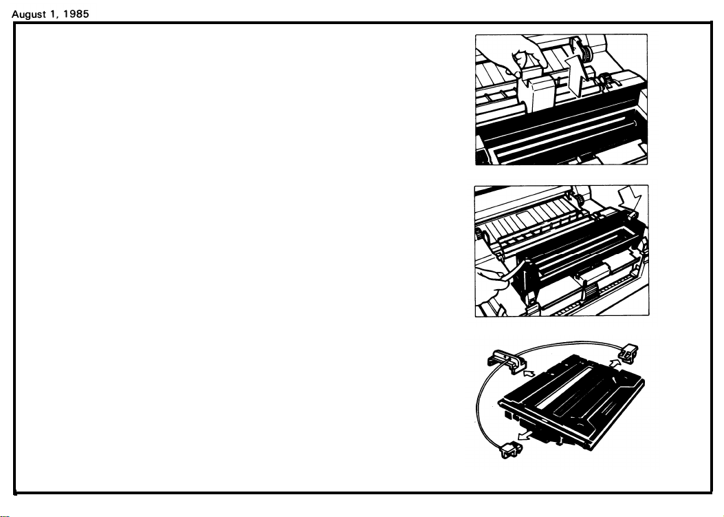
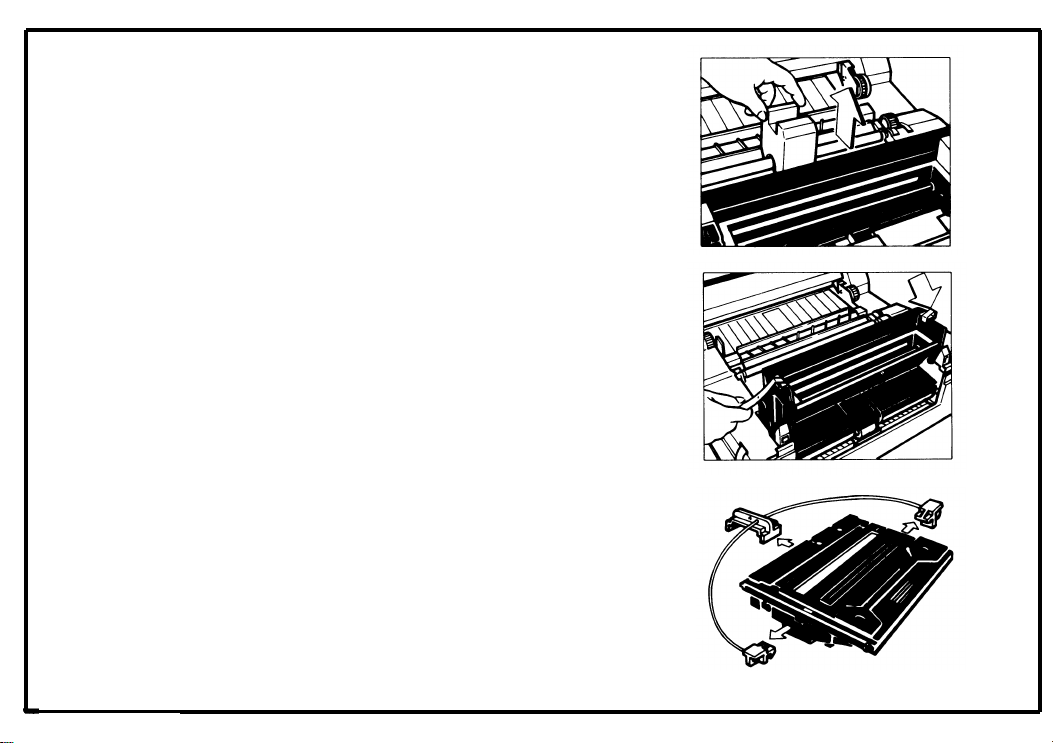
4. Remove the roller retainer.
5. Remove the two strips of tape.
6. Remove the three wedges from the new master
unit.
Note: Do not touch the master (purple material)
and avoid exposing it to light.
2-4
Page 12
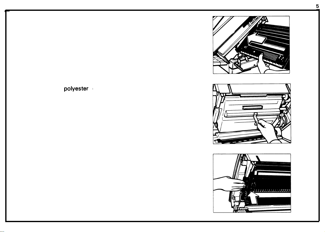
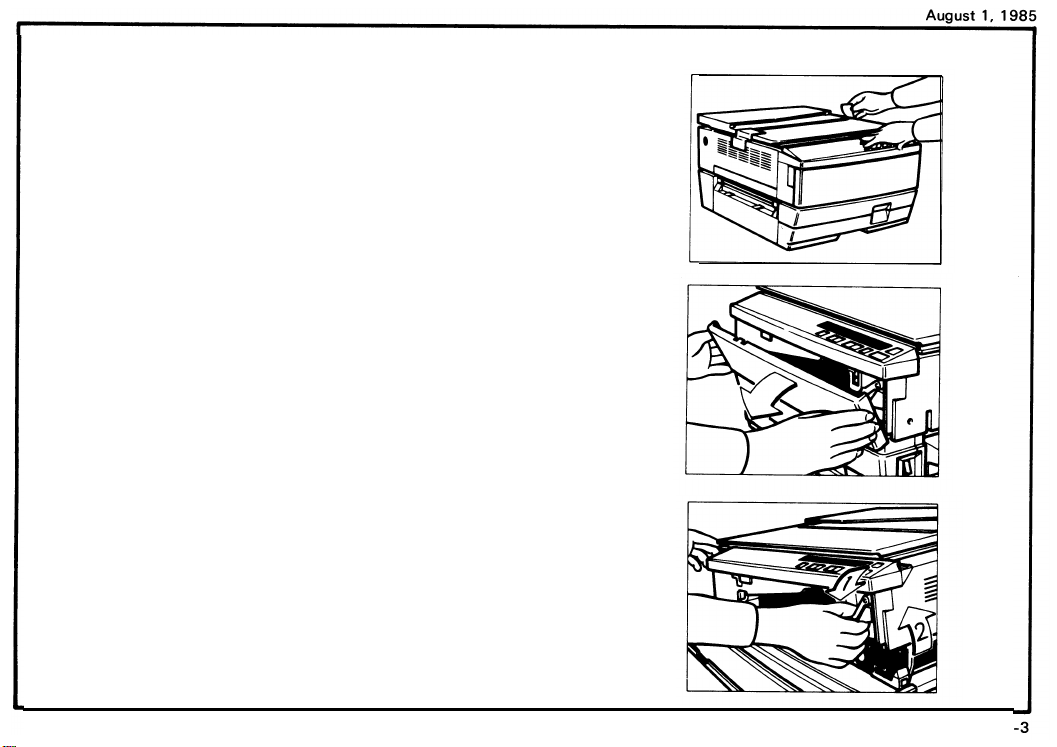
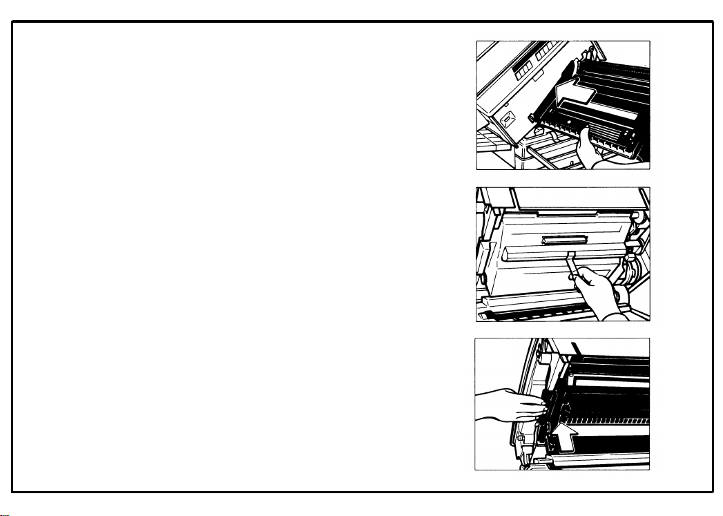
7. Insert the master unit into the copier.
August 1, 198
8. Peel off the
master.
9. Push the master unit up
cover that protects the
until it locks in place.
2-5
Page 13
August 1, 1985
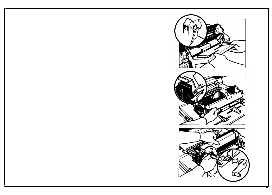
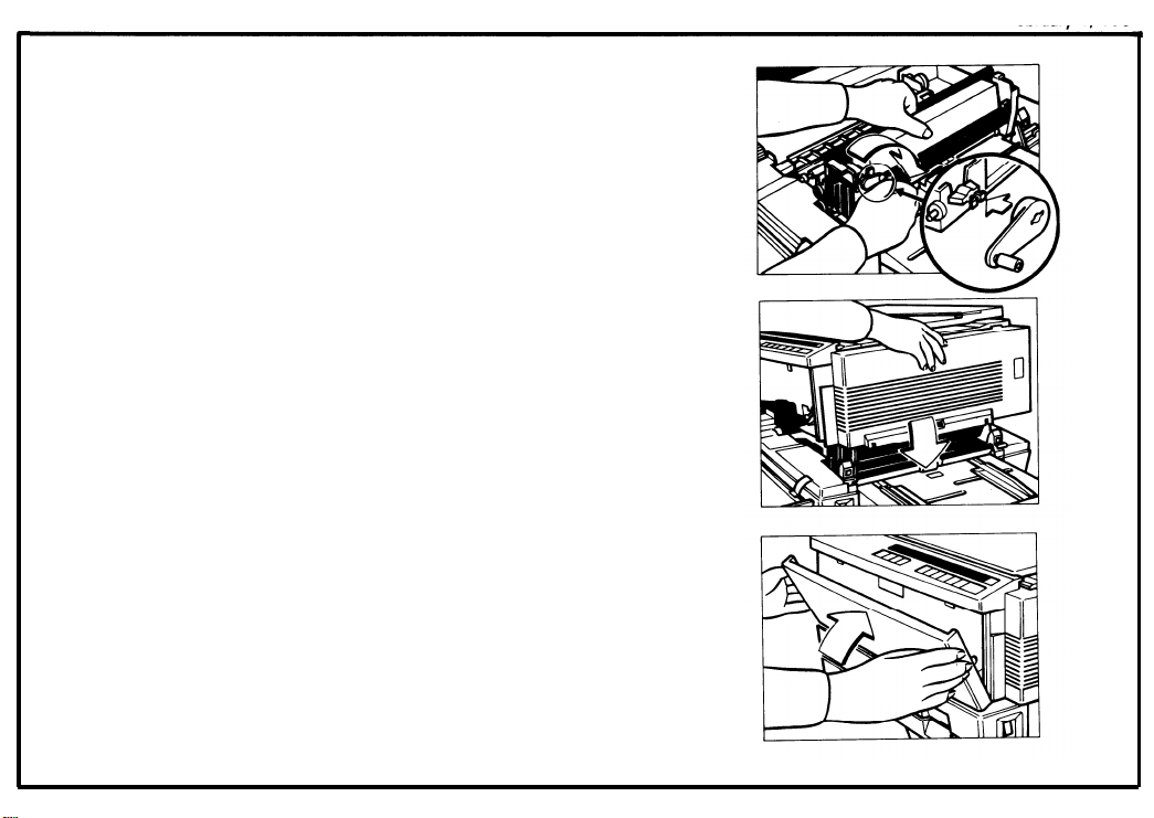
10.
Install the manual feed guide on the right side of the
machine.
11.
Shake the new cartridge of toner well.
12.
Set the pins of the toner cartridge into the slots on
the development unit.
Then, turn the cartridge
counterclockwise.
13.
Install the cartridge crank onto the shaft and turn
the cartridge crank clockwise to strip off the
cartridge seal.
Then, remove the cartridge crank and lower the top
unit.
Note: At installation, it is recommended to load
two cartridges of toner.
2-6
Page 14
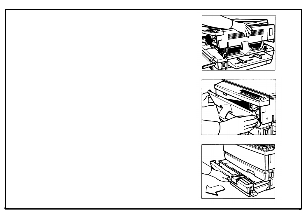
14.
Lower the top unit.
15.
Close the front cover.
16.
Pull out the cassette tray unit it stops
August 1, 1985
L
I
2-7
Page 15
August 1, 1985
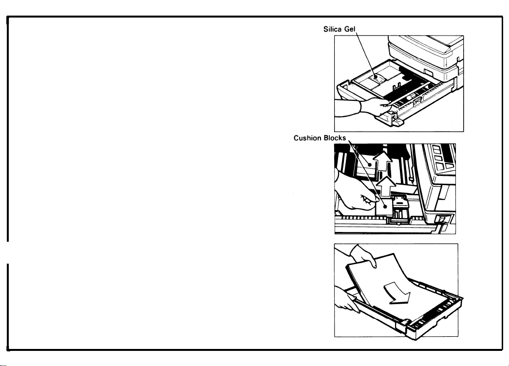
17. Remove the strip of tape and the silica gel.
18. Take out the cassette and the two cushion blocks.
I 19. Load paper into the cassette so that it is flush with
I
the front and side fences.
NOTE: The cassette holds
sheets.
approximately 250
2-8
Page 16
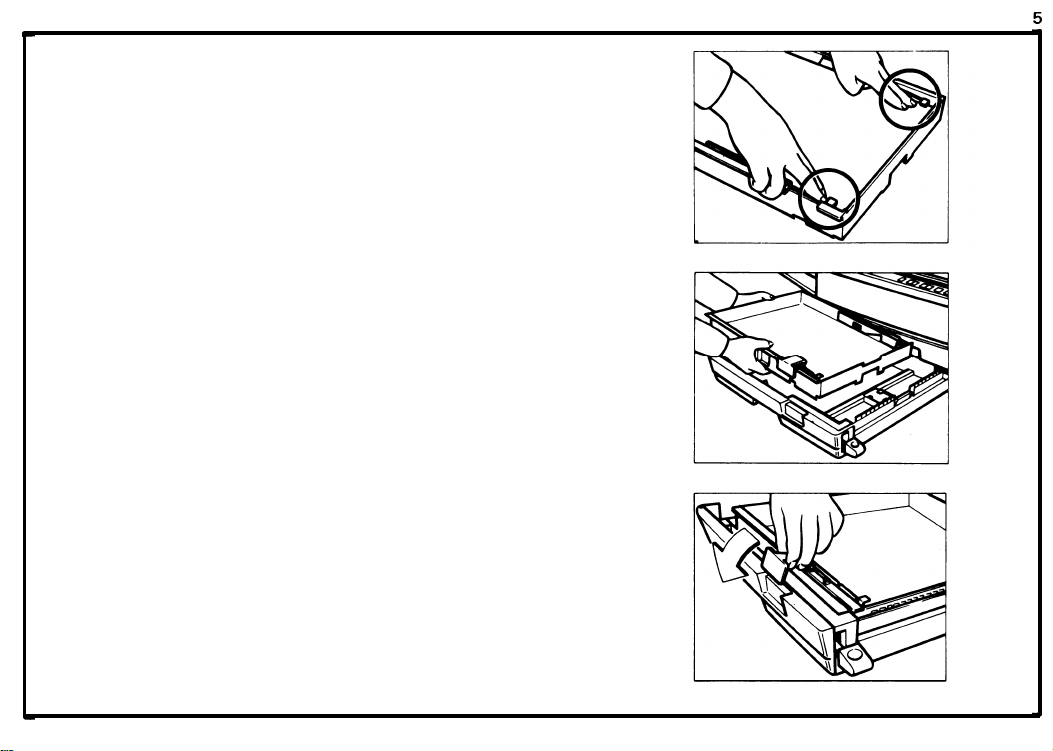
20.
Press down the corners of the paper stack so that
they catch underneath the corner separators.
21.
Set the cassette on the cassette tray.
Set the paper size flap.
22.
August 1, 198
2-9
Page 17
August 1, 1985
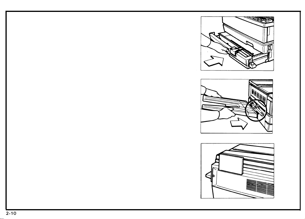
23. Push in the cassette tray until it stops.
24. Install the copy tray on the left side of the machine.
25. When not using this instruction booklet,
the holder on the back of the copier.
26. Check machine operation and copy quality.
Fill out the New Equipment Condition Report.
This completes machine installation.
place it in
Page 18
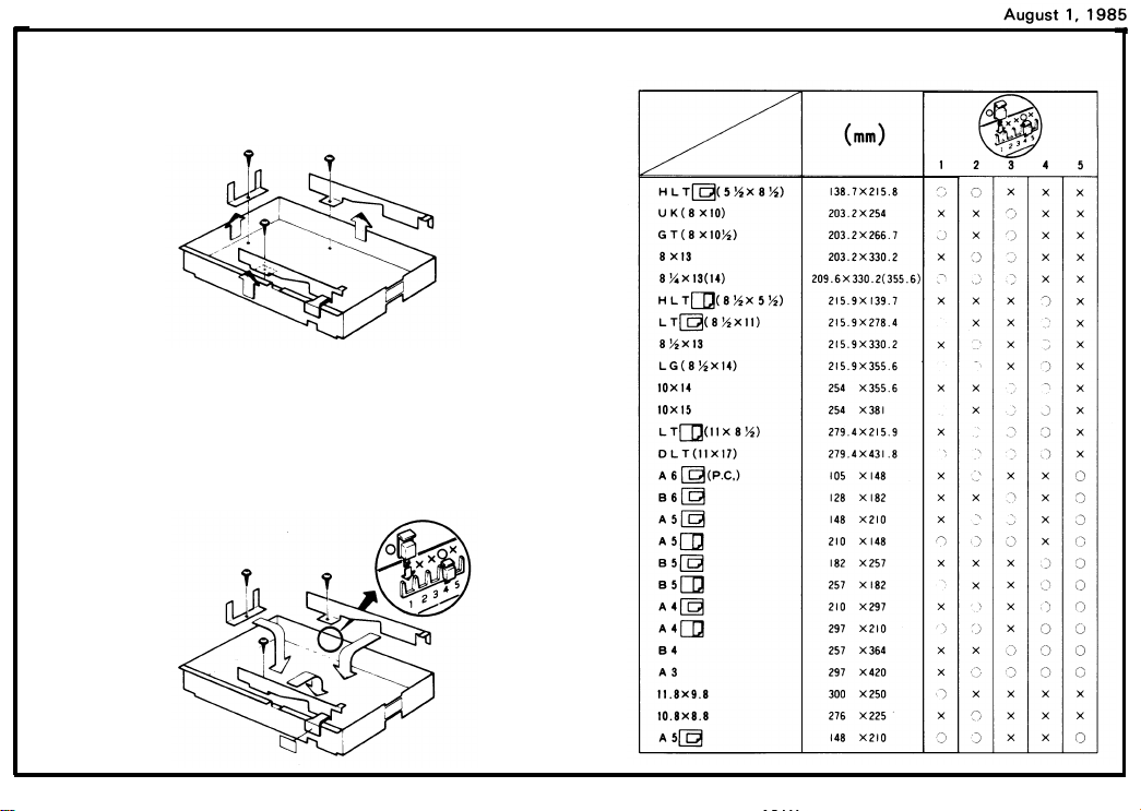
2-3. Cassette Modification
1.
Remove the side fences and the rear fence (1 screw
each).
2.
Reposition the fences to the desired paper size position.
Insert the actuators in the proper slots on the front
3.
of the cassette.
Attach the proper paper size decal on the paper size
4.
flap.
2-11
Page 19
August 1, 1985
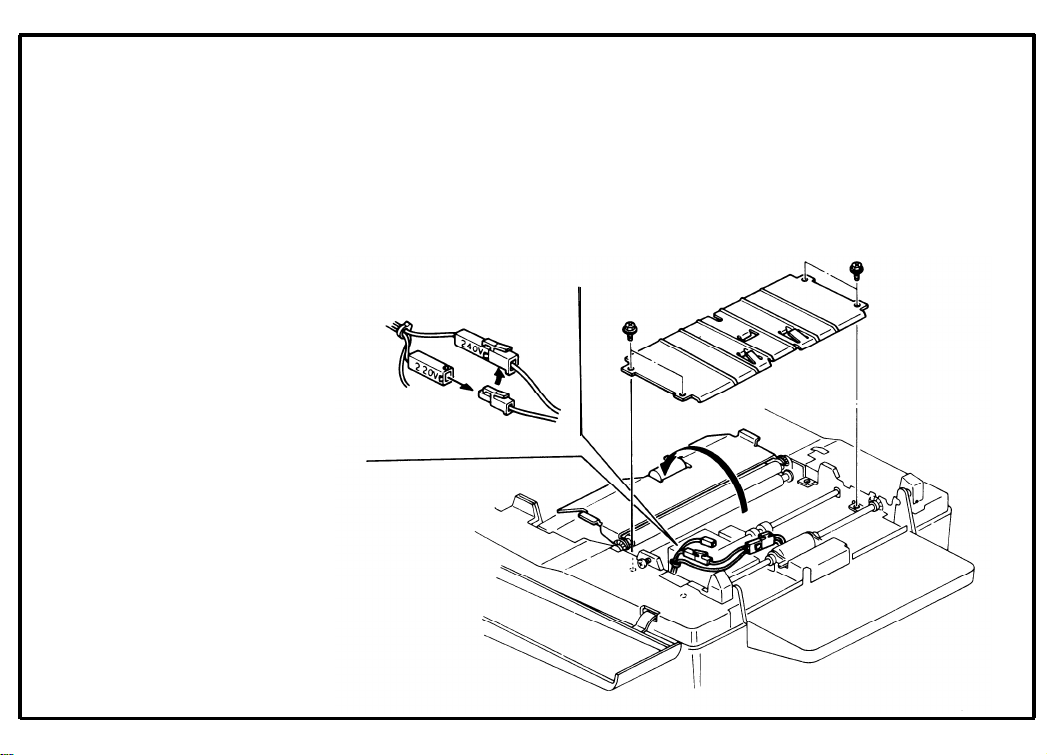
2-4. Main Transformer Conversion
(220 to 240V only)
1.
Open the top unit and remove the development unit.
2.
Swing up the upper feed guide (1 screw).
Remove the lower feed guide (4 screw).
3.
4.
Uncouple the 220V connector and couple the 240V
connector.
2-12
Page 20
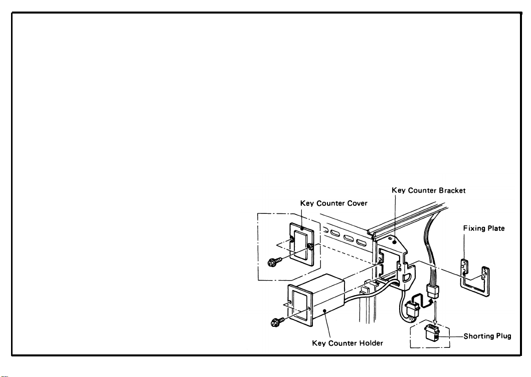
2-5.
Key Counter Holder Installation
Note: Three types of counters are recommended
for this copier (Ricoh, Hecon, and Hengstler
key counters).
Remove the upper right cover (4 screws.)
1.
Remove the key counter cover and fixing plate from
2.
the key counter bracket (2 screws).
Hold the fixing plate on the inside of the key counter
3.
bracket and insert the key holder.
August 1, 1985
2-13
Page 21

4.
Align the holes in the fixing plate with the mounting
holes of the key counter holder and secure the key
counter holder.
Note: The fixing plate has three sets of
holes. Make sure to use the holes that
match the type of counter when installing.
Remove the shorting plug from the key counter
5.
connector.
Note: This shorting plug is usually on the harness.
Plug in the key counter harness.
6.
Reassemble the copier.
7.
Insert the key counter and
check its operation.
2-14
Page 22
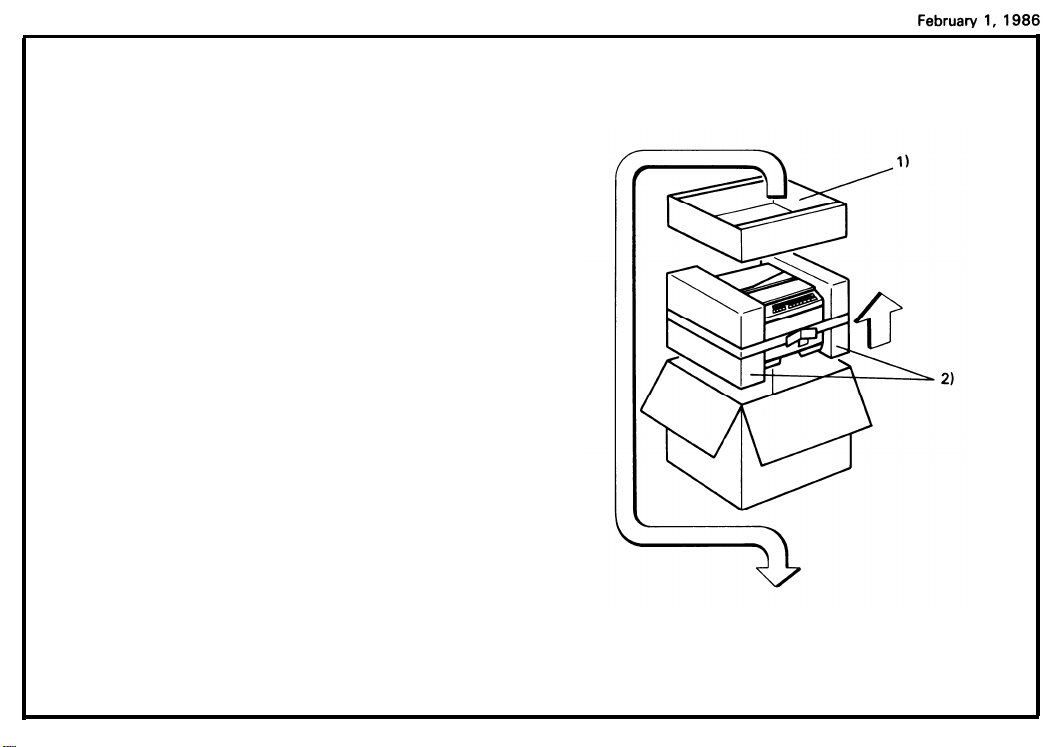
2-6. Unpacking Procedure
1. Take out the accessory box and the machine.
2. Remove the two cushion blocks.
3. Open the vinyl bag and take out the machine.
1 ) Accessory Box
2) Cushion Blocks
2-15
Page 23
February 1, 1986
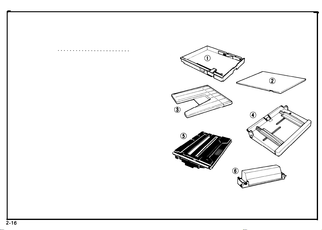
4.
Check that the accessories are in the quantities
according to the following list.
1]
Cassette . . . . . . . . . . . . . . . . . . . . . . . . . . . . . .
2)
Cassette Cover . . . . . . . . . . . . . . . . . . . . . . . . .
Copy Tray . . . . . . . . . . . . . . . . . . . . . . . . . . . . . 1 pc
3)
Paper Tray . . . . . . . . . . . . . . . . . . . . . . . . . . . . . 1 pc
4)
Master Unit . . . . . . . . . . . . . . . . . . . . . . . . . . . .
5)
NOTE: Keep it in the box until installing it in the
6)
Toner . . . . . . . . . . . . . . . . . . . . . .
7)
Operating Instructions . . . . . . . . . . . . . . . . . . . 1 pc
N.E.C.R . . . . . . . . . . . . . . . . . . . . . . . . . . . . . . . . .
8)
EnveIope for N.E.C.R. (USA only) . . . . . . . . . . 1 pc
9)
Multi-lingualDecal(220/240V only) . . . . . . . 1 pc
1
0)
11)
Paper Size Decal . . . . . . . . . . . . . . . . . . . . . . . . 1 pc
2 pcs.
3 pcs. (Asia)
(One is in the machine.)
1 pc
1 pc
copier.
1 cartridge (Black)
1 pc
Page 24
2-7. Installation Procedure
1,
Remove the two strips of tape.
2.
Open the front cover.
Move the slider to the center and push down the
3.
release lever to open the top unit.
February 1, 1986
2-17
Page 25
February 1, 1986
4. Remove the roller retainer.
5. Remove the two strips of tape.
6. Remove the three wedges from the new master
unit.
Note:
Do not touch the master (purple material)
and avoid exposing it to light.
2-18
Page 26
7. Insert the master unit into the copier,
8. Peel off the polyester cover that protects the
master.
9. Push the master unit up until it locks in place.
February 1, 1986
2-19
Page 27
February 1, 1986
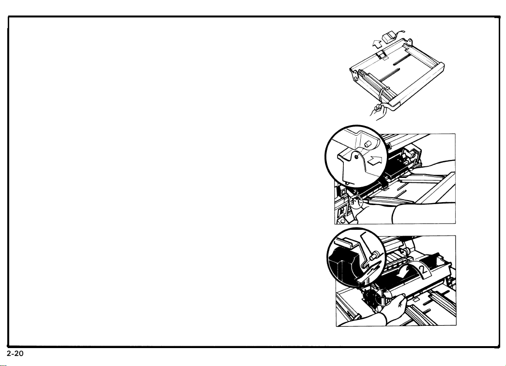
10. Remove the two strips of tape and one cushion
block from
the paper tray.
11. Install the
paper tray on the right side of the
machine.
12. Shake the new cartridge of toner well.
13. Set the pins of the toner cartridge into the slots on
the development
unit. Then, turn the cartridge
counterclockwise
Page 28
14. Install the cartridge crank onto the shaft and turn
2-21
the cartridge crank clockwise to strip off the
cartridge seal.
Then, remove the cartridge crank and lower the top
unit.
Note: At installation, it is recommended to load
two cartridges of toner.
15. Lower the top u-nit.
16. Close the front cover.
Februarv 1. 1986
Page 29
February 1, 1986
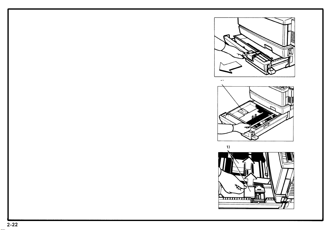
I
17. Pull out the cassette tray unit it stops.
18. Remove the strip of tape and the silica gel.
1 ) Silica Gel
19. Take out the cassette and the two cushion blocks.
1 ) Cushion Blocks
1
Page 30
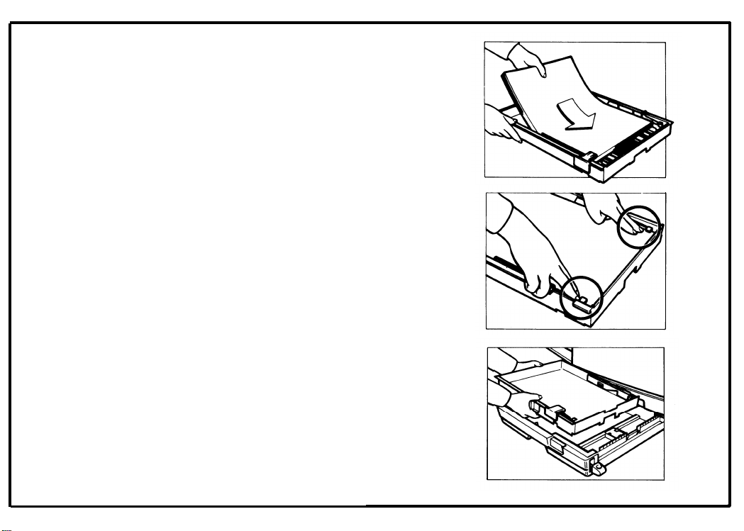
20. Load paper into the cassette so that it is flush with
the front and side fences.
Note: The cassette holds approximately 250
sheets.
Februarv 1. 1986
21. Press down the corners of the paper stack so
they catch underneath the corner separators.
22. Set the cassette on the cassette tray.
that
2-23
Page 31

February 1.1986
23. Set the paper size flap.
24. Push in the cassette tray until it stops.
25. Slide the drawer tray to the position of the paper
size.
2-24
Page 32

26.
Load paper into the paper tray.
27.
Adjust the paper guides so that they contact both
sides of the stack firmly.
28.
Install the copy tray on the left side of the machine.
2-25
Page 33

February 1, 1986
29. When not using this instruction booklet, place it in
the holder on the back of the copier.
30. Check machine operation and copy quality.
Fill out the New Equipment Condition Report.
This completes machine installation.
2-8,
Main Transformer Conversion
(220 to 240V only)
1.
Open the top unit and remove the development unit.
2.
Swing up the upper feed guide (1 screw).
Remove the lower feed guide (4 screw).
3.
4.
Uncouple the 220V connector and couple the 240V
connector.
5.
Remove the upper rear cover (2 screws).
6.
Shift the jumper wire (JP401) on the AC drive
board from T401 to T402.
Note: Slide the terminal lock up to release the jumper
wire and slide it down to secure the wire in position.
2-26
Page 34

SECTION 3
THE COPIER
PREPARATIONS
FOR TRANSPORTING
Page 35

Before moving the copier from its place of installation, be sure to prepare it for transportation as
follows. The copier may be badly damaged if it is
moved without proper preparation.
Note: * If the copier is installed with the DF or
sorter, remove them first.
(See the DF or Sorter Installation pro-
cedure.)
.
3-1. Short Distance (Room to Room)
1. Remove the copy tray and manual feed
guide/paper tray.
2. Remove the cassette tray.
3. Secure the slider with strips of tape.
CAUTION: When transporting the copier, always
use the grips on the front and rear to
handle the copier. Never grip the bottom plate of the copier.
(FT2050)
(FT2070)
February1,1986
r
3-1
Page 36

3-2. Long Distance (by vehicle)
1. Remove the copy tray and manual feed
guide/paper tray.
2. Remove the cassette tray.
3. Open the clamshell and secure the development unit with strips of tape.
4. Secure the slider with strips of tape.
CAUTION : *
3-2
While transporting the copier,
always cover the copier to avoid
direct sunshine.
*
When the copier is in a vehicle, do
not expose it to extreme hot or cold
conditions.
*
When transporting the copier,
always use the grips on the front
and rear to handle the copier.
Never grip the bottom plate of the
copier.
Page 37

SECTION 4
AND REMARKS
SERVICE TABLES
Page 38

February 1, 1986
4-1.
Maintenance Guide
Note: This guide shows the items to be cleaned and their effect on the copies if they are not clean. Clean
these items as per the maintenance table.
[ FT2050
]
4-1
Page 39

4-2
Page 40

4-2. Maintenance Table
4-3
NOTE: When you visit the customer for a service call, perform the following.
February 1, 1986
SECTION
Erase and Optics
Development
and
Quenching
ITEM TO BE CLEANED
1. Erase Lamp/Master Sensor
‘
2. Fiber Optics (FT2050)
3. Exposure Glass
4. Platen Cover Sheet
5. Exposure Lamp
6. Reflector
7. Exposure Sensor (FT2050)
8. Auto ID Sensor
9. Lens/Mirrors (FT2070)
1. Toner Metering Blade
2. Quenching Lamp
MATERIAL TO BE USED
Soft Cloth (Water) or Blower Brush
Fiber Optics/Corona Wire Cleaner
or Silicone Cloth
Soft Cloth (Glass Cleaner)
Soft Cloth (Water or Alcohol)
Wet Soft Cloth, then Dry Soft Cloth
Silicone Cloth
Blower Brush
Blower Brush
Silicone Cloth
Toner Agitator (when necessary)
Soft Cloth (Water) or Blower
Brush
Page 41

February 1, 1986
SECTION
Paper Feed
and
Transport
ITEM TO BE CLEANED
1. Paper Feed Roller
2. Friction Pad
3. 1st Relay Roller
4. 2nd Relay Roller
5. Registration Roller
6. Cassette Pad
7. Paper Guide Plates
8. Transport Belt
9. Paper Tray Pads (FT2070)
10. Pick-up Roller (FT2070)
11. Tray Feed Roller (FT2070)
Fusing
1. Hot Roller Strippers
2. Thermistor
3. Paper Guide Plates
Corona 1. Charge Corona Wire
2. Transfer Corona Wire
3. Corona Casings
4. Transfer Guide Plate
Others 1. Grid Plate of Master Unit
MATERIAL TO BE USED
Soft Cloth (Water)
Soft Cloth (Water)
Soft Cloth (Water)
Soft Cloth (Water)
Soft Cloth (Water)
Soft Cloth (Water)
Soft Cloth (Water)
Soft Cloth (Water)
Soft Cloth (Water)
Soft Cloth (Water)
Soft Cloth (Water)
Soft Cloth (Water)
Soft Cloth (Alcohol)
Soft Cloth (Water)
Fiber Optics/Corona Wire Cleaner
or Blower Brush
Cotton Swabs or Soft Cloth (Alcohol)
Soft Cloth (Water)
Soft Cloth (Water)
Blower Brush
4-4
Page 42

4-3. Lubrication Table
NOTE: Lubrication must be done within the number of copies indicated in the following table.
February 1 1986
SECTION ITEM TO BE LUBRICATED
Erase and
Optics
Paper Feed
1. Fiber Optics Holder
(FT2050)
1. Paper Feed Clutch Spring
and
Transport
2. 1st Relay Clutch Spring
3. Registration Clutch Spring
4. Tray Feed Clutch Spring
(FT2070)
5. Pick-up Clutch Spring
(FT2070)
Others 1. Master Clutch Spring
NO. OF COPIES LUBRICATING MATERIAL
As Necessary
Grease-501
60 K Mobil Temp 78
60 K Mobil Temp 78
60 K Mobil Temp 78
60 K Mobil Temp 78
60 K Mobil Temp 78
60 K
Mobil Temp 78
4-5
Page 43

4-4. Expected Life of Parts
NOTE: Main parts have the following expected service life.
4-6
SECTION
Development
Paper Feed and 1. Friction Pad
Transport 2. Tray Friction Pad
PART DESCRIPTION EXPECTED SERVICE LIFE
1. Toner Metering Blade 60 K (Black)
(FT2070)
Fusing
Corona 1. Charge Corona Wire
1. Hot Roller
2. Hot Roller Strippers
3. Pressure Roller
2. Transfer Corona Wire
6 K (Color)
60 K
60 K
120K
120K
180K
80 K
80 K
Page 44

4-5. Special Tools and Lubricants
NO. DESCRIPTION
PART NO.
August 1, 1985
REMARKS
1.
2.
3.
4.
Positioning Ring
52169003
Test Chart OS-A3 54209502
Digital Multimeter 54209507
Deluxe Test Lead
54209508
100 sheets/set
BECKMAN RMS3030
BECKMAN DL241
. Accessory Kit
5.
6.
Grease - Mobil Temp 78
Grease - Shin-etsu
54479078
52039501
400 g/can
50 g/bottle
Silicon G-501
-
/
4-7
Page 45

February 1, 1986
4-6. Points to Remember Master Unit
1.
Never touch the master belt and do not apply
oil or an organic solvent to prevent the master
belt from being deformed.
2.
When the master unit is out of the machine or
the upper clamshell is open, avoid exposing it
to a bright light or direct sun light to prevent
the master belt from being light fatigued.
3.
Always store master unit in a cool and dry
place.
4.
Do not leave master units in vehicles during
hot weather.
master units are installed in machines or
separate.
5.
The variable resistor for adjusting the master
sensor is factory preset and should not be
adjusted in the field.
6. Keep the master unit level when it is out of the
copier.
Charge
1.
The variable resistor (VR-C) is factory preset
and should not be adjusted in the field.
It does not matter whether the
2.
Do not touch the corona wire with oily hands.
Instruct the operator how and when to use the
3.
corona wire/fiber optics cleaner.
4. Clean the corona wire at every service call.
5.
Clean the grid plate with a blower brush.
Optics
1.
Clean the reflector, fiber optics/lens and mir-
rors, exposure lamp at every service call.
The variable resistor (VR - 1 ) on the exposure
2.
sensor board is factory preset and should not
be adjusted in the field
3.
The 2nd mirror positioning screws are factory
preset and should not be adjusted in the field.
(FT2070)
The exposure lamp position should be
4.
adjusted when the exposure lamp has been
removed or replaced.
5.
Check the copy image at every service call and
adjust it if necessary. (FT2070)
6.
The exposure glass has markings on every
corner of its upper surface. When replacing
the exposure glass, make sure that the markings are on the side facing upwards. (FT2070)
(FT2050).
(FT2070)
4-8
Page 46

February 1, 1986
Development
1.
When white vertical lines appear on the copy,
use the toner agitator to clean the toner
metering blade.
2.
Do not use the toner agitator unless copy
image problems occur.
damaging the toner metering blade.
3.
Be careful not to nick or scratch the develop-
ment roller surface.
4.
Be careful not to use a black development unit
for color copying, or a color development unit
for black copying.
Always store toner in a cool and dry place.
5.
Instruct the operator to ensure that the
6.
appropriate color plate is attached to all color
development units.
This is to prevent
Transfer
1.
The variable resistor (VR-T) on the transfer/
bias power pack is factory preset and should
not be adjusted in the field.
2. Do not touch the transfer corona wire with oily
hands.
Clean the transfer corona wire with a soft
3.
cloth at every service call.
Paper Feed
1.
Do not allow the paper feed rollers to become
oily or dirty.
The improper installation of paper size actua-
2.
tors causes misfeeds and erase problems.
Instruct the operator to ensure that one sheet
3.
of OHP transparency is loaded at a time and
that the OHP transparency lever is down when
copying onto transparencies (FT2070).
The improper setting of side and rear fences
4.
of the paper tray may cause erase problems
(FT2070).
4-9
Page 47

August 1, 1985
Fusing
1.
Be careful not to damage the hot roller strip-
pers.
2.
Do not touch the fusing lamp with your bare
hands.
3.
Make sure that the fusing lamp does not con-
tact the hot roller.
4.
Clean the fusing thermistor
strippers at every service call.
and hot roller
4-10
Page 48

SECTION 5
AND ADJUSTMENT
REPLACEMEMT
Page 49

5-1. Exterior Removal
FT2050
Upper
Clamshell . . . .
. . . . . . . . .
. . . .
. . . . . . . . . . .
. . . .
. . . .
.
. . . . . . . . . .
. . . . . . . . . .
5-2
FT2070
Lower
Upper
Lower
Clamshell . . . .
Clamshell . . . .
Clamshell . . . . .
.
. . . . . . . . .
. . . . . . . .
.
. . . . . . . . .
. . . .
.
. . .
. . . .
. . . . . . . . . . .
. . . . . . . . . . .
. . . . . . . . . . .
. . . .
.
. . .
.
. . .
. . . .
. . . .
. . . .
.
. . . . . . . . . .
. . . . . . . . . . .
.
. . . . . . . . . .
. . . . . . . . . .
. . . . . . . . . . 5-4-1
. . . . . . . . . .
5-3
5-4-2
5-1
Page 50

August 1, 1985
Upper Clamshell
Platen cover (2 buttons)
(1)
1.
Pull up both buttons and lift the platen
cover slightly and slide it to the rear to
remove.
Copy Tray
(2)
Upper Right Cover (4 screws)
(3)
1.
Open the clamshell slowly.
2.
Move the slider to the far left home posi-
tion by pressing the slider lock lever.
Upper Left Cover (4 screws)
(4)
1.
Open the front cover.
2.
Move the slider to the right, and loosen
the slider stopper screw.
Operation Panel (2 screws and 1 connector)
(5)
1.
Open the front cover to remove the
screws.
NO’
E: * When installing the operation panel, the
edge of the exposure glass must be in
the groove of the operation panel.
(7) Inner Cover (1 E-ring and 2 screws)
1.
Remove the operation panel.
2.
Open the clamshell and remove the
release lever.
NOTE: * When installing the inner cover, be sure
that the positioning tabs engage with the
metal frame correctly.
Slider Stopper Screw
\
Platen Cover Upper Rear Cover
#
5-2
Upper Rear Cover (2 screws)
(6)
Page 51

August 1, 1985
Lower Clamshell
(1) Front Cover (2 screws)
1.
Open the clamshell to remove the
screws.
2.
Pull out the cassette holder to remove
the front cover.
NOTE: *
(2) Manual Feed Guide
(3) Lower Right Cover (2 screws)
(4) Lower Rear Cover (4 screws)
NOTE: * Remember that one screw is longer than
When installing the front cover, be sure
that the tabs engage with the positioning
notches.
1.
Open the clamshell.
2.
Lift the manual feed guide and remove.
1.
Remove the upper rear cover (2 screws).
2.
Open the clamshell and remove.
the other three screws. The longer screw
prevents the upper paper feed guide
plate from being turned over.
(5) Lower Left Cover (2 screws)
Remove the front cover (2 screws), the
1.
upper rear cover (2 screws), and lower
rear cover (4 screws) to remove the
lower left cover.
(6) Exit Cover (2 screws)
5-3
Page 52

August 1, 1985
5-4
(7) Cassette Tray
1.
Push down the cassette release lever.
2.
Pull out the cassette tray.
3*
Lift the front of the cassette tray slightly,
and remove.
(8) Cassette Tray Cover (3 screws)
1.
Pull out the cassette tray and remove.
Page 53

February 1, 1986
Upper Clamshell (FT2070)
(1) Platen cover (2 pushlocks)
1. Pull up both pushlocks, lift the platen
cover slightly and slide it to the rear to
remove.
(2) Copy Tray
(3) Upper Right Cover (4 screws)
1. Open the front cover.
2. Move the slider to the far left.
(4) Upper Left Cover (4 screws)
1. Open the front cover.
2. Move the slider to the right.
(5) Inner Cover (1 E-ring and 2 screws)
1. Move the slider to the center and open the
clamshell.
2. Remove the release lever (1 E-ring).
NOTE: When installing the inner cover, be sure
that the positioning tabs engage with the
metal frame correctly.
(6) Operation Panel (2 screws and 1 connector)
1. Remove the inner cover (1 E-ring and 2
screws).
NOTE: When installing the operation panel, the
edge of the exposure glass must be in the
groove of the operation panel.
(7) Upper Rear Cover (2 screws)
5-4-1
Page 54

Lower Clamshell (FT2070)
(1) Front Cover (2 screws)
1. Open the clamshell to remove the screws.
2. Pull out the cassette holder to remove the
front cover.
NOTE: * When installing the front cover, make
sure that the tabs engage with the positioning notches. “
(2) Paper Tray
1. Open the clamshell.
2. Lift paper tray and remove.
(3) Lower Right Cover (2 screws)
(4) Lower Rear Cover (4 screws)
1. Remove the upper rear cover (2 screws).
2. Open the clamshell and remove,
NOTE: * Remember that one screw is longer than
the other three screws. The longer screw
prevents the upper paper feed guide
plate from being turned over.
(5) Lower Left Cover (2 screws)
1. Remove the front cover (2 screws), the
upper rear cover (2 screws), and lower
rear cover (4 screws) to remove the lower
left cover.
(6) Exit Cover (2 screws)
Longer Screw
5-4-2
Page 55

5-2. Erase and Optics FT2050
Erase Lamp Replacement . . . . . . . . . . . . . . . . . . . . . . . . . . . . . . . . . . . . . . . . . . . . . . . . . . . . . . . . . . 5-6
Slider Removal . . . . . . . . . . . . . . . . . . . . . . . . . . . . . . . . . . . . . . . . . . . . . . . . . . . . . . . . . . . . . . . . ...5-7
Slider Drive Wire Replacement . . . . . . . . . . . . . . . . . . . . . . . . . . . . . . . . . . . . . . . . . . . . . . . . . . ...5-8
Fiber Optics Removal . . . . . . . . . . . . . . . . . . . . . . . . . . . . . . . . . . . . . . . . . . . . . . . . . . . . . . . . . . . . . 5-9
Exposure Lamp Unit Replacement . . . . . . . . . . . . . . . . . . . . . . . . . . . . . . . . . . . . . . . . . . . . . . . ...5-10
.
Slider Clutch Removal . . . . . . . . . . . . . . . . . . . . . . . . . . . . . . . . . . . . . . . . . . . . . . . . . . . . . . . . . . ...5-11
Fiber Optics Holder Lubrication . . . . . . . . . . . . . . . . . . . . . . . . . . . . . . . . . . . . . . . . . . . . . . . . . . . . .5-12
FT2070
Erase Lamp Replacement . . . . . . . . . . . . . . . . . . . . . . . . . . . . . . . . . . . . . . . . . . . . . . . . . . . . . . . . . . 5-12-1
Exposure Lamp Replacement. . . . . . . . . . . . . . . . . . . . . . . . . . . . . . . . . . . . . . . . . . . . . . . . . . . . . . . 5-12-2
Exposure Lamp Positioning . . . . . . . . . . . . . . . . . . . . . . . . . . . . . . . . . . . . . . . . . . . . . . . . . . . . . . .. 5-12-3
Slider Removal . . . . . . . . . . . . . . . . . . . . . . . . . . . . . . . . . . . . . . . . . . . . . . . . . . . . . . . . . . . . . . . . ...5-12-4
Slider Drive Wire Replacement . . . . . . . . . . . . . . . . . . . . . . . . . . . . . . . . . . . . . . . . . . . . . . . . . . ...5-12-5
Lens Drive Wire Replacement . . . . . . . . . . . . . . . . . . . . . . . . . . . . . . . . . . . . . . . . . . . . . . . . . . . . . . 5-12-7
Lens Drive Motor Replacement . . . . . . . . . . . . . . . . . . . . . . . . . . . . . . . . . . . . . . . . . . . . . . . . . . ...5-12-9
Home Position Sensor Replacement . . . . . . . . . . . . . . . . . . . . . . . . . . . . . . . . . . . . . . . . . . . . . . ...5-12-10
Page 56

August 1, 1985
Erase Lamp Replacement
1.
Open the clamshell and remove the upper
right cover.
2.
Pull the master release hook and remove the
master unit.
CAUTION: * Do not touch the master belt (purple
material), and avoid exposing it to
light.
NOTE: * When installing the master unit,
sure that the master rides in the
rails.
Remove one screw and one connector.
3.
4.
Slide the erase lamp unit to the rear and
remove by turning its front end counterclockwise.
5-6
make
guide
Page 57

August 1, 1985
Slider Removal
1.
Remove the platen cover.
2.
Remove the upper rear cover,
3.
Remove the harness from the 2 clamps.
4. Remove the drive wire bracket (1 screw and 1
connector) together with the slider lock lever,
slider release lever, and slider lock spring.
5.
Remove the slider drive wire together with the
slider drive pulley (1 wire spring).
NOTE: * Position the slider lock notch just above
the slider drive pulley so that the slider
drive pulley can be removed.
6.
Remove the slider stopper, move the slider to
the left, and then remove.
NOTE: * For re-installation, see “Slider Drive Wire
Replacement” section.
* Be careful not to damage the actuator of
the home position switch when reinstalling the slider.
I
5-7
Page 58

August 1, 1985
Slider Drive Wire Replacement
1.
Remove the slider drive wire.
(See step 1 to
5 of “Slider Removal” section.)
2.
Position the slider lock notch just above the
slider drive pulley.
3.
Thread the bead on the drive wire into the
round hole on the right side of the slider.
.
4. Wind the drive wire around the slider drive
pulley three times as shown to the right.
Re-install the slider drive pulley,
5.
NOTE: * Make sure the slider drive pulley engages
properly.
Thread the eye of the drive wire into the slot
6.
on the left side of the slider.
7.
Attach the end of the wire spring onto the eye
and the another end onto the spring anchor.
Re-install the drive wire bracket, slider lock
8.
lever, slider release Iever, harness and slider
rock
spring 1 stud screw and 1 connector
NOTE: *
When re-installing the slider, the front
end of the slider must be in the groove of
the operation panel, and rest on the fiber
optics holder.
NOTE: * Make sure that the slider moves smooth-
ly and that the wire does not double over.
5-8
Page 59

Fiber Optics Removal
1.
Remove the slider.
(See “Slider Removal”
section.)
2.
Remove the upper right cover (4 screws).
3.
Close the clamshell.
Remove the reflector (2 screws).
4.
Remove the two leaf springs (1 screw each).
5.
August 1, 1985
Loosen the exposure
6.
sensor bracket (2
screws).
Pull out the fiber optics,
7.
NOTE: **Do not touch the upper and lower sur-
faces of the fiber optics.
Fiber optics must contact the fiber optics
holders.
Page 60

August 1, 1985
Exposure Lamp Unit Replacement
1.
Remove the slider.
(See “Slider Removal”
section.)
2.
Remove the operation panel (2 screws and 1
connector).
3.
Remove the upper left cover and upper right
cover.
4.
Close the clamshell.
5.
Remove the exposure lamp unit together with
.
exposure lamp bracket (1 screw, 1 washer
and 3 connectors).
6.
Remove the exposure lamp unit from the
exposure lamp bracket (1 screw).
NOTE: * Avoid touching the aperture of the
exposure lamp.
* When re-installing the exposure lamp
unit, make sure the aperture is facing up.
Exposure Lamp Unit
\
Relay Board
I
5-1o
Page 61

Slider Clutch Removal
1.
Remove the upper rear cover.
2.
Remove the drive wire bracket. (See “Slider
Removal” section.)
3.
Remove the timing belt and the master/
development drive pulley (1 E-ring).
4. Remove the slider clutch bracket (3 screws).
5.
Remove the slider drive gear and the slider
reverse gear (1 E-ring and 1 spacer each), then
remove the forward and the reverse clutch.
Slider Lock Lever
Spring
5-11
Page 62

August 1, 1985
Fiber Optics Holder Lubrication
1.
Remove the slider.
(See “Slider Removal”
section.)
2.
Apply Grease 501 to the top of the fiber
optics holders.
I
Page 63

Erase Lamp Replacement (FT2070)
1.
Unplug the copier.
2.
Remove the upper right cover and upper rear
cover.
3.
Remove the ac drive board (2 screws).
4.
Uncouple the 8 pin connector behind the ac
drive board.
5.
Open the clamshell while pressing down the
release lock.
CAUTION: * Be careful not to damage the slider.
6.
Pull the master release lever and remove the
master unit.
CAUTION: * Do not touch the master belt (purple
material), and avoid exposing it to
light.
NOTE: * When installing the master unit, make
sure that the master rides in the guide
rails.
February 1, 1986
7.
Remove the erase lamp unit by sliding it to the
rear and then to the left (1 screw).
5-12-1
Page 64

February 1, 1986
Exposure Lamp Replacement (FT2070)
1.
Remove the platen cover and slider cover (5
screws).
2.
Remove the upper right cover and the upper
rear cover.
Remove the slider stopper (1 screw).
3.
4.
Move the slider to the
-
far left, past the home
position sensor.
5.
Remove the exposure lamp cover (2 screws).
Rotate the lamp terminal as shown, and take
6.
out the lamp.
CAUTION: * Do not handle the exposure lamp
with your bare hands.
of paper. Oil from your fingers will
result in lamp discoloration.
7.
Install a new exposure lamp.
8.
Check the lamp position and the light intensity. (See “Exposure Lamp Positioning” and
“Light Intensity Adjustment” sections.)
5-12-2
Use a strip
/
8
Page 65

February 1. 1986
Exposure Lamp Positioning (FT2070)
1.
Remove the upper right cover and the upper
rear cover.
2.
Remove the slider stopper (1 screw).
3.
Move the slider to the far left, past the home
position sensor.
(See "Exposure Lamp Rep- 9.
lacement" section.)
– Horizontal Positioning —
4.
Slide the front and rear adjusting plates out of
the way so that the sight holes can be seen (1
screw each).
5.
View the lamp filament through the sight
holes on the top of the exposure lamp cover.
The filament should be directly beneath the
sight holes.
6.
To correct the position of the filament, turn
the adjusting screws.
– Vertical Adjustment –
7.
View the lamp filament from the right through
the sight holes. The filament should be the
level with the sight holes on the side of the
reflector.
8.
To correct the position of the filament, turn
the adjusting knobs until the correct position is
achieved.
NOTE: * Be sure to tighten the lock screw after
adjusting the lamp position.
■
m
Check for uneven exposure and light intensity.
(See “Uneven Image Density Adjustment”
and “Light Intensity Adjustment” sections.)
Adjusting Plate
Exposure Lamp Cover
\
\
5-12-3
Page 66

February 1, 1986
Slider Removal (FT2070)
1.
Remove the platen cover and upper rear cover.
2.
Remove the slider cover (5 screws).
3.
Remove the ac drive board (2 screws).
NOTE: * It is not necessary to disconnect the con-
nectors.
4.
Remove the slider lock spring.
5.
Remove the slider home position sensor
assembly (2 screws).
Remove the slider lock Iever and bracket.
6.
7.
Remove the slider wire tension spring.
8.
Remove the slider drive wire.
Remove the slider by moving it to the far left.
9.
NOTE: *
For reinstallation, see “Slider Drive Wire
Replacement” section.
*
The exposure glass has markings on
its
every corner
of
face. When replacing the exposure
glass, make sure that the markings are
on the side facing upwards.
I
upper sur-
5-12-4
Page 67

Slider Drive Wire Replacement (FT2070)
1.
Remove the slider drive wire.
(See “Slider
Removal” section.)
– Installation –
2.
Insert one drive wire bead in the notch at the
far right of the slider.
3.
Draw the wire” over the slider pulley (inside
track) and under the slider drive tension pulley.
4. Wind the drive wire around the slider drive
pulley (five and a half turns) and around the
slider pulley (half a turn).
5.
Insert the other drive wire bead in the notch at
the far left of the slider and connect the slider
drive tension spring.
NOTE: * Make sure that the slider moves smooth-
ly and that the wire does not double
over.
February 1, 1986
5-12-5
Page 68

February 1, 1986
6.
Seat the slider lock wire bead in its notch as
shown to the right.
7.
Reinstall the slider lock lever and bracket after
seating the bead of the slider lock wire.
Reinstall the home position sensor assembly
8.
(2 screws) and the slider lock spring.
Reinstall the ac drive board (2 screws).
9.
.
Slider Lock Wire
5-12-6
Page 69

Lens Drive Wire Replacement (FT2070)
1.
Remove the upper right cover
2.
Remove the slider. (See “Slider Removal” section.)
Remove the Auto ID sensor board from the
3.
exposure lamp assembly (2 screws and 1 harness clamp). .
4.
Remove the exposure lamp assembly (2
screws and 1 connector).
Remove the 3rd mirror cover (2 screws).
5.
Remove the lens home position sensor
6.
together with the bracket (1 screw).
Remove the 3rd mirror tension spring and
7.
slide the 3rd mirror assembly away from the
lens drive pulley.
8.
Remove the tension pulley stopper (1 screw).
February 1, 1986
9.
Slide the lens drive tension pulley towards the
lens drive pulley, and remove the lens drive
wire.
5-12-7
Page 70

February 1, 1986
– Installation –
9.
Place the short end bead of the new wire in
the right slot of the lens housing assembly.
10.
Loop the drive wire one and half turns around
the lens drive pulley. Position the center
bead in the cutout of the lens drive pulley.
11.
Run the drive wire around the lens drive tension pulley.
12.
Hook the long end bead in the left slot of the
lens housing.
13.
Reinstall the tension pulley stopper (1
screw). The gap between the lens drive tension pulley and the tension pulley stopper
should be 0.3 ± 0.2 mm.
14.
Reassemble.
5-12-8
Page 71

Lens Drive Motor Replacement (FT2070)
1.
Remove the inner cover.
2.
Remove the main board (3 screws).
3.
Uncouple the 6 pin connector behind the main
board and remove the lens drive motor harness from the wire clamp.
4.
Remove the lens drive wire.
(See “Lens Drive
Wire Replacement” section.)
Remove the lens drive motor assembly (2
5.
screws).
6.
Remove the lens drive motor unit from the
assembly (2 screws).
7.
Separate the lens drive motor from the output
gear (1 allen set screw).
February 1, 1986
5-12-9
Page 72

February 1, 1986
Home Position Sensor Replacement (FT2070)
1.
Remove the upper rear cover.
2.
Remove the ac drive board (2
3.
Remove the home
with the bracket (2
4.
Remove the home
position sensor together
screws).
position sensor from the
screws).
bracket (1 connector).
5-12-10
Page 73

5-3. Development and Quenching
Toner Metering Blade Replacement . . . . . . . . . . . . . . . . . . . . . . . . . . . . . . . . . . . . . . . . . . . . . . . . . ...5-14
Quenching Lamp Replacement (FT2050) . . . . . . . . . . . . . . . . . . . . . . . . . . . . . . . . . . . . . . . . . . . . ...5-15
Quenching Lamp Replacement (FT2070) . . . . . . . . . . . . . . . . . . . . . . . . . . . . . . . . . . . . . . . . . . . . ...5-16
February 1, 1986
5-13
Page 74

August 1, 1985
Toner Metering Blade Replacement
1.
Open the clamshell and remove the development unit.
2.
Remove the toner cartridge.
3.
Remove the front cover of the
development
unit (2 screws).
4.
Remove the roller cover bracket (1 screw), and
take off the development roller cover.
5.
Remove the toner metering blade (2 screws).
NOTE: * Avoid damaging or bending the metering
blade.
* Do not touch the surface of the develop-
ment roller.
Roller Cover Bracket
/
5-14
Page 75

Quenching Lamp Replacement
1.
Remove the upper left cover.
August 1, 1985
2.
Remove the quenching lamp
connector).
(1 screw and 1
5-15
Page 76

February 1, 1986
5-16
Quenching Lamp Replacement (FT2070)
1.
Unplug the copier.
2.
Remove the upper rear cover.
Remove the ac drive board (2 screws).
3.
4.
Uncouple the 2 pin connector behind the ac
drive board.
5.
Remove the toner overflow sensor assemb-
ly. (See “Toner Overflow Sensor Replacement.”)
6.
Remove the charge varistor (1 screw).
7.
Remove the quenching lamp by sliding the
quenching lamp unit in the direction of the
arrows and lifting it out.
NOTE: *
When reassembling, make sure that the
quenching lamp unit is seated correctly.
Page 77

5-4. Paper Feed and Transport
Paper Feed Roller Replacement . . . . . . . . . . . . . . . . . . . . . . . . . . . . . . . . . . . . . . . . . . . . . . . . . . ...5-18
Friction Pad Replacement . . . . . . . . . . . . . . . . . . . . . . . . . . . . . . . . . . . . . . . . . . . . . . . . . . . . . . . . . . 5-19
Paper Feed Clutch Lubrication . . . . . . . . . . . . . . . . . . . . . . . . . . . . . . . . . . . . . . . . . . . . . . . . . . . . ..5-20
Registration Clutch Lubrication . . . . . . . . . . . . . . . . . . . . . . . . . . . . . . . . . . . . . . . . . . . . . . . . . . . . .5-21
Paper Size Switch Replacement . . . . . . . . . . . . . . . . . . . . . . . . . . . . . . . . . . . . . . . . . . . . . . . . . ...5-22
Paper Feed Sensor Replacement . . . . . . . . . . . . . . . . . . . . . . . . . . . . . . . . . . . . . . . . . . . . . . . . . ...5-23
Transport Belt Replacement.. . . . . . . . . . . . . . . . . . . . . . . . . . . . . . . . . . . . . . . . . . . . . . . . . . . . . . . 5-24
Paper End Sensor Replacement (FT2070) . . . . . . . . . . . . . . . . . . . . . . . . . . . . . . . . . . . . . . . . ...5-24-1
Pick-up Roller Replacement (FT2070) . . . . . . . . . . . . . . . . . . . . . . . . . . . . . . . . . . . . . . . . . . . . ...5-24-2
Tray Feed Roller Replacement (FT2070) . . . . . . . . . . . . . . . . . . . . . . . . . . . . . . . . . . . . . . . . . . ...5-24-3
Pick-up and Tray Feed Clutches Lubrication (FT2070) . . . . . . . . . . . . . . . . . . . . . . . . . . . . . . . . . 5-24-5
Paper Width Sensor Replacement (FT2070) . . . . . . . . . . . . . . . . . . . . . . . . . . . . . . . . . . . . . . ...5-24-6
Paper Length Sensor Replacement (FT2070) . . . . . . . . . . . . . . . . . . . . . . . . . . . . . . . . . . . . . . ...5-24-7
5-17
Page 78

August 1, 1985
5-18
Paper Feed Roller Replacement
1.
Pull out the cassette tray from the copier.
2.
Open the clamshell and remove the manual
feed guide.
4. Remove the paper feed roller (1 snap ring).
.
NOTE: * Be careful not to touch the paper feed
roller with oily hands.
Page 79

Friction Pad Replacement
1.
Pull out the cassette tray from the copier.
2.
Peal off the friction pad from the friction pad
holder.
Install new friction pad.
3.
NOTE: * Be careful not to touch the friction pad
with oily hands.
August 1, 1985
5-19
Page 80

August 1, 1985
Paper Feed Clutch Lubrication
1.
Open the clamshell and remove the lower rear
cover.
2.
Remove the paper feed clutch bracket (2
screws, 2 E-rings, and 2 bushings).
Remove the paper feed roller gear, clutch
3.
sleeve, and clutch spring.
4. Apply Mobil Temp 78 to the clutch spring and
output hub.
NOTE: * The teeth of the clutches have one
direction. Be careful not to install them
incorrectly.
5-20
Page 81

Registration Clutch Lubrication
1.
Remove the upper rear cover and the lower
rear cover.
2.
Remove the registration clutch bracket (2
screws, 1 E-ring and 1 bushing).
Pull the engage gear bracket and move it to
3.
the upper right.
4.
Remove the output hub, clutch sleeve, clutch
.
spring and the input hub (1 allen set screw).
Apply Mobil Temp 78 to the clutch.
5.
Re-install the clutch so that the radial end of
6.
the spring and the gear side of the clutch
sleeve are facing the registration roller.
Position a 0.2mm thick gauge between the
7.
shaft shoulder and the idle gear.
Push the registration clutch towards the
8.
August 1, 1985
Page 82

August 1, 1985
Paper Size Switch Replacement
1.
Pull out the cassette tray.
2.
Remove the lower rear cover.
Remove the paper size switch together with
3.
the bracket (3 screws).
4. Remove the paper size switch from the
bracket (2 screws and 1 connector).
NOTE: * When installing the paper size switch in
the bracket, be sure that the connector
faces to the upper right hand side, as
shown in the figure.
5-22
Page 83

Paper Feed Sensor Replacement
1.
Open the clamshell.
Remove the development unit.
2.
Loosen the screw securing the lower rear
3.
cover.
August 1, 1985
4. Swing up the upper paper feed guide plate.
Remove the lower feed guide (4 screws).
5.
Remove the paper feed sensor (1 screw and 1
6.
.
connector).
NOTE: *
When closing the clamshell, be sure to
return the upper paper feed guide plate
to its original position. Otherwise, the
master will be damaged.
*
Do not forget to tighten the screw securing the lower rear cover.
Page 84

August 1, 1985
Transport Belt Replacement
1.
Remove the copy tray.
2. Remove the front cover (2 screws), upper rear
cover (2 screws), and lower rear cover (4
screws).
3. Remove the 2 clamshell stopper screws and
stand the clamshell straight up.
NOTE: * When standing the clamshell straight up,
place a block that has a height of
approximately 80 mm (approx. 3") in
front of exit cover as shown to the upper
right.
4. Remove the transport guide plate (2 screws).
5. Remove the safety cover (1 screw).
6. Remove the transport belt gear bracket (2
screws).
7. Remove the idle gear (1 E-ring).
8. Remove the paper reverse gear (1 E-ring and
bushing).
9. Remove the first transport pulley from the
transport belt holder.
NOTE: * When reassembling, make sure that the
1st transport pulley rides in the small
grooves of the transport belt holder.
10. Remove the transport belt from the holder.
5-24
Page 85

Paper End Sensor Replacement (FT2070)
1.
Remove the paper tray.
2.
Remove the paper turn guide by sliding it to
the rear and pulling its front to the right (2
screws).
Remove the paper end sensor unit (1 screw
3.
and 1 connector).
4.
Remove the paper end sensor actuator by
flexing the paper end sensor bracket gently.
5.
Separate the paper end sensor from the
bracket (2 screws).
NOTE: * When reassembling, make sure that the
paper end sensor unit is seated correctly.
5-24-1
Page 86

February 1, 1986
Pick-up Roller Replacement (FT2070)
Remove the paper tray.
1.
2.
Rotate the pick-up roller shaft so that the flat
sides align with the shaft holder openings.
Pull the rear end of the roller shaft toward the
3.
right and slide it to the rear.
4. Remove the pick-up roller.
Shaft Holder Opening
5-24-2
NOTE: *
After reinstalling the pick-up roller,
rotate the roller shaft so that the flat
sides do not align with the shaft holder
openings.
Page 87

Tray Feed Roller Replacement (FT2070)
1.
Remove the front cover, paper tray, and the
lower rear cover.
Remove the development unit.
2.
Remove the tray feed solenoid (2 screws and
3.
2 harness clamps).
4.
Unhook the sector gear spring and the tray
.
feed solenoid spring.
5.
Remove the paper feed clutch bracket (3
screws, 4 E-rings, and 4 bushings).
Remove the first relay roller (2 springs and 2
6.
bushings).
7.
Remove the rear development unit supports (2
screws).
Remove the safety switch assembly (1 screw).
8.
NOTE: * It is not necessary to disconnect the
safety switch.
February 1, 1986
9. Remove the front development unit support (2
screws).
10. Take off the width sensor cover (2 screws).
5-24-3
Page 88

February 1, 1986
11.
Remove the front and rear screws securing
the feed roller housing.
12.
Remove the pick-up spring and the spring
housing.
13.
Remove the E-ring and bushing from the front
of the tray feed shaft. Slide the shaft to the
rear and lift the front of the tray feed shaft.
14.
Remove the front feed roller housing by sliding
it to the front.
15.
Remove the tray feed roller by sliding the pickup stay to the front (1 E-ring and 1 bushing).
NOTE: * As the tray feed roller has a one-way
clutch, it is important to mount the roller
correctly.
The pick-up roller drive belt
should be towards the front.
*
When replacing the paper feed clutch
bracket, secure it with the three screws,
then slide the pick-up gear slightly to the
front and align the sector gear and the
pick-up gear as shown in
figure. (The marked tooth on the sector gear fits in between the marked teeth
of the pick-up gear.)
the
5-24-4
Page 89

February 1, 1986
Pick-up and Tray Feed Clutch Lubrication NOTE: * When reinstalling the spring clutches, be
(FT2070)
sure to insert the projections of the
clutch springs into the notches.
Remove the lower rear cover.
1.
2.
Remove the tray feed solenoid (2 screws and
2 harness clamps).
3.
Unhook the sector gear spring and the tray
feed solenoid spring.
Remove the paper feed clutch bracket (3
4.
* When replacing the paper feed clutch
bracket, secure it with the three screws,
then slide the pick-up gear slightly to the
front and align the sector gear and the
pick-up gear. (The marked tooth on the
sector gear fits between the marked
teeth of the pick-up gear.)
screws, 4 E-rings and 4 bushings).
Remove the sector gear.
5.
Remove the pick-up clutch cam (1 E-ring).
6.
Remove clutch pawl assembly
7.
Remove the clutch assembly.
8.
Disassemble and lubricate the
9.
(1 E-ring).
pick-up clutch
and tray feed clutch.
CAUTION: * Be careful not to loose the clutch
drive pin.
5-24-5
Page 90

February 1, 1986
Paper Width Sensor Replacement (FT2070)
1.
Open the clamshell.
2.
Remove the development unit.
3.
Remove the width sensor cover (2 screws).
4.
Replace the paper width sensors (1 connector
each).
5-24-6
NOTE: *
When reinstalling the width sensor
cover, first insert the positioning tabs
into the positioning notches.
Page 91

Paper Length Sensor Replacement (FT2070)
1.
Remove the paper tray.
2.
Remove the paper turn guide (2 screws).
3.
Disconnect the length sensor connector.
4.
Remove the screw securing the length sensor
bracket.
.
5.
While pushing in the length sensor interrupter,
slide the length sensor bracket to the right.
6.
Replace the paper length sensor (1 screw).
February 1, 1986
Length Sensor Interrupter
5-24-7
Page 92

5-5. Image Fusing
Hot Roller Replacement . . . .
Pressure Roller Replacement
Thermistor Replacement . . .
.
. . .... . . . . . . . . . . . . . . . . . . . . . . . . . . . . . . . . . . . . . . . . . . . . . . . . . .
. . . . . . . . . . . . . . . . . . . . . . . . . . . . . . . . . . . . . . . . . . . . . . . . . . . . . . . . .
5-26
5-28
5-29
Thermofuse Replacement . . . . . . . . . . . . . . . . . . . . . . . . . . . . . . . . . . . . . . . . . . . . . . . . . . . . . . . . . ...5-30
Hot Roller Strippers Replacement . . . . . . . . . . . . . . . . . . . . . . . . . . . . . . . . . . . . . . . . . . . . . . . . . . ...5-31
Exit Sensor Replacement . . . . . . . . . . . . . . . . . . . . . . . . . . . . . . . . . . . . . . . . . . . . . . . . . . . . . . . . . ...5-32
5-25
Page 93

August 1, 1985
Hot Roller Replacement
Open the exit assembly. (See “Hot Rollers
1.
Strippers Replacement” section.)
Open the clamshell and stand it straight
2.
up. (See “Transport Belt Replacement” section.)
Remove the fusing unit cover (2 screws).
3.
4.
Remove the fusing stay (4 screws).
Holding the front end of the fusing lamp,
5.
.
remove the front terminal bracket (1 screw).
Pull out the fusing lamp gently.
6.
Remove the rear terminal bracket (1 screw).
7.
Remove the safety cover (1 screw).
8.
Remove the front and rear pressure roller
9.
springs.
CAUTION: * Remove the springs carefully as the
springs have high tension.
5-26
Page 94

10. Remove the bearing from the front end of the
hot roller (1 C-ring).
11. Remove the gear from the rear end of the hot
roller (1 C-ring).
12. Remove the hot roller carefully.
August 1, 1985
I
NOTE: *
Be careful not to damage the hot roller.
*
When installing the fusing lamp, make
sure both “end of the fusing lamp properly contact the terminals.
*
After re-installing the pressure roller
springs,
check that the springs are
mounted into the pressure lever properly.
5-27
Page 95

August 1, 1985
Pressure Roller Replacement
1.
Remove the hot roller.
lacement” section.)
2.
Remove the transport belt gear bracket (2
screws).
Remove the 2 idle gears as shown to the right
3.
(1 E-ring each).
4.
Remove the rear hot roller bearing.
Remove the transport guide plate (2 screws).
5.
Swing the pressure roller cover away from the
6.
pressure roller (2 screws).
7.
Remove the pressure roller.
8.
Remove the front and rear bushings (1 E-ring
each).
(See “Hot Roller Rep-
.
NOTE: * Be careful
5-28
not to damage the pressure
roller.
Page 96

Thermistor Replacement
1.
Open the clamshell and stand it straight
up. (See “Transport Belt Replacement” sec-
tion.)
2.
Remove the fusing unit cover (2 screws).
Remove the fusing stay (4screws).
3.
“Hot Roller Replacement” section.)
.
August 1, 1985
(See
4.
Remove the transport guide plate.
“Transport Belt Replacement” section.)
Remove the thermistor (1 screw and 1
5.
nector).
(See
con-
5-29
Page 97

Thermofuse Replacement
1.
Open the clamshell and stand it straight
up. (See’’Transport Belt Replacement” section.)
2.
Remove the fusing unit cover (2 screws). (See
“Hot Roller Replacement” section.)
Remove the fusing stay (4 screws).
3.
Remove the transport guide plate (2 screws).
4.
(See “Transport Belt Replacement” section.)
Remove the rear fusing lamp terminal (1
5.
screw).
CAUTION: * When removing the rear fusing lamp
terminal, be careful not to damage
the fusing lamp.
6. Remove the thermofuse harness from the rear
fusing lamp terminal (1 screw).
7. Disconnect the thermofuse connector from
the fusing power supply board.
8. Remove the screw securing the front end of
the thermofuse stay.
.
9. Lift the thermofuse stay and disconnect the
thermofuse connector from the stay.
10. Remove the thermofuse.
NOTE: * When installing the thermofuse, be sure
to route the wire properly as shown in
the figure.
5-30
Page 98

Hot Roller Strippers Replacement
Open the front cover.
1.
Remove the exit cover.
2.
Open the exit assembly (2 screws)
3.
Remove the hot roller strippers together with
4.
springs.
NOTE: * It is advisable to replace the hot roller
strippers as a set.
August 1, 1985
5-31
Page 99

August 1, 1985
Exit Sensor Replacement
1.
Remove the lower left cover (2 screws).
2.
Open the front cover.
Remove the exit cover (2 screws).
3.
4.
Open the exit assembly and remove the exit
assembly (2 screws).
5.
Remove the transport guide plate (2 screws).
(See "Transport Belt Replacement" section.)
Remove the exit sensor (1 screw, 1
6.
and 2 clamps).
.
connector
Page 100

5-6. Corona
5-33
Charge Corona Wire Replacement . . . . . . . . . . . . . . . . . . . . . . . . . . . . . . . . . . . . . . . . . . . . . . . . . ...5-34
Transfer Corona Wire Replacement . . . . . . . . . . . . . . . . . . . . . . . . . . . . . . . . . . . . . . . . . . . . . . . . ...5-35
August 1, 1985
 Loading...