

Page 1

T
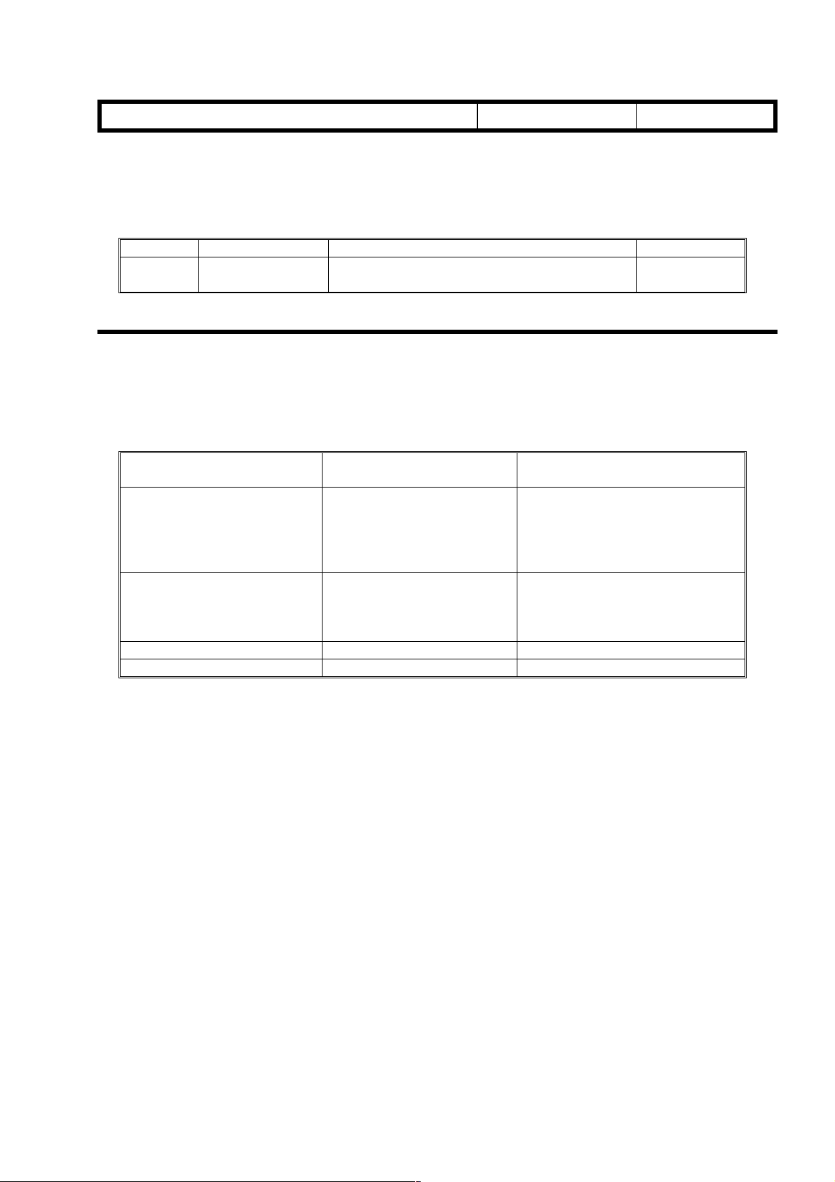
Model:
Skylark 2
echnical
B
ulletin
Date:
15-Oct-98
No:
PAGE: 1/6
1
Subject:
From:
Classification:
A new model “Skylark 2 (A270/A271)” will be launched in January 98. Skylark 2 is a
slightly modified version of the already existing model “Skylark (Ricoh FT2012/2212,
Gestetner 2812/2812z, Nashuatec 3612s/3612, Rex-Rotary 8612/8612z, Infotec
5121/5121 z)”.
There will be seven destination codes depending on the are a: -57 is Middle East / South
America (Ricoh), -27 is Europe (Ricoh), -29 is Asia and Africa (Ricoh), -23 is Russia
(Ricoh), -10 is Middle East/South America (Gestetner and Nashuatec), -22 is Europe and
Asia (Gestetner, Nashuatec and Rex-Rotary), -26 is Europe (Infotec).
This RTB clarifies the differences between the base copier and Skylark 2 (based on the
style of the service manual).
Differences from Skylark
GTS and S Field Infomation Dept.
Troubleshooting
Mechanical
Paper path
Other ( )
Part information
Electrical
Transmit/receive
Prepared by:
Action required
Service manual revision
Retrofit information
K. Miura
1. OVERALL MACHINE INFORMATION
1. SPECIFICATIONS
Copy Paper Size: A4, 8.5’’ x 11’’, 8.5’’ x 13’’, 8.5’’ x 14’’, A5, 5.5’’ x 8.5’’
Warm-up Time: Less than 15 seconds (at 23 °C)
5 stepsManual Image Density:
Selection
Power Source: 120V/60Hz:
More than 10 A (for Middle East/South America)
220~240 V/50Hz:
More than 6 A (for Europe)
230V/50Hz:
More than 6 A (for Middle East/Asia)
Power Consumption:
Maximum 0.9 kW
Copy cycle 0.5 kW
Warm-up 0.7 kW
Stand-by 0.1 kW
Page 2
T
Model:
Skylark 2
echnical
B
ulletin
Date:
15-Oct-98
No:
2. ELECTRICAL COMPONENT DESCRIPTIONS
The following transformer is not included in this copier.
Symbol Name Function Index No.
TR Transformer Steps down the wall voltage t o 30 Vac and 8
Vac.
2. DETAILED DESCRIPTIONS
1. FUSING LAMP CONTROL
To reduce warm-up time, fusing lamp control has been changed as follows:
PAGE: 2/6
1
31
Machine Condition Fusing Lamp
ON/OFF Threshold
After the main switch is
turned on, until one minute
has past after the fusing
temperature reaches
°C
.
After the above time period
During copying 185 °C
After copying is finish ed
130
185 °C After using temperature reaches
110 °C
110 °C
Remarks
130 °C
fusing lamp is kept on unt il it
reaches 185 °C.
When the Start key is pressed,
the red indicator blinks and
copying starts after the fusing
temperature reaches
(ready temperature), the
130 °C
.
Page 3

T
Model:
Skylark 2
echnical
B
ulletin
Date:
15-Oct-98
3. INSTLLATION PROCEDURE
1. COPIER ACCESSORY CHECK
1. Imaging Unit
2. Error Code Decal - English (except for -23 machines)
3. Error Code Decal - German (-26 machines)
4. Error Code Decal - French (-26 machines)
5. Error Code Decal - Italian (-26 machines)
6. Error Code Decal - Spanish (-26, -57 machines)
7. Error Code Decal - Portuguese (-57 machine s )
8. Operating Instructions - English (except for -27 machines)
9. Operating Instructions - German (-26 machines)
10. Operating Instructions - French (-26 machines)
11. Operating Instructions - Italian (-26 machines)
12. Operating Instructions - Spanish (-26, -57 machines)
13. Operating Instructions - Portuguese (-57 machines)
14. Model Name Decal (-22 machines)
15. NECR - English (-57 machines)
16. NECR - Multi-language (-23, -27, -29 machines)
17. User Survey Card (-57 machines)
18. Installation Procedure - English (except for -23 machines)
19. Installation Procedure - German (-22, -26, -27 machines)
20. Installation Procedure - French (-22, -26, -27 machines)
21. Installation Procedure - Italian (-22, -26, -27 machines)
22. Installation Procedure - Spanish (-22, -26, -27, -57 machines)
23. Installation Procedure - Portuguese (-57 machines)
24. Installation Procedure - Russian (-23 machines)
No:
PAGE: 3/6
1
2. COPIER INSTALLATION PROCEDURE
The paper cassette is not wrapped with a clear wrapper. It is initially installed in the paper
tray.
Page 4

T
Model:
Skylark 2
echnical
B
ulletin
Date:
15-Oct-98
No:
PAGE: 4/6
1
4. SERVICE TABLES
Access to and operation of SP mode has been changed for Skylark 2 due to the layout
change of the operation panel. Details of difference in the operation are listed below. The
differences are shown in bold letters.
1. SERVICE PROGRAM MODE ACCESS PROCEDURE
1. Turn off the main switch.
2. While pressing
switch.
3. A dot(•) will appear in the top left corner of the Copy Counter.
4. Release
Lighter key (if not pressed within 5 seconds, the machine will return to the copy mode).
The copier is ready to accept the program number.
the Auto Density key
the Auto Density key
and Clear/Stop key, and within 5 seconds, press the
and Clear/Stop key together, turn on the main
2. HOW TO SELECT THE PROGRAM NUMBER
1. By using the Increase or De crease Quantity (“+” or “-“) keys, enter the required
number. At this point, the Copy Counter will be blinking, and the dot (•) will be lit.
2. When the
Copy Counter will be entered as the selected program number.
Auto Density key
is pressed, the number which is currently blinking in the
3. CHANGING THE VALUE OF AN SP MODE
1. Enter the desired value or setting using the Increase or Decrease Quantity (“+” or “-“)
keys. For some modes, since the Copy Counter has only digits, the first digit is
displayed in the Manual Image Density indicator as shown below.
NOTE:
2. When
Copy Counter will be entered as the new value or setting, and will be stored in memory.
3. The copier is ready to accept the new program number. Repeat from step 1 or leave
SP mode by turning the main switch off/on.
After changing the value (setting), the previous value (setting) can be recalled
again if the Clear/Stop key is pressed at this point.
the Auto Density key
is pressed, the number which is currently displayed in the
Page 5

T
Model:
Skylark 2
echnical
4. SERVICE PROGRAM MODE TABLE
Mode No. Function Settings
14 Auto Shut Off Selects the auto shut off time. 0: 5 min.
Timing Setting The copier main switch is shut off automatically
after the selected auto shut o f f t ime if SP77 is at
This part has been
changed!
19 ADS Priority
Setting
34 Image Density
Adjustment
This part has been
changed!
“0”.
Specifies whether the cop ier de faults to APS or
manual mode when the ma in switch is turned on,
auto reset, or mode cleared.
Selects the image dens it y level in ADS and
manual ID mode.
The exposure lamp data is in creased or
decreased. This adjust ment affects ADS mode
and all manual ID settings.
SP Setting Setting Exposure lamp
0
1
2
3
4
5
6
The exposure lamp setting specifies the change
relative to the base exposure lamp voltage (Vo)
in SP48, 1 step of the lamp voltage equals 0.5 V
for 120 V, and 1.0V for 230V (EU) machines.
Normal
Light
Dark
Lighter
Darker
Lightest
Darkest
B
ulletin
Date:
15-Oct-98
0
+3 steps
-3 steps
+6 steps
-6 steps
+10 steps
-10 steps
No:
1
1: 10 min.
2: 15 min.
3: 20 min.
4: 25 min.
5: 30 min.
6: 60 min.
7: 240 min.
0: ADS
1: Manual ID
Level 3
0: Normal
1: Light
2: Dark
3: Lighter
4: Darker
5: Lightest
6: Darkest
PAGE: 5/6
For only SP34 and SP57, the copies are made
with ADS mode (ot her SP modes use man ual
ID level 3).
5. PREVENTIVE MAINTENANCE
1. SPECIAL TOOLS AND LUBRICANTS
The digital multimeter has been changed.
Part Number Description Q’ty
A0299387 Digital Multimeter 1
Page 6

T
Model:
Skylark 2
echnical
B
ulletin
Date:
15-Oct-98
No:
PAGE: 6/6
1
6. POINT-TO-POINT DIAGRAM
The AC drive / DC power supply board has been changed and the transformer has been
eliminated as shown.
T408
T407
FUSING LAMP
DRIVE CIRCUIT
TR
SWITCHING
CIRCUIT
FUSING LAMP
EXPOSURE LAMP
CN405-1
CN405-2
CN405-3
CN405-4
CN405-5
CN403-1
CN403-2
CN403-3
CN403-4
CN403-5
CN404-1
CN404-2
CN404-3
CN404-4
CN404-5
CN404-6
CN404-7
CN404-8
CN404-9
T405
T406
T404
T403
T401
T402
CN402-1
FUSE1
CN402-2
EXPOSURE LAMP
DRIVE CIRCUIT
RY1
 Loading...