

Page 1
Technical Bulletin No. RTB-001
SUBJECT: NIP BAND WIDTH AND TRAILING EDGE SKEW
ADJUSTMENT
PREPARED BY: M. Ishihara
CHECKED BY:
CLASSIFICATION:
Action Required
Troubleshooting
Retrofit Information
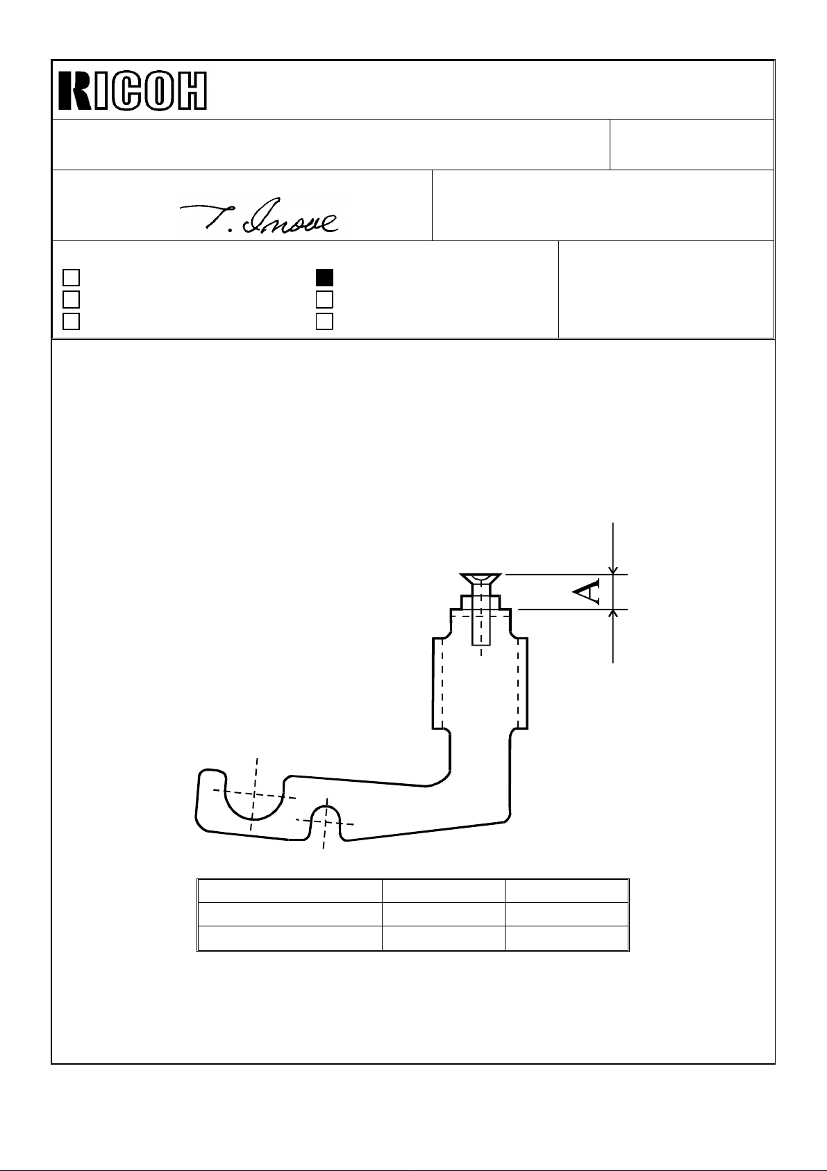
1. Nip Band Width Adjustment
The nip band width of this model is decided by the height of each screw on both fusing
unit pressure arms.
Adjust the height of the screw on each pressure arm as follows:
Revision of service manual
Information only
Other
FROM: 1st Field Information Dept. QAC
MODEL:
Skylark (A183/A184)
DATE: Oct. 31, ’96
PAGE: 1 of 2
Item Parts No. Specification
Right Pressure Arm
Left Pressure Arm
❋ Note that the adjustment specification differs between the two pressure arms.
A1844085
A1844086
8 ± 0.2
7.5 ± 0.2
Page 2
Technical Bulletin No. RTB-001
SUBJECT: NIP BAND WIDTH AND TRAILING EDGE SKEW
ADJUSTMENT
2. Trailing Edge Skew Adjustment Procedure
Perform the following procedure in the field to decrease the amount of trailing edge skew:
1) Measure the height of the screw on both fusing unit pressure arms. (The factory
standard specification is described on the previous page.)
2) Change the screw height, making sure of the following:
NOTE: • The skew will be reduced 0.1 mm by turning the screw once.
• The height of the screw will change 0.7 mm by turning once.
• Do not turn the screw more than 3 turns.
✩ If the skew on the copy paper is to the right, turn the left pressure arm screw
clockwise.
DATE: Oct. 31 ’96
PAGE: 2 of 2
✩ If the skew on the copy paper is to the left, turn the right pressure arm screw
clockwise.
Page 3

RICOH Technical Bulletin PAGE: 1/1
Model: Skylark Date: 31-Mar-97
Subject: SC Code #96 Prepared by: M.Ishihara
From: QAC 1st Field Information Dept. Checked by: T. Inoue
Classification:
The following should be added to the “SERVICE CALL CONDITIONS” in the Service
Manual.
Troubleshooting
Mechanical
Paper path
Other ( )
Part information
Electrical
Transmit/receive
Action required
Service manual revision
Retrofit information
No: 2
CODE #96 - MAIN SWITCH ERROR
Definition
The machine does not turn off within 8.5 seconds after Auto Shut Off is performed.
Possible Causes
• Defective main switch.
• Connectors of the main switch are not correctly connected.
• Defective dc harness of the main switch connection (some lines must be cut.)
∗Remedy for the initially produced machines
• Turn the main switch off and on.
Page 4

RICOH Technical Bulletin PAGE: 1/1
Model: Skylark Date: 15-Apr-97
Subject: Additional Procedures for Operation Panel change Prepared by: M.Ishihara
From: QAC 1st Field Information Dept. Checked by: T. Inoue
Classification:
Troubleshooting
Mechanical
Paper path
Other ( )
Part information
Electrical
Transmit/receive
Action required
Service manual revision
Retrofit information
No: 3
SYMPTOM : Wrong indication on the Operation Panel
CAUSE : Bad connection of the 11P and 6P connectors
SOLUTION:
To confirm whether the two connectors are connected properly or not, the following steps
are required when there is an operation panel change from the horizontal position to the
vertical position or vice versa.
1) After connecting the 4 connectors (1.11P:from the main harness to the relay harness,
2.11P: from the relay harness to the operation panel, 3. 6P: from the main harness to
the relay harness, 4. 6P: from the relay harness to the operation panel), confirm that
the connectors are securely connected.
2) Confirm that all indicators can be lit using SP mode No. 11. (This turns on all
indicators on the operation panel for 30 seconds. It will turn off automatically after 30
seconds. To turn off the indicators immediately, press the lighter key.) The red and
green parts of the copy start indicator turn on together. So the color must be mixed.
3) Turn the main switch off and on.
4) Check all key functions by pressing all keys.
Page 5
RICOH Technical Bulletin PAGE: 1/3
Model: Skylark Date: 15-Apr-97
No: 4
Subject: ADS Adjustment Procedure Prepared by: M. Ishihara
From: QAC 1st Field Information Dept. Checked by: T. Inoue
Classification:
Troubleshooting
Mechanical
Paper path
Other ( )
Part information
Electrical
Transmit/receive
Action required
Service manual revision
Retrofit information
Please correct your Service Manual as follows:
Page 6-41
*: Changed or Newly Added parts
7.6 ADS Adjustment
When: 1. After light intensity is changed
2. Image density in ADS mode is too light or too dark
Purpose: To maintain correct ADS mode operation.
Adjustment
Standard:
Method: SP56 and VR100 on the main board
How it works: The bias voltage thresholds which correspond to image density will all change.
ADS Voltage = 2.5 +-0.2V
1. Place 5 sheets of A4 paper on the exposure glass.
2. Access SP56. The ADS sensor output is displayed.
*3. Adjust to 2.5+-0.2 V by turning VR100 on the main board.
*NOTE:
1) SP56 should not be used for observing the output value. The standard setting
inside the EEPROM is overwritten when this SP mode is accessed.
2) The machines from the factory may not always be within 2.5+-0.2 V. This is not a
problem. When adjusting in the field, adjust it to the value described above.
- Reasons for correction -
1. Note 1 has been added to make sure that SP56 (ADS Adjustment) is used to memorize
the adjustment standard value, not for checking the output value.
2. VR101 should always be adjusted after opening SP56, to adjust the voltage to the
standard value.
3. To perform SP56, the Start key does not have to be pressed.
Page 6

RICOH Technical Bulletin PAGE: 2/3
Model: Skylark Date: 15-Apr-97
Page 7-3
1.2 DIRTY BACKGROUND
“Possible Causes” should be corrected as follows. Item No. 5 has been eliminated
since this copier does not use a fiber optics cable for the ADS sensor.
-Possible Causes-
1. Dirty optics
2. Toner scattering
• High toner density
• The inlet seal of the development unit is stripped off.
• User/SP mode setting error
3. The exposure lamp is not bright enough. This may be caused by deterioration of the
exposure lamp or low lamp voltage.
No: 4
4. In ADS mode, light reflected from the original is too intense.
5. The development bias is grounded.
Page 7-4
1.2 DIRTY BACKGROUND
The last paragraph of “Action ” should be corrected as follows.
If dirty background occurs only in ADS mode, do the following:
• Clean the optics and perform the necessary SP modes in order
(see Section 4 - Service Remarks for details)
• If the signal at CN112-3 stays HIGH, check the harness and sensor, and replace any
defective parts.
• If the signal at CN112-2 stays LOW, replace the main board.
Page 7

RICOH Technical Bulletin PAGE: 3/3
Model: Skylark Date: 15-Apr-97
- Reasons for correction -
1. SP56 (ADS Adjustment) should not be performed by itself. It should be performed as a
part of the procedure starting from cleaning the optics.
2. By performing SP56, the image density with ADS compared from the center notch
(manual ID) may become lighter, but will not become darker. So, if dirty background
occurs only in ADS mode, the standard image density may be out of specification.
3. Since SP56 is used to memorize the adjustment standard value, not for output value
checking, the words “If the ADS voltage is not within +-0.2 volts of the standard voltage
(2.5V) ” has been eliminated.
No: 4
Page 8

RICOH Technical Bulletin PAGE: 1/4
Model: Skylark Date: 30-Apr-97
Subject: Paper Jam Prepared by :M.Ishihara
From: QAC 1st Field Information Dept. Checked by: T. Inoue
Classification:
Troubleshooting
Mechanical
Paper path
Other ( )
Part information
Electrical
Transmit/receive
Action required
Service manual revision
Retrofit information
No: 5
SYMPTOM: Paper jam
CAUSE:
(1) Paper is not fed smoothly at the paper turn section on the paper tray.
(2) The paper tray is not set in the machine correctly.
(3) The middle driven roller ( A184 2585 ) does not turn smoothly.
SOLUTION:
(1) A mylar has been prepared in the event that this problem occurs. See the mylar
installation procedure and Fig.1 attached.
Though the part number of the Mylar is not fixed yet, it will be announced by MB
(Modification Bulletin) when the production line starts to use the Mylar.
(2) The paper tray can be set as shown in Fig.2. The rail is not set on the Rear Rib as shown
in Fig.2. So both the left and right upper rails must be on the rear and front as
shown in Fig.3. Sometimes the upper or lower rail of the paper tray can be set as
shown in Fig.4. Remove the paper tray from the machine and re-set it as shown in
Fig.3.
(3) There is a possibility that the middle driven roller ( A184 2585 ) has burr on it and this
makes the roller stick. So file off the burr and check to see if the roller turns smoothly.
Page 9

RICOH Technical Bulletin PAGE: 2/4
Model: Skylark Date: 30-Apr-97
Mylar installation procedure
C
D
A
C
C
No: 5
E
Paper Tray
C
B
Fig.1
1. Remove the anti-stick cover from the Mylar [A]
2. Remove 4 small mylars [B] from the Paper Tray.
3. Attach the Mylar [A] to the ribs at the paper turn position in the paper tray.
Caution:
1) The Mylar [A] must be placed under the three mylars [C]
2) The length of the D portion must be 0 to 1 mm.
3) The length of the E portion must be 0 to 0.5 mm.
Drawing Part No. Description P/C Page Index No. Q’ty
B A184 2569 Paper Guide Mylar 13 13 4
C A184 2566 Paper Feed Guide 13 9 3
Page 10

RICOH Technical Bulletin PAGE: 3/4
Rail
Model: Skylark Date: 30-Apr-97
Paper Tray
Rear Rib
Front Rib
Rail
No: 5
Fig. 2
Fig. 3
Page 11

RICOH Technical Bulletin PAGE: 4/4
Model: Skylark Date: 30-Apr-97
No: 5
Fig. 4
Page 12

RICOH Technical Bulletin PAGE: 1/1
Model: Skylark Date: 15-May-97
No: 6
Subject: Remaining top of toner bottle Prepared by: M.Ishihara
From: QAC 1st Field Information Dept.
Classification:
Troubleshooting
Mechanical
Paper path
Other ( )
Part information
Electrical
Transmit/receive
Action required
Service manual revision
Retrofit information
When replacing an empty toner bottle with a new one, the top [ A ] of the toner bottle may
remain in the IU (Imaging Unit) due to procedural error such as removing the empty bottle
from the IU without lifting up the lever [ B ].
The following procedure is required when the top of the toner bottle remains in the IU.
1) Lift up the lever [ B ] of the IU.
2) Pick the top [ A ] of the toner bottle out from the IU.
B
IU
A
Page 13

RICOH Technical Bulletin PAGE: 1/1
Drive Unit
Model: Skylark Date: 31-May-‘97
No: 7
Subject: Noise from the Drive Unit Prepared by: M.Ishihara
From: QAC 1st Information Dept.
Classification:
Troubleshooting
Mechanical
Paper path
Other ()
Part information
Electrical
Transmit/receive
Action required
Service manual revision
Retrofit information
SYMPTOM : Noise from the Drive Unit ( A1841050 )
CAUSE : Too much play in the gear [ A ]
SOLUTION : Install a spacer [ C ] on the shaft between the gear [ A ] and the side
plate [ D ] ( position [ B ] as shown below ).
If necessary, apply grease on the other side of the [ B ] position.
[ A ]
[ B ]
[ D ]
[ C ]
Page 14

T
Model:
Skylark
echnical
B
ulletin
Date:
15-Nov-97
No:
PAGE: 1/2
8
Subject:
From:
Classification:
The ozone filter and the charge corona unit are assembled or included inside the carton
box of the imaging unit, and will be replaced by the customer at each 30k cycle.
Please correct your Service Manual as follows:
Page 5-2 PM Table
Others
ADS A Adjust when the lamp
PM Item Revision
QAC Field Information Dept.
Troubleshooting
Mechanical
Paper path
Other ( )
EM 30 k 60 k 90 k 120 k Notes
Part information
Electrical
Transmit/receive
Prepared by:
Action required
Service manual revision
Retrofit information
voltage is changed.
M.Ishihara
Exit and Registration Sensors I I
Bearings I I
Ozone Filter R R R R
Page 5-3 Regular PM Procedure
OLD NEW
Page 15

T
echnical
B
ulletin
PAGE: 2/2
Model: Skylark Date:
Page 5-4 Regular PM Procedure
1. Replace the ozone filter.
2. Inspect the exit and registration sensors.
3. Inspect the bearings.
15-Nov-97
No: 8
Page 16

RICOH Technical
[A]
[B]
Model:
Skylark (Ricoh Hong Kong only)
Bulletin
Date:
15-May-98
No:
PAGE: 1/1
9
Subject:
From:
Classification:
When replacing the 230V Power Supply Board (P/N: A1845651) in China, the varistor
which is installed in socket “V1” should also be changed to a 680V varistor.
Power Supply Board for China
QAC Field Information Dept.
Troubleshooting
Mechanical
Paper path
Other ( )
Old Varistor [A] New Varistor [B]
P/N: 14040352 (470V)
Part information
Electrical
Transmit/receive
Þ
Prepared by:
P/N: 14040377 (680V)
J. Kasamoto
Action required
Service manual revision
Retrofit information
Page 17

T
Model:
Skylark
echnical
B
ulletin
Date:
30-Sep-98
No:
PAGE: 1/2
10
Subject:
From:
Image Density Adjustment Factor (SP34)
QAC Field Information Dept.
Classification:
Troubleshooting
Mechanical
Paper path
Other ( )
Part information
Electrical
Transmit/receive
Prepared by:
Action required
Service manual revision
Retrofit information
K. Miura
The Image Density Adjustment Factor (SP34) criteria have been changed to achieve
better output results. Previously, both the development bias and the exposure lamp
settings were increased or decreased. The new system now only changes the exposure
lamp setting to adjust image density. Taking this into account, please correct the related
pages in your service manual that contain the table for this SP mode.
Page 2-9
Page 2-19
Page 4-15
OLD
NEW
SP Setting Setting Dev. Bias Exposure Lamp
0 Nomal 0 0
1 Light -40 V 0
2 Dark +40 V 0
3 Lighter -40 V +3 steps
4 Darker +40 V -3 steps
5 Lightest -40 V +7 steps
6 Darkest +40 V -7 steps
SP Setting Setting Exposure Lamp
0 Nomal 0
1Light +3 steps
2 Dark -3 steps
3 Lighter +6 steps
4 Darker -6 steps
5 Lightest +10 steps
6 Darkest -10 steps
Page 18

T
Model:
Page 6-35
Page 6-37
OLD
- SP34 (Image Density Adjustment) -
Skylark
Setting 0123456
echnical
B
ulletin
Date:
30-Sep-98
No:
PAGE: 2/2
10
Bias Voltage
Change [V]
Exposure Lamp
Change
Image Density Normal Lighter Darker Lighter Darker Lightest Darkest
NEW
- SP34 (Image Density Adjustment) -
Setting 0123456
Exposure Lamp
Change
Image Density Normal Lighter Darker Lighter Darker Lightest Darkest
±
0
±
0
±
0
-40 +40 -40 +40 -40 +40
±
0
+3 steps -3 steps +6 steps -6 steps +10 steps -10 steps
±
0
+3 steps -3 steps +7 steps -7 steps
 Loading...