

Page 1

FT1008/FT1208
(PLOVER, A226/A227)
SERVICE MANUAL
(SCREEN VERSION)
Issued April 8, 1998, Ricoh CO., LTD.
Page 2

IMPORTANT SAFETY NOTES
PREVENTION OF PHYSICAL INJURY
1. Before disassembling or assembling any parts of the copier, make sure that the power cord is
unplugged.
2. The wall outlet should be near the copier and easily accessible.
3. If any adjustment or operation check has to be made with exterior covers off or open while the
main switch is turned on, keep hands away from electrified or mechanically driven components.
4. If the Start key is pressed before the copier completes the warm-up period the Ready indicator
will alternately light green and red. When in this condition, keep hands away from mechanical
and electrical components, as the copier will start making copies as soon as the warm-up period
is completed.
5. The inside and the metal parts of the fusing unit become extremely hot while the copier is
operating. Be careful to avoid touching those components with your bare hands.
i
Page 3

HEALTH SAFETY CONDITIONS
1. Toner and developer are non-toxic, but if you get either of them in your eyes by accident, it may
cause temporary eye discomfort. Try to remove with eye drops or flush with water as first aid. If
unsuccessful, get medical attention.
2. Never operate the copier without the ozone filter installed.
OBSERVANCE OF ELECTRICAL SAFETY STANDARDS
1. The copier must be maintained by a trained customer service representative.
SAFETY AND ECOLOGICAL NOTES FOR DISPOSAL
1. Do not incinerate the CTDM. Toner dust may ignite suddenly when exposed to open flame.
2. Dispose of the CTDM and organic photoconductor in accordance with local regulations. (These
are non-toxic supplies.)
3. Dispose of replaced parts in accordance with local regulations.
ii
Page 4

April 8, 1998 Specifications
OVERALL MACHINE INFORMATION
SPECIFICATIONS
Configuration: Desk top
Copy Process: Dry electrostatic transfer system
Originals: Sheet/Book
Original Size: Maximum: A4/8½" x 14"
Copy Paper Size Paper tray feed:
A5, B5, A4, 5½" x 8½", 8½" x 11", 8½" x 13",
8½" x 14"
By-pass feed:
Maximum: A4/8½" x 14"
Minimum: A6/8½" x 5½"
Copy Paper weight: Paper tray feed: 60 to 90 g/m2, 16 to 24 lb
By-pass feed: 60 to 180 g/m2, 16 to 48 lb
1
Page 5
April 8, 1998 Specifications
Reproduction Ratios:
Enlargement 141%
Full Size 100% 100%
Reduction 82%
Metric Version Inch Version
141%
122%
93%
71%
78%
70%
Zoom (A227 model only): From 70% to 141% in 1% steps
Copy Speed: 8 copies/minute (A4/8½" x 11")
Wa rm-up Time:
Less than 15 seconds (at 23°C/73°F)
First Copy Time: Less than 10 seconds (A4/8½" x 11")
Copy Number Input: Up/Down key, 1 to 50
Manual Image Density
4 steps including halftone
Selection:
Automatic Reset: 1 minute standard setting; can also be set to 3 minutes or no auto
reset
Paper capacity: Paper Tray: 250 sheets (80 g/m2/20 lb)
By-pass feed entrance: 1 sheet (180 g/m2/48 lb)
2
Page 6
April 8, 1998 Specifications
Toner Replenishment: CTDM exchange (140g/CTDM)
Copy Tray Capacity: 50 sheets
Power Source: 120 V, 60 Hz, more than 10 A (for North America)
220 ~ 240 V, 50/60 Hz, more than 6 A
(for Europe/Asia)
220 V, 50/60 Hz, more than 6 A (for Asia)
Power Consumption:
Maximum 1,200 W/ 1, 300W
Copy cycle 400 W/450W
Warm-up 750 W/790W
Stand-by 55 W/91W
Auto Shut-off 5W/5W
Dimensions: Width: 485 mm, 19.1"
Depth: 385 mm, 15.2"
Height: 260 mm, 10.2"
Noise Emissions:
Sound pressure level at the operator position Less than 55 dB
Sound power level in stand-by condition Less than 40 dB
Sound power level during copy cycle Less than 62 dB
The measurements were made according to ISO 7779
(120 V machines/230 V machines)
3
Page 7

April 8, 1998 Specifications
Weight: Less than 16.5 kg, 36.4 lb
Energy Star Enabled by SP77—default is ON)
Sleep time selected by SP14—default is 30 minutes
(Note: When in sleep mode, only the Start indicator is on (blinking
green). To restore operation, press any key other than the Start key.)
4
Page 8
April 8, 1998 COPY PROCESSES AROUND THE DRUM
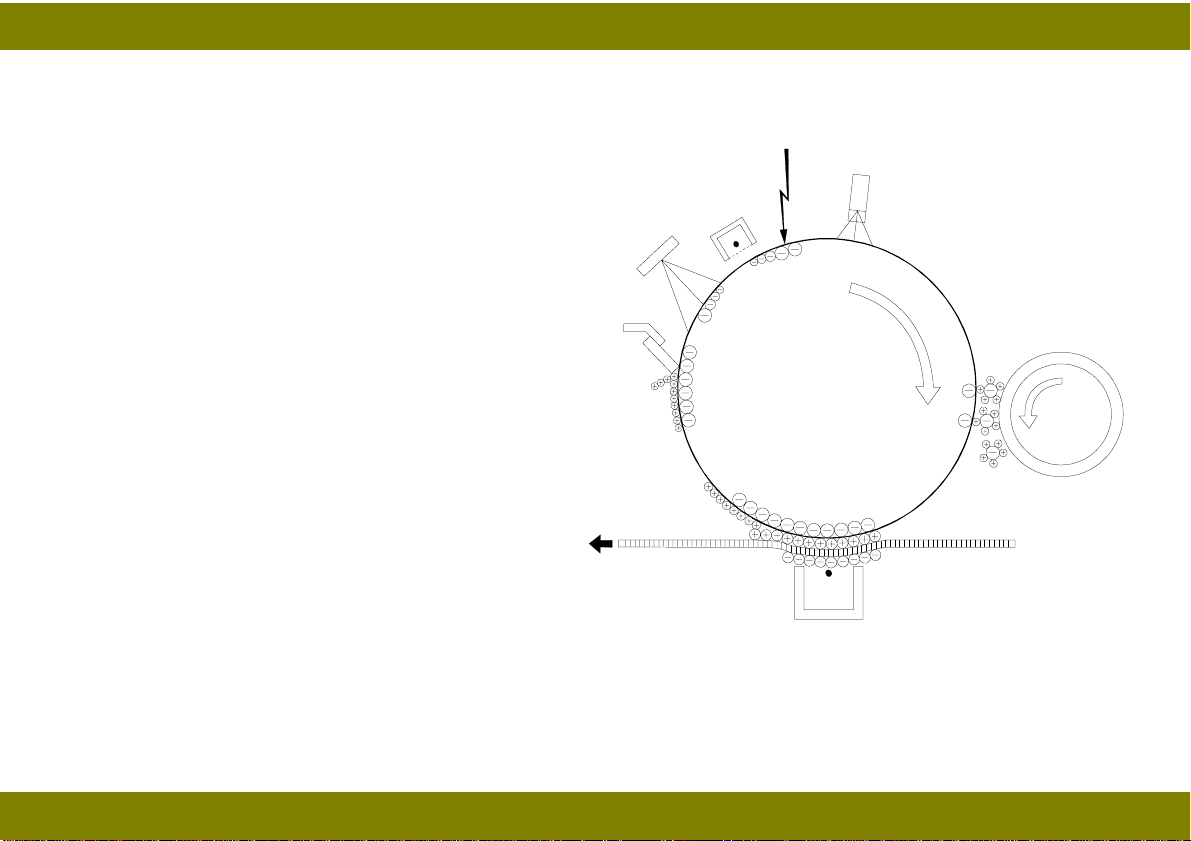
COPY PROCESSES AROUND THE DRUM
1. Drum Charge
In the dark, the charge corona unit gives a
uniform negative charge to the organic
7
2
3
photoconductor (OPC) drum. The charge
remains on the surface of the drum because the
OPC drum has a high electrical resistance in
the dark.
2. Exposure
6
4
An image of the original is reflected to the drum
surface via the optics assembly. The charge on
the drum surface is dissipated in direct
proportion to the intensity on the reflected light,
thus producing an electrical latent image on the
drum surface.
3. Erase
5
The erase lamp illuminates the area of the
charged drum surface tha t will not b e used for the copy image. The resistance of the drum in the
illuminated areas drops and the charge on those areas dissipates.
5
Page 9

April 8, 1998 COPY PROCESSES AROUND THE DRUM
4. Development
Positively charged toner is attracted to the negatively charged areas of the drum, thus developing the
latent image. (The positive triboelectric charge is caused by friction between the carrier and toner
particles.)
5. Image Transfer
Paper is fed to the drum surface at the proper time so as to align the copy paper and the developed
image on the drum surface. Then, a strong negative charge is applied to the back side of the copy
paper, producing an electrical force which pulls the toner particles from the drum surface to the copy
paper. At the same time, the copy paper is electrically attracted to the drum surface.
6. Cleaning
The cleaning blade scrapes any toner that was not transferred off of the drum.
7. Quenching
Light from the quenching lamp electrically neutralizes the drum surface.
6
Page 10
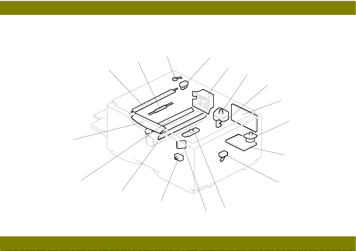
April 8, 1998 MECHANICAL COMPONENT LAYOUT
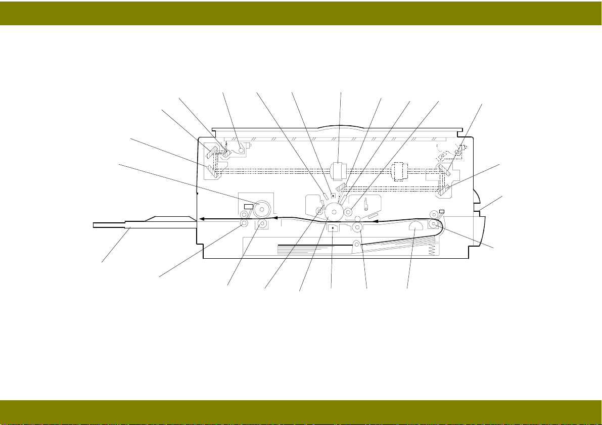
MECHANICAL COMPONENT LAYOUT
21
22
23
20
2
1
3 4 5 6
19
18
17
7
8 9
141516
10
11
12
13
7
Page 11

April 8, 1998 MECHANICAL COMPONENT LAYOUT
nd
1. 2
mirror
9. Development roller
17. Drum
2. 1st mirror
3. Exposure lamp
4. Quenching lamp
5. Charge corona unit
6. Lens
7. 6th mirror
8. Erase lamp
10. 4th mirror
11. 5th mirror
12. By-pass feed table
13. Relay rollers
14. Paper feed rollers
15. Registration rollers
16. Transfer corona unit
18. Cleaning blade
19. Pressure roller
20. Exit rollers
21. Copy tray
22. Hot roller
23. 3rd mirror
8
Page 12
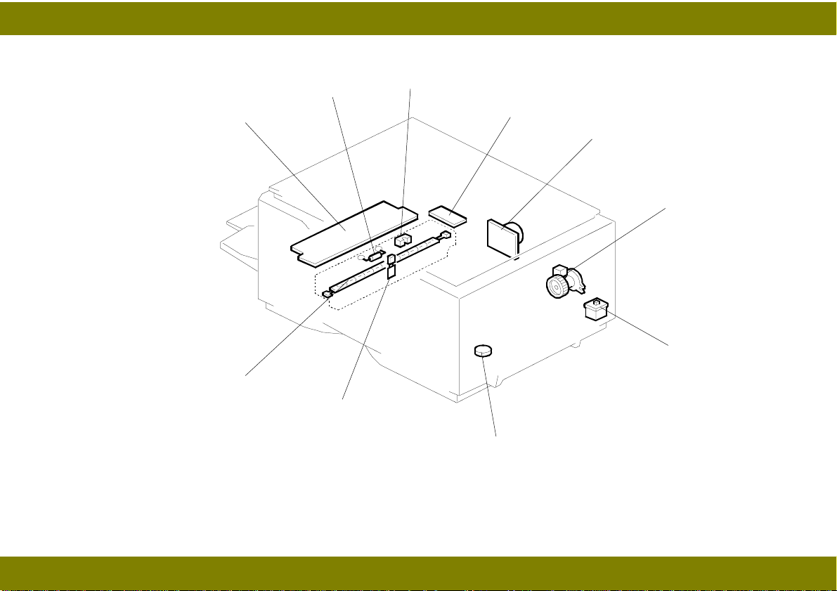
April 8, 1998 ELECTRICAL COMPONENT LAYOUT
ELECTRICAL COMPONENT LAYOUT
17
16
2
3
1
15
14
4
13
5
6
7
8
9
10
11
12
9
Page 13
April 8, 1998 ELECTRICAL COMPONENT LAYOUT
18
27
19
20
21
22
23
24
26
25
10
Page 14

April 8, 1998 ELECTRICAL COMPONENT DESCRIPTIONS
ELECTRICAL COMPONENT DESCRIPTIONS
Refer to the electrical component layout and the point-to-point diagram on the waterproof foldout
sheet for symbols and index numbers.
Symbol Name Function Index No.
Motors
M1 Main Motor Drives all the main unit components
except for the optics unit and fans.
M2 Exhaust Fan Motor Removes heat from around the fusing
unit and blows the ozone built up
around the charge corona unit to the
ozone filter. Prevents build-up of hot air
in the optics cavity.
M3 Scanner Drive Motor Drives the scanners (1st and 2nd). 6
M4 Lens and Mirror Motor
(A227 machines only)
Clutches
CL1 Paper Feed clutch Transfers main motor drive to the
Switches
SW1 Interlock Switch Cuts all power when the upper unit is
SW2 VL Switch Changes the light intensity of exposure
Moves the lens and 4th/5th mirror
positions in accordance with the
selected magnification.
paper feed roller.
opened.
lamp.
22
5
9
23
24
14
11
Page 15

April 8, 1998 ELECTRICAL COMPONENT DESCRIPTIONS
Sensors
S1 ADS Sensor Detects the background density of the
original.
S2 Registration Sensor Detects paper end condition. Checks if
paper is set on the by-pass feed table.
S3 Lens and Mirror H. P.
Sensor (A227
machines only)
Informs the CPU when the lens and
th/5th
mirror assembly are at the home
4
position (full size position).
S4 Scanner H. P. Sensor Informs the CPU when the 1st scanner
is at the home position.
S5 Toner End Sensor Detects toner end condition. 12
S6 Exit Sensor Detects misfeeds. 20
Solenoid
SOL1 Registration Solenoid Releases the stopper, synchronizing
the paper-feed timing with the original
scan.
Printed Circuit Boards
PCB1 Main Control Board Controls all copier functions. 8
PCB2 Power Pack Provides high voltage for the charge
corona, transfer corona, and
development bias.
PCB3 Power Supply Board Generates 5 Vdc and 24 Vdc outputs
from 120 Vac or 230 Vac inputs. Drives
the exposure lamp, fusing lamp, and
main motor.
13
11
7
4
25
10
18
12
Page 16

April 8, 1998 ELECTRICAL COMPONENT DESCRIPTIONS
PCB4 Operation Panel Board Informs the CPU of the selected
modes and displays the machine
condition on the panel.
PCB5 Noise Filter Removes electrical noise from the
input power.
Lamps
L1 Exposure Lamp Applies high intensity light to the
original for exposure.
L2 Fusing Lamp Provides heat to the hot roller. 27
L3 Quenching Lamp (QL) Neutralizes any charge remaining on
the drum surface after cleaning.
L4 Erase Lamp Discharges the drum outside of the
image area. (Provides leading/trailing
edge and side erase.)
Others
TH1 Optics Thermistor Monitors the temperature around the
exposure lamp for overheat protection.
TH2 Fusing Thermistor Monitors the fusing temperature. 26
TF1 Exposure Lamp
Thermofuse
TF2 Fusing Thermofuse Provides back up overheat protection
CO Total Counter Keeps a count of the total copies
Provides back up overheat protection
around the exposure lamp.
in the fusing unit.
made. (option)
17
21
1
16
15
3
2
19
—
13
Page 17

April 8, 1998 DRUM
DETAILED DESCRIPTIONS
DRUM
OPC DRUM CHARACTERISTICS
The OPC (Organic Photoconductor) Drum used in this machine is small in diameter (30 mm),
ensuring good paper separation. An OPC drum has the characteristics of:
1. Being able to accept a high negative electrical charge in the dark. (The electrical resistance of a
photoconductor is high in the absence of light.)
2. Dissipating the electrical charge when exposed to light. (Exposure to light greatly increases the
conductivity of a photoconductor.)
3. Dissipating an amount of charge in direct proportion to the intensity of the light. That is, where
stronger light is directed to the photoconductor surface, a smaller voltage remains on the drum.
4. Being less sensitive to changes in temperature (when compared to selenium F type drums).
5. During the drum’s life, drum residual voltage gradually increases and the photoconductive
surface becomes worn. Therefore, some compensation for these characteristics is required.
14
Page 18

April 8, 1998 CHARGE
CHARGE
OVERVIEW
This machine uses a single wire scorotron to charge
the drum. The corona wire [A] generates a corona of
negative ions when the power pack applies a negative
voltage (approximately -4.7 kV). The stainless steel
grid plate [B] ensures that the drum coating receives a
uniform negative charge (-880 V applied by the power
pack) as it rotates past the corona.
The charge corona unit contains a wire cleaner for
user maintenance.
[A]
[B]
15
Page 19
April 8, 1998 CHARGE
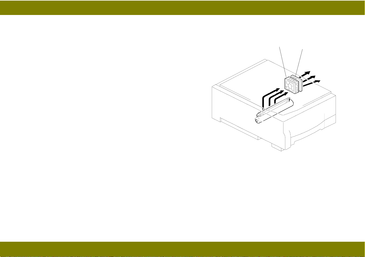
EXHAUST FAN AND OZONE FILTER
The exhaust fan [C] causes a flow of air through the
charge corona section. This prevents an uneven build-up
of negative ions that can cause uneven image density.
The exhaust fan also cools the optics cavity.
An ozone filter [D], which adsorbs ozone (O3) generated
by the charge corona, is located behind the exhaust fan.
The ozone filter decreases in efficiency over time as it
adsorbs ozone. The expected life of the ozone filter is
30k copies.
[C]
[D]
16
Page 20
April 8, 1998 OPTICS
OPTICS
OVERVIEW
During the copy cycle, an image of the original on the exposure glass is reflected onto the drum
surface through the optics assembly.
This machine has five (metric version) or four (inch version) standard reproduction ratios (A227
machine only), and reproduction ratios in one-percent steps from 70% to 141% by zoom function. A
stepper motor is used to change the positions of the lens and the 4th/5th mirrors to enlarge/reduce
17
Page 21

April 8, 1998 OPTICS
the image perpendicular to the scanning direction. Changes in reproduction ratio in the scanning
direction are achieved by changing the scanner speed (A227 machine only).
The CPU monitors the temperature around the optics through a thermistor that is located on the
scanner frame. When the temperature reaches 43°C, the machine stops copying and displays “U1”
on the operation panel. Then the machine moves the scanner to the return position, turns off the
fusing lamp, and starts rotating the exhaust fan faster to cool the optics cavity. After the temperature
drops below 40°C, the machine returns the scanner to the home position, turns on the fusing lamp,
and rotates the fan at the normal speed.
Additionally, a thermofuse on the first scanner provides back up overheat protection. It opens if the
temperature reaches 128°C and cuts ac power to the exposure lamp.
18
Page 22
April 8, 1998 OPTICS
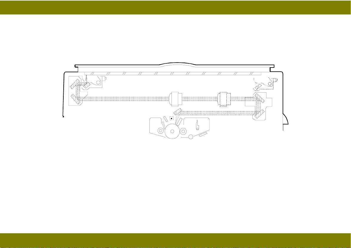
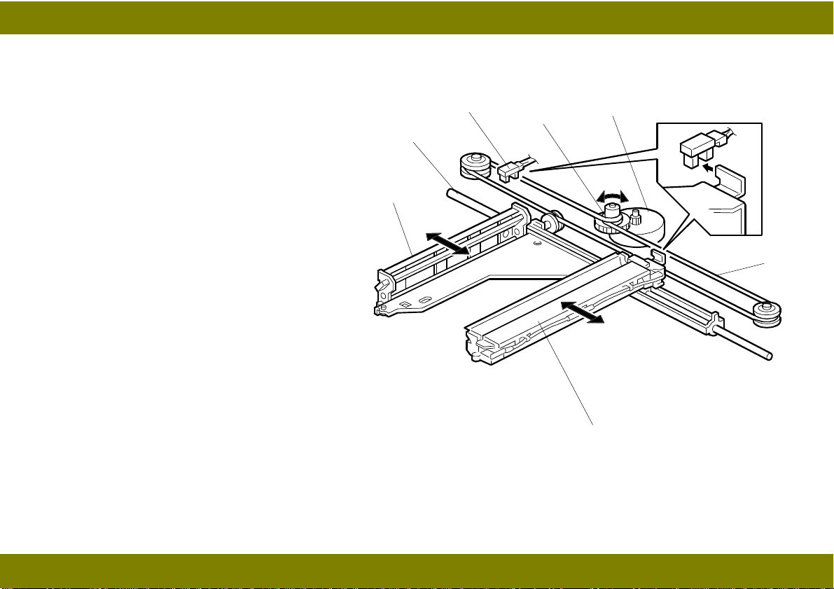
SCANNER DRIVE
A stepper motor [A] is used to drive the
scanner.
The first scanner [B] consists of the
exposure lamp and the first mirror. The
second scanner [C] consists of the second
and third mirrors. The scanner drive motor
drives the first and second scanners using
a scanner drive wire [D] via a pulley [E].
Both of the scanners move along the
guide rod [F]. The second scanner speed
is a half of the first scanner speed.
The home position sensor [G] detects
when the scanner is at the home position.
The scanner return position is determined
by counting the scanner motor drive
pulses.
[C]
[F]
[G]
[E]
[A]
[D]
[B]
19
Page 23
April 8, 1998 OPTICS
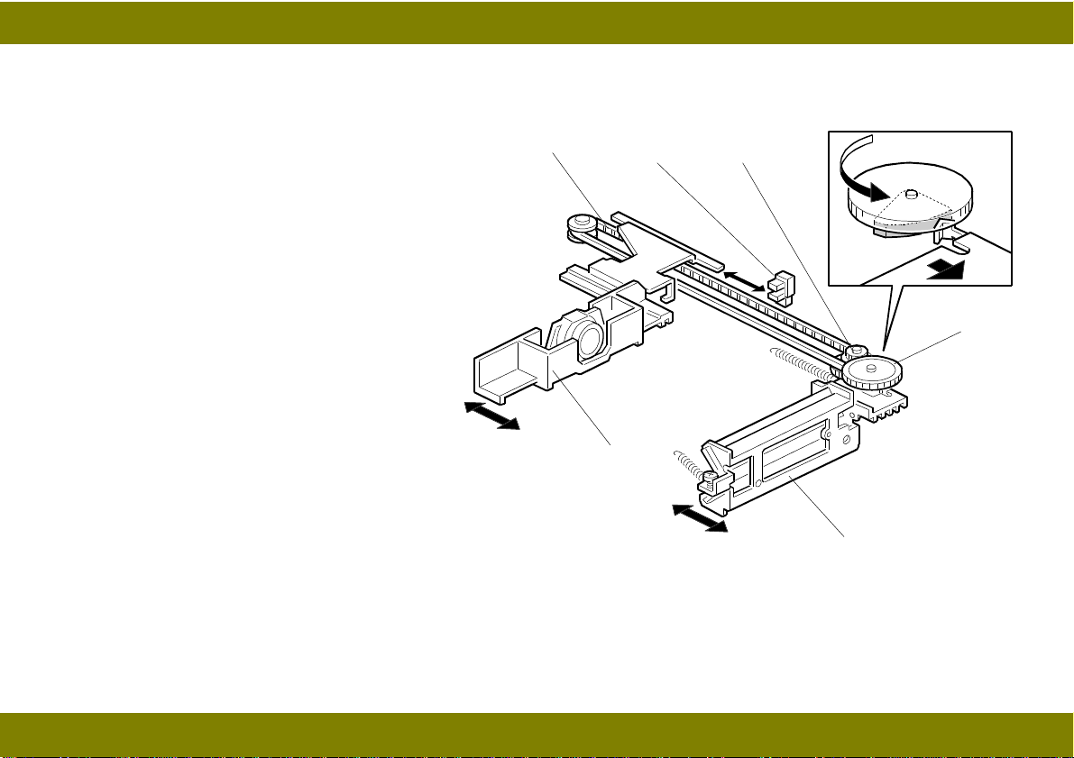
LENS AND 4TH/5TH MIRROR DRIVE (A227 MACHINE ONLY)
Drive from the lens motor [A] is
transmitted to the timing belt [B] on
which the lens unit [C] is clamped. The
lens position is changed to provide the
proper optical distance between the lens
and the drum surface corresponding to
the selected reproduction ratio. The
home position sensor [D] detects when
the lens is at its home position. The main
control boards keeps track of the lens
position based on the number of pulses
sent to the lens motor.
Drive from the lens motor is also
transmitted to the 4th/5th-mirror drive
cam [E]. As the lens unit position is
changed, the cam rotates to change the
4th/5th-mirror [F] position to provide
proper the focal distance between the
lens and the drum surface.
[B]
[C]
[D]
[A]
[E]
[F]
20
Page 24
April 8, 1998 OPTICS
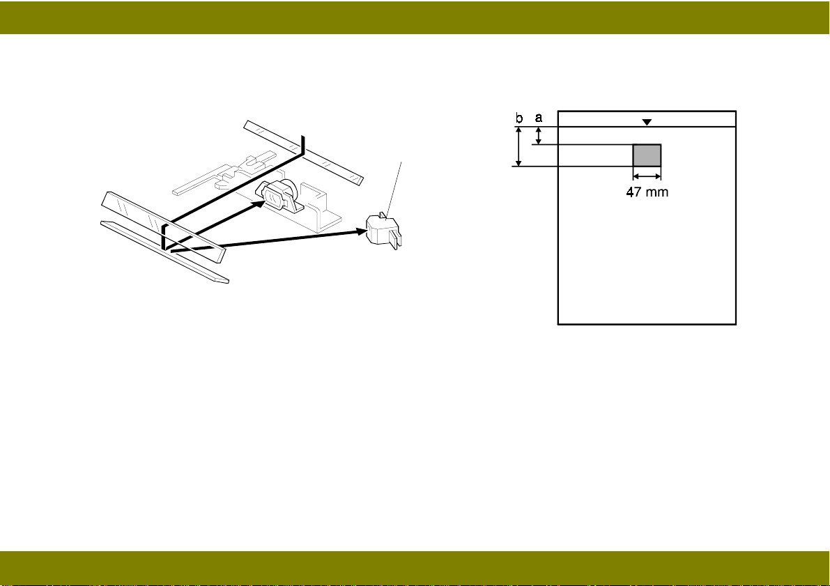
AUTOMATIC IMAGE DENSITY CONTROL SYSTEM (ADS)
[A]
In ADS mode, the original background density is sensed by the ADS sensor [A] and the CPU
determines an appropriate development bias voltage for the original to prevent dirty background from
appearing on copies.
The sensor, a photodiode, is mounted on the upper front frame. The sensor cover has a hole to allow
the light reflected from the original to fall directly onto the sensor.
Sampling starts 6 millimeters “a” from the leading edge of the original and continues for 15.0
millimeters “b” from the leading edge of original in full size mode. These lengths “a” and “b” will vary
depending on the selected reproduction ratio.
21
Page 25

April 8, 1998 OPTICS
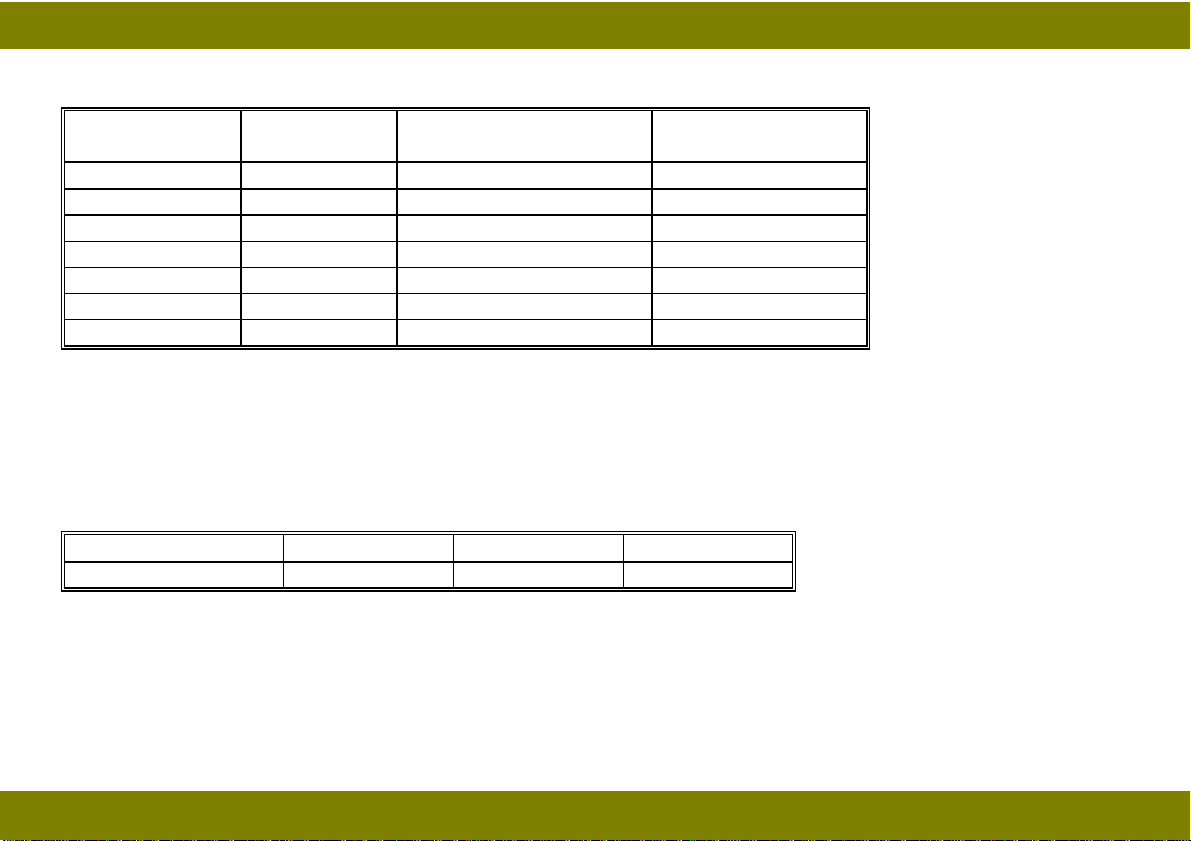
The photosensor circuit converts the light intensity to a voltage. The detected voltage is amplified
and sent to the main control board. The output from the sensor is adjusted to 2.5 volts for a normal
white original. The sensor outputs a lower voltage as less light is reflected from the original (the
background is darker). The CPU compares the maximum detected voltage with the ADS reference
voltage (2.5 ± 0.2 volts) and compensates the copy image density by changing the development bias
voltage.
22
Page 26

April 8, 1998 OPTICS
EXPOSURE LAMP VOLTAGE CONTROL
The main board controls the exposure lamp voltage through the power supply board. The copy
image density is controlled by the lamp intensity and development bias.
This section explains how the exposure lamp voltage control affects the copy image density.
Base Lamp Voltage Setting
The base lamp voltage is determined by the SP48 setting.
Base Lamp Voltage =
SP48 value x 0.5 (120 V machines)
SP48 value x 1.0 (230 V machines)
The default settings (may not equal to factory settings) of SP48 are:
128
for 120 V machines (= 64 V)
120
for 230 V machines (= 120 V)
Increasing the value makes the copy image lighter.
The maximum value of the lamp voltage setting including compensation factors (see following) is 180
for 230-volt models and 194 for 120-volt models. For 120-volt machines, the actual lamp voltage is
one-half the lamp voltage setting; therefore, the maximum lamp voltage is 97 volts. For 230-volt
machines the actual lamp voltage is the same as the lamp voltage setting; so, the maximum voltage
is 180 volts.
23
Page 27

April 8, 1998 OPTICS
Compensation Factors
The base lamp voltage is shifted by several factors as discussed in the following sections.
NOTE:
In the following tables, the default settings are in bold type.
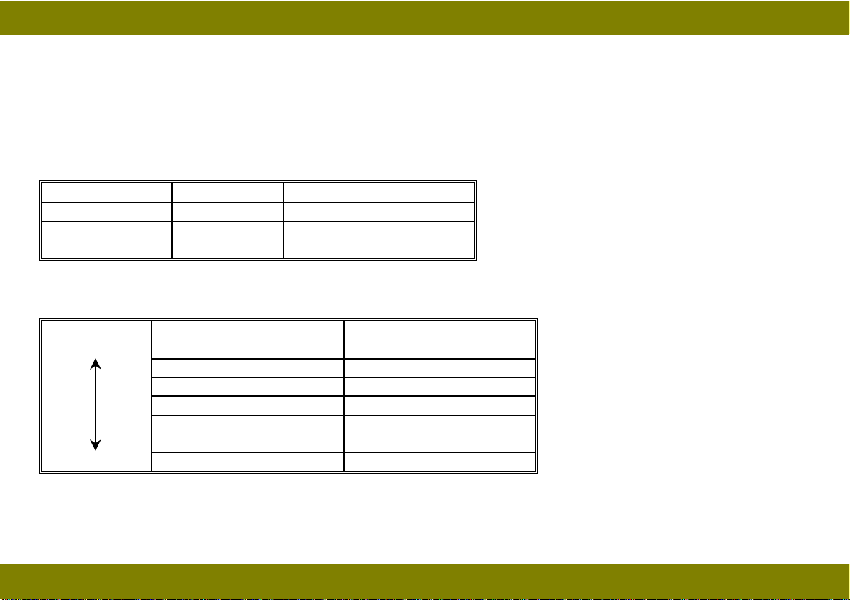
1. Reproduction Ratio Correction
The exposure lamp voltage increases or decreases depending on the magnification ratio. This
compensates for the change in concentration of light on the drum.
Magnification Ratio Exposure Lamp
70% to 99% -1 step
100% 0
101% to 141% +1 step
2. Image Density Adjustment Setting (SP34)
SP34 can adjust the copy image density to adapt the machine to its operating environment.
Depending on the SP34 setting, both the exposure lamp voltage and the development bias may
change.
24
Page 28
April 8, 1998 OPTICS
SP34 (This can also be changed by UP1.)
SP34 Setting Setting Exposure Lamp
Voltage Change
0Normal 0 0
1 Light 0 -40 V
2 Dark 0 +40 V
3 Lighter +3 steps -40 V
4 Darker -3 steps +40 V
5 Lightest +7 steps -40 V
6 Darkest -7 steps +40 V
Development
Bias Change
1 step = 0.5 V (120 V machines) or 1.0 V (230 V machines)
3. Image Density Setting Position
The operation panel has four image density level positions. Depending on the position, the exposure
lamp base voltage is changed. (ADS is the default.)
Photo Mode Darker ADS Lighter
0 - 6 steps 0 + 6 steps
In the photo mode, the exposure lamp voltage is unchanged; however, the development voltage is
changed to improve the copy image for halftone originals. (Refer to Development section.)
25
Page 29
April 8, 1998 OPTICS
(Image Density Adjustment At Darker Setting Position)
There are two SP modes which can adjust the image density when the “Darker” position is selected
on the operation panel.
Both SP modes change the exposure lamp voltage as shown below.
SP35: Coarse Adjustment (This can also be changed by the UP2)
SP35 Setting Setting Exposure Lamp Voltage
0 Normal -6 steps
1 Darker -8 steps
2 Darkest -10 steps
SP38: Fine Adjustment
Setting SP38 Setting Lamp Voltage Change
Darkest 0 -3 steps
1 -2 steps
2 -1 step
30
4 +1 step
5 +2 steps
Lightest 6 +3 steps
26
Page 30
April 8, 1998 OPTICS
(Image Density Adjustment at Lighter Setting Position)
There are two SP modes which can adjust the image density when the “Lighter” position is selected
on the operation panel.
Only the SP mode (SP39) for the fine adjustment of the image density changes the exposure lamp
voltage. The coarse adjustment (SP36) changes the development bias (see Development section).
SP39: Fine Adjustment
Setting SP39 Setting Lamp Voltage Change
Darkest 0 -3 steps
1 -2 steps
2 -1 step
30
4 +1 step
5 +2 steps
Lightest 6 +3 steps
(Image Density Adjustment At Photo Mode Position)
The image density in the Photo mode can be changed by the SP64.
The exposure lamp voltage and the base development bias are changed by SP64 as shown in the
table.
SP64 (This can also be changed by UP4.)
27
Page 31

April 8, 1998 OPTICS
Settings No. Base Bias Voltage Exposure Lamp
Change
Lightest 0 -270 V +4 steps
1 -270 V +2 steps
2 -270V 0
3 -230 V 0
4 -210 V 0
Darkest 5 -190 V 0
4. VL Correction
The light intensity may decrease because of dust accumulated on the optics parts. Additionally, the
drum sensitivity gradually decreases during the drum’s life. This may cause dirty background on
copies. This is automatically compensated for by the VL correction.
The exposure lamp voltage is increased by +1.0 volts (230-V machines), or +0.5 volts (120-V
machines) at the set copy count interval. The VL correction counter tracks the copy count interval.
Note that if the VL counter is cleared, an improper correction will be applied. The table below shows
the relationship between the SP setting and the interval.
28
Page 32

April 8, 1998 OPTICS
SP63 Setting Exposure Lamp Voltage Special UP31
0 +1 step/4000 copies 0
1 +1 step/3000 copies 1
2 +1 step/2500 copies 2
3 +1 step/2000 copies 3
4 +1 step/1500 copies 4
5 +1 step/1000 copies 5
6 +1 step/500 copies 7 +1 step/250 copies 8 No Correction -
(Special UP Modes)
There are thirteen user program modes on this model (refer to the operator’s manual and UP mode
and SP mode cross-reference table). The operator’s manual, however, explains only eight modes of
them.
The UP modes numbered from 30 to 34 are special UP modes. If it is necessary to change any
settings related to the special UP modes, the service representative may ask the user to change it
and thus avoid a visit.
Please note that UP31 accepts settings only from 0 to 5.
29
Page 33

April 8, 1998 OPTICS
(VL Switch)
Depending on the environment, the default automatic VL correction may not be enough to correct
the image density. The VL switch is located on
the upper registration roller assembly in the
machine and allows the operator to correct image
density manually.
The exposure lamp voltage is increased
according to the VL switch position.
Position 0 Position 1 Position 2
0
+10 steps +20 steps
The amount of increase in each position can be changed by SP62 as shown below:
SP62 Setting Special UP Mode Exposure Lamp Voltage
UP32 SW Position 0 SW Position 1 SW Position 2
0 0 0 +10 steps +20 steps
1 1 0 +5 steps +10 steps
2 2 0 +15 steps +30 steps
3 3 0 +20 steps +40 steps
30
Page 34

April 8, 1998 ERASE
ERASE
OVERVIEW
The erase lamp [A], which is installed in
the upper unit, consists of a single row of
LEDs extended across the full width of the
drum. The erase lamp has the following
functions:
• Leading edge erase
• Side erase (A227 machines only)
• Trail edge erase
abcdefg abcdefgh
[A]
31
Page 35

April 8, 1998 ERASE
LEAD EDGE ERASE
The entire line of LEDs turns on when the main motor turns on. They stay on until the erase margin
slightly overlaps the lead edge of the original image area on the drum (Lead Edge Erase Margin).
This prevents the shadow of the original edge from being developed on the copy. At this point, side
erase starts (A227 machines only). The width of the leading erase margin can be adjusted using
SP41.
SIDE ERASE (A227 MACHINES ONLY)
Based on the reproduction ratio, the LEDs turn on blocks (labeled “a” to “h” on the previous page).
This reduces toner consumption and drum cleaning load.
The CPU determines which blocks to turn on based on the selected reproduction ratio as follows.
Reproduction Ratio (%) Blocks ON
70 to 72 a - g
73 to 76 a - f
77 to 80 a - e
81 to 85 a - d
86 to 88 a - c
89 to 92 a - b
93 to 97 a
98 to 100 All Off
32
Page 36

April 8, 1998 ERASE
TRAILING EDGE ERASE
This minimizes toner consumption.
The entire line of LEDs turns on after the trailing edge of the latent image has passed 10 mm from
the erase lamp. The length of the latent image is determined by the paper length, which is checked
by the registration sensor. The LEDs stay on to erase the leading edge of the latent image in the next
copy cycle. After the final copy, the erase lamps and the main motor turn off at the same time.
33
Page 37

April 8, 1998 development
DEVELOPMENT
OVERVIEW
The development unit is contained in
the CTDM (Cleaning Toner Development Magazine). When the main motor
turns on, the development roller [A] and
agitator [B] start turning.
There are permanent magnets in the
development roller which attract the
developer to the roller. The turning
sleeve of the development roller carries
the developer past the doctor blade,
which trims the developer to the desired
thickness.
The development roller sleeve continues to turn, carrying the developer to the drum [C]. When the
developer brush contacts the drum surface, the negatively charged areas of the drum surface attract
and hold the positively charged toner. In this way, the latent image is developed. The amount of
toner consumed during development is supplied from the toner bottle automatically.
[A]
[C]
[D]
[B]
The development roller is given a suitable negative bias to prevent toner from being attracted to the
non-image areas, which may have a residual negative charge. The bias also controls image density.
The toner end sensor [D] detects when toner in the CTDM has run out.
34
Page 38

April 8, 1998 development
TONER SUPPLY MECHANISM
Before the two seals [A, B] and are
removed from a new CTDM, the developer
is divided into six cells to prevent developer
in it from biasing during shipment. Toner
and developer mix when the seals are
removed. Whenever a new CTDM is
installed into the machine, CTDM initialization must be performed to mix the toner
and developer evenly, and create the
triboelectric charge.
CTDM initialization is performed at the
following times:
• when the main switch is turned off and on at the toner end condition
• when the upper cover is opened and closed at the toner end condition
• SP12 is performed
[A]
[C]
[B]
[D]
NOTE:
CTDM initialization must be performed by using SP12 if the CTDM is replaced when the
toner end condition does not exist.
The developer case is full of developer and toner after CTDM initialization. Toner density in the
developer case [C] is kept uniform all the time since the amount of consumed toner is supplied from
the toner case [D] automatically.
35
Page 39

April 8, 1998 development
DEVELOMENT BIAS FOR IMAGE DENSITY CONTROL
Image density is controlled by changing two items—the amount of bias voltage applied to the
development roller sleeve, and the amount of voltage applied to the exposure lamp.
Applying a bias voltage to the development sleeve reduces the potential between the development
roller and the drum, thereby reducing the amount of toner transferred. As the bias voltage becomes
greater, the copy becomes lighter.
The method of control depends on whether the image density is manually selected or auto image
density is used.
Base Bias Voltage in Each Image Density Mode
The base bias voltage for non-image areas (between copies) is fixed at -150 Volts. This value is
also be compensated by the factors explained later.
The base bias voltage for image areas is determined according to the setting of the image density
mode. The following table shows the base development bias. The exposure lamp base voltage
correction value is included as a reference.
Photo Mode Darker ADS Lighter
Base Bias -230 V -150 V -150 V -190 V
Exposure Lamp Voltage 0 -6 steps 0 +6 steps
36
Page 40

April 8, 1998 development
Compensation Factors
1. Automatic Image Density (ADS) Mode
In ADS mode, the exposure lamp base voltage is fixed at a value that is determined by SP48 (see
Optics section). Image density is controlled by changing only the development bias voltage.
The bias voltage for ADS mode depends on the background image density of the original as
measured by the ADS sensor.
The CPU checks the voltage output from the automatic ID circuit. This circuit has a peak hold
function. The peak hold voltage corresponds to the maximum reflectivity of the original. The CPU
then determines the proper development bias level with reference to the peak hold voltage.
The table below shows the ratio of the ADS voltage (actual original background density) to the ADS
reference voltage (standard white background density) and the development bias voltage.
ADS Voltage Ratio (%) Development Bias Voltage
80 to 100 (light) -150 V
73 to 79 -190 V
60 to 72 -230 V
30 to 59 -270 V
0 to 29 (dark) -290 V
37
Page 41

April 8, 1998 development
2. Image Density Adjustment Setting (SP34)
Based on SP34, compensation will be applied to the development base bias voltage as shown in the
following table. This compensation is applied to all the image density adjustment positions.
SP34 (This can also be changed by UP1)
SP34 Setting Setting Development
Bias Change
0Normal +0 V 0
1 Light -40 V 0
2 Dark +40 V 0
3 Lighter -40 V +3 steps
4 Darker +40 V -3 steps
5 Lightest -40 V +7 steps
6 Darkest +40 V -7 steps
Exposure Lamp
Voltage Change
NOTE:
The value in the list will be added to the base bias voltage.
Example)
Operation panel set to “Darker”
Base bias voltage = -150 Volts
SP34 Setting = 3
Development bias = -150 + (-40) = -190 Volts
38
Page 42

April 8, 1998 development
3. Image Density Adjustment at Lighter Setting Position (SP36)
SP36 can change the base bias voltage when the “Lighter” position is selected on the operation
panel.
SP36 (This can also be changed by UP3)
SP36 Setting Image Density Base Bias Voltage at Lighter Position
0 Normal -190 V
1 Lighter -230 V
2 Lightest -270 V
4. Photo Mode Correction (SP64)
The image density in the Photo mode can be changed by the SP64 as shown in the following table.
SP64 (This can also be changed by UP4)
No. Setting Base Bias Voltage Exposure Lamp
0 Lightest -270 V +4 steps
1 Lighter -270 V +2 steps
2 Light -270V 0
3 Normal -230 V
4 Dark -210 V 0
5 Darker -190 V 0
0
39
Page 43

April 8, 1998 development
TONER END CONDITION
Toner end condition is determined by the toner end sensor, which is located below the toner bottle of
the CTDM.
Toner Near-end Condition
While the main motor is rotating, the machine monitors the voltage output from the toner end sensor.
The voltage from the sensor is high when the toner bottle of the CTDM is full and becomes low when
the toner bottle is almost empty.
If the CPU detects a low output from the toner end sensor more than 3 times in a row, the CPU starts
to blink the Replace CTDM indicator (). This is the toner near-end condition. After it detects this
condition, the machine can make 50 copies.
The machine clears the toner near-end condition if the output from the toner end sensor goes back
high for 5 seconds.
Toner End Condition
If the machine makes more 50 sheets of copies during toner near-end condition or the CPU detects
a low output for more than 5 seconds, it disables copying and lights the Replace CTDM indicator
().
40
Page 44

April 8, 1998 development
The machine clears the toner end condition if the output from the toner end sensor goes back high
for 5 seconds.
Toner End Recovery
Replacing the CTDM clears the toner end condition. If the main switch is turned off and back on, or
the upper cover is opened and closed during the toner near-end condition or toner end condition, the
machine expects that the CTDM has been replaced. It then rotates the main motor for CTDM
Initialization, and then the CPU monitors an output from the sensor. The machine clears the toner
end condition if the CPU detects a high output from the toner end sensor for more than 5 seconds.
NOTE:
1) The machine also detects the toner end condition when the CTDM is
not installed in it.
2) CTDM initialization can be executed using SP12.
41
Page 45

April 8, 1998 IMAGE TRANSFER
IMAGE TRANSFER
A high negative voltage (approximately -5.5 kV) is applied to the transfer corona wire [A] by the power pack,
and the corona wire generates negative ions. These negative ions are
applied to the back side of the copy
paper. This negative charge forces the
paper against the drum and attracts
the positively charged toner onto the
paper.
The paper separates from the drum
automatically because of the drum’s
small diameter. Due to the paper’s
stiffness, it cannot make the sharp
turn and separates without any assistance. This is sometimes referred to
as
curvature separation
.
[A]
42
Page 46

April 8, 1998 DRUM CLEANING
DRUM CLEANING
The cleaning unit and the used toner
tank are contained in the CTDM.
A counter blade system is used for drum
cleaning. The cleaning blade [A] scrapes
off any toner remaining on the drum
after the image is transferred to the
paper.
There is no used toner overflow
detection mechanism because the used
toner tank is large enough for the
lifetime of the CTDM.
[A]
43
Page 47

April 8, 1998 QUENCHING
QUENCHING
[A]
In preparation for the next copy cycle, light from the quenching lamp (LEDs) [A] neutralizes any
charge remaining on the drum. The quenching lamp is installed on the charge corona unit.
44
Page 48

April 8, 1998 PAPER FEED AND REGISTRATION
PAPER FEED AND REGISTRATION
OVERVIEW
This machine has one paper feed station and a
by-pass feed table.
The paper feed station uses a paper tray [A]
which can hold 250 sheets. The by-pass feed
table [B] can hold 1 sheet.
The paper tray uses two semicircular feed
rollers [C] and a corner separator. The
semicircular feed rollers make one rotation to
drive the top sheet of the paper stack to the
relay rollers [D].
The paper tray has two corner separators,
which allow only one sheet to feed. They also
serve to hold the paper stack.
If a sheet of paper is set on the by-pass feed
table, the registration sensor [E] is actuated and
the machine goes to by-pass feed mode.
[D]
[E]
[A]
[B][C]
45
Page 49

April 8, 1998 PAPER FEED AND REGISTRATION
PAPER FEED MECHANISM
The main motor rotation is transmitted to the paper feed
clutch gear [A] though several gears. The rotation of the
paper feed clutch gear is transmitted to the relay roller
gear [B] through an idle gear.
After the Start key is pressed, the solenoid [C] of the
paper feed clutch is energized to release the stopper [D],
and the rotation of the relay roller gear is transmitted to
the feed roller shaft [E]. The solenoid stays on for 250
milliseconds and then turns off. The feed rollers stop
when they complete one rotation.
Before the feed rollers stop, the relay rollers [F] catch the
leading edge of the paper and continue feeding it.
[C]
[A]
[E]
[D]
[B]
[F]
46
Page 50

April 8, 1998 PAPER FEED AND REGISTRATION
REGISTRATION MECHANISM
The relay rollers always rotate while the main
motor rotates. They transport the paper to
the registration rollers [A]. The registration
rollers are also driven by the main motor
through idle gears.
There is a paper stopper [B] between the
relay rollers and the registration rollers. After
the leading edge of the paper reaches the
stopper, it buckles slightly to remove skew.
Then, 2.9 seconds after the paper feed
clutch is turned on, the registration solenoid
[C] is energized to release the stopper,
synchronizing the paper feeding with the
image on the drum. After 0.6 seconds, the
registration solenoid is de-energized.
The registration sensor detects paper length
and paper end.
[A]
[B]
[C]
47
Page 51

April 8, 1998 PAPER FEED AND REGISTRATION
BY-PASS FEED
[C]
[B]
[A]
[D]
If a sheet of paper is inserted in the by-pass feed table [A], the registration sensor [B] is actuated and
the machine goes to by-pass feed mode. 300 milliseconds after the registration sensor is actuated,
the main motor turns on for 230 milliseconds to drive the relay roller [C] to catch the leading edge of
the paper. The relay roller then transports the paper to the registration roller [D]. The registration
solenoid is energized 2358 milliseconds after the main motor starts rotating.
48
Page 52

April 8, 1998 PAPER FEED AND REGISTRATION
PAPER FEED AND MISFEED DETECTION TIMING
%&
" #$
!
The registration sensor and the exit sensor are used for misfeed detection. If the CPU detects a
misfeed, the Check Paper Path indicator () turns on or “PE” is displayed on the copy counter.
When the main switch is turned on, the CPU checks these sensors for initial misfeed.
During the copy cycle, the CPU performs four kinds of misfeed detection:
49
Page 53

April 8, 1998 PAPER FEED AND REGISTRATION
PE: Checks whether the registration sensor is actuated within 1.2 seconds after the Start key is
pressed. Since this machine has no indicator or sensor to detect paper end, the “PE” indicator is
lit in the paper end condition as well.
” (1): Checks whether the copy paper has passed through the registration sensor 6.7 seconds after
the Start key is pressed.
” (2): Checks whether the exit sensor is actuated within 6.7 seconds after the Start key is pressed.
” (3): Checks whether the copy paper has passed through the exit sensor 12.4 seconds after the
Start key is pressed.
50
Page 54

April 8, 1998 IMAGE FUSING
IMAGE FUSING
OVERVIEW
[F]
After the image is transferred, the copy
paper enters the fusing unit. The image is
fused to the copy paper by the process of
heat and pressure through the use of a hot
roller [A] and pressure roller [B].
The CPU monitors the hot roller temperature
through a thermistor [C] that is in contact
with the hot roller surface. A thermofuse [D]
protects the fusing unit from overheating.
[H]
[E]
[A]
The hot roller strippers [E] separate the copy
paper from the hot roller and direct it to the
exit rollers. The exit sensor [F] monitors the
progress of the copy paper through the
fusing unit and acts as a misfeed detector.
The exit rollers drive the copy paper to the
copy tray.
When the upper unit is closed, the pressure roller is pushed up by the arms [G]. The springs [H] of
front and rear apply the proper fusing pressure between the hot roller and the pressure roller.
[G]
[B]
[D]
[C]
51
Page 55

April 8, 1998 IMAGE FUSING
FUSING LAMP CONTROL
The CPU monitors the temperature of the hot roller surface using a thermistor. The fusing lamp is
turned on and off to keep the hot roller surface at the target temperature. The target temperature
depends on the machine condition as follows.
200 C°
160 C°
150 C°
Room Temp.
Fusing
Lamp
ON
OFF
M ain SW is tu r n e d o n
Copy starts
Pa p e r fe e d s tarts
Start key is pressed
Copy finishes
52
Page 56

April 8, 1998 IMAGE FUSING
Machine Condition Fusing Lamp
After the main switch is turned on
and the fusing temperature has
°
reached 160
During copying
Within 30 minutes after copying is
finished
Over 30 minutes after copying is
finished
C.
ON/OFF Threshold
°
160
C
°
200
C
°
160
C
°
150
C
When the Start key is pressed
the red indicator lights and the
fusing temperature increases.
Paper feed starts after the fusing
temperature reaches 160
Remarks
°
C.
When the main switch is turned on, the CPU turns on the fusing lamp. When the fusing thermistor
detects 160°C, the machine enters the ready condition.
If the fusing temperature is higher than 160°C when the Start key is pressed, the machine starts
copying immediately. Otherwise, copying starts after the fusing temperature reaches 160°C. The
fusing temperature is controlled at 200°C during copying.
Within 30 minutes after copying is finished, the fusing temperature is controlled at 160°C. Over 30
minutes after copying is finished, the fusing temperature is controlled at 150°C. If auto shut off is
selected, the fusing lamp is turned off when the time selected by SP14 passes after copying is
finished.
53
Page 57

April 8, 1998 IMAGE FUSING
FUSING LAMP CONTROL CIRCUIT
Overview
The main control board monitors the fusing temperature through a thermistor to control the applied
power. Two fusing lamp control systems are provided for this machine.
On/Off Control
On
Off
A227D522.WMF
The voltage applied to the fusing lamp is the full duty cycle of the ac waveform. The power is applied
to the lamp until the operating temperature is reached.
54
Page 58

April 8, 1998 IMAGE FUSING
Phase Control Mode
Phase
A227D523.WMF
The amount of time that power is applied to the fusing lamp depends on the temperature of the hot
roller.
NOTE:
Overheat Protection
There is an overheat protection circuit in the main control board. If the hot roller temperature reaches
230°C, the resistance of the thermistor becomes too low. If the main control board detects this
condition for 3 seconds continuously, “E-53” is displayed on the operation panel and power to the
fusing lamp is cut.
Phase control mode is used only if the customer has a problem with electrical noise or
interference.
If the thermistor overheat protection circuit fails, the thermofuse opens when it reaches 169°C,
removing power from the fusing lamp.
55
Page 59

April 8, 1998 INSTALLATION REQUIREMENTS
INSTALLATION
INSTALLATION REQUIREMENTS
ENVIRONMENT
1. Temperature Range:
2. Humidity Range: 15% to 80% RH
3. Ambient Illumination: Less than 1,500 lux (Do not expose to direct
4. Ventilation: Minimum space 30 m3.
5. Ambient Dust: Less than 0.15 mg/m3 (4 x 10⁻³ oz/yd3)
6. If the place of installation is air-conditioned or heated, do not place the machine:
1) Where it will be subjected to sudden temperature changes.
2) Where it will be directly exposed to cool air from an air-conditioner.
3) Where it will be directly exposed to heat from a heater.
7. Do not place the machine where it will be exposed to corrosive gasses.
8. Do not install the machine at any location over 2,000 m (6,500 feet) above sea level.
10°C to 35°C (50°F to 95°F)
sunshine.)
Room air should turn over at least 3 times per hour
56
Page 60

April 8, 1998 INSTALLATION REQUIREMENTS
9. Place the machine on a strong and level base.
10. Do not place the machine where it may be subjected to strong vibration.
MACHINE LEVEL
1. Front to back: Within 3 mm (0.12") of level
2. Right to left: Within 3 mm (0.12") of level
57
Page 61

April 8, 1998 INSTALLATION REQUIREMENTS
MINIMUM SPACE REQUIREMENTS
Place the machine near the power source, providing clearance as shown:
M o r e th a n 2 0 c m (7.9 “ )
Machine
M o r e th a n
11 cm (4.3“ )
M o r e th a n 3 0 c m (11.8 “)
M o r e th a n
10 cm (3.9“)
58
Page 62

April 8, 1998 MACHINE INSTALLATION
POWER REQUIREMENTS
1. Input voltage level: 120 V, 60 Hz: More than 10 A
220 ~ 240 V, 50/60 Hz: More than 6 A
2. Permissible voltage
fluctuation:
Do not set anything on the power cord.
Make sure the plug is firmly inserted in the outlet.
Avoid multi-wiring.
10 %
MACHINE INSTALLATION
Refer to the procedure packed in the box with the machine or to the procedure in the operator’s
manual.
59
Page 63

April 8, 1998 SERVICE REMARKS
SERVICE TABLES
SERVICE REMARKS
GENERAL CAUTIONS
1. To prevent physical injury, keep hands away from the mechanical drive components when the
main switch is on (especially during the warm-up cycle). If the Start key is pressed before the
machine finishes the warm-up cycle, the Start key indicator starts blinking and the machine starts
making copies as soon as the warm-up cycle is completed.
2. Before disassembling or assembling any parts of the machine, make sure that the power cord is
unplugged.
3. To avoid possible injury or machine damage, always hold the upper unit firmly with one hand
while opening the upper unit or releasing the gas spring with the other.
4. Keep all the shipping retainers for future shipping use.
5. Do not loosen any of the paint-locked screws. Such screws are used for optic components, the
drum stay, and doctor blade of the CTDM.
6. Do not release the gas spring from the pin while the upper unit is closed. Otherwise the gas
spring will expand suddenly and may cause injury.
60
Page 64

April 8, 1998 SERVICE REMARKS
7. To prevent the upper unit from falling when separating the gas spring from it, hold the upper unit
firmly with one hand while releasing the gas spring with the other.
8. Do not leave the upper unit fully opened. Otherwise, the unit or whole machine may be fall over.
DRUM
1. Never expose the drum to direct sunlight.
2. Never touch the drum surface with bare hands. If the drum surface is touched with fingers or
becomes dirty, wipe it with a clean, dry cloth.
3. Never use alcohol to clean the drum; alcohol dissolves the drum surface.
4. Store the drum in a cool, dry place away from heat.
5. Take care not to scratch the drum as the drum’s surface layer is thin and easily damaged.
6. Never expose the drum to corrosive gasses such as ammonia gas.
7. Always keep the drum in its protective sheet when it is out of the machine.
CTDM (CLEANING TONER DEVELOPMENT MAGAZINE)
1. Place the CTDM on a clean and level place when it is out of the machine.
61
Page 65

April 8, 1998 SERVICE REMARKS
2. Do not turn the CTDM upside down. Toner and developer may fall from the unit.
3. Be careful not to damage the edge of the cleaning blade.
4. Do not store the CTDM under high temperature and high humidity conditions.
CHARGE CORONA UNIT
1. Do not touch the charge corona wire or grid plate with bare hands. Oil stains may cause uneven
image density on copies.
2. Clean the charge corona wire by sliding the wire-cleaning tool from front to rear.
3. Clean the charge grid with a blower brush (not with a cloth).
4. Clean the quenching lamp (LED) with a blower brush or a dry cloth.
ERASE LAMP
1. Clean the erase lamp with a blower brush or dry cloth.
62
Page 66

April 8, 1998 SERVICE REMARKS
OPTICS
1. Clean the exposure glass with glass cleaner and a damp cloth to reduce the amount of static
electricity on the glass surface.
2. Only use a clean soft cloth to clean the mirror and reflectors.
3. Only use a blower brush to clean the lens.
4. Do not touch the following parts with bare hands:
a) Reflectors
b) Exposure Lamp
c) Mirrors and Lens
5. Whenever cleaning the optics, all the following actions must be done in order.
a) Optics cleaning
b) SP95 (VL Correction Reset)
c) Copy Quality Adjustment
d) SP56 (ADS Reference Voltage Adjustment) See the SP mode table for details.
TRANSFER CORONA
1. Clean the corona wire by sliding the wire-cleaning tool from front to rear.
63
Page 67

April 8, 1998 SERVICE REMARKS
FUSING UNIT
1. Be careful not to damage the edges of the hot roller strippers.
2. Be careful not to damage the tension springs of the hot roller strippers.
3. Do not touch the fusing lamp with bare hands.
4. Make sure that both fusing lamp insulators are properly set in the holders, and that fusing lamp
does not touch the inner surface of the hot roller.
PAPER FEED
1. Do not touch the feed roller with bare hands.
2. The side fences and the end fence of the paper tray should be positioned correctly so that they
securely hold the paper. Otherwise, paper misfeeds may occur.
3. Avoid storing paper for a long time. At high temperature and high humidity, or at low temperature
and low humidity, store paper in a plastic bag. This is especially important to decrease the
amount of curling or waving of the paper that would lead to paper misfeeds.
64
Page 68

April 8, 1998 SERVICE REMARKS
OTHERS
1. When replacing the main control board, remove the EEPROM (IC105) from the old board and
replace it on the new board. Then install the new main board in the machine.
2. Never perform SP99 (Clear All Memory) except for the following two cases:
a) When the copier malfunctions due to a damaged EEPROM.
b) When using a brand-new EEPROM.
3. When SP99 is performed, copy quality may be affected. Adjust copy quality if necessary.
4. Tighten securely the screws used for grounding the following PCBs when reinstalling them.
• Main Control Board
• Power Supply Board
• High Voltage Power Pack
65
Page 69

April 8, 1998 PROGRAM MODES
PROGRAM MODES
BASIC OPERATION
Component
This machine is equipped with two program modes. One is the Service Program (SP) mode for
factory and field technician usage, and the other is the User Program (UP) mode for user usage.
These program modes have a different access procedures, but all the UP mode functions can be
accessed from the SP mode.
To make it possible to reset a service call (E5x) condition such as a fusing error using the SP mode,
the SP mode can be accessed while the error condition exists.
Operation
To access these program modes, a certain key must be held down while turning on the main switch.
After accessing, select the required mode number and perform the necessary procedures needed for
that function. It is possible to move on to the next required mode without exiting each time.
To leave the SP or UP mode, turn the main switch off and on.
66
Page 70

April 8, 1998 PROGRAM MODES
Display
To display and to distinguish various conditions using the Copy Counter, the appearance of the Copy
Counter varies. When the Copy Counter is blinking, the machine is ready to accept a program mode
number, and it displays the program mode number.
When the Copy Counter stops blinking, the machine is ready to accept an adjustment value, and it
may be displaying the current adjustment value.
The Photo mode indicator is always blinking when in the program modes.
Notes
1. Since the Image Density key is used during the SP modes, image density cannot be changed
using the Image Density key while in the SP modes.
2. With the exception of SP57 and SP58, all copies made inside the SP modes are made with ADS
setting without ADS compensation.
3. Since the Copy Counter is used to display the adjustment values and data, it cannot display the
number of copies.
67
Page 71

April 8, 1998 PROGRAM MODES
SP MODE
Service Program Mode Access Procedure
1. Turn off the main switch.
2. While pressing the Increase Quantity “+” key and Clear/Stop key together, turn on the main
switch.
3. Release the Increase Quantity “+” key and the Clear/Stop key, and within 5 seconds, press the
Image Density key (If not pressed within 5 seconds, the machine will return to the copy mode).
The machine is ready to accept the program number.
How to Select the Program Number
1. By using the Increase or Decrease Quantity (“+” or “-”) keys, select the required program number.
At this point, the Copy Counter and Photo Mode indicator will blink.
2. Press the Image Density key. The number that is currently blinking in the Copy Counter will be
entered as the selected program number.
NOTE:
To access the UP mode, turn on the main switch while pressing the Clear/Stop key.
68
Page 72

April 8, 1998 PROGRAM MODES
Changing the Value of an SP Mode
1. Select the desired value or setting using the Increase or Decrease Quantity (“+” or “-”) key. For
some modes, since the Copy Counter has only 2 digits, the hundred digit is shown by the
combination of indicators turned on in the Manual Image Density indicator as shown below.
= "1"
For example:
= "2"
= "3"
+
Copy Counter
= "152"
2. When the Image Density key is pressed, the number which is currently displayed in the Copy
Counter will be entered as the new value or setting, and will be stored in memory.
3. The machine is ready to accept the new program number. Repeat to select the program number
or leave SP mode by turning the main switch off/on.
69
Page 73

April 8, 1998 PROGRAM MODES
SP MODE QUICK REFERENCE TABLE
SP Mode
No.
3 Destination Setting 49 Fusing Temperature Adjustment
4 Forced Free Run 51 Exposure Lamp Voltage Display
5 Forced Free Run with Exposure
Lamp Off
6 Misfeed Detection Off 55 ADS Reference Voltage Display
7 Free Run 56 ADS Reference Voltage
8 Input Check 57 ADS Output Voltage Display
9 Output Check 58 Development Bias Voltage Display
10 Scanner Free Run 59 Optics Temperature Display
11 All Indicators On 60 Drum Potential Measurement
12 CTDM Initialization 61 Drum Potential Measurement
14 Auto Shut Off (Energy Star) Time
Setting
15 Auto Reset Time Setting 63 VL Correction Interval
16 Count Up/Down Selection 64 Photo Mode Compensation
19 Disable ADS Compensation 66 OPC Counter Clear
21 A4 Lengthwise Erase Selection 69 OPC Counter Display
23 CTDM Initialization Time Setting 70 VL Correction Display
Function SP Mode
No.
52 Fusing Temperature Display
62 VL Switch Setting
Function
Adjustment
(With Paper)
(Without Paper)
Setting
70
Page 74

April 8, 1998 PROGRAM MODES
SP Mode
No.
29 Fusing Temperature Control
Selection
30 Exhaust Fan Speed Setting 81 Factory Initialization
34 Image Density Adjustment 82 Data Communication
35 Coarse Image Density Adjustment at
Darker Setting Position
36 Coarse Image Density Adjustment at
Lighter Setting Position
38 Fine Image Density Adjustment at
Darker Setting Position
39 Fine Image Density Adjustment at
Lighter Setting Position
*41 Lead Edge Erase Margin
Adjustment
*42 Registration Adjustment 97 Service Call (E5x) Reset
*43 Vertical Magnification Adjustment 98 Total Counter Clear
*44 Horizontal Magnification Adjustment 99 All Memory Clear
*48 Light Intensity Adjustment
Function SP Mode
No.
77 Auto Shut Off (Energy Star)
88 Total Copy Counter Display
90 Factory Data and Counter Clear
91 Optics Cooling Fan Operation
95 VL Correction Counter Clear
96 Forced Toner End Reset
Function
Selection
*For these items, values set in the fact or y are list ed on “ SP MODE FACTORY SET DATA” sheet.
71
Page 75

April 8, 1998 PROGRAM MODES
UP MODE AND SP MODE CROSS REFERENCE TABLE
UP Mode No. SP MODE No. Function
1 34 Image Density Adjustment
2 35 Coarse Image Density Adjustment at Darker Setting Position
3 36 Coarse Image Density Adjustment at Lighter Setting Position
4 64 Photo Mode Compensation Setting
5 14 Auto Shut Off (Energy Star) Time Setting
6 15 Auto Reset Time Setting
7 16 Count Up/Down Selection
8 88 Total Copy Counter Display
30 69 OPC Counter Display
31 63 VL Correction Interval
32 62 VL Switch Setting
33 12 CTDM Initialization
34 77 Auto Shut Off (Energy Star) Selection
NOTE:
The UP modes numbered from 30 to 34 are special UP modes, which are not explained in
the operator’s manual. If it is necessary to change any settings related to the special UP
modes, the service representative may ask the end user to change it (and thereby avoid a
service visit).
72
Page 76

April 8, 1998 PROGRAM MODES
SERVICE PROGRAM MODE
NOTE:
The default value is printed in bold letters.
SP3: Destination Setting
This mode must be set depending on the paper size being used.
No. Settings Copy Count
(SP16 Setting)
0 --- --- --1 Inch Count up Factory setting for 120 V machines
2 Metric 1 Count up Factory setting for 230 V machines
3 Metric 2 Count up Factory setting for 100 V machines
SP3 does not have any relationship to the electrical power supply. Only erase and magnification ratio
mechanisms are changed. For example, changing this mode will allow European machines to use
inch size paper.
NOTE:
1) The error code “E15” is displayed in the copy counter if SP3 is set to
“0”.
2) Lengthwise erase timing of 8½” x 11” is always performed as A4 if SP3
is set to “2” or “3”.
Note
73
Page 77

April 8, 1998 PROGRAM MODES
SP4: Forced Free Run
In this mode, free run can be performed even if the fusing unit does not reach the required
temperature. See free run mode (SP7) for more details.
SP5: Forced Free Run with Exposure Lamp Off
This mode forces free run mode (SP4) with exposure lamp off.
SP6: Misfeed Detection Off
This mode allows operation without misfeed detection by the registration and exit sensors. Press the
Start key to make a copy. Copying stops upon reaching the set count, or when the C/S key is
pressed.
Use this mode to check whether the paper misfeed was caused by a sensor malfunction. The total
counter increments when copies are made in this mode.
74
Page 78

April 8, 1998 PROGRAM MODES
SP7: Free Run
In this mode, free run is performed. Press the Start key to start the free run. Press C/S to stop the
free run.
The machine operates with the normal copy process for 8½” x 14” paper and selected reproduction
ratio with no paper feed and no total counter increment.
NOTE:
Before starting, close the platen cover to minimize toner consumption.
SP8: Input Check
The Manual Image Density and the Reproduction Ratio Indicators are used to display the data from
the sensors while making a normal copy.
Press the Start key to perform this mode. Press the Image Density key to stop this mode.
Sensor Indication Display Condition
Registration Darker Image Density ON: Paper Present
Exit ADS ON: Paper Present
Scanner HP Lighter Image Density ON: Home Position
Lens HP* Reproduction Ratio 141% ON: Actuator inside Sensor
*A227 machine only
75
Page 79

April 8, 1998 PROGRAM MODES
SP9: Output Check
SP9 is used to turn on individual electrical components. Select the desired number from the following
table. Press the Start key to turn on the electrical component. Press the C/S key to turn off the
electrical component.
No. Electrical Components Note
1 Main Motor, Quenching Lamp, and
Exhaust Fan Motor (High Speed)
2 Charge Corona, Transfer Corona,
and Development Bias
3 Exhaust Fan Motor (High Speed)
4 --- Not used
5 Registration Solenoid
6 Paper Feed Clutch
7 Eraser Lamp All LEDs on
8 Exposure Lamp and Exhaust Fan
Motor (High Speed)
Development bias is the base voltage
without correction.
SP10: Scanner Free Run
SP10 is used to perform the scanner free run. Scanner free run starts a few seconds after pressing
the Start key. Press the C/S key to stop the free run. Scanner free run is performed with the scanner
process for 8½” x 14” paper size and selected reproduction ratio.
76
Page 80

April 8, 1998 PROGRAM MODES
SP11: All indicators On
SP11 is used to turn on all the indicators on the operation panel for 30 seconds. To turn off the
indicators manually (before 30 seconds have passed), press the Image Density key.
SP12: CTDM Initialization (UP33)
SP12 is used to initialize developer in a brand-new CTDM. Press the Start key to start the CTDM
initialization. The initialization time can be changed by using SP23.
NOTE:
This mode is performed automatically if the main switch is turned off and on, or the upper
unit is opened and closed during toner end condition.
SP14: Auto Shut Off (Energy Star) Time Setting (UP5)
SP14 is used to select the auto shut off time.
The main switch is shut off automatically after the selected auto shut off time if SP77 is at “0”.
No. Settings No. Settings
0 5 min. 4 1.5 h
1 10 min. 5 2 h
2 30 min.
31 h74 h
63 h
77
Page 81

April 8, 1998 PROGRAM MODES
SP15: Auto Reset Time Setting (UP6)
SP15 is used to select an auto-reset time of 1 or 3 minutes, or to cancel auto-reset.
No. Settings
01 min.
13 min.
2 None
SP16: Count Up/Down Selection (UP7)
SP16 is used to select count up or count down in the copy number display.
No. Settings
0Up
1Down
SP19: Disable ADS Compensation
SP19 is used to disable ADS compensation while adjusting the base exposure lamp voltage (SP48:
Light intensity adjustment).
Always change the setting to 1 when adjusting the base exposure lamp voltage. Do not forget to
change it back to 0 after adjustment.
78
Page 82

April 8, 1998 PROGRAM MODES
No. Settings
0ADS
1 Disable ADS compensation
SP21: A4 Lengthwise Erase Selection
SP21 is used to set the trailing edge erase timing to A4 lengthwise on a machine in which the setting
of SP3 (Destination Setting) is set to “1” (inch).
Set this to 1 for customers that make copies of A4 paper occasionally on the 120 volt machines.
No. Settings
0 8½” x 11”
1A4
NOTE:
The setting of this mode is ignored if SP3 is set to “2” or “3” (metric).
79
Page 83

April 8, 1998 PROGRAM MODES
SP23: CTDM Initialization Time Setting
SP23 is used to select the CTDM initialization time. This SP mode is provided for designers’
evaluation. There is no need to change the setting in the field.
No. Settings No. Settings
0 15 s 4 35 s
1 20 s 5 40 s
2 25 s 6 50 s
3 30 s
71 min.
SP29: Fusing Temperature Control Selection
SP29 is used to select the fusing temperature control mode. It should be set to “1” only if the cutomer
has a problem with electrical noise or interference.
After selecting the control mode, you must turn the main switch off/on to change the fusing
temperature control mode.
No. Settings
0 ON/OFF control
1 Phase control
80
Page 84

April 8, 1998 PROGRAM MODES
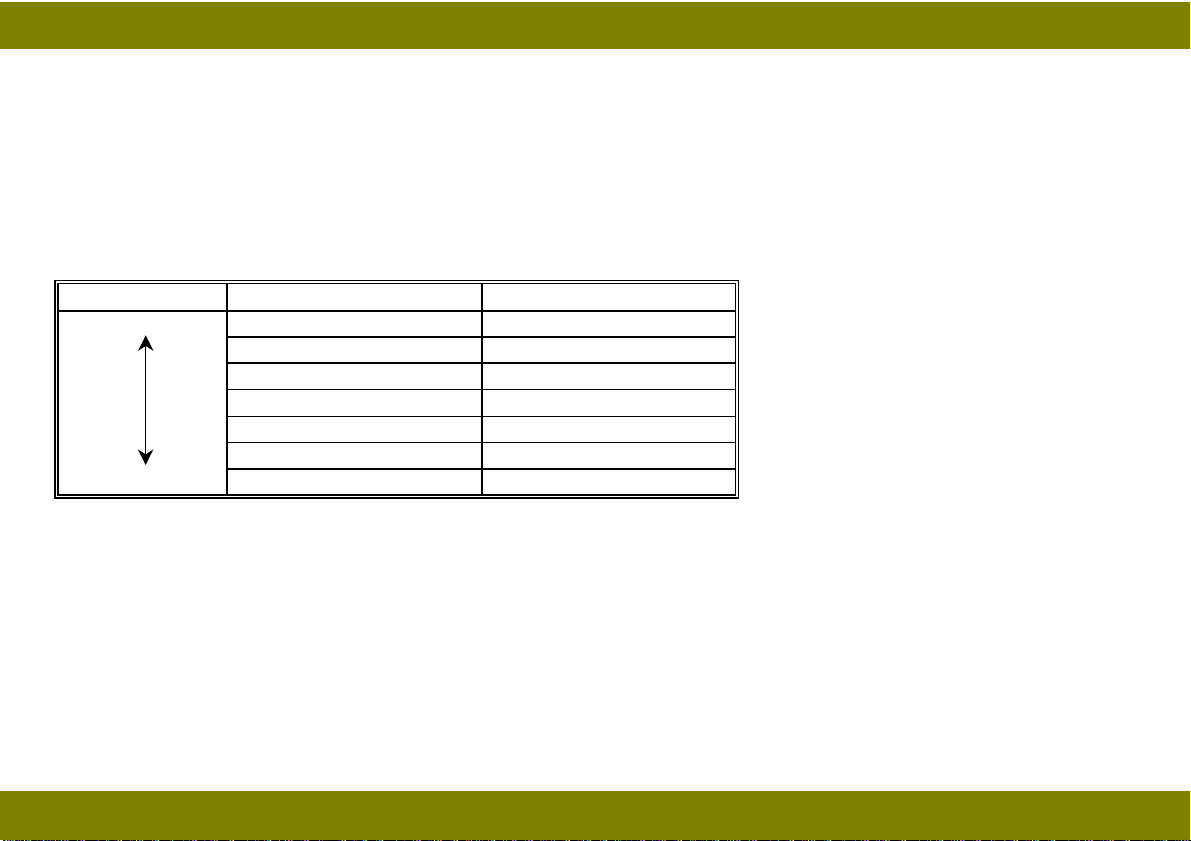
SP30: Exhaust Fan Speed Setting
SP30 is used to select the exhaust fan speed. SP30 was provided for designers’ evaluation. There is
no need to change the setting in the field.
No. Speed Duty
0 Slow 30 %
1
2
3
4
5
6
7
8 High 70 %
↓
↓
↓
↓
↓
↓
↓
35 %
40 %
45 %
50 %
55 %
60 %
65 %
81
Page 85

April 8, 1998 PROGRAM MODES
SP34: Image Density Adjustment (UP1)
SP34 can adjust the copy image density. Both the development bias and the exposure lamp may be
changed. To make a copy in this mode after adjusting, press the Start key.
No. Settings Development
Bias Change
0Normal 0 0
1 Light -40 V 0
2 Dark +40 V 0
3 Lighter -40 V +3 steps
4 Darker +40 V -3 steps
5 Lightest -40 V +7 steps
6 Darkest +40 V -7 steps
Exposure Lamp
Change
1 step = 0.5 V (120 V machines) or 1.0 V (230 V machines)
82
Page 86

April 8, 1998 PROGRAM MODES
SP35: Coarse Image Density Adjustment at Darker Setting Position (UP2)
SP35 adjusts the copy image density at the Darker setting position on the operation panel by
changing the exposure lamp voltage. To make a copy in this mode after adjusting, press the Start
key.
No. Settings Exposure Lamp Change
0 Normal -6 steps
1 Darker -8 steps
2 Darkest -10 steps
1 step = 0.5 V (120 V machines) or 1.0 V (230 V machines)
SP36: Coarse Image Density Adjustment at Lighter Setting Position (UP3)
SP36 adjusts the copy image density at the Lighter setting position on the operation panel by
changing the development bias voltage. To make a copy in this mode after adjusting, press the Start
key.
No. Settings Development Bias Change
0 Normal -40 V
1 Lighter -80 V
2 Lightest -120 V
83
Page 87

April 8, 1998 PROGRAM MODES
SP38: Fine Image Density Adjustment at Darker Setting Position
SP38 adjusts the copy image density at the Darker setting position on the operation panel by
changing the exposure lamp voltage. To make a copy in this mode after adjusting, press the Start
key.
No. Settings Exposure Lamp Change
0 Darkest -3 steps
1 Darker -2 steps
2 Dark -1 step
3Normal 0
4 Light +1 step
5 Lighter +2 steps
6 Lightest +3 steps
1 step = 0.5 V (120 V machines) or 1.0 V (230 V machines)
84
Page 88

April 8, 1998 PROGRAM MODES
SP39: Fine Image Density Adjustment at Lighter Setting Position
SP39 adjusts the copy image density at the Lighter setting position on the operation panel by
changing the exposure lamp voltage. To make a copy in this mode after adjusting, press the Start
key.
No. Settings Exposure Lamp Change
0 Darkest -3 steps
1 Darker -2 steps
2 Dark -1 step
3Normal 0
4 Light +1 step
5 Lighter +2 steps
6 Lightest +3 steps
1 step = 0.5 V (120 V machines) or 1.0 V (230 V machines)
SP41: Lead Edge Erase Margin Adjustment
SP41 adjusts the lead edge erase margin. The lead edge erase margin can be adjusted by 0.5
millimeters per step (-4.0 mm to +3.5 mm). To make a copy in this mode after adjusting, press the
Start key. See “Replacement and Adjustment — Copy Quality adjustment” for details.
Default setting: 8
85
Page 89

April 8, 1998 PROGRAM MODES
SP42: Registration Adjustment
SP42 adjusts image to paper registration. Registration can be adjusted by 0.5 mm per step (-4.0 mm
to +3.5 mm). To make a copy in this mode after adjusting, press the Start key. See “Replacement
and Adjustment — Copy Quality adjustment” for details.
Default setting: 8
SP43: Vertical Magnification Adjustment
SP43 adjusts magnification in the paper travel direction by changing the scanner speed.
Magnification can be adjusted by 0.2% per step (-3.2% to +3.0%). To make a copy in this mode after
adjusting, press the Start key. See “Replacement and Adjustment — Copy Quality adjustment” for
details.
Default setting: 16
SP44: Horizontal Magnification Adjustment (A227 copier only)
SP44 adjusts magnification perpendicular to the direction of paper travel by changing the home
position of the lens and mirrors. The magnification can be adjusted by 0.2% per step (-3.2% to
+3.0%). See “Replacement and Adjustment — Copy Quality adjustment” for details.
Default setting: 16
86
Page 90

April 8, 1998 PROGRAM MODES
SP48: Light Intensity Adjustment
SP48 adjusts the exposure lamp voltage. To make a copy in this mode after adjusting, press the
Start key.
No. Lamp Voltage (V)
120 V (NA) Version 230 V (EU) Version
100 50.0 100
101 50.5 101
102 51.0 102
↓↓ ↓
120
↓↓ ↓
128 64.0
↓↓ ↓
180 90.0 180
↓↓
193 96.5 --194 97.0 ---
=
↓
sequence continues at 0.5 volt/step for 115 V machines and 1.0 volt/step for 230 V machines.
60.0
120
128
---
Do this adjustment whenever the optics are cleaned or VL correction counter is cleared (SP95). After
doing this adjustment, adjust the ADS reference voltage using SP56. See “Replacement and
Adjustment — Copy Quality adjustment” for details.
87
Page 91

April 8, 1998 PROGRAM MODES
SP49: Fusing Temperature Adjustment
SP49 adjusts the control temperature of the hot roller during coping. The fusing temperature can be
adjusted between 195°C and 205°C in 1°C steps. The fusing temperature can be calculated from the
displayed value by adding 15 (i.e. 180 = 195°C).
Default setting: 185 (200
°C)
SP51: Exposure Lamp Voltage Display
SP51 displays the current exposure lamp voltage. For 120 V machines, the actual applied voltage
equals to half of the displayed voltage. The exposure lamp turns on for 10 seconds when this mode
is selected.
The Image Density Indicators are used to display the hundreds digit.
NOTE:
Do not repeat more than 5 times to avoid overheating the optics cavity.
SP52: Fusing Temperature Display
This mode is performed to display the fusing temperature detected by the fusing thermistor. Press
the Start key to monitor the temperature during the normal copy cycle. The Image Density Indicators
are used to display the hundreds digit.
88
Page 92

April 8, 1998 PROGRAM MODES
SP55: ADS Reference Voltage Display
SP55 displays the ADS reference voltage adjusted by SP56. The number to two decimal places is
displayed in the counter. The Image Density Indicators are used to display the unit digit as shown
below.
= "1"
For example:
= "2"
= "3"
+
Copy Counter
= "2.53"
89
Page 93

April 8, 1998 PROGRAM MODES
SP56: ADS Reference Voltage Adjustment
SP56 is used to adjust the ADS reference voltage using VR100 on the main control board. The
number to two decimal places of ADS sensor output is displayed in the counter. The Image Density
Indicators are used to display the unit digit. After 10 seconds, the output is stored as the ADS
reference voltage. The voltage is displayed as shown in the SP55 example.
The adjustment standard voltage is 2.5 ± 0.2 volts. See “Replacement and Adjustment — Copy
Quality adjustment” for details.
SP57: ADS Output Voltage Display
SP57 displays the ADS output voltage.
Press the Start key to monitor the output voltage during the normal copy cycle. The number to two
decimal places is displayed in the counter. The Manual Image Density Indicators are used to display
the unit digit. The voltage is displayed as shown in the SP55 example.
When in SP57 mode, the machine makes copies in the ADS mode.
90
Page 94

April 8, 1998 PROGRAM MODES
SP58: Development Bias Voltage Display
SP58 displays the development bias voltage.
Press the Start key to monitor the development bias voltage during the normal copy cycle. The
Manual Image Density Indicators are used to display the hundreds digit.
When in SP58 mode, the machine makes copies in the ADS mode.
SP59: Optics Temperature Display (SP59)
SP59 displays the optics temperature detected by the optics thermistor.
Press the Start key to monitor the optics temperature during the normal copy cycle.
SP60: Drum Potential Measurement (With Paper)
Factory use only using special tools.
SP61: Drum Potential Measurement (Without Paper)
Factory use only using special tools.
91
Page 95

April 8, 1998 PROGRAM MODES
SP62: VL Switch Setting (UP32)
SP62 sets the effective level for the VL switch inside of the machine.
SP62 Settings Special UP Mode Exposure Lamp Voltage Change
UP32 SW Position 0 SW Position 1 SW Position 2
0 0 0 +10 steps +20 steps
1 1 0 +5 steps +10 steps
2 2 0 +15 steps +30 steps
3 3 0 +20 steps +40 steps
1 step = 0.5 V (120 V machines) or 1.0 V (230 V machines)
92
Page 96

April 8, 1998 PROGRAM MODES
SP63: VL Correction Interval (UP31)
SP63 sets the interval for VL correction. The exposure lamp voltage (SP48) is increased by 1 step at
the set copy count interval. Based on copy count, VL correction is performed at the intervals shown in
the below table.
SP63 Settings Exposure Lamp Voltage change Special UP Mode
UP31
0 +1 step/4000 copies 0
1 +1 step/3000 copies 1
2 +1 step/2500 copies 2
3 +1 step/2000 copies 3
4 +1 step/1500 copies 4
5 +1 step/1000 copies 5
6 +1 step/500 copies --7 +1 step/250 copies --8 No Correction ---
1 step = 0.5 V (120 V machines) or 1.0 V (230 V machines)
93
Page 97

April 8, 1998 PROGRAM MODES
SP64: Photo Mode Compensation Setting (UP4)
SP64 sets the image density level for photo mode.
The development bias and the exposure lamp voltage are compensated according to the setting of
this mode.
No. Settings Development Bias Exposure Lamp Change
0 Lightest -270 V +4 steps
1 Lighter -270 V +2 steps
2 Light -270 V ---
3 Normal -230 V ---
4 Dark -210 V --5 Darker -190 V ---
1 step = 0.5 V (120 V machines) or 1.0 V (230 V machines)
SP66: OPC Counter Clear
Use SP66 to clear the OPC counter after replacing the new OPC drum.
Set SP66 to 1, and then press the Image Density key and Start key together.
94
Page 98

April 8, 1998 PROGRAM MODES
SP69: OPC Counter Display (UP30)
SP69 shows the total number of copies made by the OPC
Image D ensity Indicator
Copy Counter
drum installed in the machine.
Two digits at a time of the six digits for the OPC counter
are displayed on the copy counter. To view the next two
digits, press the Start key.
Lighter Image Density Indicator is lit when the sixth and
fifth digits are displayed.
Auto Image Density Indicator is lit when the fourth and third
digits are displayed.
Darker Image Density Indicator is lit when the second and
first digits are displayed.
The example to the right shows the counter display when
the copy count is 25148.
SP70: VL Correction Display
SP70 displays the VL correction counter. This counter value is used for VL correction (SP63).
95
Page 99

April 8, 1998 PROGRAM MODES
Two digits at a time of the six digits f or the counter are displayed on the copy counter. To view the
next two digits, press the Start key.
Lighter Image Density Indicator is lit when the sixth and fifth digits are displayed.
Auto Image Density Indicator is lit when the fourth and third digits are displayed.
Darker Image Density Indicator is lit when the second and first digits are displayed.
This counter is displayed as shown in the SP69 example.
SP77: Auto Shut Off (Energy Star) Selection (UP34)
SP77 selects the “Automatic Shut Off” mode.
The machine automatically shuts itself off at the auto shut off time selected by SP14.
No. Settings
0 Enabled
1 Disabled
SP81: Factory Initialization
Factory use only using special tools.
96
Page 100

April 8, 1998 PROGRAM MODES
SP82: Data Communication
Factory use only using special tolls.
SP88: Total Copy Counter Display (UP8)
SP88 displays the total copy counter. (This machine uses a software counter rather than a
mechanical counter to count total copies.)
Two digits at a time of the six digits f o r the counter are displayed on the copy counter. To view the
next two digits, press the Start key.
Lighter Image Density Indicator is lit when the sixth and fifth digits are displayed.
Auto Image Density Indicator is lit when the fourth and third digits are displayed.
Darker Image Density Indicator is lit when the second and first digits are displayed.
This counter is displayed as shown in the SP69 example.
SP90: Factory Data and Counter Clear
Factory use only using special tools.
SP91: Optics Cooling Fan Operation
Factory use only using special tools.
97
 Loading...