

Page 1

RICOHFAX75
Sixty page memory,
wide document trans-
mission range, and
programmability for
versatile performance
IMl(m)lIl
Page 2

Page 3
This equipment generates and uses radio frequency energy and If not Installed and used
properly, that Is, In strict accordance with the manufacturer’s Instructions, may cause interference to radio and television reception. It has been type tested and found to comply with
the Ilmlts for a Class B computing device in accordance with the specifications In Subpart J
of Part 15 of FCC Rules, which are designed to provide reasonable protection against such
Interference In a residential installation If this equipment does cause Interference to radio or
television reception, which can be determined by turning the equipment off and on, the user
IS encouraged to try to correct the Interference by one or more of the followlng measures
Reorient the receiving antenna
Relocate the computer with respect to the recewer
Move the computer away from the receiver
Plug the computer Into a different outlet so that computer and recewer are on different
branch clrcults If necessary, the user should consult the dealer or an experienced radio television technician for additional suggestions The user may find the followlng booklet prepared by the Federal Communications Commission helpful:
“How to Identify and Resolve Radio-TV Interference Problems” This booklet IS available
from the U S Government Prlntlng Office, Washington, DC20402, Stock No
004-000 -00345-4
Page 4
IMPORTANT SAFETY INSTRUCTIONS
1. Read ail of these instructions.
2. Save these instructions for later use.
3. Follow all warnings and instructions marked on the product.
4. Unplug this product from the wall outlet before cleaning. Do not use liquid cleaners or
aerosol cleaners. Use a damp cloth for cleaning
5. Do not use this product near water
6. Do not place this product on an unstable cart, stand, or table. The product may fall,
causing serious damage to the product.
7. Slots and openings in the cabinet and the back or bottom are provided for ventilation;
to ensure reliable operation of the product and to protect it from overheating, these
openings must not be blocked or covered. The openings should never be blocked by
placing the product on a bed, sofa, rug, or other similar surface. This product should
never be placed near or over a radiator or heat register. This product should not be
placed in a built-in installation unless proper ventilation is provided.
8. This product should be operated from the type of power source indicated on the mark-
ing label. If you are not sure of the type of power available, consult your dealer or local
power company
9. This product is equipped with a 3-wire grounding type plug, a plug having a third
(grounding) pin. This plug will only fit into a grounding-type power outlet. This is a
safety feature. If you are unable to insert the plug into the outlet, contact your electrician
to replace your obsolete outlet. Do not defeat the purpose of the grounding-type plug
10. Do not allow anything to rest on the power cord, Do not locate this product where persons will walk on the cord.
11. If an extension cord is used with this product, make sure that the total of the ampere
ratings on the products plugged into the extension cord do not exceed the extension
cord ampere rating. Also, make sure that the total of all products plugged into the wall
outlet does not exceed 15 amperes.
12. Never push objects of any kind into this product through cabinet slots as they may
touch dangerous voltage points or short out parts that could result In a risk of fire or
electric shock. Never spill liquid of any kind on the product.
13. Do not attempt to service this product yourself, as opening or removing covers may
expose you to dangerous voltage points or other risks. Refer all servicing to qualified
service personnel.
14. Unplug this product from the wall outlet and refer servicing to qualified service personnel under the following conditions:
A. When the power cord or plug is damaged or frayed.
B. If liquid has been spilled into the product.
C. If the product has been exposed to rain or water.
D. If the product does not operate normally when the operating instructions are fol-
lowed.
Adjust only those controls that are covered by the operating instructions since
improper adjustment of other controls may result in damage and will often require
extensive work by a qualified technician to restore the product to normal operation.
E. If the product has been dropped or the cabinet has been damaged.
F, If the product exhibits a distinct change in performance, indicating a need for ser-
vice.
Page 5

Code
No.
50
51
52
53
54
55
56
60
61
62
63
64
65
66
67
70
71
72
73
74
75
76
77
80
81
82
FUNCTION LIST
Function
1
Confidential Transmission
2
Send Later
Transfer Request
3
4
Polling Transmission/ Polhng Reception
Clock Adjustment
Communicated Page Counter Display
Total Scan and Print Counter Display
Batch-number Enabling
Department Code Enabling
Speaker Volume Adjustment
Transmission Report Enabling
Quick Dial Programming
Group Programming
Polling ID Code Programming
RTI Programming
TTI Programming
CSI Programming
Polling File Clearance
Memory File Clearance
TCR Output
Telephone List Output
Polling File List Output
Program List Output
SAF File List Output
File Output
Confidential File Output
Multicopymg
Own Telephone Number Programming
Telephone Line Type Selection
TTI Enabllng Disabling
ECM Enabling Disabling
83
Password Programming
89
Page 6

Page 7
CONTENTS
1 PRECAUTIONS
1- 1 Power and Grounding
1- 2 Cold Weather Power-up
1- 3 Thunderstorms
1- 4 Copy Paper
1- 5 Stamp Ink
2 COMPONENT GUIDE
3. INSTALLATION
3- 1 Unpacking
3- 2 List of Contents
3- 3 Installation Requirements
3- 4 Installation Procedure
4 OPERATION PANEL
5 INITIAL START-UP
6 RECOMMENDED TYPES OF DOCUMENT
7 ROUTINE OPERATION
7- 1 Transmission
7- 2 Reception
7- 3 Ringing Telephones and Buzzers
7- 4 Making Telephone Calls (On-hook Dialing)
7- 5 International Dialing
7- 6 Replaclng Paper
7- 7 Daily Care
7- 8 Refilling the Stamp
—
Basic Transmission
Transmlsslon using the Memory
Automatic Reception
Manual Reception
Confidential File
Recewe File (Substitute Reception)
Ring
Single
Continuous Ringing
11111-
2-
3333-
4-
5-
6-
7-
7-10
7-12
7-12
7-13
7-14
7-15
7-16
1
2
2
3
3
1
1
2
3
4
1
1
1
1
8 SPECIAL FEATURES
8- 1 Confidential Transmission
8- 2 Send Later Transmission
8- 3 Transfer Request
8- 4 Polling
Polling Reception
Polllng Transmission
Turnaround Polllng
8- 1
8- 3
8- 5
,.,
8- 8
8- 8
8-11
8-13
1
Page 8
Voice Request . . . . . . . . . . . . . . . . . . . . . . . . . . . . . . . . . . . . . . . . . . . . . . . . . . . . . . .
8- 5
Alternative Destination, . . . . . . . . . . . . . . . . . . . . . . . . . . . . . . . . . . . . . . . . . . . . . .
8- 6
immediate Radial . . . . . . . . . . . . . . . . . . . . . . . . . . . . . . . . . . . . . . . . .
8- 7
Protection Against Wrong Connections . . . . . . . . . . . . . . . . . . . . . . . . . . . .
8- 8
8- 9
Using a Keystroke Program . . . . . . . . . . . . . . . . . . . . . . . . . . . . . . . . . . . . . . . . .
Monitor Speaker . . . . . . . . . . . . . . . . . . . . . . . . . . . . . . . . . . . . . . . . . . . . . . . . . . . . .
8-10
8-11
Using the Machine asa Copier . . . . . . . . . . . . . . . . . . . . . . . . . . . . . . .
8-12
GI Mode . . . . . . . . . . . . . . . . . . . . . . . . . . . . . . . . . . . . . . . . . . . . . . . . . . . . . .
8-13
Document Stamping . . . . . . . . . . . . . . . . . . . . . . . . . . . . . . . . . . . . . . . . .
9. FUNCTIONS AND PROGRAMMING
9- 1
Clock Adjustment . . . . . . . . . . . . . . . . . . . . . . . . . . . . . . . . . . . . . . . . . . . . 9- 1
9- 2
Communicated Page Counter Display . . . . . . . . . . . . . . . . . . . . . . . . . . . . . . . ,., 9-2
9- 3
Total Scan and Print Counter Display . . . . . . . . . . . . . . . . . . . . . . . . . . . . . . . . 9-2
9- 4
Batch-number Enabling . . . . . . . . . . . . . . . . . . . . . . . . . . . . . . . . . . . . . . . . . . . . . . 9-3
9- 5
Department Code Enabling.. . . . . . . . . . . . . . . . . . . . . . . . . . . . . . . . . . . . . . . . . . 9-4
9- 6
Speaker and Handset VolumeAdjustment . . . . . . . . . . . . . . . . . . . . . . . . . . . . . . 9- 5
9- 7
Transmission Report Enabling.. . . . . . . . . . . . . . . . . . . . . . . . . . . . . . . . . . . . . . . . 9-6
9- 8
Programming Quick Dial and Speed Dial . . . . . . . . . . . . . . . . . . . . . . . . . . . . . . . 9- 7
Programming aNew Codeor Key . . . . . . . . . . . . . . . . . . . . . . . . . . . . . . . . . . . 9- 7
Changing or Deleting aCode or Key . . . . . . . . . . . . . . . . . . . . . . . . . . . . . . . 9-9
9- 9
Programming Groups . . . . . . . . . . . . . . . . . . . . . . . . . . . . . . . . . . . . . . . . . . . . . . . 9-12
9-1o
Setting the Polling lDCode . . . . . . . . . . . . . . . . . . . . . . . . . . . . . . . . . . . . . . . . . . . 9-14
9-11
Entering the RTl, TTl, and Cal.... . . . . . . . . . . . . . . . . . . . . . . . . . . . . . . . . . . . . . 9-15
9-12
Clearing Polling Files . . . . . . . . . . . . . . . . . . . . . . . . . . . . . . . . . . . . . . . . . . . . . . . . . 9-17
9-13
Clearing Memory Files . . . . . . . . . . . . . . . . . . . . . . . . . . . . . . . . . . . . . . . . . . . . . . . . 9-18
9-14
Programming Your Fax Telephone Number . . . . . . . . . . . . . . . . . . . . . . . . . . . 9-19
9-15
Programming theTelephone Line Type . . . . . . . . . . . . . . . . . . . . . . . . . . . . . . . . 9-20
9-16
Disabling the TT1 . . . . . . . . . . . . . . . . . . . . . . . . . . . . . . . . . . . . . . . . . . . . . . . . . . . . 9-21
9-17
Enabling and Disabling ECM . . . . . . . . . . . . . . . . . . . . . . . . . . . . . . . . . . . . . . . . . 9-22
9-18
Automatic Voice Message (AIM) . . . . . . . . . . . . . . . . . . . . . . . . . . . . . . . . . . . . . 9-23
9-19
Programming the Password . . . . . . . . . . . . . . . . . . . . . . . . . . . . . . . . . . . . . . . . . 9-25
9-20
Storing Keystroke Programs . . . . . . . . . . . . . . . . . . . . . . . . . . . . . . . . . . . . . . . . . 9-26
9-21
Printing the Contents ofa Memory File . . . . . . . . . . . . . . . . . . . . . . . . . . . . . . . . . 9-27
8-14
8-15
8-17
8-17
8-18
8-18
8-19
8-20
8-20
10. REPORTS AND LISTS
10-l Automatic Reports...,.. . . . . . . . . . . . . . . . . . . . . . . . . . . . . . . . . . . . . . . . . . . . . 10- 1
TAR . . . . . . . . . . . . . . . . . . . . . . . . . . . . . . . . . . . . . . . . . . . . . . . . . . . . . . . . . . . . . . 10- 1
Error Report . . . . . . . . . . . . . . . . . . . . . . . . . . . . . . . . . . . . . . . . . . . . . . . . . . . . . . 10-2
Transmission Report . . . . . . . . . . . . . . . . . . . . . . . . . . . . . . . . . . . . . . . . . . . . . . . 10-2
Transfer Result Report . . . . . . . . . . . . . . . . . . . . . . . . . . . . . . . . . . . . . . . . . . . . . 10-3
Polling File List . . . . . . . . . . . . . . . . . . . . . . . . . . . . . . . . . . . . . . . . . . . . . . . 10-4
New File Report . . . . . . . . . . . . . . . . . . . . . . . . . . . . . . . . . . . . . . . . . . . . . . . . . 10-5
Memory Transmission Report. . . . . . . . . . . . . . . . . . . . . . . . . . . . . . . . . . . . . . 10-5
Power Failure Report . . . . . . . . . . . . . . . . . . . . . . . . . . . . . . . . . . . . . . . . . . . . . . 10-5
2
Page 9
10-2 User-initiated Reports .,
TCR. .“.
Telephone List
Polling File List
Program List
SAF File List
10- 6
10- 6
10- 6
10- 9
1o-1o
10-11
11 TROUBLESHOOTING
11-1 Misfeeds
Scanner
Printer
11-2 Line Failure
11-3 Operating Difficulties
11-4 Error Codes
12. SPECIFICATIONS
13. GLOSSARY
Notice to Users
111111111111-
12-
13-
1
1
2
3
3
4
1
1
Page 10

Page 11

NOTICE TO USERS
USA
FCC Notice To Users:
1
The followlng information shall be provided to the telephone company, upon request of
the telephone company.
a) The FCC registration number
b) the Ringer Equivalence number.
2
These units may not be used on party lines or coin telephones
3
The telco has the right to make changes in their network which may affect the operation
of your unit, provided adequate notice is given to you in advance to permit continued correct operation
4
In the event of operation problems, disconnect your unit by removing the modular plug
from the telco modular jack. If your regular phone still works correctly, your machine has
a problem and should be returned for repairs (In or out of warranty). If upon disconnection
of your machine there is still a problem on your line, notify the telco that they have a
problem and request prompt repair service at no cost to the user.
5
The user may not under any circumstances (in or out warranty) attempt any service or repairs on the machine It must be returned to the factory or an authorized service agency
for all repairs. Call 1-800 -FASTFIX for information on obtaining repairs
●
The FCC registration number and ringer equivalence number can be found on a label,
located on the back of the machine,
CANADA
The Canadian Department of Communications label identifies certified equipment This certification means that the equipment meets certain telecommunications network protective,
operational, and safety requirements. The department does not guarantee the equipment
will operate to the user’s satisfaction.
Before Installing this equipment, users should ensure that it is permissible to be connected
to the facilities of the local telecommunications company. The equipment must also be in-
stalled using an approved method of connection. In some cases, the company’s inside
wiring associated with a single line individual service may be extended by means of a certified jack-plug-cord ensemble (telephone extension cord). The customer should be aware
that compliance with the above conditions may not prevent degradation of service In some
situations. Existing telecommunications company requirements do not permit their equip-
ment to be connected to customer-provided jacks except where specified by individual telecommunications company tariffs.
Page 12
Repairs to certified equipment should be made by an authorized Canadian maintenance
facility designated by the supplier. Any repairs or alterations made by the user to this equipment, or equipment malfunctions, may give the telecommunications company cause to request the user to disconnect the equipment.
Users should ensure for their own protection that the electrical ground connections of the
power utility, telephone lines and internal metallic water pipe system, if present, are connected together. This precaution may be particularly important in rural areas.
Caution: Users should not attempt to make such connections themselves, but should
The standard connecting arrangement code for this equipment is:
CA1 1A or CA45A
The Load number (LN) assigned to each terminal device denotes the percentage of the total
load to be connected to a telephone loop which is used by the device to prevent overloading.
The termination on a loop may consist of any combination of devices subject only to the requirement that the total of the load numbers of all the devices does not exceed 100.
contact the appropriate electric inspection authority, or electrician, as appropriate.
2
Page 13
NOTICE TO USERS
USA
FCC Notice To Users:
1
The following information shall be provided to the telephone company, upon request of
the telephone company:
a) The FCC registration number.
b) the Ringer Equivalence number.
2
These units may not be used on party lines or coin telephones,
3
The telco has the right to make changes in their network which may affect the operation
of your unit, provided adequate notice is given to you in advance to permit continued correct operation,
4
In the event of operation problems, disconnect your unit by removing the modular plug
from the telco modular jack. If your regular phone still works correctly, your machine has
a problem and should be returned for repairs (in or out of warranty). If upon disconnection
of your machine there is still a problem on your line, notify the telco that they have a
problem and request prompt repair service at no cost to the user.
5
The user may not under any circumstances (in or out warranty) attempt any service or repairs on the machine, It must be returned to the factory or an authorized service agency
for all repairs, Call 1 -800 -FASTFIX for information on obtaining repairs,
●
The FCC registration number and ringer equivalence number can be found on a label,
located on the back of the machine. -
CANADA
The Canadian Department of Communications label identifies certified equipment This certification means that the equipment meets certain telecommunications network protective,
operational, and safety requirements. The department does not guarantee the equipment
will operate to the user’s satisfaction.
Before Installing this equipment, users should ensure that it is permissible to be connected
to the facilities of the local telecommunications company. The equipment must also be installed using an approved method of connection. In some cases, the company’s inside
wiring associated with a single line individual service may be extended by means of a certi-
fied jack-plug-cord ensemble (telephone extension cord). The customer should be aware
that compliance with the above conditions may not prevent degradation of service in some
situations. Existing telecommunications company requirements do not permit their equipment to be connected to customer-provided jacks except where specified by individual telecommunications company tariffs.
Page 14
Repairs to certified equipment should be made by an authorized Canadian maintenance
facility designated by the supplier. Any repairs or alterations made by the user to this equip-
ment, or equipment malfunctions, may give the telecommunications company cause to re-
quest the user to disconnect the equipment.
Users should ensure for their own protection that the electrical ground connections of the
power utility, telephone lines and internal metallic water pipe system, if present, are connect-
ed together. This precaution may be particularly important in rural areas.
Caution:
Users should not attempt to make such connections themselves, but should
contact the appropriate electric inspection authority, or electrician, as appropriate.
The standard connecting arrangement code for this equipment is:
CA1 1A or CA45A
The Load number (LN) assigned to each terminal device denotes the percentage of the total
load to be connected to a telephone loop which is used by the device to prevent overloading.
The termination on a loop may consist of any combination of devices subject only to the requirement that the total of the load numbers of all the devices does not exceed 100.
2
Page 15
1. PRECAUTIONS
WARNING
Do not attempt any maintenance or troubleshooting
manual
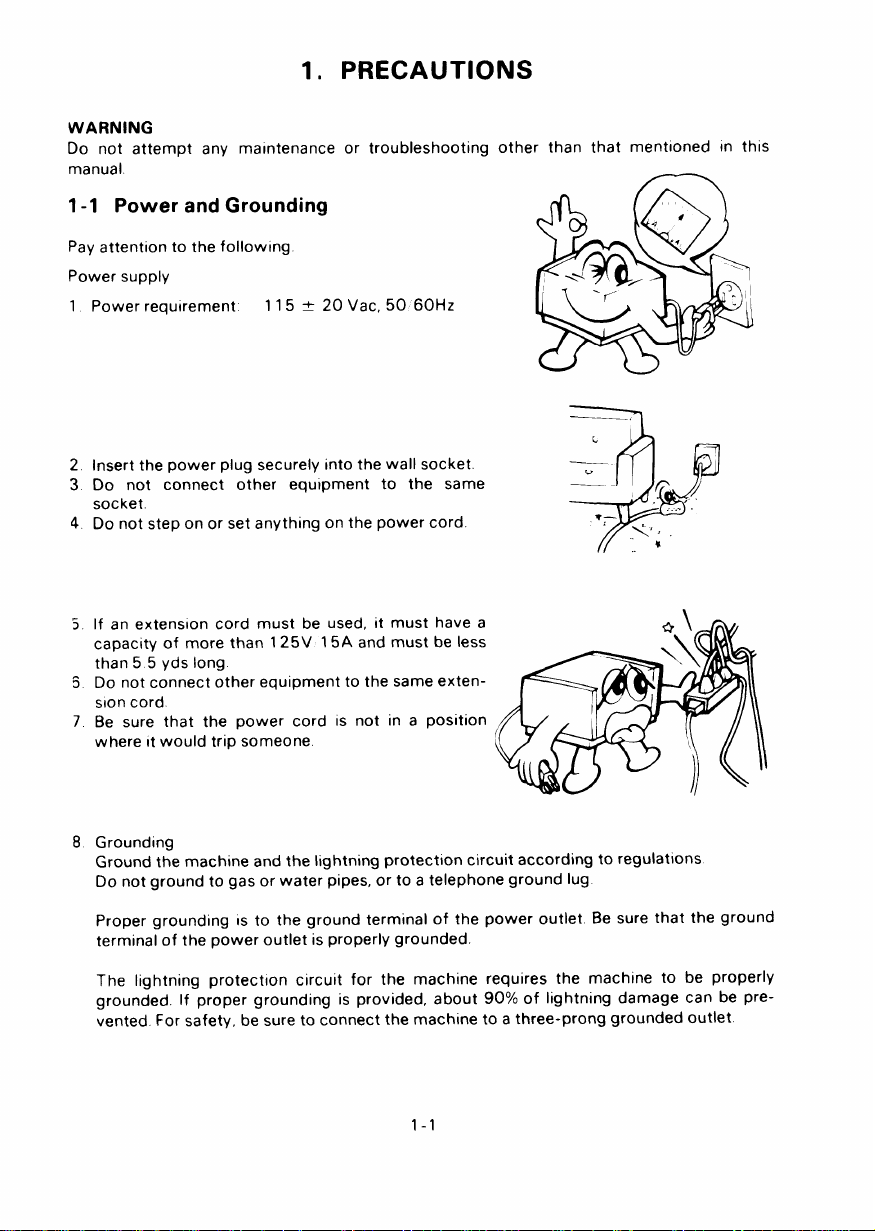
1-1 Power and Grounding
Pay attention to the followlng
Power supply
1 Power requirement
2 Insert the power plug securely Into the wall socket.
3 Do not connect other equipment to the same
socket
4 Do not step on or set anything on the power cord
5 If an extension cord must be used, it must have a
capacity of more than 125V 15A and must be less
than 55 yds long
3 Do not connect other equipment to the same exten-
sion cord
7 Be sure that the power cord IS not in a position
where It would trip someone
115 t 20 Vat, 50 60Hz
other than that mentioned In this
8 Grounding
Ground the machine and the lightning protection circuit according to regulations
Do not ground to gas or water pipes, or to a telephone ground lug
Proper grounding IS to the ground terminal of the power outlet Be sure that the ground
terminal of the power outlet is properly grounded.
The lightning protection circuit for the machine requires the machine to be properly
grounded If proper grounding is provided, about 90% of lightning damage can be prevented For safety, be sure to connect the machine to a three-prong grounded outlet
1-1
Page 16
.
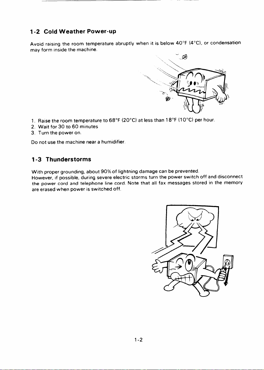
1-2 Cold Weather Power-up
Avoid raising the room temperature abruptly when it is below 40°F (4°C), or condensation
may form inside the machine.
“.@
\
\
Raise the room temperature to 68°F (20°C) at less than 18°F (1 O“C) per hour.
1.
Wait for 30 to 60 minutes
2.
Turn the power on.
3.
Do not use the machine near a humidifier.
1-3 Thunderstorms
With proper grounding, about 90% of lightning damage can be prevented.
However, if possible, during severe electric storms turn the power switch off and disconnect
the power cord and telephone line cord. Note that all fax messages stored in the memory
are erased when power is switched off.
1-2
Page 17
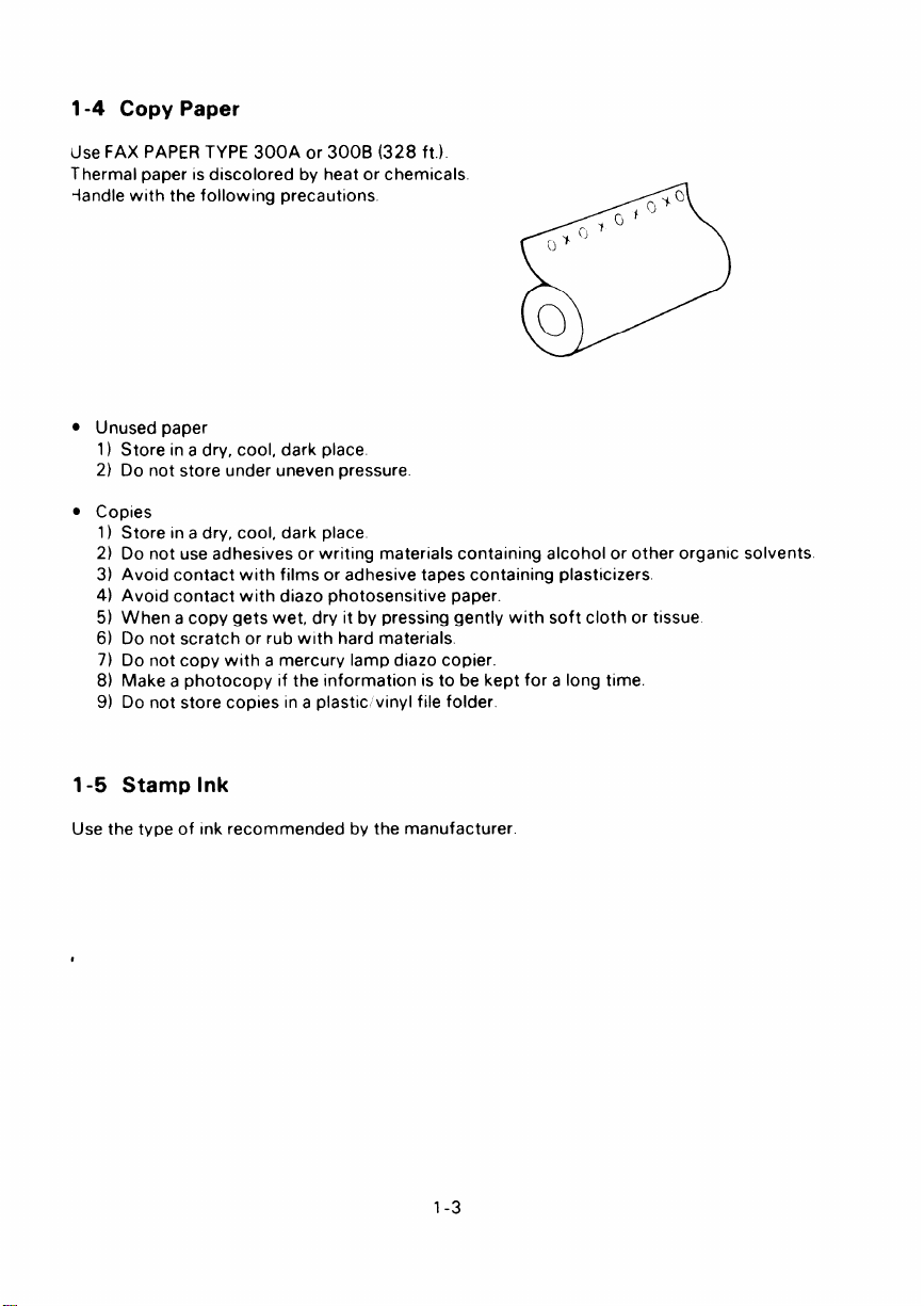
1-4 Copy Paper
Use FAX PAPER TYPE 300A or 300B (328 ft.)
Thermal paper is discolored by heat or chemicals
-landle with the following precautions.
. Unused paper
1) Store in a dry, cool, dark place.
2) Do not store under uneven pressure
● Copies
1) Store In a dry, cool, dark place
2) Do not use adhesives or writing materials containing alcohol or other organic solvents
3) Avoid contact with films or adhesive tapes containing plasticizers
4) Avoid contact with diazo photosensitive paper.
5) When a copy gets wet, dry it by pressing gently with soft cloth or tissue
6) Do not scratch or rub with hard materials.
7) Do not copy with a mercury lamp diazo copier.
8) Make a photocopy If the information is to be kept for a long time
9) Do not store copies in a plastic vinyl file folder.
1-5 Stamp Ink
Use the type of Ink recommended by the manufacturer
1-3
Page 18

I
Page 19
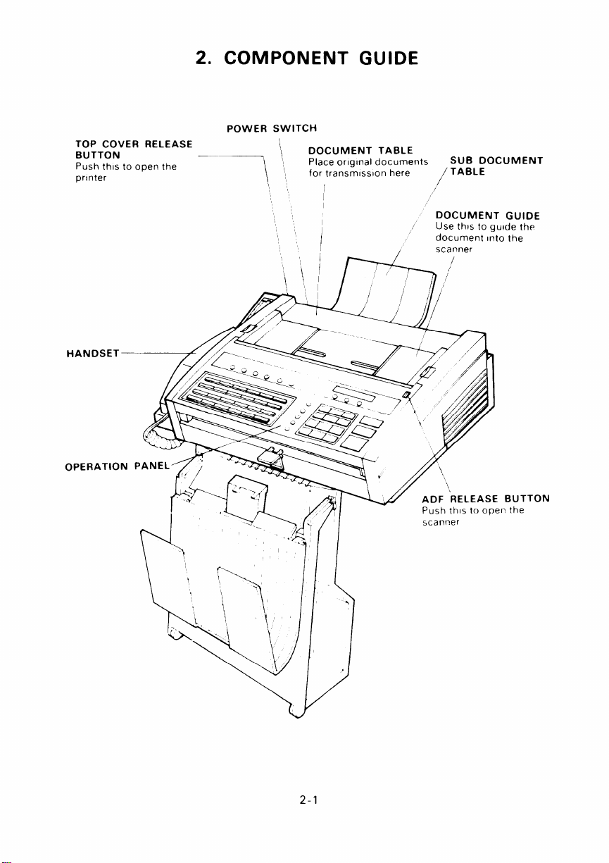
TOP COVER RELEASE
BUTTON
Push this to open the
printer
HANDSET—
OPERATION
2. COMPONENT GUIDE
POWER SWITCH
\
——
\, “
DOCUMENT TABLE
\,
Place orlglnal documents
for transmission here
/
II
1,
/
SUB DOCUMENT
TABLE
/
DOCUMENT GUIDE
Use this to guide the
document Into the
scanner
I
2-1
Push this to open the
BUTTON
scanver
Page 20

Page 21
3. INSTALLATION
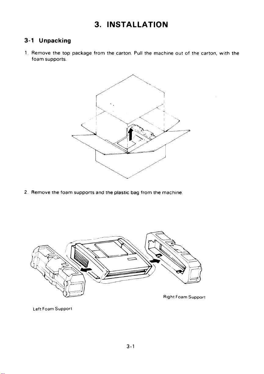
3-1 Unpacking
1 Remove the top package from the carton Pull the machine out of the carton, with the
foam supports.
2 Remove the foam supports and the plastic bag from the machine
Left Foam support
3-1
Page 22
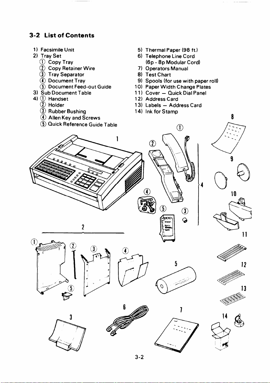
3-2 List of Contents
1) Facsimile Unit
2) Tray Set
@ Copy Tray
@ Copy Retainer Wire
@ Tray Separator
@ Document Tray
@ Document Feed-out Guide
3) Sub Document Table
4)0 Handset
@ Holder
@ Rubber Bushing
@ Allen Key and Screws
@ Quick Reference Guide Table
2
Thermal Paper (98 ft.)
5)
Telephone Line Cord
6)
(6p - 8p Modular Cord)
7)
Operators Manual
8)
Test Chart
9)
Spools (for use with paper roll)
1o)
Paper Width Change Plates
11)
Cover –
12)
Address Card
13)
Labels – Address Card
14)
Ink for Stamp
Quick Dial Panel
0
---
--
-.
0
\
\
c)
8
--
--
-.
--
9
\
Q)
3
‘.,
-
Q
3-2
/’
&
12
/
/-
@
&
7
II
‘ !$
‘4
13
.
Page 23
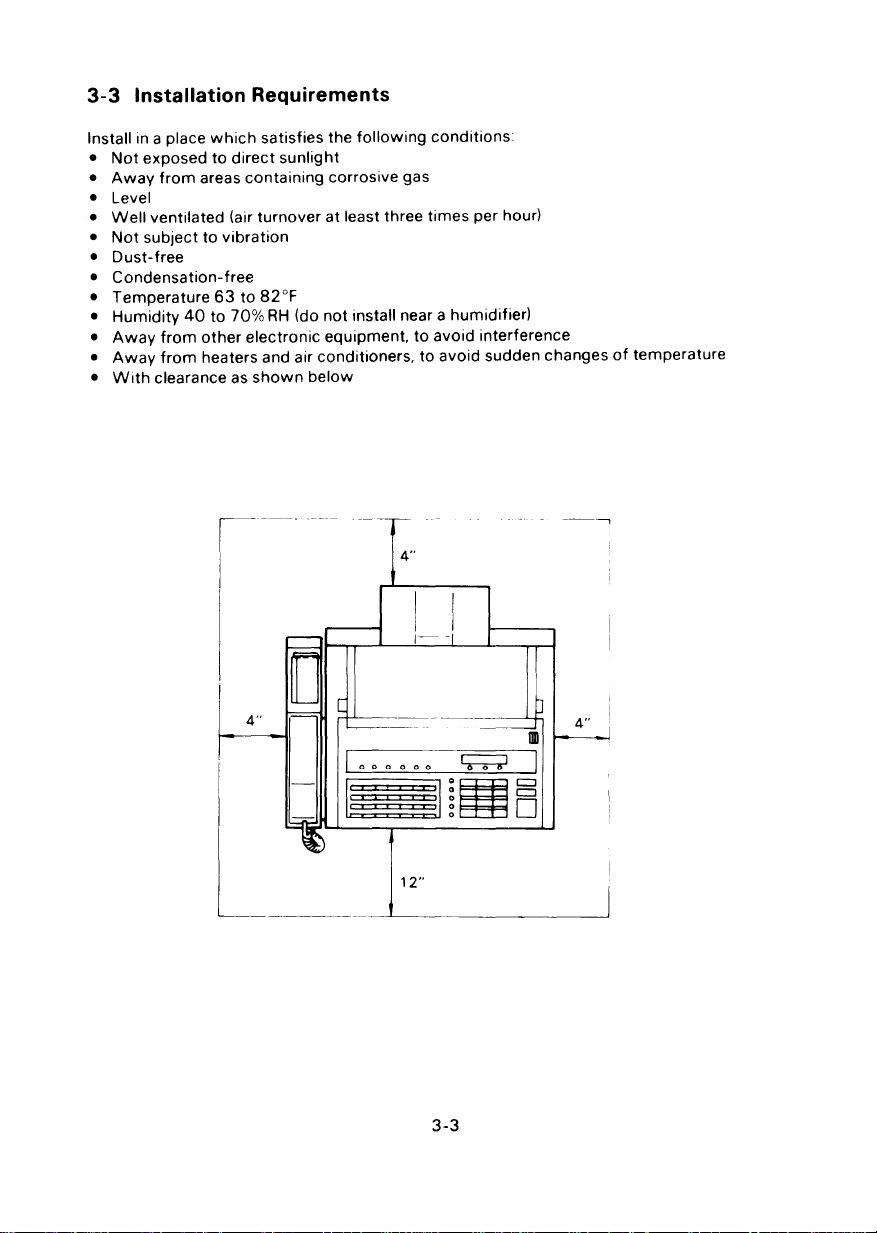
3-3 Installation Requirements
Install In a place which satisfies the following conditions.
●
Not exposed to direct sunlight
●
Away from areas containing corrosive gas
●
Level
●
Well ventilated (air turnover at least three times per hour)
●
Not subject to vibration
●
Dust-free
●
Condensation-free
●
Temperature 63 to 82°F
●
Humidity 40 to 70% RH (do not Install near a humidifier)
●
Away from other electronic equipment, to avoid interference
●
Away from heaters and air conditioners, to avoid sudden changes of temperature
●
With clearance as shown below
—
?==l
—
—
E
000000
I
. ..-L-
-—
4“
I
1’I
I
12“
I
II
,— .,
I I
—
m
0
0
0
0
0
RI”
—
I
+
-i
H
3-3
Page 24
——
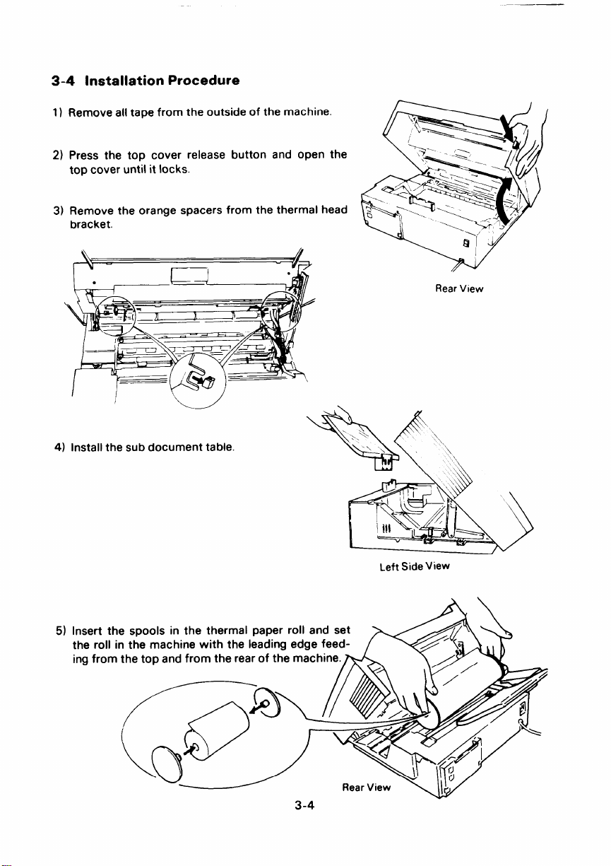
3-4 Installation Procedure
1]
Remove all tape from the outside of the machine.
2)
Press the top cover release button and open the
top cover until it locks.
Remove the orange spacers from the thermal head
3)
bracket.
\
I
●
I
—,
~—=”P
.-!?!?/
Rear View
/
4) Install the sub document table.
5) Insert the
the roll in
ing from t
\
Left Side View
3-4
Page 25
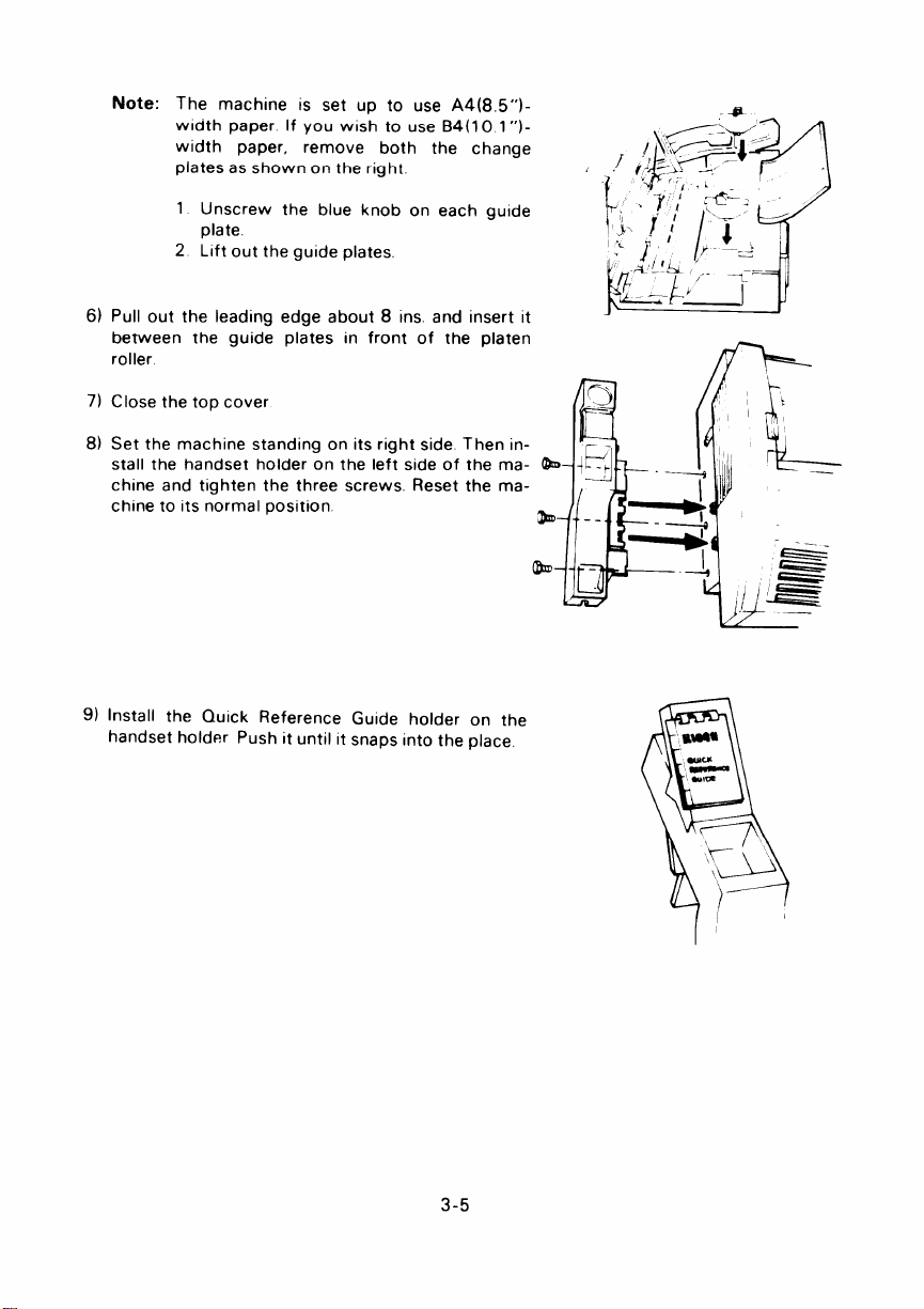
Note:
The machine is set up to use A4(8,5”)width paper If you wish to use B4(1 O 1“)wldth paper,
plates as shown on the right.
1 Unscrew the blue knob on each guide
plate
2 Lift out the guide plates,
Pull out the leading edge about 8 ins. and insert it
6)
between the guide
roller
7)
Close the top cover
Set the machine standing on Its right side
8)
stall the handset holder on the left side of
chine and tighten the three screws. Reset
chine to its normal position
9) Install the Quick Reference Guide holder on the
handset holder Push It until It snaps into the place.
remove both the change
plates In front of the platen
m
~\<&y.:-
.~ &.<”~ ,
i ‘F”-, ?T -
~
7’/’
,J., f; ‘~’
!/
, : ~L!L ,~ --~ ‘
#_ --~.k’-- ~- )
<6-,
fl
3-5
Page 26
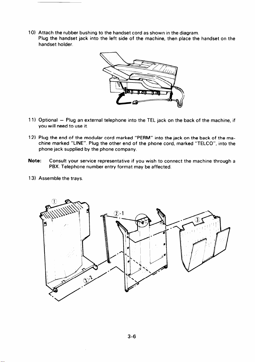
10) Attach the rubber bushing to the handset cord as shown in the diagram.
Plug the handset jack into the left side of the machine, then place the handset on the
handset holder.
11 ) Optional –
you will need to use it.
12) Plug the end of the modular cord marked “PERM” into the jack on the back of the machine marked “LINE”. Plug the other end of the phone cord, marked “TELCO”, into the
phone jack supplied by the phone company.
Note:
13) Assemble the trays,
Plug an external telephone into the TEL jack on the back of the machine, if
Consult your service representative if you wish to connect the machine through a
PBX. Telephone number entry format may be affected.
3-6
Page 27
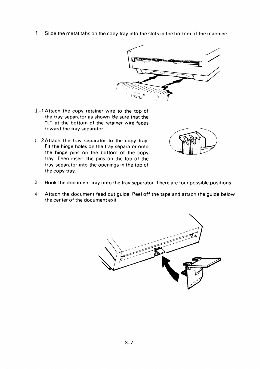
1
Slide the metal tabs on the copy tray Into the slots In the bottom of the machine
Attach the copy retainer wire to the top of
2-1
the tray separator as shown. Be sure that the
“L” at the bottom of the retainer wire faces
toward the tray separator
2 -2 Attach the tray separator to the copy tray
Fit the hinge holes on the tray separator onto
the hinge pins on the bottom of the copy
tray Then Insert the pins on the top of the
tray separator Into the openings in the top of
the copy tray
Hook the document tray onto the tray separator There are four possible positions
3
Attach the document feed out guide Peel off the tape and attach the guide below
4
the center of the document exit
3-7
Page 28
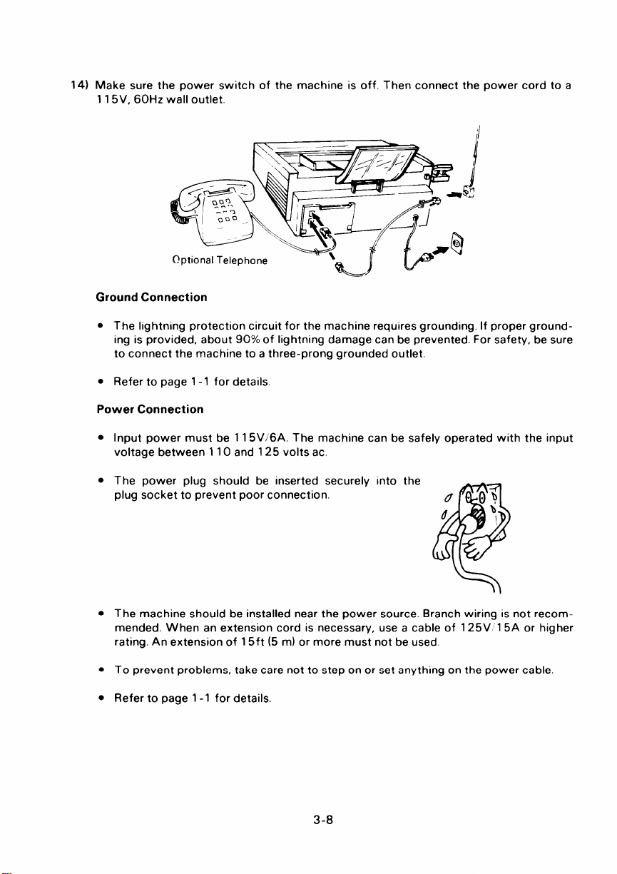
14) Make sure the power switch of the machine is off. Then connect the power cord to a
1 15V, 60Hz wall outlet.
\ .N\-
—
Optional Telephone
Ground Connection
● The lightning protection circuit for the machine requires grounding. If proper ground-
ing is provided, about 90% of lightning damage can be prevented. For safety, be sure
to connect the machine to a three-prong grounded outlet.
●
Refer to page 1-1 for details.
Power Connection
●
Input power must be 11 5V/6A. The machine can be safely operated with the input
voltage between 110 and 125 volts ac.
●
The power plug should be inserted securely into the
plug socket to prevent poor connection.
‘=,-j P“”
~ ml
d
b
1,
❑
. The machine should be installed near the power source. Branch wiring is
not recommended. When an extension cord is necessary, use a cable of 125V 15A or higher
rating. An extension of 15ft (5 m) or more must not be used.
. To prevent problems, take care not to step on or set anything on the power cable,
. Refer to page 1-1 for details.
3-8
Page 29
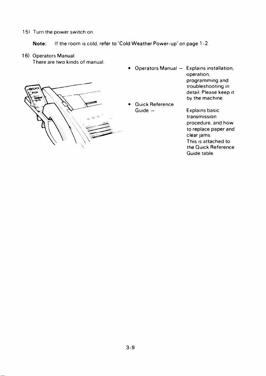
Turn the power switch on.
15)
Note:
16)
Operators Manual
If the room IScold, refer to ‘Cold Weather Power-up’ on page 1-2
There are two kinds of manual
s Operators Manual –
● Quick Reference
Guide –
Explalns Installation,
operation,
programming and
troubleshooting In
detail Please keep It
by the machine
Explalns basic
transmission
procedure, and how
to replace paper and
clear jams
This IS attached to
the Quick Reference
Guide table
3-9
Page 30

Page 31

4. OPERATION PANEL
I
---J---
No.
1
Power Indicator
2
Communicating Indicator
AVM Indicator
3
4
Confidential File
Indicator
Receive File
5
Indicator
Replace Paper Indicator
6
7
Caution Indicator
Stop Key
8
Copy Key
9
Name
I
I I
I I
2
1 I
1413{2 (1
Function
Lights when power is supplied to the machine.
Lights when the machine is transmitting or
receiving.
Lights when Auto Voice Message (AVM) is
enabled.
Lights when a confidential file is stored
in the SAF memory.
Lights when a message has been stored in
the SAF memory by substitute reception
Blinks when the paper roll is almost empty,
and lights when it is empty
Lights when a transmission failure or
a copy or document jam occurs
Press to stop communication and return the
machine to standby
Press to copy the document
10
Start Key
Press to start communication.
4-1
Page 32

.—.
No.
Ten Key Pad
11.
12.
On Hook Key
Voice Request Key
13.
Pause Redial Key
14.
15.
Quick Dial Keypad
16.
AVM Mode Key
17.
Stamp Key
18.
TEL Mode and FAX Mode
Indicators and Key
Name
Function
Use this as a telephone keypad and for
entering Speed Dial Codes.
Press this key to use the machine to make a
telephone call.
During communication, press this key If you
wish to speak to the other party.
Either:
●
Press to insert a pause when entering a
phone number.
●
Press to redial the last number dialed by the
machine.
Use a Quick Dial Key to input a preprogrammed
telephone number or sequence of features and
numbers with one touch.
Press this to use AVM programming, replaylng,
and enable disable modes
Press this to enable or disable the stamp.
Indicates the selected reception mode.
FAX Mode - automatic reception.
TEL Mode - you must activate the machine
(press Start) to receive the fax.
Press the key to change the mode
19.
GI Mode, Standard, Detail
Indicators and Key
20.
Light, Normal, Dark,
Halftone Indicators
and Key
21.
Memory Key
Indicates selected resolution. Standard - for
normal text, Detail - for drawing or small print.
G1 Mode - for transmission to a Group 1
(N. American six-minute) terminal.
These lamps indicate the selected contrast
level. Light - for light original, Normal - for
normal original, Dark - for dark original,
Halftone - for photographs.
Press this key to make a memory transmission.
4-2
Page 33

No
Name Function
22
Clear Key
23
Speed Dial Key
Function Key
24
I
25 Yes Key
26
No Key Same as above
27
Character Display
I
I
Press to clear the previously entered character,
or use as a cursor key, depending on the mode
In use
Press this key when you wish to enter a
two-digit Speed Dial Code
Press to use a numbered programming function
Use to answer questions on the Display
Displays prompts, status, warnlnngs and
selected modes
4-3
Page 34

Page 35

5. INITIAL START-UP
To enable full operation, program the followlng items Immediately after Installation
Item Mode
Date and time
Batch-number enabling
Department code enabling
Quick Dial keys and Speed Dial codes
Group dialing
Polllng ID code
RTI
TTI
Csl
Your fax terminal’s telephone number
Telephone line type
Keystroke programs
Also, contact service If you want to enable or disable the followlng features
Mondor speaker (see page 8- 18)
Protection against wrong connections (see page 8- 17)
New file report (see page 10-5)
Polhng file list output after reception (see page 1O-4)
Metmory transmission report (see page 10-5)
Error report (see page 10-2)
Use of personal password for confidential transmission (see page 8-1 )
Greater maximum document length (see page 6-1 )
Redialing – number of redials
Rediahng when using the memory
Automatic reduction override option enableidisable (see page 7-6)
Muitlcopy function (see page 8- 19)
Page retransmission (see page 7-9)
Number of page retransmission attempts (see page 7-9)
Printout of part of message contents on memory transmission reports for failed
transmissions (see page 1O-5)
Also, select the desired reception mode using the TEL Mode; FAX Mode key (see page 7- 10)
.
redialing Interval
—
number of redials
—
redial intervals
(see page 7-6)
(see page 7-9)
50
53
54
60
61
62
63
64
65
80
81
Section 9-20
5-1
Page 36

Page 37

6. RECOMMENDED TYPES OF DOCUMENT
Before transmlttlng, make sure that your document meets the followlng requirements
●
Appropriate size
Length
Width
Thickness
Weight
If the document IStoo short, enlarge It with a copier
If the document IStoo long, divide it into two or more sheets
●
Clearly written – Small, faint characters may not be transmitted clearly
●
Flat – Flatten curled or dog-eared documents before transmitting
●
Undamaged – Do not transmit torn, patched, or folded documents or documents with
bmdlng holes in the Ieadlng or trailing edges Copy such documents and send the copies
Instead.
●
Not sticking together – Sheets stuck together may double-feed
●
Not coated with carbon, wax, or vinyl – These may damage the machine
●
Without the following items – Crayon, paint, charcoal, tape, glue, cllps, staples
411nto165in
Up to 23 In can be fed manually
(This Ilmlt can be reset to 45 ft by a service technician)
581ntol181n
2 to 6 rolls
20 lb
6-1
Page 38

Page 39

7-1 Transmission
Basic Transmission
1.
—
Preparation –
7. ROUTINE OPERATION
1.
Confirm that “SET
Note:
2.
Carefully place the documents into the feeder face
down along the guide.
. Up to 30 pages (e.g. 55 kg paper) at once.
● Loosen any pages stuck together.
● Align the leading edges as shown in the dia-
● Adjust the guide to the document width.
. Transmit sheets of different width separately.
Notes:
3.
Select the required contrast. Press the contrast key repeatedly until the lamp next to the
required setting is lit.
Halftone:
Light:
Normal:
Dark:
You can
mission,
machine is in standby or receive mode.
gram.
● Refer to page 6-1 to make sure that your document is suitable for use.
. Documents may also be fed in manually, one at a time. During transmission,
DOCUMENT” is displayed on the second line of the Character Display.
prepare the machine for transdial, and press Start while the
———
READY
SET
l–— ——.
FACE
oOWN +. ..}
D=
DOCUMENT
100%
1130
SIDEVIEW
(—)
.-
the next sheet must be placed in the feeder immediately after “SET DOCUMENT” comes back on the display.
Documents containing photographs or other halftones. Transmission will be
slower.
Documents with faint characters (e.g., written with a hard pencil such as H
or 2H)
Documents with constant background color
Documents with dark patches, such as ink stains in the background.
x
0
,“.0-0.,.0.,.,
0000
EE&iEk
~ .
I
—o- . .
.
r
7-1
D
,
Page 40

4.
Select the required resolution. Press the resolution key repeatedly until the lamp next to
the required setting is lit.
Detail:
Standard:
Documents with small print or fine details
Most typewritten documents
Use the “Detail” setting with Halftone for best reproduction.
Note:
Select G1 mode if you are sending
to a Group 1 (North American sixminute) terminal. See page 8-20
for more on G1 Mode.
If you are in doubt as to the suitability of the
5.
settings:
1. Press the Copy key.
2. Check the copy quality and change the
settings if necessary.
—
Procedure –
The display should now be as shown on the right.
1.
Either:
Enable batch numbering on the printouts via the
remote terminal.
Enter the number of pages via the keypad
i)
(e.g., 12).
Press Yes (or press No to correct an error).
ii)
Or:
Press No to disable batch numbering.
Note:
Refer to page 9-3 for more information
on batch numbering.
2
Either:
i) Enter your four-digit department code via the
keypad (e.g., 1234).
Press Yes (or press No to correct an error).
ii)
Or:
Press No to by pass this step.
Note:
Refer to page 9-4 for more information
on department codes.
READY
PAGES 12 YIN
READY
~ DEPT CO DE OOOO
READY
I
DEPT CO DE 1234
100% 1130
J
100% 1130
—
100%
KPA DIN
1130
1
I
‘d
No
‘1
I
I
YIN
J
3. Enter the phone number of the other party using
either a:
. Quick Dial key (A — Z, /, &)
. Speed Dial code (from 10 to 99)
. Full telephone number (keypad)
● Full telephone number (external telephone set)
Only one destination can be entered.
7-2
I
READY
QUICK IS PEE DIK PAD
100%
1130
‘J
Page 41

Quick Dial Key:
Press the desired Quick Dial key (e.g., A) Press
1)
No to correct an error.
Press Start. The message will now be transmitted
Ii)
Speed Dial Code:
I) Press the Speed Dial Key
Ii)
Enter the required two-digit Speed Dial code (e g.,
59). Press No to correct an error.
Press Start. The message will now be transmitted.
III)
Full Telephone Number at the Keypad
i) Enter the telephone number (e.g., 5556831 ). Cor-
rect any errors with No (complete clearance) or
Clear (previous digit)
Note: For International dialing, refer to page
7-13
Press Start
Ii)
NEW YORK
OUICKNA
NEW ~O~K
DIALING t
Label or Phone No of Key A IS displayed
Phone No of Sfw(~ d 59 IS displayed
z13 5551311
sPEEDa59
OF FILE
5TAFf T
OFFICE
/
START
213 55513~1
DIALING
llEAD~
5556 t331
.00%,
KPAD
’130
START
5556831
DIALING
7-3
Page 42

Full Telephone Number at the Telephone:
i) Pick up the telephone.
ii) Dial the other party.
L—
READY
DIAL
100% 1130
HANDSET START
iii) Either:
If someone answers the line, ask that person to press the Start key after talking. Press
Start yourself when you hear a high-pitched tone.
Or:
If you hear a high-pitched tone, press Start immediately.
Note: If nobody answers the line or if there is no high-pitched tone, faxing is impossi-
ble.
—.
iv) Replace the handset when the Communicating indicator lights.
Notes: . Before pressing Start, it is possible to designate an alternative destination. If the
number of your first choice is busy, the machine will dial the alternative-number.
After entering the first telephone number, press Yes, then enter the alternative
number. This is not available with telephone dialing or when using the memory.
See page 8-15 for more details.
● [f the monitor speaker has been enabled, you will be able to hear the line condi-
tion. If the line is busy, you can press Stop and begin another operation.
7-4
Page 43

4,
The Communicating indicator will light.
The other party’s identification (RTI or CSI) will be displayed on the Character Display.
Check that you are transmitting to the intended location.
Press Stop to abort the transmission if necessary.
—
Notes: 1)
2)
3)
At this time, you can select Turnaround
Polling by pressing the Function key.
After your transmission, the remote
—
SAN JOSE
TuRNAROUND POLLING
OFFICE
—
terminal will send you any documents
that it has available in polling standby.
“TURNAROUND POLLING” is displayed If Turnaround Polling is selected. Polling ID codes must match (see
page 9-14).
Some machines may not have RT1/CSl capability or it may not be programmed into the machine. In this case the telephone number or quick-dial
label will appear on the top line of the Character Display, unless the external
telephone was used for dialing.
“A4 b A4 TRANSMIT”or “B4 - B4 ‘— – ‘—– -‘- TRANSMIT” indicates that the document is being transmitted without re- -.. .
SAN JOSE OFFICE
A4––. A4
T~ANS MIT
—
duction (see note 3 on page 7 -6).
7-5
Page 44

Notes Concerning Transmission
1.
Displays
REDIAL STANDBY
If the line is busy or contact is impossible, the
number is automatically redialed up to 2 times
READY 100%
REDIAL
STANDBY
1130
at intervals of 5 minutes. (Call for service to
change these redial parameters if necessary.)
“REDIAL STANDBY” is displayed during the intervals. To cancel redialing, remove the document from the feeder as explained in section
11-1.
If communication is still impossible after all redial attempts, the machine will ask you
for another number.
Note:
You can redial
immediately by pressing Pause/Redial if required. See page
8-17.
TRANSMISSION STANDBY
If a message is coming in at the same time as
you press Start,
“TRANSMISSION STANDBY”
is displayed below the sender’s RTI. Your docu-
SAN JOSE
TRANSMISSION
OFFICE
STANDBY
ments will be automatically transmitted immediately after the end of reception.
2.
Error Report
If transmission fails, an Error Report will be printed. Keep this; it may help the service
technician. Error codes are explained on page 11-4.
3.
Reduction
If the paper in the receiving terminal is not wide enough for the document you are sending, the machine will automatically reduce the data so that it will fit.
The machine will change the resolution from standard to detail automatically.
If you wish to have the choice of overriding automatic reduction and transmitting the data as it is,
contact your service representative,
7-6
SAN
A3––-A4
JOSE OFFICE
TRANSMIT
Page 45

2. Transmission Using the Memory
If you want to send the same document to many destinations, or If you want to program the
machine to send a document at a later time, you will need to use the memory
Before you decide to use the memory, check the Memory Space Display In the top right of
the character display If this reads OYO,there IS no room To detemine whether there IS room
for your document, bear In mind that an average page of a business letter takes up about 2~L
of the memory space
If you need to make some room for a high-pnority document, refer to page 9-18 Also note
that function 2 can be used If You wish to send later to one destination only and you do not
wish to erase a memory file (see page 8-3)
Note: In memory mode, pages are automatically batch-numbered at the recewer’s termi-
nal If batch-numbering has been enabled (function 53)
The procedure for
transmission ISas follows
– Preparation –
This IS the same
as for basic transmission Refer to
page 6-1
– Procedure –
1) Press the Memory key
If department code IS not enabled (function 54 is
off) go to step 3
2) Either:
Enter your four-digit department code at the
1)
keypad (e.g , 1234)
Press Yes (or press No to correct an error)
11)
Or:
Press No to by pass this step
Note:
Refer to page 9-4 for more Information
on department codes
3) Either:
If you do not want to send later, press No and go to
step 6
ME M3RY
SEND LATER
MEMORY
*
CIUICK SPFF[
TRAN5
TRANS
!A(I:JE
Y P/
MCJLE
KPAG
Or:
Press Yes
7-7
ME MOP? TRANS
TIME ,. 30
MOLE
KEYPAD{
Page 46

Enter the required transmission time (24-hour
4)
clock) at the keypad. To correct an error, press No.
Example: 2:30 a.m.
Caution:
If you take more than 40 seconds to
enter the time, the display will reset to
the present time.
Press Yes.
5)
6)
Enter the destination telephone number(s) as:
. Quick Dial Key(s)
. Speed Dial Code(s)
. Full telephone number(s) at the keypad
● Group(s)
. Any combination of the above.
Press Yes after each entry.
Quick Dial Key:
Press the desired Quick Dial key (e.g., A). Press No
to correct an error.
Speed Dial Code:
Press the Speed
i)
Dial Key.
ii) Enter the required two-digit Speed Dial code
(e.g., 59). Press No to correct an error.
Full Telephone Number at the Keypad:
MEMORY TRANS
TIME 02 30 KEYPAD/Y
MEMORY
* QUICK SPEED KPAD
NEW YORK
OUICK~A
Phone No of Speed#59 IS d!splayed
213-5551311
sPEED #59
TRANS
/
MODE
—
MODE
OFFICE
Y(N
YIN
Enter the telephone number (e.g., 5556831 ). Correct any errors with No (complete clearance) or
Clear (previous digit).
MEMORY TRANS MODE
5556831
KPAD Y
A group is a preprogrammed set of addresses. For more information on these, refer to
page 9-12.
To enter a group, first press,, then the number of the desired group.
Caution:
If you enter
● then O (zero), the document will be sent to all the numbers
stored in groups 1 thru 7.
7-8
Page 47

7) After entering all destinations, press Start.
The document WIII be scanned and stored in the memory. The Remaining Memory indicator will count down as the message is stored. A New File Report will be printed after the
message is stored The machine then returns to standby (unless you selected Immediate
transmission, in which case the message will be sent now) Do not switch the power off,
or the memory WIII be erased. After transmission, a Memory Transmission Report IS printed
Caution:
Notes:
While the terminal IS scanning the document, do not leave the machine
If one of the following symptoms occurs,
completely:
● MEMORY OVERFLOW appears on the display until the machine returns
your document was not stored
to standby.
c No new file report is printed.
There are no other indications of memory overflow, so you should keep a
close watch on the machine during storing,
1 Redlaling
In memory mode, a terminal can be redialed up to 4 times (at Intervals of 5,
5, 10, and 5 minutes). After each failed redial attempt, the Caution Indicator
flashes and the machine asks you to press Stop
After all redialing attempts fail, a Memory Transmission Report and an Error
Report are printed and the message is erased from memory
To cancel redialing, erase the document from memory with function 67
2 Page Retransmission
If ECM is enabled (function 83), any parts of a page that were not sent correctly will be resent automatically If ECM is not enabled, the complete page
will be resent; the maximum number of retransmission attempts w 2 but this
can be increased to 3 by service.
3. Restrictions
Maximum number of addresses per file: 100
Maximum number of files: 99
Maximum total addresses in all files: 300
Note that the total number of addresses stored in the machine for polling reception and memory transmission, when added together, can not exceed
300,
4. Memory Standby
This is displayed if a message is coming in at the same time that you
pressed Start. Your message will be stored after the end of reception
7-9
Page 48

7-2 Reception
During reception, the Communicating indicator will light.
– Automatic Reception –
The machine will receive documents unattended if:
a) The power switch is on.
b) The machine is set for automatic reception (the FAX Mode indicator should be lit).
– Manual Reception –
When the machine is in the “TEL” (manual) mode, reception can be accomplished by one of
the following procedures:
●
1.
Phone rings
●
Pick up the handset.
●
Establish voice contact with the calling side.
●
When the calling side is ready to transmit to you, remove any documents from the
document feeder and press Start. (The calling party should press Start after hearing
the high pitched tones from your machine.)
●
Reception will begin.
●
Hang up the handset.
2. ●
Phone rings
●
Pick up the handset
●
A one-second tone can be heard every 3-5 seconds.
(This indicates that an automatic dialing facsimile terminal is calling.)
●
Remove any documents from the document feeder and press Start.
●
Reception will begin.
●
Hang up the handset.
If you share the fax line with a telephone and ?f you receive a lot of telephone calls on that
line, you should keep the terminal in TEL mode. You will not be able to receive telephone
calls if you change to automatic mode.
To change the reception mode, press the key below the TEL Mode and FAX Mode indicators
until the required indicator is lit.
Normal transmission is still possible if you are in TEL Mode.
Note: If a message comes in while you are making a copy, remove the documents from
the feeder and press Stop.
If reception fails, an Error Report will be printed. Keep this; it may help the service
technician. Error codes are explained on page 11-4.
7-1o
Page 49

– Confidential File –
When the Confidential File Indicator is lit, a confidential message has been recewed and
stored in the memory To print this message, you must enter the correct password
1 Press the Function key, then enter 76
2 Press Yes
3 Enter your password
Example. 0123
MODF NO “b
PRINT
CO NFIENT IAL
PASSWORD
■ ■ ■ ■
CONFIDENT (AL
0 “23
KEf PAD
GOPY N
4 Press Copy
If you enter the wrong password, “INVALID PASS-
WORD”
IS displayed and the machine will return to
standby
Note:
The sender may have over-ridden your
password (refer to section 8-1)
Check with the sender. (Print the TCR, if
necessary, to find out who the sender is.)
5 The message is printed, then the machine returns to standby
If you have forgotten the password, either:
● Call service
● Contact the senders and ask them to over-ride your password (refer to section 8-1)
This IS only possible if they are using a FAX07, FAX1 O, FAX15, FAX20, FAX25,
FAX35, FAX60, FAX65, FAX1 OE, FAX20E, FAX60E, FAX70E, FAX1000L, R1
R61O, R830, or another FAX75.
Don’t forget to find
out what password they will use for the transmission
– Receive File –
YN
00,
When the Receive File indicator is lit, a message was received but stored in the memory because the printer was not working (because of a jam, or because the copy paper ran out)
Check the indicators to find out where the fault is, Then clear the fault
DO NOT switch the power off, as this will erase the memory The message will be printed
automatically after the fault IS cleared.
Refer to pages 7-14 and 11-2 for Information on clearing faults.
This feature, known as “Substitute Reception”, only works if there IS room In the memory.
7-11
Page 50

7-3 Ringing Telephones and Buzzers
Single Ring –
–
A message is coming in. It will be received automatically. Do not pick up the handset or the
telephone.
– Continuous Ringing –
If the FAX Mode lamp is lit, either:
a) Power is switched off (the external telephone will ring).
b) The other party requires voice contact (the internal buzzer will ring). Pick up the handset,
press the Stop key and speak.
Refer to “Voice Request” on page 8-14.
If the TEL Mode lamp is lit:
A message is coming in and you are in manual reception (TEL) mode.
1) Pick up the handset and speak to the caller.
Note:
If the calling terminal is in auto-dial mode, you will not be able to speak to the
caller. You will hear modem-generated tones. Press Start during the initial highpitched tone.
2) Press Start after speaking.
3) When the Communicating lamp lights, hang up.
7-4 Making Telephone Calls (On-hook Dialing)
The machine can be used for making regular telephone calls.
1) Make sure that the machine is in standby mode.
2) Press the On Hook key.
3) Enter the telephone number at the keypad as a
Quick Dial key, Speed Dial code, or full telephone
number.
Caution: If you are making a telephone call, do
not press Start.
4) Listen to the monitor speaker.
When the other party answers, pick up the handset,
and speak.
7-12
[READY
SET DOCUMENT
ON HOOK DIAL MODE
100%
OUICK/SPEED/K PAD
1130
Page 51

7-5 International Dialing
There are two ways
1 Direct diallng using the International Access Code “01 1 “ If this service IS provided in
your area
2. Dlaiing ‘“O” (zero) and using operator assistance
– Direct Dialing –
Dial as follows:
1) Dial 011 + Country Code.
2) Press the Pause key if using the fax terminal’s built-in keypad
3) Dial the City Code and Local Number
– Operator-assisted Dialing –
1) Dial “O” (zero)
2) Tell the operator you wish to place an overseas call.
3) Tell the operator
. The country, city, and phone number of the called party.
. You are making a data call (to avoid communication errors, the operator WIII not stay
on the Ilne during dialing)
Note: This Information is based on using ATT as the long distance carrier
Call your long distance carrier for the dialing codes that they use.
7-13
Page 52

7-6 Replacing Paper
When the Replace Paper indicator blinks, the roll has about 33’ left.
When the Replace Paper indicator remains lit, the roll is empty. Install a new roll as follows.
A
328 ft. roll must be installed for the near-end indication to work correctly.
1.
Press the top cover release button and open the
top cover until it locks.
2.
Take out the empty roll and pull out both spools.
Insert the spools in a new paper roll and install it
with the leading edge at the top of the roll and
facing the front of the machine,
------
Q -~k:~?gy: - ~
b ‘~;
~
:’-
‘ ;\Q ~
;>” /’
.,
“~$~ \ ‘ f
\<: “$’”
J ,,P“
6
d
3.
Pull out the leading edge about 8 ins and insert
under the green line in front of the platen roller,
4.
Close the top cover.
A paper cycle is made automatically.
Note: If there is no paper cycle, check that the
If you want to change the paper roll size, refer to
the top of page 3-5.
roll is installed correctly.
7-14
w
Page 53

7-7 Daily Care
If the room is cold, refer to ‘Cold weather power-up’ on page 1-2 before swltchlng on
1
Check the Caution Indicator If It IS lit, see the Character Display and correct the fault
2
Place a document In the feeder and press Copy
Check that the copy quallty IS satisfactory
3
Open the scanner
Gently wipe the exposure glass, whale plate and the rollers with a clean soft damp cloth
-r -
4
Open the printer and remove the roll
Gently wipe the thermal head and the platen roller with a clean soft cloth moistened with
alcohol
Caution: Do not use water
5
Clean the machine’s exterior with a clean soft dry cloth Do not use a cleanlng agent
7-15
Page 54

7-8 Refilling the Stamp
When the red mark made by the document stamp is getting faint, add a drop of ink to the
stamp as explained below.
1. Press the ADF release button and open the ADF.
2. Cut the tip off the ink bottle, if the bottle is unopened.
3. Place only one drop of Ink on the stamping surface.
4. Close the ADF.
I
7-16
Page 55

8. SPECIAL FEATURES
8-1 Confidential Transmission
A confidentially transmitted message IS stored in the
memory of the receiving terminal. ‘The message can
only be printed out after authorized personnel at the
remote terminal enter the correct password.
For extra security, you can specify the password for
the message if the receiver is an R61 O, FAX70E,
FAX1OOOL, R830, FAX35 or another FAX75. This
personal password WIII override the password that the
remote terminal user has previously stored in his machine, which would normally be used for printing confidential messages
operator before using this feature
Co-ordinate with the receiver
>
Notes: .
Confidential transmission can not take
place If the receiving terminal has no
memory, or if the receiver’s memory IS
full,
. Only one address can be designated.
● Confidential transmission cannot be
made from memory.
8-1
Page 56

– Procedure –
1)Press the Function key.
“ IEnter’1’ at the keypad.
L!
Place the document into the feeder.
3)
Select the contrast and resolution.
READY 100%
1130
I .SE1-E12~ MOL)E .. K,.13
CO NFID’L TFIANS MODE
SET DOCUMENT
CO NFID L TRANS
PAGES 00
—
—
MODE
KEYPAD/N
I
.
I
4)
Enter
the number of pages,
if required, and press
Yes.
Enter
5)
your department code,
if required, and press
Yes.
6)
Either:
Enter a personal password.
i) Press Yes.
ii) Enter the four-digit password at the keypad
(e.g., 1234). Press No to correct any errors.
iii) Press Yes to confirm this password.
The receiving operator must enter this password to
print the message.
Or:
Press No if a personal password is not required.
The receiver operator will use the password that
was stored in their machine.
7)
Dial the other party using a Quick Dial key, Speed
Dial code, or full telephone number (keypad or telephone set).
(e.g., Quick Dial key A)
CO NFID L TRANS
DEPT CO DE QOO@ KP AD/N
I
CO NFID L TRANS MODE
uulwrluc
———
CO NFID L TRANS MODE
Nlla L
MODE
—
Y/N,
Iu,
LLu?fE :EYPADI
CO NFID L TRANS MODE
1234
ID
I
~__ —-
CO NFID L TRANS
OUICK/SPEED/K PAD
‘a~z~--– ‘-
NEW YORK
OUICK#A
L.
OFFICE
MODE
START
YIN
—J
—J
~
I
!
I NO
*
I
8-2
Page 57

8) Press Start
NEw YORK
DIALING
OFF CE
Notes: CONFIDENTIAL STANDBY
This message on the LCD panel indicates
that a message IS now being recewed.
The confidential transmission will be auto-
READY
CONFIDENTIAL
’69+
“130
S- AND8Y
matically made immediately after reception
CONFIDENTIAL N A
This Indicates that the remote terminal
cannot receive confidential messages
CONFIDENTIAL N A
(e g., full memory, no memory, incompatible). The number will be redialed after five
minutes.
READY 10CI*
RE DIAL
STANDBY
1130
8-2 Send Later Transmission
If the memory IS full and you want to send a message later, you can use this function If you
do not wish to erase any memory files.
This feature delays transmission until a time selected by the operator This feature can be
used to take advantage of off-peak line charges The designated time must be within 24
hours of entry
Note: Transmission can only be made to one location However, alternate number dial-
ing may be used
8-3
Page 58

—
– Procedure –
Press the Function key.
1)
2)
Enter 2 at the keypad.
3)
Place the document into the feeder, Select the contrast and resolution.
4)
Enter the number of
quired, and press Yes.
Enter your department code at the keypad, if re-
5)
quired, and press Yes.
Enter the required transmission time (24-hour
6)
clock). To correct an error, press No.
pages at the keypad, if re-
,
READY
SELECT MODE
SEND
LATER
SET DOCUMENT
SEND
LATER MODE
PAGES 00
SENO LATER
DEPT
CO DE OOOO KPAD N
SEND LATER
TIME 1130
100%
■ -
MODE
KEYPAD N
MODE
—
MODE
KEYPAD Y
1130
KPAD
Example: 2:30 a.m.
Caution:
If you take more than 40 seconds to
enter the time, the display will reset to
the present time.
Press Yes.
7)
8) Dial the other party using a Quick Dial key, Speed
Dial code, or full telephone number at the keypad
(e.g., Speed Dial 31.)
9) Press Start.
To cancel the operation, remove the document from
the feeder.
SEND LATER MODE
TIME
02 30 KEYPAD Y
SEND LATER
OUICK SPEED KPAD
Tel No In
\
213 5553111
sPEED #31
READY
(02 301
MODE
Speed# St
100%
TRANS
START
1130
STANDBY
8-4
Page 59

8-3 Transfer Request
This feature WIII cause a document to be transmitted to up to 30 destinations vla a broadcasting station
r 1
The message IS stored In the memory of the broadcasting transmitter and transmitted to
each designated recewer In turn
After the end of broadcasting, a Transfer Result Report IS sent from the broadcasting station
to the requesting station
Notes: .
Caution:
The ID codes of the requesting and the broadcasting stations must be Identical
This code must be agreed upon and stored using function 62 before using this
feature
●
Your fax telephone number must also have been programmed, using function
80, before using this feature.
●
Only a machine with the transfer broadcasting function can be used as a broadcasting station
Raplcom 5000 with SAF, 610, 830
eg
Rlcoh FX5000 with SAF, FX830
Rlfax 2313HS, 231 7HS, 1300HS, 5100S, 610S
The Raplcom 5000 with SAF, Ricoh FX5000, and Rlfax 231 3HS WIII not
send back the transfer result report after broadcasting If there IS one of
these In your facsimile network, contact Rlcoh Service
●
Your machine can only make a transfer request
●
Transfer request cannot be made with transmission from memory
The broadcaster and receiver numbers must all contain the International dialing
code and the country code, even If they are all In the same country, and even If
they are all In your own country
8-5
Page 60

—
rroceaure —
.
Press the Function key.
1)
2)
Enter 3 at the keypad.
Note:
If ‘TRANSFER TRANS MODE’ does not
appear, your fax telephone number is not
programmed. You should program it now.
See page 9-19.
Place the document into the feeder. Select the con-
3)
trast and resolution.
4)
Enter the number of
pages at the keypad, if re-
quired, and press Yes.
5)
Enter your department code at the keypad, if re-
quired, and press Yes.
6)
Enter the broadcaster’s number, either as a Quick
Dial key, Speed Dial code, or full telephone number
(not using the telephone).
Example: Quick Dial key A
—
100’%
TRANS
TRANS
—
1!30
MODE
MODE
KEYPAD N
MOOE
MODE
KEYPAD
YN
READY
SELECT MODE ¤~ KPAD
TRANSFER TRANS
SET DOCUMENT
TRANSFER TRANS
PAGES 00
TRANSFER
OEPT CO DE 000 OK PAD N
TRANSFER
0b113K#s AFm
NEW
YORK OFFICE
Qbl CK#SAFA
7) Press Yes (or, press No to correct).
8) Either:
Enter a receiver number, either as a Quick Dial key,
Speed Dial code, or full telephone number (not
using the telephone).
Example: Quick Dial key B
8-6
TRANSFER TRANS MODE
*
QUICK SPEED KPAO
TRANSFER TRANS MODE
OUICK#B
KEYPAD Y
Page 61

Or:
Enter a preprogrammed group of receiver numbers
(e.g., Group No. 1).
i) Press
●.
ii) Enter 1 at the keypad.
Note: Entering O (zero) will cause you to transfer
to all terminals In all the groups (1 – 7).
Take care not to enter O unless so desired.
TRANSFER TRANS
**
Groups Label
DISTRIBUTORS
{
**.
MODE
KEYPAD
YN
iii) Press Yes (or press No to correct),
)) Either:
Enter another receiver number or group of numbers; go back to step 8
Note
Do not enter more than 30 receivers for
one transfer operation
Or:
If all required receivers have been designated,
press Start
Jotes: TRANSFER TRANS NIA
If this is displayed, the designated broadcaster cannot transfer your message (its
memory may be full, or it may not have
the transfer function)
The broadcaster will be redialed after 5
minutes.
TRANSFER STANDBY
This means that a message was being received when you pressed Start. Then
“TRANSFER STANDBY” is displayed. Transfer will start after the end of reception.
TRANSFER TRANS
OUICK#D * KPAD START
MODE
NEW YORK OFF{LE
DIALING
8-7
Page 62

8-4 Polling
1. Polling Reception
This feature allows you to call a remote terminal and instruct it to send you whatever
documents it has stored in polling standby for you to pick up.
Polling reception can be immediate or time-designated (Poll Later).
Notes: For polling reception to be successful:
1) The remote terminal(s) must have the polling feature.
2) The remote terminal(s) must have documents in polling standby; check with
the remote terminal users.
3) The remote terminal(s) must have the same polling ID code as yours, unless:
. The remote terminal specifies free polling — ID codes will not be checked.
● You enter a personal ID in step 6 —
code for this transmission only; you should enter the ID code of the remote
terminal that you want to poll.
Co-ordinate the ID codes used by the terminals in your polling network.
Normal reception can still take place if you are in Poll Later mode.
this will override your stored polling ID
8-8
Page 63

—
Procedure –
Press the Function key.
1)
2)
Enter 4 at the keypad,
Press Yes
3)
4)
Enter your department code at the keypad, if required, and press Yes.
5)
Either:
Poll at a later time
I) Press Yes
ii) Enter the required time (24-hour clock) at the
keypad. To correct an error, press No.
Note: The time must be within 24 hours of
the present
Example: 2.30 am
READY
SELECT MODE
READY ,00%,
PROGRAM
POLLING
DEPT CO DE 000 OK PAD N
POLLING RECEIVE MODE
POLL LATER’ YN
POLLING
TIME 1130
POLLING RECEIVE MODE
TIME
“00%
PO LLING7 Y N
RECEIVE MODE
RECEIVE
—
02 30 KEYPAD Y
—
’130
● m KPAD
“30
MODE
KEYPAD Y
?
iii) Press Yes to confirm this time.
Or:
Select immediate polling.
Press No
8-9
POLLING RECEIVE
PERSONAL ID” YN
MODE
-
Page 64

Either:
6)
Enter a personal ID (see note 3 at the beginning
this procedure for details about the personal ID).
of
i) Press Yes.
ii) Enter the required
keypad (e.g., 1234).
four-digit code at the
Correct any errors with
No.
iii) Press Yes.
Or:
Press No if a personal ID is not required
7) Either:
Enter a fax number either as a Quick Dial key,
Speed Dial code, or full telephone number (not
using the telephone).
Example: Quick Dial key B
Or:
Enter a preprogrammed group of receiver numbers
(e.g., Group No. 1)
i) Press
● .
ii) Enter 1 at the keypad.
Note:
Entering O (zero) will cause the machine
to poll all destinations registered in
groups 1 thru 7.
ID 0000
r
I
POLLING
ID 1234
L—
RECEIVE
—
RECEIVE MODE
MODE
KEYPAD
~ .—_.
POLLING RECEIVE MODE
I
*/ OUICK/SPEED/KP AD
—
POLLING RECEIVE
OUICK#B
L
—
.4
MODE
KEYPAD/Y
—
POLLING RECEIVE
**m
L
—=’s’”’”
DISTRIBUTORS
**1
—
KEYPAD
.—1
MODE
—.
YIN
J
—1
I
I
-]
YIN
8) Press Yes to confirm or press No to correct the
entry.
9) Either:
Enter another remote terminal number or group of numbers; go back to step 7.
Note: Do not enter more than 100 addresses for each polling operation.
Or:
If all required terminals have been designated, press Start.
8-10
Page 65

If polling is time designated, a polling file list WIII be
printed and the unit WIII return to standby.
PRINT
SET
POLL
DOCUMENT
FILE LIST
If polling IS immediate, the terminal will begin to
dial
If the polled location is busy, your terminal will
redlal up to twice at intervals of five minutes
Notes:
To cancel a preprogrammed time-designated polling reception operation, use
mode 66 (see page 9-1 7)
POLLING RECV STANDBY
If this is displayed, a message was coming in at the designated polling time or
when you pressed Start Polling will begin Immediately after the end of reception
RestrictIons
Maximum number of destinations per polling file 100
Maximum number of polling files: 8
Maximum number of destinations over all polling files. 300
Note that the total number of addresses stored in the machine for polling reception and memory transmission, when added together, can not exceed 300
CAUTION:
Delayed programmed polling files are erased automatically after polling
unless there is a line problem
2.
Polling Transmission
This feature allows you to leave a document in the feeder
up This will place your terminal in polling standby mode
Reception can take place as normal in polling standby mode
213
5557324
DIALING
for a remote terminal to pick
Note:
Polling transmission can be either free or secured,
Free polling –
Polling ID codes will not be checked. Any compatible terminal can poll yours.
Secured polling – Polling ID codes will be checked If a machine with a different
ID code tries to poll your terminal, it will not succeed
8-11
Page 66

– Procedure –
IPress the Function key.
1)
2)
Enter 4 at the keypad.
Press No.
3)
4)
Place the document in the ADF.
Select the contrast and resolution.
Enter the number of pages, if required, and press
5)
Yes.
Enter your department code, if required, and press
6)
Yes.
7)
Either:
Enter a personal ID (see note 3 on page 8-8 for
details on this ID).
I) Press Yes.
ii) Enter the required code at the keypad (e.g.,
1234). Correct any errors with No.
READY
SELECT
READY 100% 1130
PROGRAM
POLLING TRANS MODE
SET DOCUMENT
POLLING
PAGES 00
POLLING TRANS
DEPT CO DE 000 OK PAD N
POLLING TRANS
PERSONAL ID?
POLLING
ID 0000
POLLING
ID
1234
100’% 1130
■ = KPAO
MODE
POLLING? Y N
TRANS
TRANS
TRANS MODE
MODE
KEYPAD N
MODE
—
MODE
MODE
KEYPAD ~
YN
No
1
I
1
‘i
Ye
YN
-i-l
iii) Press Yes. Your machine will go into polling
standby (secure mode). Go to step 9.
POLLING
CHECK ID
TRANS
CODE7
MODE
YN
Or:
Press No if a personal ID is not required.
Then, either:
8)
Press No to select free polling.
Or:
Press Yes to select secured polling.
Your terminal is now in polling standby. When your terminal is polled, it will scan and
9)
—
READY
POLL STANDBY FREE
—
READY
POLL STANDBY SECURE
100% 1130
100%
1130
transmit the document.
To cancel poll standby, open the scanner and remove the document.
8-12
It
4
Yes
1
II
J
Page 67

3, Turnaround Polling
During routine transmission, If you select this feature, your terminal WIII automatically poll
the terminal that you are sending to and ask d to send you any documents that It has on
polling standby (see page 8-11 )
You will have to pay line charges for both the transmission and reception of the polled
document However, the overran line charges are less than for the two calls that would
otherwise be needed for this operation
1 Perform the normal transmission operation.
a) Insert the document
b) Select the appropriate resolution and contrast
c) Dial the remote terminal
d) Press the Start key
2 When the Communlcatlng lamp Ilghts on the operation panel, press the Function key
3 As transmission takes place, the RTI or CSI of the remote machine appears In the dis-
play.
4 After transmission IS complete, the display goes blank The machine goes Into the
polling reception mode
5 The machine emits a tone when reception of the document IScomplete
8-13
Page 68

8-5 Voice Request
With this feature, you can speak with the remote terminal operator before or after transmis-
sion or reception. You can also interrupt communication to speak to the other party.
For Voice Request to be effective, both terminals must:
● Have a telephone or handset connected.
. Have the voice request function.
w
Note:
To speak with the remote terminal operator before sending a message, dial the
remote terminal on the telephone connected to your terminal and proceed as described on page 7-4 (Full Telephone Number at the Telephone).
Un
o
0“0
0 “00
0.,., “o
..”
0000 °0’0
~ :+ ~
000.
.-.
“-
—Stop key
- VoiceRequestKev
1 To talk with the remote terminal operator at the end of communication.
If you are transmitting:
1) Start the transmission. Wait for the Communicating indicator to light.
2) Press Voice Request.
3) When your machine sounds a tone, pick up the handset, press the Stop key, and
speak.
Note:
If your machine does not sound a tone, the remote terminal operator did not
come to the phone. The line will be disconnected automatically.
4) Replace the handset after speaking.
If you are receiving:
1) Press Voice Request while the Communicating indicator is lit.
2) When the machine sounds a tone, pickup the handset, press Stop, and speak.
Note:
If your machine does not sound a tone, the remote terminal operator did not
come to the phone. The line will disconnect automatically.
3) Replace the handset after speaking.
8-14
Page 69

2 To talk with the remote terminal operator during a multi-page communication
If you are transmitting a fax:
1) Start the transmission. Wait for the Communicating indicator to light
2) Press Voice Request, then press Stop, Transmission will be Interrupted at the end of
the current page.
3) When your machine sounds a tone, pick up the handset, press Stop, and speak.
Note:
4) To resume communication, ask the remote terminal operator to press Start
5) Press your Start key when you hear a high-pitched tone
6) Replace the handset when the Communicating indicator lights
If you are receiving a fax:
1) While the Communicating indicator is lit, press Voice Request, then press Stop. Transmission will be interrupted at the end of the current page
2) When your machine sounds a tone, pick up the handset, press Stop, and speak
Note:
3) After speaking, press Start.
4) Replace the handset when the Communicating indicator lights
If your machine does not sound a tone, the remote operator did not come to
the phone Communication resumes and the voice request is automatically
repeated at the end of transmission
If your machine does not sound a tone, the remote terminal operator dld not
come to the phone. Reception will resume The voice request will be auto-
matically repeated at the end of reception.
8-6 Alternative Destination
During the keypad entry procedure for basic transmission, you can designate two destina-
tions. If the first choice of destination cannot be reached, the machine will send the
message to the alternate location. If the first destination is reached, the alternative will be
disregarded
a
\
8-1 5
Page 70

Proceed as for basic transmission:
1)
i) Place the documents in the ADF.
ii) Enter the page count and department code if re-
quired.
r—
. —
—. —
‘—
READY
100%
OUICKISPEEDIK PAD
1130
——
2)
Enter the first choice of destination.
Example: Key A.
Press Yes.
3)
4)
Enter the alternative destination.
Example: Key C.
5)
Press Start.
Note: If the first destination is busy, your unit will
-–-–--’=— ‘NEW YORK
I
Oul CK+A
I__
l-”-uc K ‘ g ___ ‘_E:’: ‘___
CHIC AGOX OFFICE
r
OUICK+C
.——
NEW YOFtK
OFFICE
Labelof keyC
OFFICE
START
—
START
LD’A:’N–G
wait for ten seconds before dialing the alternative location. If the alternative is also busy,
your unit will redial the first location about four
minutes later.
Both numbers will be redialed until one of them answers, or until the limit expires
redials per destination).
This feature is not available for polling or transfer request, or transmission from memory.
(2
8-16
Page 71

8-7 immediate Redial
When the other party is busy, the machine will automatically redial after 5 minutes. However, you can redial sooner by pressing the Pause/Redial key. This function is available when
your machine is standing by. Even if Immediate Redial is used, the maximum number of redials will still be two.
Note: Immediate Redial cannot be used in the CONFIDENTIAL, TRANSFER REQUEST,
POLLING or MEMORY modes when in Redial Standbv
1) Either:
Keep the handset on-hook.
Press the Pause/Redial key
then the Start key.
Redialing starts immediately.
Or:
Pick up the machine handset.
Press the Pause/Redial key.
Redialing starts immediately.
I
If the number is busy, it will be automatically redialed five minutes after the original dialing
attempt.
8-8 Protection Against Wrong Connections
I
For this function to
1) The CSI of the remote terminal called must be the same as its telephone number.
2) The function must have been enabled in advance by a service technician.
Your machine compares the last eight digits of the dialed number with the last eight digits
of the received CSI. If they do not match, the message will not be sent. Spaces and pauses
are disregarded.
Notes:
. This function removes the possibility of the telephone network connecting you
to the wrong location. However, if you dial the wrong number, the message will
not be stopped. So you should still check the RTI or CSI that is displayed on the
Character Display and press Stop if the wrong one is displayed.
● This function does not work if you dialed the other party with the external tele-
phone.
8-17
Page 72

8-9 Using a Keystroke Program
A keystroke program is a preprogrammed set of features and addresses that have been
stored into a Quick Dial key. See page 9-26 for details on storing a keystroke program.
To use a stored keystroke program, follow one of the
following procedures.
—
Transmission –
Place the documents into the feeder.
1)
2)
Select the required contrast and resolution.
Enter the page count and your department code, if
3)
required.
Press the key into which the desired program has
4)
been stored.
—
Polling Reception –
Press the key into which the desired program has
1)
been stored.
8-10 Monitor Speaker
This function can be used to listen to the telephone line during transmission, reception or
dialing.
Each function can be enabled or disabled by a service technician. If enabled, the monitor
speaker will always be working during the operations indicated below.
Transmission Mode
1)
In automatic dialing mode (not using the handset or
telephone), the ringback tone, busy tone, operator’s
voice, or the answer back tone from a facsimile machine can be heard through the monitor speaker.
After the answer back tone the machine goes into
transmission mode, then the monitor is cut off.
2)
Receiving Mode
When the machine goes into receiving mode, the
operator’s voice or the signal from the remote
terminal can be heard. After receiving the signal
from the remote terminal, the monitor is cut off.
Note:
The speaker volume can be controlled
with function 55. See page 9-5.
8-18
Page 73

8-11 Using the Machine as a Copier
You can make up to 99 copies of a document using
the following procedure:
1 Press the Function key then enter 77.
2 Press Yes
3 Place the document in the ADF
4 Enter the required number of copies.
Example: 10
Press No to correct an error
5 Press Copy.
The document is scanned and stored into the
memory Then the copies are made. After this, the
document is erased from memory and the machine
returns to standby.
MODE NO 77
MULTI
COPY”
DOCUMENT
SET
KEYPAD COPY
01 SETS
COPY N
10
SETS
YN
8-19
Page 74

8-12 G1 Mode
This unit is compatible with Group 1 terminals (i.e.,
North American six-minute terminals).
To make a G1 transmission:
1. Press the resolution key until the G1 Mode indicator lights.
2. Place the document in the ADF.
3. Select the contrast, then dial.
4. Either:
If someone answers the line, ask that person to press the Start key after talking. Press
Start yourself when you hear a high-pitched tone (the answer-back tone).
Or:
If you hear a high-pitched tone (the answer-back tone), press Start immediately.
Note:
If nobody answers the line or if there is no high-pitched tone, faxing is impossi-
ble.
5. Replace the handset when the Communicating indicator lights.
Note that the following features cannot be used with G1 Mode.
● Confidential Transmission
● Transfer Request
● Polling
. Voice Request
● Protection against wrong connections
. Detail resolution
● ECM
. RTI, TTI, and CSI
8-13 Document Stamping
If the stamp is enabled, it will make a pink circle at the bottom of the page if it was received
correctly at the other end. This will help you to check whether all pages of your document
were received. The stamp is enabled when the Stamp indicator is lit. Press the key below
8-20
Page 75

9. FUNCTIONS AND PROGRAMMING
This machine has a wide range of programmable functions. Study these functions to get the
most out of the machine. Program these functions while the machine is in standby mode.
If you want to return the machine to standby mode at any time while programming, press
the Function key.
Note: .
If you entered the wrong function number, press the Function key again The
machine will return to standby.
●
When waiting for your response to a prompt, the system will time out and
return to standby if a response is not input within 40 seconds
If this occurs, you must repeat the entire procedure until you return to the point
you were at before the system timed out.
●
All programmed items remain in the memory even if you switch the power off.
9-1 Clock Adjustment
Press the Function key, then enter 50 at the keypad.
1)
Press Yes.
2)
Either:
3)
Change the item at the cursor (blinking item).
● Increment with #.
Functlon key
MODE NO 50 YN
ADJuST CLOCK?
DATE & TIME Y*bc
APR 14 87
DATE &
MAY 14 87
TIME
1130
Y*#c
1130
● Decrement with ,
Or:
Move the cursor with Clear.
Or:
Press Yes to store the displayed data into the clock
and go on to function 51.
Or:
Press Function to store the displayed data into the
clock and go back to standby.
9-1
DATE & TIME Y* ’#c
MAY 14 87 1130
—
L—
MODE NO 51
TO TAL# Tx’Rx
YN
Page 76

9-2 Communicated Page Counter Display
These counters display the number of pages your
terminal has transmitted (TX) and received (RX).
1) Press the Function key and enter51 at the keypad
MODE
NO 51
TO TAL# TX RX
—
YN
2) Press Yes
3) After checking the counters:
Either:
Press Yes to check the sheet feed counters.
Or:
Press Function to return to standby.
9-3 Total Scan and Print Counter Display
These counters display the total numbers of sheets
that your terminal has scanned and printed out. This
also includes sheets scanned and printed in copy
mode.
1) Press the Function key and enter 52 at the keypad.
2) Press Yes.
3) After viewing the counters:
Either:
Press Yes to go on to function 53.
Or:
Press Function to return to standby
RX 000280
— —
MODE NO 52
TO TAL #SCAN PRINT
PAGE
—
COUNT?
.-
READY 100’%
SET DOCUMENT
MODE NO 52
TO TAL #SCAN/PRINT
SCAN 054330
PRINT 045300
MODE NO 53
SELECT
READY 100’%
SET DOCUMENT
.—
~130
1130
y(N
J
—
YN
—
-—
ytN
9-2
Page 77

9-4 Batch-number Enabling
This function allows you to instruct your terminal to batch-number multl-page documents
as they are printed out at the other end.
If you disable this function, the “PAGES:OO KPAD N“ prompt wtll not appear during routine
use
1) Press the Function key and enter 53.
2) Press Yes.
3) Either:
● to enable batch numbering.
Press
Or:
Press # to disable batch numbering
4) Either:
Press Yes to go to function 54
Or:
Press Function to return to standby.
MOC)E NO 53
SELECT
PAGE
ON *
PAGE
ON *
PAGE
ON *
PAGE
The Current Status
\
COLNT ON
Of F–#
COUNT ON
OFF #
COUNT
OFF f
MODE NO 5A
SELECT
DEPT GODE )
OFF
~N
COUNT”
YIN
9-3
Page 78

9-5 Department Code Enabling
To track machine use, you can allocate a four-digit department code to each user. If functior
54 is enabled, the department code is requested before each transmission or polling, am
the department codes for each operation are listed on the TCR (see page 10-1).
If you disable this function, the “DEPT CODE 0000 KPADIN” prompt will not appear durin{
routine use.
Press the Function key and enter 54.
1)
2)
Press Yes.
3)
Either:
● to enable department code
Press
Or:
Press # to disable this function.
4)
Either:
Press Yes to go on to function 55.
Or:
Press Function to return to standby.
monitoring.
NO 54
MODE
SELECT
‘- -+
DEPT
ON–* OFF–#
DEPT
ION–* OFF–#
[ _________
DEPT
ON–* OFF–#
——
MODE NO 55
~ ADJUST VOLUME?
DEPT CODE?
The Current Status
CODE ON
CODE ON
CODE OFF
YIN
——.
YIN
9-4
Page 79

9-6 Speaker and Handset Volume Adjustment
You can adjust the volume of the handset earpiece, the on-hook dial mondor and the Ilne
monitors for transmission and reception.
1) Press the Function key then enter 55.
2) Press Yes
3) Adjust the handset volume
. Press # to Increase, or press
● to decrease, e.g.,
press # 3 times
● Press Yes to store
4) Repeat step 3 for the on-hook dial monitor
5) Repeat step 3 for the transmission mode monitor.
6) Repeat step 3 for the reception mode monitor
7) Either:
Press Yes to excute Function 56
Or:
Press Function to return to standby.
MODE NO 55
ADJUST
*A NDSET
VOLUME-
f**
Ml&J.,
}<ANDSET
Y**
MI N....,
HOOK
ON
MON!TOR Y * ~
MI N...
TRANS MONITOR
MI N.-,
RECV MONITOR V*O
M{ N>...-
Y*U
MODE NO 56 YN
SELECT TRANS
REPORT ~
YN
MAX
MA<
MAX
MAX
MAx
9-5
Page 80

9-7 Transmission Report Enabling
The transmission report is disabled in the factory.
Use this function to enable the transmission report. See page 10-2 for more information on
this report.
1) Press the function key, then enter 56.
MODE
[
NO 56
SELECT TRANS REPORT?
~
2) Press Yes.
If the current status is as you require, go to step 4.
3) Either:
Press . to enable the transmission report.
Or:
Press # to disable it.
4) Press the Function key to return to standby.
The Cur(ent Status
[TRANS R; PORT’b
ON–*
.
TRANS REPORT ON
ON–* OFF–#
L ——
—— —
TRANS REPORT OFF
ON–*
OFF– #
—
OFF–#
——
———
I
1
—
9-6
Page 81

9-8 Programming Quick Dialand Speed Dial
There are two types of quick dial.
Quick Dial
This is entering a telephone number by pressing one key A thru Z
and “ “ and “&” can be programmed with a telephone number and
a label The machine will display the label when it dials the number.
Speed Dial
This is entering a number by entering a two-digit number. Numbers
10 thru 99 can be programmed with a telephone number, but no
label
Note:
You can also register numbers of frequently dialed telephones for use with the
On-hook Dial feature. See page 7-12
1. Programming a New Code or Key
1) Press the Function key
2) Enter 60 at the keypad
3) Press Yes
4) Either:
Press a letter key e g,, A
Or:
Enter a two-digit code at the keypad (1O thru
99), e.g., 62
READY
SELECT MODE
MODE
PROGRAM OUICK
OUICK#~
OLJICKUA
■ ■ ■ ■ ■ ■ ■ ■ ■ ■ ■ ■ ■ ■ ■ ■ ■ ■ ■ ■
—
100% 1130
● = KPAD
NO 60 YN
DIAL?
—
KPAD N
KPAD N
Press No to go on to group programming
Or:
Press Function to return to standby
9-7
MODE
NO 61 YN
PROGRAM
GROUPS7
Page 82

—
Notes:
. If “USED AS PROGRAM KEY” is displayed, this key already contains a keystroke
program.
Either:
Press Clear to erase the program.
Or:
Press No to go back and select another key.
● If “QUICK #A Y N/C” is displayed with a telephone number underneath, Key A
(in this case) already has a telephone number allocated to it.
Either:
Press No to go back and select another
key.
Or:
Press Yes to store this number as it is and
goon to the label. Go to step 6.
Or:
Press Clear to delete the number and re-
program it.
Go to step 5.
5) Either:
Press No if the wrong key or code was entered.
Go back to step 4.
Or:
Enter the required telephone number at the
keypad, e.g.; 213-555-7321.
Note: For international numbers, you may
place a Pause after the country code
(use the Pause key).
OUICK#=
OUICK#A
PROGRAM
OUICK#~
OUICK#A
—
—
KPAD N
YN
LA BEL7
KPAD N
KPAD Y N
● To store the displayed telephone number,
press Yes. Go on to step 6.
. To erase the entire number, press No. Begin
step 5 again.
. To correct the last digit only, press Clear.
6) Either:
If you have just programmed a Speed Dial (twodigit) code, go back to step 4.
Or:
You may now program a label for the telephone
number.
9-8
OUICK#A
PROGRAMMED
OUICK*A
OUICK#A
213-555-732~~,~,U~ 9
OUICK#~
OUICK#A
PROGRAM
—
KPAD Y N
KPAD N
KPAD N
KPAD N
LABEL?
YN
Page 83

7) Either:
If you want to enter a label, press Yes.
OLJICKt A
■ mmmmmmmmmm,mmmmm■ mm
—
Y*#c
Or:
Press No to Ignore this step. Go back to step 4.
OUICK#=
—
KPAD N
8) Type In the required label using the letter keys of the Quick Dial keypad and the
number keys of the ten-key pad.
Notes:
s If a label IS already present, you may change It, starting from the first
character
. To enter a space, press Pause Redial
. To enter a letter, a number, “ “ or “5”, press the key directly
. For other characters:
■ cl! ’’#$% ’()*+.-, ;<=> 7@[Y]’’-~r J\*”o
Press # to Increment the character at the cursor (bllnklng) Press . to
decrement Hold down #
Press Clear to move the cursor to the next character.
● If you wish to use Katakana, a Japanese alphabet, call your service repre-
sentative
CAUTIONS:
. It IS impossible to move the cursor backwards Make sure that you
have chosen the correct character before moving the cursor
. All characters to the right of a solld black character (=) WIII be
deleted
Example: FACTORY – type FACTORY on the
Quick Dial Keypad.
● for rapid increment decrement
Press Yes to store this label
9) Return to step 4
2. Changing or Deleting a Code or Key
You can change the telephone number, the label, or
both of these.
1) Press the Function key
2) Enter 60 at the keypad
3) Press Yes
9-9
READY
SELECT MODE ,~ KPAD
MODE NO 69 VN
PROGRAM
OUICK#~
’00%
OLICK
—
1130
DIAL1
KPAD N
Page 84

4) Either:
Press the key (or enter the code) that you -O u Ic K ~ A
want to reprogram or delete.
213-5557321
Example: A
Or:
Press No to go on to group programming
Or:
Press Function to return to standby.
5) Either:
Press Clear to delete the number and re- ~u, ~; * ~
program it. Go to step 6.
gmmmmmmmmmmmmmmmmmmm
Or:
Press No if you entered the wrong key or ‘
(lUICK#~
code. Go back to step 4.
Or:
Press Yes to store this number as it is and go
on to the label (step 7).
—
~NC
KPADN
—
KPAD N
6) Either:
Enter the new telephone number at the keypad
e.g., 213-555-8732.
OUICK#A
213- 555- 8732~9~99999
L.
Note: For international numbers, you may
place a Pause after the country code
(use the Pause key).
. To store the displayed telephone number,
press Yes.
● To erase the entire number, press No. Begin
‘step 6 again.
OUi CK#A KPAD Y N
PROGRAMMED
OUICKSA KPAD N
gnmammmmmmmmmmmammmm
. To correct the last digit only, press Clear. ~~ u, c K ~A-
213-555-873~~=~~~ ¤~~
.—
Or:
Press No if you do not want to reprogram this ~ u ,~ K ~ . -
key or code. Go back to step 4.
9-1o
KPAD Y N
—
— —
KPAD Y N
—
KPAD N
Page 85

7) Either:
If you have just reprogrammed a Speed Dial
(two-digit) code, go back to step 4
Or:
You may now reprogram the label Go to step
8
OUICK#=
OUICKUA
PROGRAM
—
LABEL-
KPAD N
VN
8) Either:
If you want to reprogram the label, press Yes,
Out CKUA KPAD v
FACTORY~~~=~~~9=~~~~
Or:
Press No to ignore this step. Go back to step 4.
9)
Reprogram the label, The cursor is resting at the first character
OUICK#D KPAD N
Note: If you only need to change a few of the letters In the old
key to move the cursor to the letter you need to change
Example: WAREHOUSE
Press Yes to store this label.
o)
Return to step 4
1
OUICK#A
OUICK#A
Oul CK#9
—
—
label, use the Clear
KPAD
KPAD
PROGRAMMED
—
Y
Y
KPAD N
9-11
Page 86

9-9 Programming Groups
You can designate more than one remote terminal for polling reception, memory transmission or transfer request. If you regularly poll or transfer to the same group of destinations
(for example, your branch offices), it may be convenient for you to be able to designate all
these destinations with only a few keystrokes. This can be done with preprogrammed
groups.
You can program 7 groups. Each group may contain as many destinations as you want.
However, groups with more than 30 stations cannot be used for transfer request, and
groups with more than 100 stations cannot be used for polling reception or memory transmission.
Only ten full telephone numbers can be stored in groups.
The following procedure applies both to programming new groups, or modifying existing
ones.
1)
Press the Function key and enter 61 at the keypad,
.—
NO 61
MODE
PROGRAM GROUPS?
YIN
2)
Press Yes
3)
Either:
Enter the number of the group that you want to
program (or modify).
Example: 1
Or:
Press No to go on to function 62.
4)
Either:
If you want to give the group a label or modify the
existing one, press Yes.
Or:
Press No to ignore this step. Go to step 6.
5)
Type in the required label (up to 20 characters),
GROUP
GROUP NO 1
PROGRAM LABEL?
MODE NO 62
SET ID CODE?
GROUP NO 1 KPAD Y
● mmmmmmmmmm mmmmm, mm,
L—
GROUP NO 1 KEYPAD
■ l–7/N
NO
—
QUICK /S PEE DK PAD
using the Quick Dial keypad and the ten-key pad.
Note: If a label is already present, you may change it, starting from the first character.
The full character set is on page 9-9.
r-
Example: DISTRIBUTORS
Press Yes to store this label.
GROUP NO 1 KPAD
DlSTRlBUTORS~99~~~~=
——
r
GROUP NO 1
L————— ——–——
—
aUICK/SPEEDIK PAD
KEYPAD
YIN
YIN
Y
—
9-12
Page 87

6) Either:
Press the Quick Dial key that you wish to program
Into or erase from the group.
Example: Key B.
Or:
Press the Speed Dial key, then enter the two-digit
Speed Dial Code that you wish to program into or
erase from the group.
Example Code 10
Or:
Enter the full telephone number that you wish to
program or erase e.g., 213-555-3721.
GROUP NO I
OUICK#B
GROUP NO 1 Yhc
SPEED #10
YNC
Or:
If you have finished programming this group and
GROUP
want to program another group, press No and go
to step 3.
Or:
Press Function if you have finished programming
all groups.
READY
SET DOCUMENT
7) Either:
Press Yes to store this destination into this group
Or:
Press No if you pressed the wrong key or entered the wrong code.
Or:
Press Clear to remove this number from this group.
NO 9
—
100’%
—.
1130
N
9-13
Page 88

One of the following messages will be briefly displayed.
PROGRAMMED – the number has been stored into the group.
ALREADY IN GROUP – this number is already in this group.
CLEARED – this number has now been taken out of this group.
# NOT PROGRAMMED –
no telephone number has been allocated to this key or
code.
NOT IN GROUP –
the number that you wanted to clear was not in the group.
LONGHAND #’s FULL – you tried to program a full telephone number into the group
but there are already ten telephone numbers used in groups.
Either delete an unwanted telephone number from all the groups, or program the new
number as a Speed Dial code or Quick Dial key (mode 60) before storing it in a group.
8) The machine automatically returns to step 6.
GROUP NO 1
OUICKISPEEDf KPAD ,
KEYPAD
I
~
9-10 Setting the Polling ID Code
This four-digit code is necessary for polling and transfer request.
All concerned parties should decide on an ID code before transmission as, if their codes are
not identical, the operation will fail.
Note: Digits O to 9 and letters A to F can be used.
Do not use 0000 or FFFF.
1) Press the Function key and enter 62.
2) Press Yes.
3) Enter a four-digit code at the keypad. e.g., 01 2A.
. Usekeys 0—9and A—F.
4) Press Yes to store the displayed code.
Function 63 starts automatically.
I
MODE NO 62
I
I SET ID CODE?
ID CODE
I
0000
—
~
I
ID CODE
PROGRAMMED
I
MODE NO 63
I SET RTl~
KEYPAD/Y
KEYPAD/Y
KEY PADIY
YIN
Y’
I
I
—.
I
I
I
I
I
9-14
Page 89

9-11 Entering the RTI, TTI, and CSI
These labels Identify your terminal at the remote terminal.
RTI – This identifier will be displayed on the remote terminal operation panel during
communication.
When you start a transmission, the RTI (or CSI) of the remote terminal will be dis-
TTI – This identifier will be printed at the remote terminal on the top of each page that
Csl –
1)
played on your terminal.
you send
This identifier is used instead of the RTI during communication with another
maker’s terminal
Either:
To program the RTI, press the Function key, enter
63, and go to step 2.
MODE
NO 63 YN
SET RTl~
Or:
MODE
To program the TTI, press the Function key, enter
64, and go to step 4.
I
NO 64
SET TTl~
Or:
To program the CSI, press the Function key, enter
65, and go to step6
Press Yes
2)
3)
Enter the required RTI, in up to 20 characters. You
could use your name, company, department, or
MODE
~ SET CSl~
1.
r
I
RTI KPAD
NO 65
phone number. Use the Quick Dial keypad and the
ten-key pad
To enter a space, press Pause~Redial.
If you are editing an old RTI, you can move the
cursor with the Clear key.
Note: If a label is already present, you may change it, starting from the first character.
The full character set is given on page 9-9.
Example RICOH
Press Yes to store this RTI.
RTI
RlCOH=~9~=~~~S~~~==~
~
r
RTI
L
KPAD Y
.—
KPAD
PROGRAMMED
.—
I
.—— .—
MODE NO 64
SET TTl~
.—
YIN
YIN
Y
Y
YIN
9-15
Page 90

4) Either:
Press Function to return to standby.
Or:
Press Yes to program the TTI.
At this time, the TTI is also given the same characters as the RTI automatically. You can change it as
follows.
5) Enter the required TTI in up to 32 characters.
Follow the same procedure as for the RTI (step 3
above).
READY 100% 1130
SET DOCUMENT
I
L— –. ____
Press Yes to store this TTI
TTI
PROGRAMMED
MODE
SET CS17
NO 65
KPAD
Y
YN
6) Either:
Press Function to return to standby.
READY 100%
SET DOCUMENT
’130
Or:
Press Yes to program the CSI. Csl
gmmnmmsmmmmmmm,mmmnm
KPADY’& *PC
7) Enter the required CSI in up to 20 numerals and spaces. Using your telephone number is
recommended.
. Press s at the start of the CSI to enter a plus sign. This is the internationally-accepted
symbol for the international dialing code. Then enter your country code. These two
items are optional.
. Use digits O – 9 at the keypad.
. Press PauseRedial to enter a space (optional).
. Press Clear to leave the character at the cursor unchanged.
● Enter # after the last digit of the CSI.
Example: 213-555-9432
Press Yes to store this CSI.
Csl
Csl
KPADY #*PC
KPADY #*PC
PROGRAMMED
9-16
Page 91

8) Either:
Press Function to return to standby
READY
SET
Do~~MEp,-
,.
.1
30
Or:
Execute function 66
MODE
LO 66 YN
CLEAR
POLLING
FILE -
9-12 Clearing Polling Files
To cancel a preset poll-later reception program, first study the Polling File List and determine
the file number of the program that you want to cancel. Then carry out the followlng procedure
1) Press the Function key and enter 66
2) Press Yes
3) Enter the file number of the program to be erased.
Example File No 1
. Press No to correct an error
The originator’s department code will be displayed,
If it was entered
4) Press Clear to cancel the polling file
An updated Polling File List is automatically printed
and the machine returns to standby
Note:
If NO FILE EXISTS IS displayed, you instructed the machine to delete a non-
existent polling file
MODE
NCJ 66 Ytl
CLEAR POLLING FILE?
FILE NO 1
DEPT CODE
FILE NO I
CLEARED
CLEAR N
234
CLEAR N
9-17
Page 92

9-13 Clearing Memory Files
To make room in the memory for a document that you want to store, or for a confidential
message you may be expecting, you may erase some lower-priority documents.
Before erasing a file, You might wish to view the contents of that file to check whether You
really want to erase it.”To do ~his, do the following.
Press the Function key then enter 75.
1)
Press Yes.
2)
——
MODE NO 75 YN
PRINT
FILE NO
FILE COPY? ‘
SAF
● KP ADIN
—
Enter the file number.
3)
Example: Filel , press 1.
Press Yes (or press No if you entered the wrong
4)
number; go back to step 3).
Press Copy (or press No to cancel this operation
5)
and go back to step 3).
The message that you stored in this file will now be
printed.
Note: SAF stands for Store and Forward.
FILE NO 1-
FILE
NO 1
KP AD/Y N
COPYN
To erase a memory file, do the following:
1)
Press the Function key then enter 67.
Press Yes.
2)
Enter the file number.
3)
Example: File 1, press 1.
4)
Press Yes (or press No if you entered the wrong
number; go back to step 3).
Press Clear (or press No to cancel the operation).
5)
The file is erased, an updated SAF File List is print-
ed, and the machine returns to standby.
The above procedures cannot be used on received
confidential files.
9-18
MODE NO 67
CLEAR SAF
FILE NO
FILE NO 1-
FILE NO 1
FILE
●
KPADY N
.——__ ________ ..-
—
YN’
KPAD N
J
CLEAR N
Page 93

9-14 Programming Your Fax Telephone Number
If you do not program this number, transfer request will not be available. This IS because the
broadcasting terminal needs your number to send back the Transfer Result Report.
1) Press the Function key and enter 80.
3) Enter your fax telephone number at the keypad. lnelude your international dial access code and coun-
trycode. e.g., 0111-213555-7342.
CAUTION: Insert a pause after the country code,
. Press Clear to correct the last digit entered.
. Press No to clear the display and re-enter the
number.
4) Press Yes to store the number.
Note:
using the PauselRedial key.
If PLEASE SET PAUSE is displayed, you
forgot to enter a pause. Reprogram the
number from step 3,
MODE NO 80
YN
PROGRAM TEL NO T
TEL
NuMBER
0111 213555
KPAD Y N
J342
=mms
TEL NUMBER KPAD Y N
PROGRAMMED
MODE NO 81
SELECT
PD DTMF~
YN
9-19
Page 94

.—
9-15 Programming the Telephone Line Type
The type of dialing signal used by your terminal must match
be able to place calls.
You can instruct the machine to use dial pulses or DTMF tones.
1) Press the Function key and enter 81.
2) Press Yes.
3) Either:
To specify DTMF dialing, press
● .
[
I
Or:
To specify pulse dialing, press #.
4) Either:
Press Yes to go on to function 82.
Or:
Press Function to return to standby.
I
the line or the machine will no
MODE NO 81
SELECT
PDIDTMF~
YIN
TheCurrentstatus
LINE= PD7
DTMF–* PD–#
PD–t
PD–#
100’%
‘— -1
1130
LINE= DTMF
DTMF–*
PD
LINE=
DTMF–*
MODE NO 82 YIN
SELECT TT17
READY
SET DOCUMENT
I
—
.
~
I
Page 95

9-16 Disabling the TTI
If the TTI IS disabled, your TTI and the date, time, and page number WIII not be printed at the
top of pages received at the remote terminal.
1) Press the Function key and enter 82.
2) Press Yes.
3) Either:
Press # to disable TTI output.
Or:
● to enable TTI output
Press
4) Press the Function key to return to standby.
MODE NO 82
SELECT
TTI ON
ON *
TTI
ON *
TTI )
The Current Status
i
OFF #
OFF
OFF #
TTI ON
ON *
OFF #
READY
SET DOCUMENT
100%
YN
1130
9-21
Page 96

9-17 Enabling and Disabling ECM
ECM (Error Correction Mode) is a newly developed signaling system which greatly reduces
the possibility of data being lost as a result of bad telephone lines. You should enable ECM if
you frequently communicate over poor telephone lines. Using ECM, telephone charges are
not affected, and may even be reduced, unless you encounter a bad line. In this case, the
extra signaling involved will increase line charges but data will be transmitted much more
reliably.
When transmitting from the memory, pages that are not sent correctly will be resent auto-
matically, even if ECM is disabled. However, ECM is a more efficient way of resending damaged data, as only the damaged parts of the data will be resent. Also, the maximum possible
number of retransmission attempts is much higher.
1. Press the Function key, then enter 83.
2. Press Yes.
If the current status is as you require, then go to
step 4.
3. Either:
Press . to enable ECM.
Or:
Press # to disable ECM.
4. Press Function to return to standby.
I MODE NO 83
SELECT ECM’J
The Current status
1
ECM OFF
,ON–* OFF–U
1-
ECM ON
ION–* OFF–#
ECM OFF’
~
ON–*
+
The Current Status
OFF–#
Y/N
I
~
‘1
-
I
/’
I
9-22
Page 97

9-18 Automatic Voice Message (AVM)
You can record a voice message.
When your machine is set in FAX mode and a call comes in, your terminal WIII send out this
message to identify yourself to the caller. Total communication time will be increased by the
length of the recorded message.
If a telephone dials your unit by mistake, the recorded message can be used to warn the telephone user that there IS a fax at the other end of the line The telephone user wdl then be
able to hang up before having to hear the modem tones.
The recorded message is not sent during manual reception (TEL Mode), or If the calling
terminal is an automatic dialing terminal.
– Recording the Message –
This procedure can be used to store a message in a
new machine, or to replace an old message with a
new one
1)
Press the AVM Mode key.
2)
Press 1 (or press No to return to standby).
Pick up the built-in handset.
3)
AvM MOOE
~E CO- 1 CONF
HANDSET
LIFT
PRESS START
K~~O ~
2SLCT 3
HANDSET
STA~l
4)
When you are ready to record, press Start.
Record your message. You have up to 16 seconds.
5)
The passage of time is indicated by spaces filling
up the display.
Press Stop and hang up when
6)
you have finished
speaking.
7)
Press No to return to standby.
9-23
RECORDING
TIME
START~~.,.-,. ENO
RECORDING
START
RECORDING COMPLETE
START END
AvM MODE
RECO- ~CONF
TIME
,,. /
2SLCT 3
>END
KPAD N
Page 98

—
Checking the Recorded Message –
To check what you recorded:
1) Press the AVM Mode key.
AvM
MODE
RE CO- I CO NF - 2SLCT 3
KPAD<N
2) Press 2.
—
PRESS
START
START
3) Press Start.
The message will be replayed through the monitor
speaker (or through the handset if it is off-hook).
—
Message Transmission Enabling –
PLAYING
L. —
r
~ AVM MODE KPAD N
RE CO- lCONF - 2SLCT 3
.
You can enable or disable message transmission as follows.
If message transmission is enabled and if a message has been recorded, it will always be
sent out before reception if your machine is in automatic reception mode and if the machine
that called you did not use auto-dialing; if it is disabled, it will never be sent out.
1) Press the AVM Mode key.
2, Press 3.
3) Either:
● to enable recorded message transmission.
Press
Or:
Press # to disable recorded message transmission.
4) Press the Yes key.
The AVM Mode Indicator is lit when AVM is
AVM
MODE
RE CO- 1 CO NF - 2SLCT - 3
I
.
The Current Status
MESSAGE ON
ON–* OFF–#
. . —
———
MESSAGE ON
I
1: N :_* .1’ F - !_
MESSAGE
ON–*
L——_
READY 100% 1130
r
ISET DOCUMENT
\
OFF
OFF–#
KPADN
.——
—
enabled.
9-24
Page 99

9-19 Programming the Password
The password IS a four-digit code that you will need to use to print out a confidential file
Note: The sending terminal operators may specify a code of their own, in this case, your
password WIII not work and you must enter the code specified by the senders
This procedure explains how to program a password into a new machine and how to
change the password
1 Press the Function key then enter 89,
2 press yes Then Immediately press M
3 Either:
For a new machine, enter 0000
Or:
To change a pre-existing password, enter the password that you are using at the moment.
Example 7284
4 Press Yes
Note:
If you enter the wrong number, INVALID
PASSWORD will be displayed and you
will be asked to try again.
If you have forgotten the old password,
call service.
5 Enter the new password
Example: 6472
6. Press Yes to store this password (or press No to
correct an error).
The machine returns to standby.
MODE NO 89
PROGRAM
PASSWORD KEYPAD
■ mmm
PASSWORD f N
0000
PASSWORD
“284
PASSWORD
■ ■ ■ ■
PASSWORD
6472
PASS~ORD -
Y ?4
YN
KET’ PAD
YN
9-25
Page 100

9-20 Storing Keystroke Programs
If you regularly transmit to, or poll, a particular destination or set of destinations using the
same features, you can save a lot of repetitive keypad operation by storing the settings and
destinations in a lettered Quick Dial key (A through Z, /, &).
You may store up to 10 programs. Before you store a program, refer to the Telephone List
to determine which Quick Dial keys are free.
The storing procedure is as follows.
Place a document into the feeder (unless you are programming for polling reception).
1)
2)
Select all required features (e.g., Confidential), and remote terminal numbers as normal.
Note: Contrast, resolution, page count and department code cannot be stored.
Instead of pressing the Start key, press the
3)
QuickDialkwthatYOUwish to store the pro-
gram in Do not press a key that already has a telephone number or program stored in it.
Note: If you cannot store the program, you have already stored 10 programs.
The programmed procedure will now begin. If you do not wish to use the procedure now,
4)
press Stop immediately.
To erase an unwanted program:
Press the Function key and enter 60
1)
Press Yes
2)
Press the Quick Dial key of the program that you
3)
want to erase.
MODE NO 60 YN
PROGRAM CIUICK DIAL?
QUICK#, KPADN
OUIc K#A is CN
USED AS
—
PROGRAM
KEY
Example: A
Press Clear to erase the program (or press No if
4)
you pressed the wrong key – go back
Continue to program or erase Quick
5)
press Function to return to standby.
to step 3).
Dial keys, or
OUICK#A IS
CLEARED
OUICK#~ KPAD N
—
Programs cannot be edited. To modify a program, you must enter the complete new program. If you wish to store the modified program in the same Quick Dial key as the old
one, you must erase the old program first using mode 60 as shown above.
9-26
 Loading...