

Page 1

RICOH FAX7000L
FIELD SERVICE MANUAL
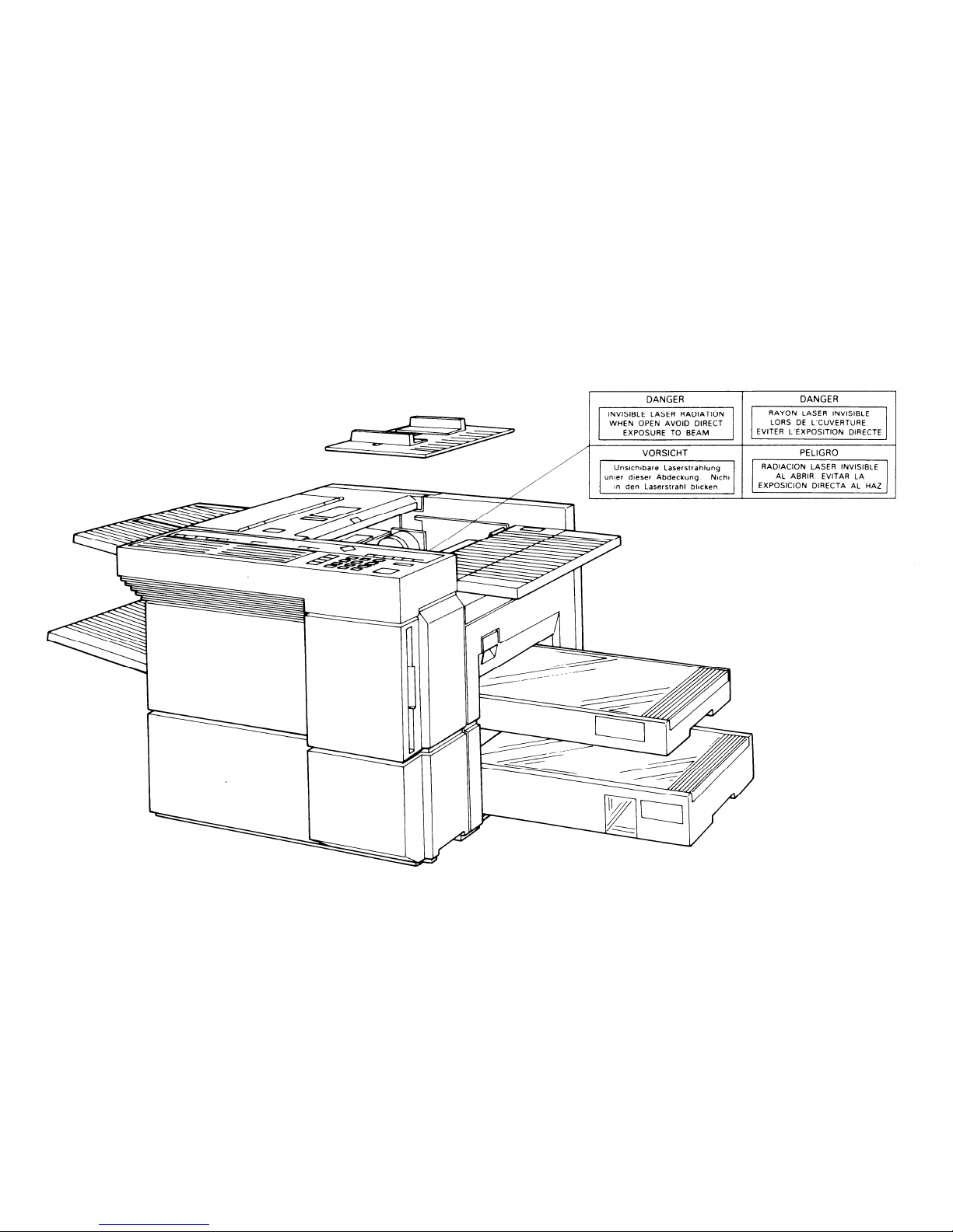
WARNING
THIS MACHINE CONTAINS A LASER BEAM GENERATOR. LASER
BEAMS CAN CAUSE PERMANENT EYE DAMAGE. DO NOT OPEN THE
LASER UNIT OR LOOK ALONG THE LASER BEAM PATH WHILE THE
MAIN POWER IS ON.
Page 2
Page 3

CONTENTS
SECTION 1. INSTALLATION
1-7-7. TTI #1 and TTl #2 - Function 85 . . . . 1-31
1-7-8. CSI - Function 86
1-1. Specifications . . . . . . . . . . . 1-1
1-2. Features . . . . . . . . . . . . . . 1-4
1-3. Installation Requirements . . . . . . 1-14
1-3-1. Environment . . . . . . . . . . . 1-14
1-3-2. Minimum Space Requirements . . . . 1-15
1-3-3. Power Requirements . . . . . . . . 1-16
1-4. Unpacking . . . . . . . . . . . . . 1-17
1-5. Accessory Check List . . . . . . . . 1-18
1-6. Installation Procedure . . . . . . . . 1-19
1-6-1. Master Unit . . . . . . . . . . . 1-19
1-6-2. Toner . . . . . . . . . . . . . . 1-20
1-6-3. Cassettes . . . . . . . . . . . . 1-22
1-6-4. Telephone . . . . . . . . . . . . 1-23
1-6-5. Cleaning Pad . . . . . . . . . . 1-23
1-6-6. Other Components . . . . . . . . 1-24
1-6-7. Power Connection . . . . . . . . 1-24
1-6-8. Hard Disk Initialization . . . . . . . 1-25
1-7. Initial Programming . . . . . . . . . 1-27
1-7-1. Country Code - Function 81 . . . . . 1-27
1-7-2. Fax Terminal’s Telephone Number -
Function 81 . . . . . . . . . . . 1-28
1-7-3. Transfer Station Number - Function 81 . 1-28
1-7-4. Polling ID Code - Function 82 . . . . 1-29
1-7-5. Confidential ID Code - Function 83 . . 1-29
1-7-6. RTI #1 and RTI #2 - Function 84 . . . 1-30
(W. Germany: Service Function 11) . . .1-31
1-7-9. Date and Time - Function 87 . . . . . 1-32
1-7-10. Telephone Line Type -
Service Function 12 . . . . . . . . 1-32
1-7-11. Reception Mode - Function 88 . . . . 1-33
1-8. Charge Control Parameter Programming . 1-34
1-9. Transporting the Machine . . . . . . . 1-39
SECTION 2. PROGRAMMING, TESTING,
AND PRINTING REPORTS
2-1. Operation Panel . . . . . . . .
2-2. User Level Programming . . . .
2-2-1. Function List . . . . . . . .
2-2-2. Others . . . . . . . . . . .
1. Multicopy Mode . . . . . . .
2. Keystroke Programs . . . . . .
2-3. Service Level Functions . . . . .
2-3-1. Function List . . . . . . . .
2-3-2. Entering and Exiting Service Mode
2-3-3. Bit Switches - Function 01 . . .
2-3-4. CCU - Function 02 . . . . . .
1. G3 CCU Test Mode . . . . . .
2. G3 Dump List 1 . . . . . . . .
3. G3 Dump List 2 . . . . . . . .
. .
2-1
. .
. 2-5
. . .
2-5
. . .
2-13
. . .
2-13
. . .
2-13
. .
. 2-14
. . .
2-14
. . .
2-18
. . .
2-19
. . .
2-20
. . .
2-20
. . .
2-22
. . .
2-22
Page 4

4. NCU Parameter Programming . . .
2-3-5. RAM - Function 03 . . . . . . .
1. RAM Read/Write . . . . . . . . .
2. Memory Dump List . . . . . . . .
3. Hard Disk Dump . . . . . . . . .
4. G3 CCU Handshake Logging Dump List
5. SPU Handshake Logging Dump List .
6. Error Code Logging Dump List . . .
7. Multicopy . . . . . . . . . . .
8. Counter Check . . . . . . . . .
9. Charge Control . . . . . . . . .
2-3-6. Service Station Number - Function 04
2-3-7. Counter Check - Function 05 . . .
2-3-8. Service Monitor Report Printing -
Function 06 . . . . . . . . . .
2-3-9. Parameter List Printing - Function 07
2-3-10. Serial Number Programming -
Function 08 . . . . . . . . . .
2-3-11. Tests - Function 09 . . . . . . .
1. Printer Tests . . . . . . . . . .
2. Fluorescent Lamp Lighting . . . . .
3. SPU Reset . . . . . . . . . . .
4. Operation Panel Test . . . . . . .
5. RAM Test . . . . . . . . . . .
6. DCR Test . . . . . . . . . . . .
7. ADF Mechanism Test . . . . . . .
8. SPU Test Menu . . . . . . . . .
9. Hard Disk Test . . . . . . . . .
2-3-12. Printer Status - Function 14 . . . .
2-3-13. Transmission Status Report -
Function 15 . . . . . . . . . .
.
2-23
.
2-24
.
2-24
.
2-25
.
2-26
2-27
.
2-27
.
2-28
.
2-28
.
2-29
.
2-29
.
2-30
.
2-30
.
2-31
.
2-31
.
2-32
.
2-32
.
2-32
.
2-33
.
2-34
.
2-34
.
2-35
.
2-36
.
2-36
.
2-37
.
2-37
.
2-38
.
2-40
2-3-14. G4 CCU Parameters - Function 16 . . 2-42
2-3-15. System Data List - Function 17 . . . . 2-42
2-3-16. Hard Disk Shipping Position -
Function 18 . . . . . . . . . . . 2-42
2-3-17. Dedicated Transmission Parameters . . 2-43
2-3-18. Back to Back Test . . . . . . . . . 2-46
2-3-19. Machine Reset . . . . . . . . . . 2-46
2-4. Bit Switches . . . . . . . . . . . . . 2-47
1. SCU - Factory Settings . . . . . . . . . 2-47
2. SCU - Bit Switch Tables . . . . . . . . . 2-49
3. G3 CCU - Factory Settings . . . . . . . 2-85
4. G3 CCU - Bit Switch Tables . . . . . . . 2-87
2-5. NCU Parameters . . . . . . . . . . . 2-112
2-6. Useful RAM Addresses . . . . . . . . 2-115
Redialling . . . . . . . . . . . . . . 2-115
Charge Control Parameters . . . . . . . . 2-115
Charge Control Report Printout Date . . . . 2-116
SECTION 3. REMOVAL AND
REPLACEMENT
3-1. Covers . . . . . . . . . . . . . . . 3-2
3-1-1. Lower Front Right, Lower Left, and
Upper Front Covers . . . . . . . . 3-2
3-1-2. Operation Panel . . . . . . . . . . 3-3
3-1-3. Upper Rear, Lower Rear, and
BSRU Covers . . . . . . . . . . . 3-4
3-1-4. Top Right and Top Covers . . . . . . 3-4
3-1-5. Rear Inner Cover, Right Inner Cover,
and Document Table . . . . . . . . 3-5
3-1-6. Front Inner Cover . . . . . . . . . 3-5
Page 5

3-2. ADF and Scanner . . . . . . . . . . 3-6
3-2-1. Document Feed and Pick-up Rollers . . 3-6
3-2-2. Document Separation Roller . . . . . 3-7
Separation Roller Adjustment . . . . . . 3-8
3-2-3. Fluorescent Lamp . . . . . . . . . 3-9
3-2-4. Fluorescent Lamp Driver . . . . . . 3-9
3-2-5. SBU . . . . . . . . . . . . . . 3-10
Scanner Adjustments . . . . . . . . . 3-11
3-2-6. Tx Motor Timing Belt Adjustment . . . 3-19
3-3. Printer - Charge . . . . . . . . . . . 3-20
3-3-1. Charge Corona Wire . . . . . . . . 3-20
3-4. Printer - Exposure . . . . . . . . . . 3-22
3-4-1. Second Cylindrical Lens . . . . . . 3-22
3-4-2. Pentagonal Mirror and Motor . . . . 3-23
3-4-3. Pentagonal Mirror Motor Driver
(SMDR) . . . . . . . . . . . . . 3-25
3-4-4. LSD . . . . . . . . . . . . . . 3-25
3-4-5. Laser Diode Unit . . . . . . . . . 3-26
3-5. Printer - Paper Feed . . . . . . . . . 3-27
3-5-1. Upper Paper Feed and Pick-up
Rollers . . . . . . . . . . . . . 3-27
3-5-2. Upper Paper Separation Roller and
Spring Clutch . . . . . . . . . . 3-28
3-5-3. Lower Paper Feed and Pick-up
Rollers . . . . . . . . . . . . . 3-29
3-5-4. Lower Paper Separation Roller . . . . 3-29
3-5-5. Master Belt Drive Motor Timing Belt
Adjustment . . . . . . . . . . . 3-30
3-5-6. Upper Paper Lift Mechanism
Adjustment . . . . . . . . . . . 3-30
3-6. Printing - Development . . . . . . . . 3-31
3-6-1. Development Unit . . . . . . . . . 3-31
3-6-2. Toner Metering Blade . . . . . . . . 3-31
3-6-3. Development Roller . . . . . . . . . 3-32
3-7. Printer - Transfer . . . . . . . . . . . 3-33
3-7-1. Transfer Corona Wire . . . . . . . . 3-33
3-7-2. Transfer Entrance Guide Plate
Adjustment . . . . . . . . . . . . 3-35
3-8. Printer - Fusing . . . . . . . . . . . 3-36
3-8-1. Fusing Unit . . . . . . . . . . . . 3-36
3-8-2. Thermostat . . . . . . . . . . . . 3-38
3-8-3. Fusing Lamp/Thermistor Assembly . . . 3-38
3-8-4. Hot Roller . . . . . . . . . . . . 3-39
3-8-5. Pressure Roller . . . . . . . . . . 3-40
3-8-6. Hot Roller Strippers . . . . . . . . . 3-40
3-9. Printer - Quenching . . . . . . . . . . 3-42
3-9-1. Quenching Lamp . . . . . . . . . 3-42
3-10. PUBs . . . . . . . . . . . . . . . 3-43
3-10-1. SPU, VPU, G3CCU, and Modem . . . 3-43
3-10-2. SCU and MBU . . . . . . . . . . 3-44
3-10-3. UIB . . . . . . . . . . . . . . 3-45
3-10-4. DSB . . . . . . . . . . . . . . 3-45
3-10-5. DRU . . . . . . . . . . . . . . 3-46
3-10-6. Power Pack . . . . . . . . . . . 3-46
3-10-7. PSU . . . . . . . . . . . . . . 3-48
3-10-8. Hard Disk . . . . . . . . . . . . 3-48
3-10-9. G3NCU . . . . . . . . . . . . . 3-50
3-10-10. LIB . . . . . . . . . . . . . . 3-50
3-10-11. BSRU . . . . . . . . . . . . . 3-51
3-11. Others
. . . . . . . . . . . . . . 3-51
3-11-1. Gas Spring Adjustment . . . . . . . 3-51
Page 6

SECTION 4. SERVICE TABLES
4-1. PM Table . . . . . . . . . . . . . 4-1
4-2. General Service Tables . . . . . . . . 4-3
4-2-1. Test Points . . . . . . . . . . . 4-3
4-2-2. Variable Resistors and Capacitors . . 4-5
4-2-3. Switches . . . . . . . . . . . . 4-5
4-2-4. LED Indicators . . . . . . . . . . 4-5
4-2-5. Jumpers . . . . . . . . . . . . 4-7
4-2-6. Special Tools and Lubricants . . . . 4-9
SECTION 5. TROUBLESHOOTING
5-1. Quality Checks . . . . . . . . . . . 5-1
1. Copy Quality . . . . . . . . . . . . 5-1
1. Copy Density . . . . . . . . . . . 5-2
2. Skew . . . . . . . . . . . . . . 5-2
3. Intelligibility . . . . . . . . . . . . 5-2
4. Copy Test . . . . . . . . . . . . 5-2
2. Operation Panel Display . . . . . . . . 5-3
3. Mechanism Test . . . . . . . . . . . 5-3
4. Communication Tests . . . . . . . . . 5-3
5-2. Copy Quality Troubleshooting . . . . . 5-4
5-3. Mechanical Problems . . . . . . . . 5-28
5-4. Service Call Conditions . . . . . . . 5-41
5-5. Error Codes . . . . . . . . . . . . 5-48
5-6. Hard Disk Troubleshooting Routines . . 5-64
1. Outline . . . . . . . . . . . . . . . 5-64
2. Entering and Exiting Hard Disk
Troubleshooting Mode . . . . . . . . 5-65
3. Functions . . . . . . . . . . . . . 5-65
3-1. System Start - Function 1 . . . . . . 5-65
3-2. Error Code Display - Function 2 . . . . 5-66
3-3. File Correction - Function 3 . . . . . 5-67
3-4. Random Read Test - Function 4 . . . . 5-67
3-5. All Read Test - Function 5 . . . . . . 5-67
3-6. Clear Address - Function 6 . . . . . 5-68
3-7. Clear Job - Function 7 . . . . . . . 5-68
3-8. Disk Format - Function 8 . . . . . . 5-69
4. Error Codes . . . . . . . . . . . . . 5-70
4-1. Power-up Error Codes . . . . . . . 5-70
4-2. Hard Disk Error Codes . . . . . . . 5-71
SECTION 6. OPTIONAL BAR CODE
READER
6-1. Accessory Check List . . . . . . . . . 6-1
6-2. Installation Procedure . . . . . . . . 6-2
SECTION 7. ELECTRICAL DATA
7-1. Point-to-point Diagram . . . . . . . . 7-1
7-2. Signal Tables . . . . . . . . . . . . 7-4
1. SCU . . . . . . . . . . . . . . . . 7-4
2. SPU . . . . . . . . . . . . . . . . 7-11
3. VPU . . . . . . . . . . . . . . . . 7-20
4. SBU . . . . . . . . . . . . . . . . 7-20
5. DRU . . . . . . . . . . . . . . . . 7-20
6. UIB . . . . . . . . . . . . . . . . 7-22
7. DSB . . . . . . . . . . . . . . . . 7-24
8. LIB . . . . . . . . . . . . . . . . . 7-25
9. OPU . . . . . . . . . . . . . . . . 7-26
Page 7

10. PSU
. . . . . . . . . . . . . . . 7-26
11. G3 CCU . . . . . . . . . . . . .7-28
12. G3 NCU . . . . . . . . . . . . . 7-30
13. BSRU . . . . . . . . . . . . . . 7-31
7-3. Block Diagrams . . . . . . . . . . . 7-32
1. Overall Machine Control . . . . . . . . 7-32
2. Video Data Path . . . . . . . . . . . 7-37
3. Power Distribution . . . . . . . . . . 7-40
4. Scanner . . . . . . . . . . . . . . 7-43
5. Communication Control . . . . . . . . 7-46
6. Printer . . . . . . . . . . . . . . . 7-47
7-4. Electrical Component Layout . . . . . 7-51
7-5. Timing Charts . . . . . . . . . . . 7-55
APPENDIX
A. Glossary . . . . . . . . . . . . . . A-1
Page 8

SECTION 1
Page 9

SECTION 1. INSTALLATION
1-1. Specifications . . . . . . . . . . . 1-1
1-2. Features . . . . . . . . . . . . . . 1-4
1-3. Installation Requirements . . . . . . 1-14
1-3-1. Environment . . . . . . . . . . . 1-14
1-3-2. Minimum Space Requirements . . . . 1-15
1-3-3. Power Requirements . . . . . . . . 1-16
1-4. Unpacking . . . . . . . . . . . . . 1-17
1-5. Accessory Check List . . . . . . . . 1-18
1-6. Installation Procedure . . . . . . . . 1-19
1-6-1. Master Unit . . . . . . . . . . . 1-19
1-6-2. Toner . . . . . . . . . . . . . . 1-20
1-6-3. Cassettes . . . . . . . . . . . . 1-22
1-6-4. Telephone . . . . . . . . . . . . 1-23
1-6-5. Cleaning Pad . . . . . . . . . . 1-23
1-6-6. Other Components . . . . . . . . 1-24
1-6-7. Power Connection . . . . . . . . 1-24
1-6-8. Hard Disk Initialization . . . . . . . 1-25
1-7. Initial Programming . . . . . . . . . 1-27
1-7-1. Country Code - Function 81 . . . . . 1-27
1-7-2. Fax Terminal’s Telephone Number -
Function 81 . . . . . . . . . . . . 1-28
1-7-3. Transfer Station Number - Function 81 . 1-28
1-7-4. Polling ID Code - Function 82 . . . . . 1-29
1-7-5. Confidential ID Code - Function 83 . . . 1-29
1-7-6. RTI #1 and RTI #2 - Function 84 . . . 1-30
1-7-7. TTl #1 and TTl #2 - Function 85 . . . . 1-31
1-7-8. CSI - Function 86
(W. Germany: Service Function 11) . . . 1-31
1-7-9. Date and Time - Function 87 . . . . . 1-32
1-7-10. Telephone Line Type -
Service Function 12 . . . . . . . . 1-32
1-7-11. Reception Mode - Function 88 . . . . 1-33
1-8. Charge Control Parameter Programming . 1-34
1-9. Transporting the Machine . . . . . . . 1-39
Page 10

1-1. Specifications
Type
Circuit
Connection
Document size
Length:
Width:
Thickness:
Weight:
Document feed
ADF capacity
Scanning method
Maximum scan width
Console-type transceiver
PSTN, PABX
Direct couple
Auto Doc. Feed Manual Doc. Feed
105 - 600 mm
105 - 1,200 mm
[4.13 - 23.6 ins]
[4.13 - 47.2 ins]
Unlimited length is available.
User must support documents longer than
420 mm [16.5 ins]
105 - 304 mm
[4.1 - 12.0 ins]
0.05 - 0.2 mm
0.04 - 0.4 mm
[2 - 8 mils]
[2 - 16 mils]
About 50 to 80 g/m
2
About 40 to 120 g/m
2
Automatic feed, face down
30 sheets (using 75 g/m2 paper)
Flat bed, with CCD
304 mm [12.0 ins]
1-1
Page 11

Scan resolution
Main scan: Standard, Detail - 200 dpi (7.87 dots/mm)
Super Fine - 400 dpi (15.75 dots/mm)
Options: 8, 16 dots/mm
Sub scan:
Standard - 100 dpi (3.94 lines/mm)
Detail - 200 dpi (7.877 lines/mm)
Super Fine - 400 dpi (15.75 lines/mm)
Options: 3.85, 7.7, 15.4 lines/mm
300 x 300 dpi (11.8 x 11.8 dots per mm) is also
available after programming a user function key
(tx mode only).
Memory capacity
Hard disk, 18 M capacity after formatting
Compression
MH, MR, EFC, MMR, New EFC
Modulation
V.29, V.27ter, V.21, AM-PM-VSB, QAM
Protocol
Groups 2, and 3 with ECM; autocompatibility
Group 4 interface option available
Data rate
9600/7200/4800/2400 bps; automatic fallback
Transmission time
10 s for a CClTT #1 document (Slerexe letter)
using standard resolution
Printing system
Laser printing, plain paper, dry toner
1-2
Page 12

Paper size
Letter [8.5 x 11”]
Legal [8.5 x 14“]
B4
A4
Maximum printout width
250 mm [9.8 ins]
Maximum printer resolution Main scan - 400 dots/inch [15.75 dots/mm]
Sub scan - 400 lines/inch [15.75 dots/mm]
Power supply
220 Vac + 22/-33 V; 50/60 Hz +/- 1 Hz
240 Vac + 24/-36 V; 50/60 Hz +/- 1 Hz
Power consumption (W)
Standby: 90
Transmit:
140
Receive:
900
Copying:
900
Operating Environment
Temperature: 5 - 35 degC
[41 - 95 degF]
Humidity: 10 - 85 %Rh
Dimensions (W x D x H) 475 x 603 x 388 (mm)
18.7 x 23.7 x 15.3 (inches)
Excludes trays and cassette
Weight
55 kg [121 Ibs]
1-3
Page 13

1-2. Features
Equipment
Availability
Default
Built-in handset
x
Connection for external tel.
o
Base cabinet
o
KEY
Manual feed for thick originals
o o = Used
Monitor speaker
o x = Not used
Microphone
o
Speakerphone
x
o
Remaining memory indicator (Function mode) o
Video Processing
Availability
Default
Features
Contrast (Lighten, Normal, Darken)
o
See Note 1.
Resolution (Std, Dtl, Super Fine)
o
Halftone
o
MTF (selectable by service)
x
Reduction - A3 to A4
o
o
- A3 to B4
o
o
- B4 to A4
o
Smoothing (rx) - 200 x 100 to 400 x 400
o o
- 200 x 200 to 400 x 400
o o
1-4
Page 14

Communication Features -
Availability
Default
Automatic
Scanning and storing during tx or rx
o
Redialling
o
Four redials
G2, G3 compatibility
o
Automatic fallback o
Confidential/substitute reception
o
Confidential: Not used in W. Germany
Page retransmission from memory
o
Communication Features -
Availability
Default
User Selectable
Auto/Manual reception
o
On hook dial
x
Speed Dial
2,000
Quick Dial Keys
50
Keystroke programs (See Note 2)
50
Groups
32
- max no. of addresses/group
200
- max no. of full tel nos. in all groups
1,020
Alternative destination
o
(with Quick and Speed Dial only)
Department code
o
Batch numbering
o
MMR/EFC disabling option
o
ECM disabling option
o (Not available in machines from factory for W. Germany)
Turnaround polling
o
Continued on the next page
1-5
Page 15

Communication Features -
Availability
Default
User Selectable (continued)
Auto-reduction override option
o
Immediate redial
o
Auto-answer delay time
x
Hold
x
Voice Request
o
Automatic Voice Message
o
Not used in W. Germany
Communication Features -
Availability
Default
Service Selectable
Closed network
o x
MV1200 compatibility
x
Short preamble
o x
Well log (tx)
o x
Protection against bad connections
x
EFC
o
Tx - on, Rx - on
PSTN access through PBX
o x
Polling ID code security
x
ECM
o
o
Operator restriction by department code
o
x
Resol’n stepdown override option
x
Conf’l password override option
o
1-6
Page 16
Special Communication
Availability
Default
Features
Transmission from memory
o
- immediate
o
- send later
o
- max no. of addresses/file
200
- max no. of files
500
- max no. of addresses over all files
1,020
See Note 3 (p. 1-13).
Send Later
o
Confidential Transmission
o
Not used in W. Germany
- immediate
o
Not used in W. Germany
- send later
o
Not used in W. Germany
- broadcasting
o
Not used in W. Germany
- remote password override
o
Not used in W. Germany
Transfer Request
o
Not used in W. Germany
- max no. of broadcasters
200
Not used in W. Germany
- max no. of end receivers
30
Not used in W. Germany
- stored ID override
o
- from memory
o
- 1 day/1 polling memory duration option
o
1 day
Continued on the next page
1-7
Page 17

Special Communication
Availability
Default
Features (Continued)
Polling Reception
o
- free/secured option
o
- stored ID override
o
- poll later: max no. of files
500
: max addresses/file
200
: max addresses overall
1,020 See Note 3 (p. 1-13).
Batch transmission
o
o
Forwarding
o
Transmission deadline
o
Notify
x
Other Features
Availability
Default
Multicopy: max 99 copies/original
o
Copy mode
o
User function keys
o
See Note 2.
Dialled tel. number check
o
Auto note
o
A3-width transmission
o
LCD brightness adjustment
o
Night timer
o
Printing out a memory file
o
1-8
Page 18

Reports - Automatic
Availability
Default
Journal (optional)
o o
Charge Control Report
o
W. Germany/Italy: o, Others: x
Tx Result Report (optional)
o o
Error Report (optional)
o x
Transfer Result Report
o
Not used in W. Germany
Mode Change Report
o
W. Germany: o, Others: x
Polling File List
o
Memory Report (optional)
o
x
Power Failure Report
o
Polling Result Report (optional)
o o
Polling Reserve Report (optional)
o o
Polling Clear Report (optional)
o o
Reports - User
Availability
Default
Journal
o
Charge Control Report
o
W. Germany/Italy: o, Others: x
Telephone List (includes Group List)
o
Polling File List
o
SAF File List
o
User Function List
o
Department Code List
o
Transmission Status Report
o
Program List
o
1-9
Page 19

Reports - Service
Availability
Default
Group 3 Protocol Dump Lists
o
Auto Service Call
o
System Parameter List
o
RAM Address Dump
o
Hard Disk Dump
o
Handshake Logging Dump
o
(For G3CCU and SPU)
Error Code Logging Dump
o
Transmission Status Report
o
System Data List
o
Service Monitor Report
o
User Programming
Availability
Default
Clock
o
Auto/Manual Rx setting
o
Auto
Tx/Rx page counter display
o
Sheet feed counter display
o
Batch number on/off
o
x
Department code on/off
o
x
Speaker volume adjustment
o
Continued on the next page
1-10
Page 20

User Programming
Availability
Default
(Continued)
Automatic Voice Message recording
o
Automatic Voice Message playback
o
Automatic Voice Message on/off
o o
Quick Dial/Group programming
o
Polling ID code
o
RTI/TTI/CSl
o
See Note 4.
RTI #2, TTl #2
o
Direct entry of labels and identifiers
o
Changing the contents of a file
o
Polling file clearance
o
Memory file clearance
o
Own telephone number
o
Telephone line type (See Note 4.)
U. K.: o, Others: x
Pulse
TTl on/off
o o
ECM on/off
o
Substitute reception on/off
x
Forwarding
o
Stamp on/off
o
x
Password
o
Rx mode switching timer
x
Master unit counter reset
o
Keystroke programs
o
ECM on/off is not available in machines shipped for W. Germany. It can be made available by
bit switch adjustment.
1-11
Page 21

Service Mode and
Availability
Default
System Tests
Dedicated Tx Parameters
o
Printout of all memory files
x
Bit switches
o
RAM rewriting - to local fax only
o
Error code display
o
Printer status display
o
Counter check and rewrite
o
Chequered mark on 1st page on/off
o
o
Number of copies per printout
o
1
Rx fax printout in reverse page order
o x
Serial number programming
o
NCU parameters
o
Modem and DTMF tone tests
o
Operation panel test
o
Fluorescent lamp lighting
o
Back-to-back test
o
RAM tests
o
Hard disk tests and maintenance
o
SPU tests
o
DCR tests
o
SPU reset
o
Printer test patterns
o
Maximum address limitation
x
ADF/printer mechanism tests
o
1-12
Page 22

Notes
1.
2.
3.
4.
Contrast can also be selected in halftone mode.
The keystroke programs are stored in Quick Dial Keys, so the no. of programmed Quick Dial Keys
plus the no. of programs plus the number of user function keys programmed as Quick Dial Keys cannot exceed 50 (user function keys can also be stored as Quick Dial Keys if more than 5 keys are
needed).
The number of addresses programmed for polling reception and for memory transmission, when combined, cannot exceed 1,020.
CSI is a service function in W. Germany.
machines for the U.S.A. and the U. K..
Telephone line type selection is a service mode in all except
1-13
Page 23
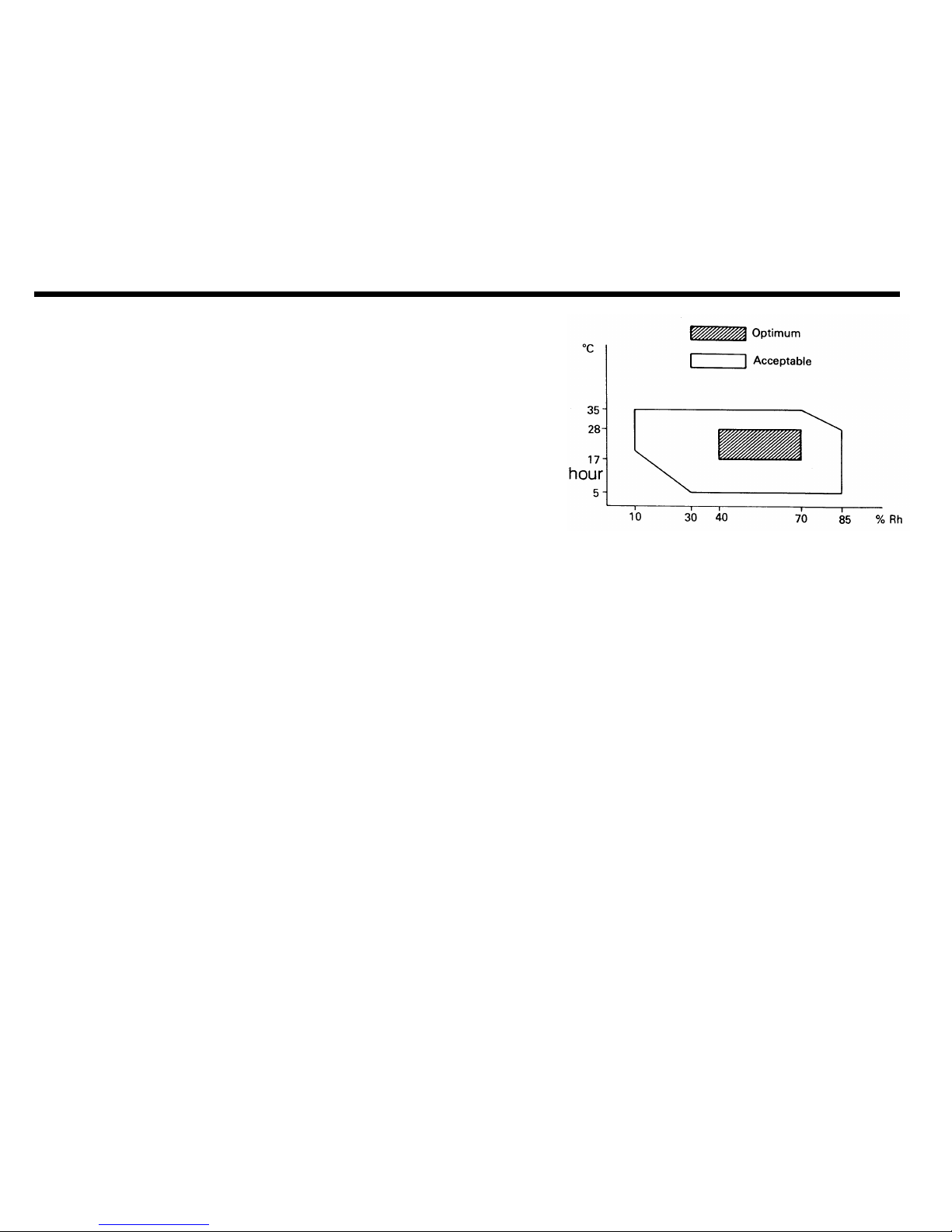
1-3. Installation Requirements
1-3-1. Environment
Temperature range: 17 to 28 degrees C [63 to 82 degrees F]
Humidity range: 40 to 70 %Rh - no condensation
Ventilation: Room air should turn over at least three times per
Ambient dust: Less than 0.15 mg/m3 [4 x 10¯³ oz/yd3]
Avoid placing the machine where it will be exposed to corrosive gases.
Place the machine on a strong and level base.
Place the machine where it will be:
• Not subject to direct sunlight
• Not subject to strong vibration
• Condensation free
• Away from other electronic equipment, to avoid interference
• Away from heaters and air conditioners, to avoid sudden temperature changes.
1-14
Page 24
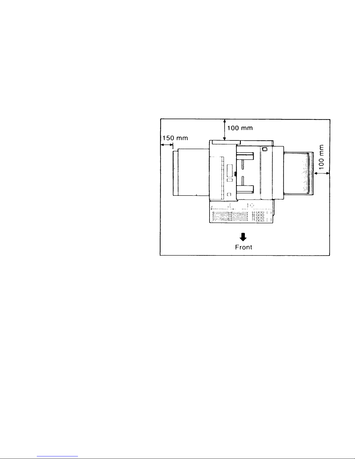
1-3-2. Minimum Space Requirements
1-15
Page 25

1-3-3. Power Requirements
Voltage
• 220 Vac + 22/-33 V, or 240 Vac + 24/-36 V, 50/60 Hz, capable of supplying more than 10 A
Power Outlet
• Must be properly grounded
• If possible, do not connect other equipment to the same outlet.
• Insert the plug securely.
1-16
Page 26
1.
2.
3.
4.
5.
6.
7.
8.
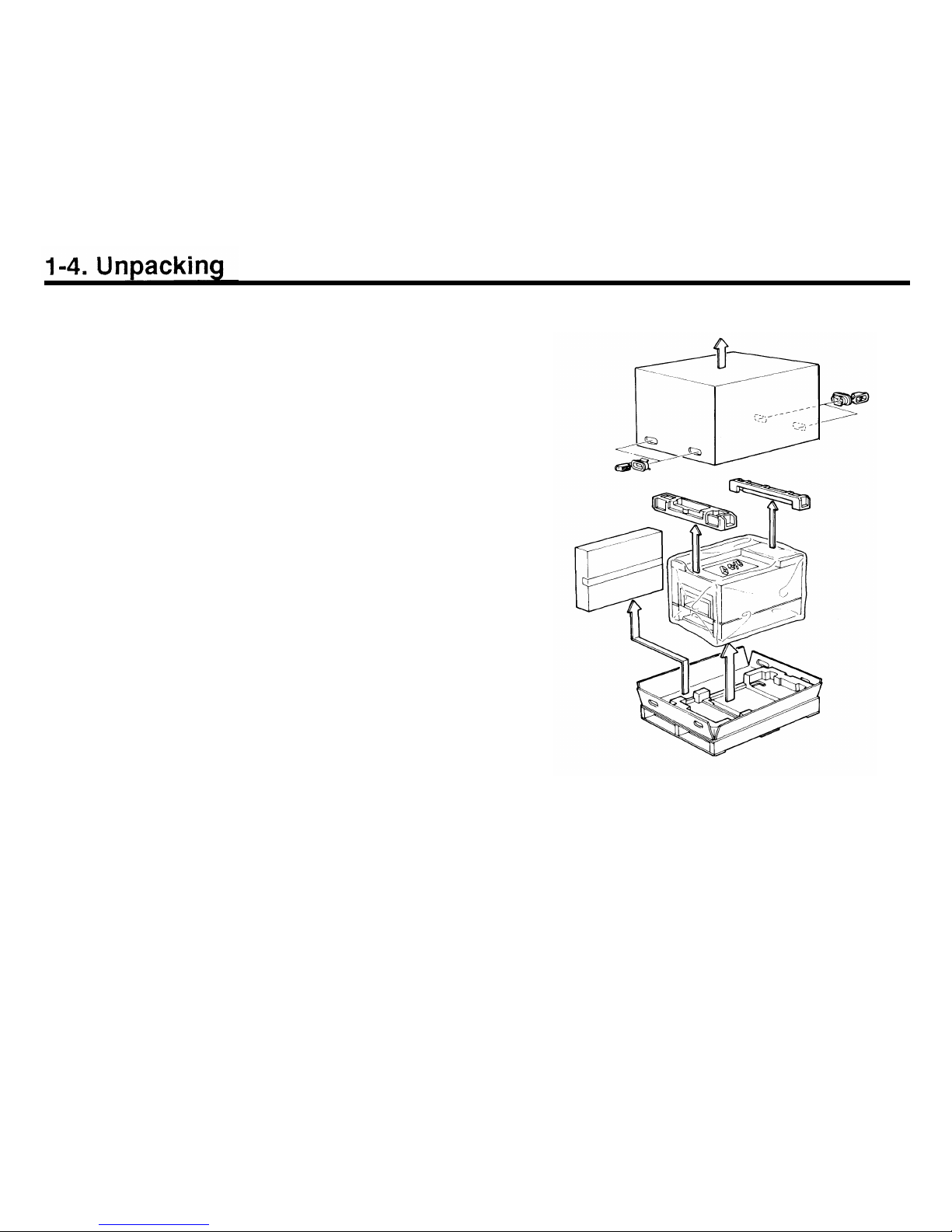
Remove the packing clips from the carton.
Remove the two cushion blocks.
Take the accessories box and the machine out of the
carton.
Open the vinyl envelope and take out the machine.
Peel off the packing tapes from the outside of the
machine.
Inside the machine, remove the packing tapes from
the development unit, registration roller, jam removal
lever (lower cassette), and the upper and lower paper
lift arms.
Open the lower front cover and remove the cushion
block from inside the lower cassette.
Place the machine on a table.
Caution: The table must be horizontally level within 2
degrees.
1-17
Page 27

1-5. Accessory Check List
Open the accessories box and check that the following items are present.
1. Vinyl Gloves
2. Plastic Bag
3. Toner Cartridges
4. Cleaning Pad
5. Cassettes
(upper and lower)
6. Paper Size Actuators
7. Paper Size Decals
8. Sub-document Table
9. Document Tray
10. Copy Tray
11. Quick Dial Labels
12. User Function Key Cards
13. User Function Label
14. Speed Dial Address
Decal
15. Operator’s Manual
16. Stamp Ink
17. Pack of Paper
18. Power Cord
19. Master Unit
20. NECR
21. Scanner Pick-up Roller
22. Microphone
1 set
1
2
1
2
6
2 sets
1
1
1
2
2
1
5 pcs
1
1
1
1
1
1
1
1
1-18
Page 28

1-18a
Page 29
1-6. Installation Procedure
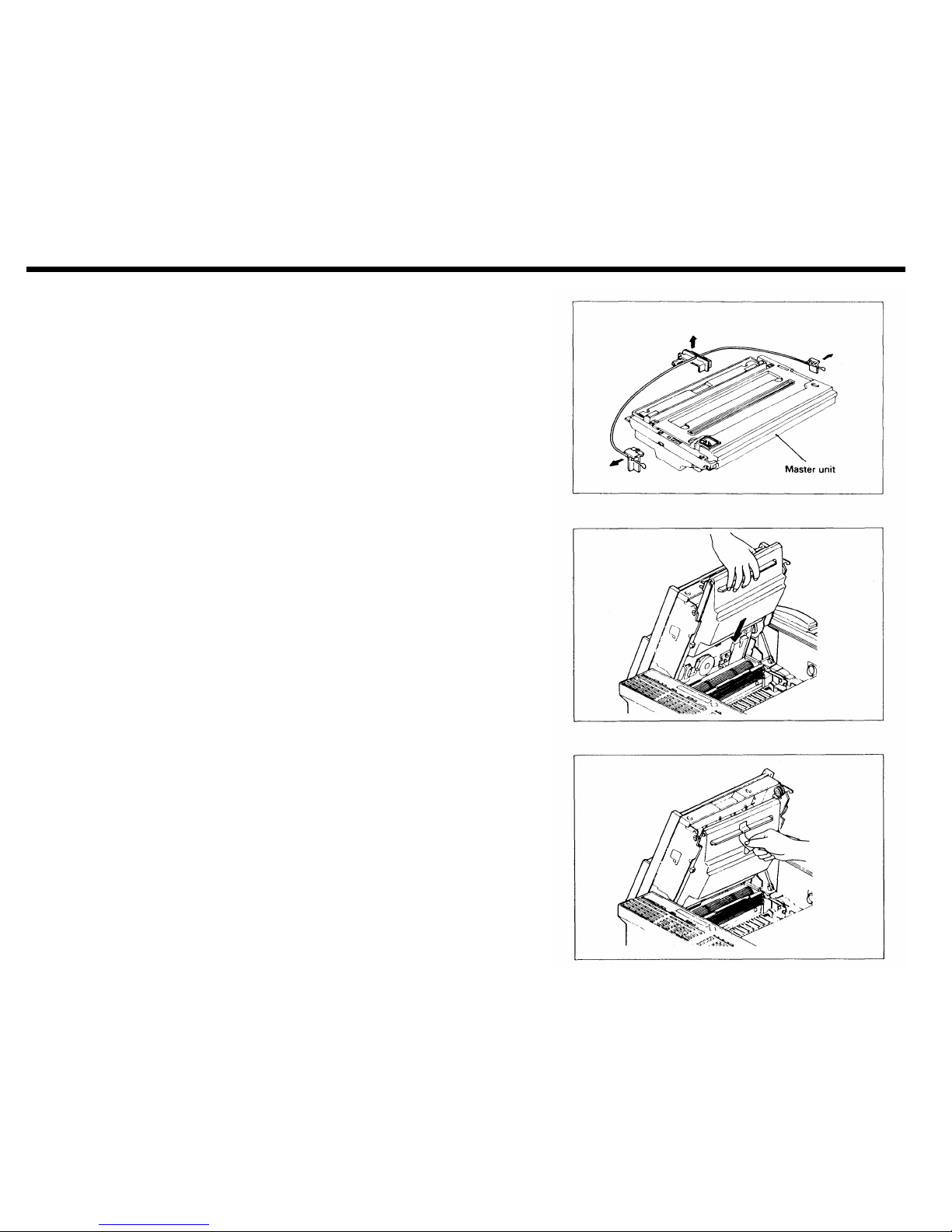
1-6-1. Master Unit
1.
2.
3.
4.
Remove the three plastic wedges from the master unit.
Caution: Do not remove the green plastic cover.
Open the upper unit and insert the master unit into the
machine with the green plastic cover facing out.
Take off the green plastic cover.
Note: Do not touch the master belt surface (purple
sheet), and do not expose it to direct sunlight
or bright light.
Close the upper unit.
1-19
Page 30

1-6-2. Toner
1. Open the right cover.
2. Shake a toner cartridge well.
3. Remove the cartridge crank from the cartridge.
4. Set the pins on the toner cartridge into the slots on
the development unit.
5. Rotate the cartridge up until it snaps into position.
1-20
Page 31

6.
7.
8.
9.
Fit the cartridge crank (or winding lever) onto the pin
on the bottom left of the cartridge.
Turn the crank (or winding lever) clockwise to strip off
the cartridge seal, until you see the yellow band. Then
remove the cartridge crank (or winding lever).
CAUTION:
If the yellow band is not showing, the plastic strip could become caught in the toner
mixing mechanism, leading to machine
damage.
Remove the empty toner cartridge and install another
(refer to steps 2 to 7). Place the empty cartridge in the
disposal bag.
Note: When adding toner during normal operation,
only one cartridge should be replaced.
Close the right cover.
1-21
Page 32

1-6-3. Cassettes
Remove the tape from the trays in the upper and lower
cassettes.
Put some copy paper in the cassettes, attach the cas-
sette top covers, and install the cassettes.
Note: The cassettes are set up for Letter-size paper. If
1.
2.
3.
4.
5.
6.
the user wishes to use a different paper-size than
this, modify the cassette(s) as follows.
Move the rear and side fences to the appropriate positions.
Attach the appropriate paper size decal to the tray.
Change the paper size actuator to the appropriate
one.
Add paper.
Attach the top cover.
Install the cassette.
1-22
Page 33

1-6-4. Telephone
1. If you connect a telephone to the rear of the machine,
make sure that the type of dialling signal generated by
the telephone matches the type of signal that the local
exchange accepts (pulse or tone dialing).
1-6-5. Cleaning Pad
1.
2.
3.
Open the copy exit cover.
Install the cleaning pad (4 screws).
Close the copy exit cover.
1-23
Page 34

1-6-6. Other Components
1.
Attach the function label.
2. Attach the copy tray.
3. Attach the document tray.
1-6-7. Power Connection
1.
2.
3.
4.
Connect the power cord to a supply of the type
specified on page 1-16.
Voltage must not fluctuate more than the limits
specified on page 1-16.
Make sure that the plug is firmly inserted into the out-
let.
A dedicated circuit is recommended.
1-24
Page 35

1-6-8. Hard Disk Initialization
1. Switch the main power on.
If an error message is displayed at this time, there is a
problem with the hard disk. See page 5-70 (Power-up
Error Codes).
2. Within 3 seconds of switching the power on, press
Function, then *, then #. An error message is displayed. However, there is no problem unless an error
code is displayed in the central line of the LCD. If an
error message is displayed at this time, there is a
problem with the hard disk. See page 5-70 (Power-up
Error Codes).
3. Press Function, then *, then # once more.
4. The hard disk troubleshooting menu is displayed.
Press 8 then Yes.
1-25
Page 36

5. When ENTER PASSWORD is displayed, enter 1988, then press Yes.
6. When “Initialize System? Y/N” is displayed, press Yes.
7. Enter the bad spot information listed on the decal inside the lower front cover.
The format of data on the label is shown in the following example:
CYL HD BYTE
319
1 8132
In the above example, press 31918132.
Press the down arrow on the scroll key to enter the next bad spot.
If there are no more bad spots, press Yes.
Note: Bad spots that develop after shipment from the factory and during machine use are automat-
ically discovered and stored in the system RAM when the following conditions occur. Such
areas will be avoided when storing messages and parameters to the disk.
• During formatting, either at installation or at any other time
• During use, if an error occurs, the machine will avoid the area of the disk that caused the
error. In this case, the memory capacity display will read less than 100%, even if there are
no fax messages on the hard disk.
8. “Initialize System Y/N’ is displayed again. Press Yes to format the hard disk.
9. After formatting, the machine automatically enters initial programming mode. After doing the initial
programming (see section 1-7), press Function to return the machine to standby.
10. Program the CSI (section 1-7-8), telephone line type (section 1-7-10), charge control parameters (section 1-8), serial number (section 2-3-10) and the service station telephone number (section 2-3-6).
1-26
Page 37

1-7. Initial Programming
After installation, the following items should be programmed. They can all be programmed by the user. They
can all be programmed in sequence by using Function 81. In this manual, each individual procedure will be explained.
1-7-1. Country Code - Function 81
Program the international dial access code then the country code.
1.
2.
3.
4.
5.
Make sure that the machine is in standby mode.
Press Function, then enter 80, then enter 2222.
Enter 81.
Enter the international dial access code then the country code. For example, enter 00144 (Internation-
al code
= 001, country code = 44).
To correct a mistake, press Clear (erases the last digit or the cursor digit), or No (erases the entire
code).
Press Yes to store the displayed codes, then press Function to return the machine to standby mode.
1-27
Page 38

1-7-2. Fax Terminal’s Telephone Number - Function 81
If this number is not programmed, Transfer Request is impossible.
1.
2.
3.
4.
5.
Make sure that the machine is in standby mode.
Press Function, then enter 80, then enter 2222.
Enter 81, then press Yes.
Enter the fax terminal’s telephone number. Place a pause after the area code, using the Pause key.
To correct a mistake, press Clear (erases the last digit or the cursor digit), or No (erases the entire
number).
Press Yes to store the displayed number, then press Function to return the machine to standby mode.
1-7-3. Transfer Station Number - Function 81
If this machine will be used as the first stage in a two-step transfer operation, the number of the terminal
acting as the second stage must be stored here. This function is only used in Group 4 communications.
1.
2.
3.
4.
5.
Make sure that the machine is in standby mode.
Press Function, then enter 80, then enter 2222.
Enter 81, then press Yes twice.
Enter the transfer station number.
To correct a mistake, press Clear (erases the last digit or the cursor digit), or No (erases the entire
number).
Press Yes to store the displayed number, then press Function to return the machine to standby mode.
1-28
Page 39

1-7-4. Polling ID Code - Function 82
This four-digit code is necessary for secured polling, closed network communication, and transfer re-
quest. All terminals in these types of communications must decide on the same ID code or the
communication will fail.
1. Make sure that the machine is in standby mode.
2. Press Function, then enter 80, then enter 2222.
3. Enter 82.
4. Enter the code. Do not use 0000 or FFFF.
5. Press Yes to store the displayed code, then press Function to return the machine to standby mode.
1-7-5. Confidential ID Code - Function 83
This ID code is used to print confidential messages stored on the hard disk.
This function is not used in W. Germany.
1. Make sure that the machine is in standby mode.
2. Press Function, then enter 80, then enter 2222.
3. Enter 83.
4. Enter the code.
5. Press Yes to store the displayed code, then press Function to return the machine to standby mode.
1-29
Page 40

1-7-6. RTI #1 and RTI #2 - Function 84
The RTI (Remote Terminal Identification) identifies your terminal at the other end. It is displayed on the
operation panel at the other end during communication. RTI #1 will normally be used. However, when
you program a number as a Speed Dial or Quick Dial, you can select either RTI #1 or RTI #2 for use
when sending to that terminal. Note that if RTI #1 is selected, TTI #1 will also be used, and if RTI #2 is
selected, TTl #2 will be used.
Each RTI can have up to 20 characters.
1.
2.
3.
4.
5.
6.
7.
Make sure that the machine is in standby mode.
Press Function, then enter 80, then enter 2222.
Enter 84.
Type in RTI #1. For numbers use the ten-key pad. For letters and punctuation marks, use the Quick
Dial keys. For a space, use Quick Dial 27.
To correct a mistake, press Clear (erases the last letter or the cursor letter), or No (erases the entire
name).
Press Yes to store the displayed RTI.
Type in RTI #2 in the same way, then press Yes to store it.
Press Function to return the machine to standby mode.
1-30
Page 41

1-7-7. TTI #1 and TTl #2 - Function 85
The TTl (Transmit Terminal Identification) is another label which identifies you at the other end. It is
printed at the other end on the top line of each page that you send. Each TTl can have up to 32 charac-
ters.
1. Make sure that the machine is in standby mode.
2. Press Function, then enter 80, then enter 2222, then enter 85.
3. Either:
•
If RTI #1 can be easily added to or edited to make the TTl #1, then press 2. (Then, if TTl #1 is the
same as RTI #1, press Yes and go to step 5.) To edit RTI #1, press 1 then go to step 4.
•
To enter a TTl, press 1 and go to step 4.
4. Enter TTl #1 as explained for RTI #1 (page 1-30). Then press Yes twice to store it.
5. Repeat steps 3 and 4 for TTI #2.
6. Press Function to return the machine to standby mode.
1-7-8. CSI - Function 86 (W. Germany: Service Function 11)
In W. Germany, this is service function 11. The CSI (Called Subscriber Identification) is used instead of
the RTI when the machine communicates with another maker’s facsimile terminal.
1. Make sure that the machine is in standby mode.
2. W. Germany: Enter the service mode as shown on page 2-18, then enter 11.
Other areas: Press Function, then enter 80, then enter 2222 then 86.
3. Enter the CSI. It is best to use the fax machine’s telephone number.
To correct a mistake, press Clear (erases the last digit), or No (erases the entire CSI).
4. Press Yes to store the displayed CSI, then press Function to return the machine to standby mode.
1-31
Page 42

1-7-9. Date and Time - Function 87
1. Make sure that the machine is in standby mode.
2. Press Function, then enter 80, then enter 2222.
3. Enter 87.
4. Use the left and right arrows of the scroll key to highlight the parts of the display that need changing,
and type in the new values at the ten key pad. For the month, press the down arrow on the scroll key
until the correct month appears. The time is typed in using the 24 hour format.
5. Press Yes to store the displayed date and time, then press Function to return the machine to standby
mode.
1-7-10. Telephone Line Type - Service Function 12 (U. K.: User Function 88)
This must match the dialling method accepted by the local exchange, or the machine will not be able to
dial.
1. Make sure that the machine is in standby mode.
2. U.K. and U. S.A.: Press Function, enter 80, then 2222, then 88.
Other areas: Enter the service mode as shown on page 2-18, then enter 12.
3. Use the left and right arrows of the scroll key to highlight the required setting.
4. Press Function to store the displayed setting and return the machine to standby mode.
1-32
Page 43

1-7-11. Reception Mode - Function 88
Select either Automatic Reception (the machine receives fax messages automatically without intervention
by the user) or Manual Reception (the user must be present by the machine when a fax message comes
in).
1.
2.
3.
4.
5.
1-7-12.
1.
2.
3.
4.
5.
1-7-13.
1.
2.
3.
4.
Make sure that the machine is in standby mode.
Press Function, then enter 80, then enter 2222.
Enter 88, then press Yes.
Use the left and right arrows of the scroll key to highlight the required setting.
Press Function to store the displayed setting and return the machine to standby mode.
Service Station Number - Service Function 04
Make sure that the machine is in standby mode.
Enter the service mode as shown on page 2-18, then enter 04.
Type in the service station telephone number. Press Yes to store the number.
Type in the second service station number. Press Yes to store the number.
Press Function to return to standby mode.
Serial Number Programming - Service Function 08
Make sure that the machine is in standby mode.
Enter the service mode as shown on page 2-18, then enter 08.
Type in the serial number. Press Yes to store the number.
Press Function to return to standby mode.
1-33
Page 44

1-8. Charge Control Parameter Programming
Using charge control, the user can check the cost of each call made with the machine. Charge control is only
available on numbers that have been stored using Quick Dial, Speed Dial, Speed Dial # 1, or Speed Dial # 2,
and is controlled using option 7 of the option menu for Quick/Speed Dial programming.
Using option 7, the user selects the time per unit cost for a particular charge period (see Charge Control
Codes, M to P, below); the user selects the correct value for the address from a menu of values stored by the
service technician.
Figures for West Germany and Italy have been programmed in the software. For other areas, a service tech-
nician must enter the following values in advance:
• Number of periods in the day having different rates (maximum 4 charge periods)
• Number of zones, in which the charge varies with distance (maximum 7 charge zones)
• Basic charge unit
• The charge periods
• The time per basic charge unit for each zone, during each period
The procedure is as follows.
1. Enter the service mode. See page 2-18.
2. When the service mode menu is displayed, enter 03 at the ten-key pad.
3. When the RAM menu is displayed, press 9. A table of 80 two-digit codes is displayed. An example is
shown below.
0207 302E 3233 2044
4D00 FFFF 0800 1800
1-34
Page 45

4.
5.
6.
7.
Only two rows (16 codes) are visible at once. More rows in the charge control table can be seen by pressing the down arrow on the cursor key.
Press the left and right arrows on the cursor key to highlight the number to be changed.
Type in any changes as required. The meanings of the codes are explained after this procedure.
Press Yes when all numbers have been entered.
Press Function if all service mode operations have been finished.
Charge Control Codes
To illustrate how to program the charge control parameters, let us represent the table of codes in the following
manner. Remember that only two rows are visible at once. Following this explanation, an example will be
given.
AB
CD
EF GH
IJ
KL MN
OP
QR
ST
UV
WX
YZ
ab cd
ef
gh
ij
kl
mn
op qr
st
uv
wx
ab
cd
ef
gh
ij
kl
mn
op
qr
st
uv
yz
A: This shows the number of different charge periods in the day. For example, if there are only two, enter 02.
1-35
Page 46

B: This shows the number of charge zones. For example, if there are seven zones, enter 07.
C to L: These 10 ASCII codes show the basic charge unit. A table of ASCII codes follows at the end of this
section. For example, to enter ’0.23 DM’ (0.23 German marks), enter 30 2E 32 33 20 44 4D 00 FF FF. ’00’ is
entered at the end, after the ’M’ in the example, and ’FF’ is added to make the total up to 10 ASCII codes.
M to X: These show the charge periods. Up to four periods can be used. Enter all the periods except one; the
missing one is deduced from the three entered periods. For example, if there are two periods, one from 08:00
to 18:00, and the other from 18:00 to 08:00, enter 08 00 18 00 in M, N, O, P, then enter 00 in codes Q to X.
The machine will assume that there is another period from 18:00 to 08:00 to fill up the 24 hour day.
Note: When the customer enters the time per basic charge unit for a destination with Quick/Speed Dial
option 7, the choices displayed will be based on the period entered in codes M to P. Therefore,
in most cases, this should represent the peak rate, or the period in which the machine is most
often used. Consult the user about which period to enter here.
The rest of the
codes are a table of times allowed per basic charge unit, for each zone, and for each period.
The column YZ
to
uv shows the times allowed for calling during the period programmed in codes M to P, for
up to 7 zones. These are the values from which the user selects using Quick/Speed Dial option 7.
The column ab to
wx shows the times per charge unit during the period programmed in codes Q to T, for up
to 7 zones. However, if there are only two charge periods, this column will show the times for the period
deduced
by the
machine
to fill up the 24 hour day.
The column cd to yz shows the times per charge unit during the period programmed in codes U to X, for up
to
7 zones. However, if there are only three charge periods, this column will show the times for the period
deduced
by
the machine to
fill up the 24 hour day.
The column ef to shows the times per charge unit during the fourth period, which is deduced by the
machine from the other three periods. If there are less than four charge periods, this column is all blank.
The codes are programmed as shown in the following examples: if the value is 3.8 seconds, enter 00 38; if the
value is 12 seconds, enter 01 20; if the value is 480 seconds, enter 48 00. Any codes that do not need to be
programmed must contain FF.
1-36
Page 47

Example
Number of charge periods: 2
Number of charge zones: 7
Basic charge unit: 0.23 DM (Deutschmarks)
Charge periods: (1) 08:00 to 18:00, (2) 18:00 to 08:00
Times allowed (seconds) in charge period 1 for each zone: 3.8, 10.7, 12, 12, 20, 45, 480
Times allowed (seconds) in charge period 2 for each zone: 3.8, 10.7, 16, 38.6, 38.6, 67.5, 720
The user wishes to see the times allowed for charge period 1 when programming Quick/Speed Dial.
Program the table as follows.
0207
302E
3233 2044
4D00
FFFF
0800
1800
0000
0000
0000
0000
4800 7200
FFFF FFFF
0450
0675 FFFF
FFFF
0200
0386 FFFF
FFFF
0120
0386 FFFF FFFF
0120
0160
FFFF
FFFF
0107
0107
FFFF
FFFF
0038
0038 FFFF
FFFF
1-37
Page 48

ASCII Codes
Do not use other codes than listed here, or Japanese characters will appear.
Symbol
Code Symbol
Code Symbol Code
Symbol
Code
Space
20
0 30
@
40
P
50
!
21
1
31
A
41
Q
51
22
2
32
B
42
R
52
#
23
3 33 C 43
S
53
$
24
4
34
D
44
T
54
%
25
5
35
E
45
U
55
&
26
6 36
F
46
V
56
,
27
7
37
G
47
W
57
(
28
8
38
H
48
X
58
)
29
9 39
I
49 Y
59
2A
:
3A
J
4A
Z
5A
+
2B
3B
K
4B
[
5B
Comma
2C
<
3C
L
4C
Yen
5D
2D
=
3D
M
4D
]
5D
Full stop
2E
>
3E
N
4E
Inverted v
5E
/
2F
?
3F
O
4F
5F
—
Page 49

1-9. Transporting the Machine
When moving the machine to a new location, it is important to move the hard disk read/write head back to its
shipping position. Do the following procedure.
1.
2.
3.
4.
Press Function, then enter 80 at the ten-key pad.
Enter 1988 then press Yes.
Enter 18 at the ten-key pad. The head moves to the shipping position.
The display indicates “Please Power Off”. Switch off the power. Do not switch on again until the
machine is in its new location. When the power is switched back on, the head will automatically move
away from the shipping position.
1-39
Page 50

SECTION 2
PROGRAMMING, TESTING,
Page 51

SECTION 2. PROGRAMMING, TESTING, AND PRINTING REPORTS
2-1. Operation Panel . . . . . . . . . . 2-1
2-2. User Level Programming . . . . . . . 2-5
2-2-1. Function List . . . . . . . . . . . 2-5
2-2-2. Others . . . . . . . . . . . . . 2-13
1. Multicopy Mode . . . . . . . . . . 2-13
2. Keystroke Programs . . . . . . . . 2-13
2-3. Service Level Functions . . . . . . . 2-14
2-3-1. Function List . . . . . . . . . . . 2-14
2-3-2. Entering and Exiting Service Mode . . 2-18
2-3-3. Bit Switches - Function 01 . . . . . . 2-19
2-3-4. CCU - Function 02 . . . . . . . . 2-20
1. G3 CCU Test Mode . . . . . . . . . 2-20
2. G3 Dump List 1 . . . . . . . . . . 2-22
3. G3 Dump List 2 . . . . . . . . . . 2-22
4. NCU Parameter Programming . . . . 2-23
2-3-5. RAM - Function 03 . . . . . . . . 2-24
1. RAM Read/Write . . . . . . . . . . 2-24
2. Memory Dump List . . . . . . . . . 2-25
3. Hard Disk Dump . . . . . . . . . . 2-26
4. G3 CCU Handshake Logging Dump List
2-27
5. SPU Handshake Logging Dump List . . 2-27
6. Error Code Logging Dump List . . . . 2-28
7. Multicopy . . . . . . . . . . . . 2-28
8. Counter Check . . . . . . . . . . 2-29
9. Charge Control . . . . . . . . . . 2-29
2-3-6. Service Station Number - Function 04 . 2-30
2-3-7. Counter Check - Function 05 . . . . 2-30
2-3-8. Service Monitor Report Printing -
Function 06 . . . . . . . . . . . . 2-31
2-3-9. Parameter List Printing - Function 07 . . 2-31
2-3-10. Serial Number Programming -
Function 08 . . . . . . . . . . . 2-32
2-3-11. Tests - Function 09 . . . . . . . . 2-32
1. Printer Tests . . . . . . . . . . . . 2-32
2. Fluorescent Lamp Lighting . . . . . . 2-33
3. SPU Reset . . . . . . . . . . . . . 2-34
4. Operation Panel Test . . . . . . . . . 2-34
5. RAM Test . . . . . . . . . . . . . 2-35
6. DCR Test . . . . . . . . . . . . . 2-36
7. ADF Mechanism Test . . . . . . . . 2-36
8. SPU Test Menu . . . . . . . . . . . 2-37
9. Hard Disk Test . . . . . . . . . . . 2-37
2-3-12. Printer Status - Function 14 . . . . . 2-38
2-3-13. Transmission Status Report -
Function 15 . . . . . . . . . . . 2-40
2-3-14. G4 CCU Parameters - Function 16 . . 2-42
2-3-15. System Data List - Function 17 . . . . 2-42
2-3-16. Hard Disk Shipping Position -
Function 18 . . . . . . . . . . . 2-42
2-3-17. Dedicated Transmission Parameters . . 2-43
2-3-18. Back to Back Test . . . . . . . . . 2-46
2-3-19. Machine Reset . . . . . . . . . . 2-46
Page 52

2-4. Bit Switches . . . . . . . . . . . . 2-47
1. SCU - Factory Settings . . . . . . . . 2-47
2. SCU - Bit Switch Tables . . . . . . . . 2-49
3. G3 CCU - Factory Settings . . . . . . . 2-85
4. G3 CCU - Bit Switch Tables . . . . . . . 2-87
2-5. NCU Parameters . . . . . . . . . . 2-112
2-6. Useful RAM Addresses . . . . . . . 2-115
Redialling . . . . . . . . . . . . . . 2-115
Charge Control Parameters . . . . . . . 2-115
Charge Control Report Printout Date . . . . 2-116
Page 53

2-1. Operation Panel
2-1
Page 54

1. Indicators
Transmitting Indicator
Lights when the machine is sending a fax message.
Receiving Indicator
Lights when the machine is receiving a fax message.
Storing Indicator
Lights when the machine is storing a fax message to the
hard disk.
Confidential File Indicator
Lights when a confidential message has been received.
Receive File Indicator
Lights when a message was received but could not be
printed because the printer was out of order (copy jam,
no toner, or no paper).
Memory Full Indicator
Blinks when the remaining memory space falls below
5%, and lights when there is no more space on the hard
disk.
Line Fail Indicator
Blinks when transmission fails.
Call Service Indicator
Blinks when the machine diagnostics detect a problem
that requires service.
Clear Original Indicator
Blinks when a document has jammed in the scanner.
Clear Copy Indicator
Blinks when paper has jammed in the printer.
Add Paper 1 Indicator
Blinks when the upper cassette is almost empty, and
lights when it is empty.
Add Paper 2 Indicator
Blinks when the lower cassette is almost empty, and
lights when it is empty.
Add Toner Indicator
Blinks when the toner cartridge is almost empty, and
lights when it is empty.
Toner Collection Indicator
Blinks when the toner collection tank is almost full, and
lights when it is full.
Close Cover Indicator
Blinks when a cover is open.
Replace Master Indicator
Blinks when it is time to replace the master unit.
2-2
Page 55

2. Character Display
Displays prompts, status, warnings, and selected modes.
3. Power Indicator
Lights when the power switch is on and when power is
supplied to the machine.
4. User Function Keys
Each of these keys (except F6) can be programmed to
execute a function or option during programming or communication. Note that F6 is only used with keystroke
programs.
5. Function Key
Press this key to use one of the user or service program-
ming functions, or to return the machine to standby
during programming.
6. Yes/No Keys
Use these to answer questions on the character display.
7. Scroll Key
When an arrow is displayed on the character display,
use this key to access the options, items, or functions indicated by this arrow. Also use it to shift the cursor when
programming or editing an item on the display.
8. Selector Keys
Digital and Analog Indicators and Key
When dialling, press this key to light the indicator that corresponds with the type of network that will be used for
dialling. The Digital setting is only available if you have installed the optional G4 interface.
Halftone Indicator and Key
If you are transmitting a photograph, press the key to
light the Halftone indicator.
Contrast Indicators and Key
The indicator that is lit shows the contrast that is now
selected. Press the key if you wish to change the setting.
Resolution Indicators and Key
The indicator that is lit shows the resolution that is now
selected. Press the key if you wish to change the setting.
Memory Indicator and Key
If the indicator is lit, the document will be stored to the
hard disk before it is transmitted. If it is not lit, the document will be sent immediately, without being stored.
Press the key if you wish to change the setting.
Copy Key
Press this key to copy the page(s) now in the feeder.
You can do this to check whether your contrast, resolution, and halftone settings are appropriate.
2-3
Page 56

9. Quick Dial Keys
You can program each of these to dial a number, a
group of numbers, or enter a sequence of numbers
and settings, with just one touch. You can also use
these keys to enter and edit labels, such as the RTI,
TTl, and CSI.
10. Keys
Speed Dial Key
Press this when you wish to dial using a Speed Dial
Code.
Voice Request/On Hook Dial Indicator and Key
Press this key during fax communication if you wish to
talk to the person at the other end on the same call.
Also, to make a phone call, press this key then dial on
the ten-key pad. There is no need to pick up the handset during dialling.
Pause Key
When entering a telephone number at the ten-key pad,
press this key when you need to enter a pause.
Clear Key
This is used during programming to clear the last char-
acter entered, or to clear the character at the cursor,
depending on the mode in use.
11. Ten-key Pad
Acts as a telephone keypad. Also used for entering
other numbers, such as Speed Dial Codes, depending
on the mode in use.
12. Stop Key
Press this to stop the machine during communication
and return it to standby.
13. Start Key
Press this to start transmission.
Redial Key
Press this key when you wish to redial the last number
that was dialled.
2-4
Page 57

2-2. User Level Programming
2-2-1. Function List
To select a function, press the Function key, then enter the number at the ten key pad. The functions are explained very briefly below. For full details, see the Operator’s Manual.
No
Function Details
10
Function List
This displays a menu of functions 11 to 14.
11
Confidential Transmis-
Use this function to send a confidential message. This function is
sion
not used in W. Germany.
12
Secured Polling Trans-
Use polling transmission to store a message on the hard disk for
mission
another fax terminal to pick up. If this type of polling is used, the
other end’s Polling ID code must be the same as this machine’s.
13
Free Polling Transmis-
This is like function 12, except that the Polling ID is not checked.
sion
14
Polling Reception
Use this function to pick up a fax message that has been stored
for polling transmission in another terminal.
30
Printing a confidential To print the message, enter the password then press Start. Note
message that if the sender has over-ridden the machine’s confidential ID, the
message will not be printed. In this case, contact the sender. This
function is not used in W. Germany.
2-5
Page 58

No
Function Details
40
41
42
43
44
45
Function List
Changing the contents
of a stored memory file
Checking stored
memory files
Displaying the remaining memory space
Forwarding a substitute reception
Forwarding a confidential reception
Displays a list of functions 41 to 45
Using this function, you can add or remove an address from a
memory or polling file, or change the time when the communication is scheduled to start, or you can delete the file altogether. You
can also print out the contents of a message that has been stored
for polling or memory transmission.
Use this to check whether the messages (and polling operations)
stored in the memory have been transmitted successfully.
Use this to check how much space is remaining on the hard disk.
When printer supplies have run out, use this to send any non-confidential receptions on to another fax machine. Dial the number,
then press Yes, then Start.
This is the same as for function 44, except that this is used for forwarding confidential messages. Before dialling the number, the
confidential ID must be entered. This function is not used in W. Ger-
many.
2-6
Page 59

No
Function
50
Function List
51
Programming Speed
Dial
52
Programming Quick
Dial Keys
53
Programming Groups
54
Labelling or Erasing a
Keystroke Program
Details
Displays a list of functions 51 to 57.
Enter the two-digit code that you wish to program, then press Yes.
Press the line selector key to select either Analog or Digital. Enter
the number, then press Yes. Press Yes twice more then press No
to start to enter another Speed Dial Code.
Press the key that you wish to program, then press Yes. The proce-
dure from this point is the same as for Speed Dial Codes.
Enter the group number that you wish to program, then press Yes.
Press the Quick Dial Key that you wish to store the group in (to
select this group during dialling, you will press this key). Type in a
label for the group, then press Yes. Press 1. Store numbers in the
group: first, select the line type (Analog or Digital), then enter the
number, then press Yes. Press Function when you have finished
with the group.
Use this function to label or erase a keystroke program. Press the
key that contains the program. To label the program, press 1, type
in the label, then press Yes. To erase the program, press 2 then
Yes.
To store a keystroke program, see page 2-13.
2-7
Page 60

No
Function Details
55
Programming the User
Keys F1 to F5 can be programmed as user function keys. F6 is not
Function Keys
programmable; it is used for storing keystroke programs. Quick
Dial Keys can also be programmed as user function keys. Press
the key that you wish to program, then press Yes. Enter the twodigit code that corresponds to the function that you wish to program into this key (see the Operator’s Manual for a full list of
codes). Then press Yes.
56
Programming Speed
Enter the three-digit code (from 000 to 999) that you wish to pro-
Dial #1
gram. Then proceed as for Programming Speed Dial (Function 51).
57
Programming Speed Enter the three-digit code (from 000 to 899) that you wish to proDial #2
gram. Then proceed as for Programming Speed Dial (Function 51).
60
Function List Displays a list of functions 61 to 72
61
Printing the Journal The Journal contains information on the most recent communica-
tions. Press Start to print the Journal.
62
Printing the File List This report lists information on all files (polling and memory) still on
Report
the hard disk. Press Start to print the report.
63
Printing the Depart- This report lists all department codes that have been programmed
ment Code List with function 96.
2-8
Page 61

No
Function Details
64
Printing the Speed Dial This is a list of all telephone numbers stored as Speed Dial Codes.
List
65
Printing the Quick Dial
This is a list of all telephone numbers stored as Quick Dial Keys.
List
66
Printing the Program This is a list of all the stored keystroke programs.
List
67
Printing the Group List This is a list of all the groups.
68
Printing the Transmis- This shows information on selected stored memory or polling
sion Status Report operations. You can either list information on a particular file, or
you can list information on all files stored under a particular department code. Use the scroll key to select the desired method, then
type in the file number or department code. Then, press Start.
69
Printing the Speed Dial
This is a list of all telephone numbers stored as Speed Dial #1
#1 List
Codes.
70
Printing the Speed Dial This is a list of all telephone numbers stored as Speed Dial #2
#2 List
Codes.
71
Printing the User Func- This is a list of all the user function keys that have been
tion Key List programmed.
72
Printing the Charge
This lists the calls made by the machine and the line charges.
Control Report
2-9
Page 62

No
Function
Details
80
Entering initial setting See page 1-27 for details.
mode
81
Storing the country
See pages 1-27 and 1-28 for details. You can also use this function
code, fax terminal’s as a starting point for running through all the initial settings.
own telephone number, and transfer sta-
tion number
82
Programming the poll-
See page 1-29 for details.
ing ID code
83
Programming the con- See page 1-29 for details. This function is not used in W. Germany.
fidential ID code
84
Programming the RTI See page 1-30 for details.
#1 and RTI #2
85
Programming the TTl See page 1-31 for details.
#1 and TTI #2
86
Programming the CSI
See page 1-31 for details. This function is a service mode in W. Germany.
87
Programming the date
See page 1-32 for details.
and time
2-10
Page 63

No
Function
Details
88
93
94
95
96
Programming the
reception mode and
telephone line type
Programming the
heater on/off timer
Switching the heater
on/off
Adjusting the speaker
volume
Programming department codes
See page 1-33 for details.
This timer controls the on/off timing of the fusing lamp. The user
can keep the fusing lamp off when absent; received faxes will be
kept on the hard disk. The timer can be programmed differently for
each day of the week. Type in the required on and off times for
each day. Press # to change from AM to PM, or from PM to AM.
Press the up arrow on the scroll key to change the day.
After entering this mode, the status of the fusing lamp is changed.
This can be used to switch the fusing lamp on to print an urgent
message in the middle of the night. If the printer is idle for five
minutes at any time after using Function 94 to switch the lamp on,
the lamp switches off automatically, or the user can use Function
94 to switch the fusing lamp back off again.
First adjust the transmission mode monitor - use the left and right
arrows of the scroll key to adjust the volume, and to check the
volume, press Start. Press Yes to store the volume. Then repeat
the procedure for the voice message monitor.
Enter the department code that you wish to register, then press
Yes. Type in the department name, then press Yes.
2-11
Page 64

No
Function Details
97
Checking the counters
98
Storing the voice message, playing back the
voice message, and
switching voice message on/off
99
Master belt rotation
counter reset
The tx, rx, scan, and print counters are displayed. Press Function
after viewing the counters.
To store a voice message, press 1, pick up the handset, press
Start, and speak. Press Stop when you have finished. To play back
the voice message, press 2. The current on/off setting is high-
lighted on the bottom right of the screen. To change the setting,
press 3.
After installing a new master belt, use this function. Press Yes then
Function to reset the counter.
2-12
Page 65

2-2-2. Others
1. Multicopy Mode
You can use the machine to make up to 99 copies of an original.
Place the document in the feeder, press Copy, type in the number of copies that you need, use the scroll key
to select the required copy paper size, then press Start.
2. Keystroke Programs
If the user regularly transmits to or polls a particular destination or set of destinations using the same fea-
tures, a lot of repetitive keypad operation can be saved by storing the settings as a keystroke program.
1.
2.
3.
4.
5.
6.
7.
Place a sheet of paper in the feeder (unless you are making a polling reception program).
Press F6.
Press the key that you wish to store the program in.
Select all required settihgs (such as contrast), features (such as Send Later), options (such as ID Trans-
mission), and destinations.
Press Start.
Press F6 to store the program (or press Stop if there was an error).
Remove the paper from the feeder.
2-13
Page 66

2-3. Service Level Functions
2-3-1. Function List
No
Function
Details
01
Bit Switches
Use this function to change a bit switch setting. See page 2-19.
02
CCU
0: G3 test - Use this to test tone generation. See page 2-20.
1: G3 dump 1 - Use this to print a protocol dump list for communication troubleshooting. Forward the printout to Ricoh
Technical Services for assistance. See page 2-22.
2: G3 dump 2 - Use this to print a table of recent software commands. Send this list to Ricoh Technical Services if there is a
communication problem. See page 2-22.
3: NCU data - Use this to adjust NCU parameters for ringing detection and auto-dialling. See page 2-23.
03
RAM
0: RAM read/write - Use this to display the contents of a RAM address, and to change the data if necessary. This function cannot
be used to rewrite remote terminal RAM. See page 2-24.
1: Memory dump - Use this to print a table of RAM address contents. See page 2-25.
2: Hard disk dump - This function is intended to help find
problems with missing files. With the help of Ricoh Technical Services, use it to print the contents of a hard disk sector in hex code.
This function is unlikely to be practical in the field. See p. 2-26.
Continued on the next page
2-14
Page 67

No
Function Details
03
RAM (continued)
3: G3 CCU Handshake List - Use this to print a table of software
commands that recently passed between the SCU and the G3
CCU. Send this list to Ricoh Technical Services if there is an unsolvable hardware or communication problem. See page 2-27.
4: SPU Handshake List - Use this to print a table of software
commands that recently passed between the SCU and the SPU.
Send this list to Ricoh Technical Services if there is an unsolvable
hardware problem. See page 2-27.
5: Error Code Logging - Send this list to Ricoh Technical Services
if the machine is defective and cannot be repaired. See page 2-28.
6: Multicopy - Use this to determine how many copies of each
received page is printed. See page 2-28. Bit 1 of SCU bit switch 18
must be set to 1 for this feature to work.
7: Counter Check - Use this to check and/or alter the Toner End,
Toner Full, and Master counters. See page 2-29.
9: Charge Control - Use this to enter charge control parameters.
See section 1-8.
04
Service Station Number
05
Counter Check
06
Service Monitor Report
Use this to program the service station number. The machine automatically calls this number when there is an Auto Service Call condition. See page 2-30.
Use this to check and/or alter the Scan, Print, Tx, and Rx counters.
See page 2-30.
This report lists the most recent error codes and gives information
on the most recent communications that experienced errors. See
page 2-31.
2-15
Page 68

No
Function
Details
07
Parameter List
This report lists information such as bit switch settings and current
counter values. See page 2-31.
08
Serial Number
Use this to program the machine’s serial number. This number is
used by the Auto Service Call administration system. See page 2-
32.
09
Tests
0: Printer test patterns. See page 2-32.
1: Scanner - 0: Fluorescent lamp lighting. See page 2-33.
- 1: SPU Reset - Use this to reset the machine after
clearing an Auto Service Call condition. See p. 2-34
2: Operation panel test - Use this to check the operation of the
operation panel LEDs. See page 2-34.
3: RAM test - Use this to test the function of the various RAM
chips inside the machine. See page 2-35. Note that the tested
RAM will be cleared.
4: DCR test - Use this to test the function of the data compression/reconstruction chips on the SCU. This function does not test
the DCR chip on the VPU. See page 2-36.
5: ADF mechanism test - See page 2-36.
6: SPU tests - There are three tests to check motor operation,
master home position detection, and charge corona operation.
See page 2-37.
7: Hard disk tests - Factory use only. Do not use.
10
Not used
2-16
Page 69

No
Function Details
11
12
13
14
15
16
17
18
Programming the CSI
Telephone line type
selection
Not used
Printer Status
Transmission Status
Report
G4 CCU Parameters
System Data List
Set Hard Disk to Shipping Position
W. Germany only.
See page 1-32 for details.
Use this to display the most recent printer error messages. See
page 2-38.
This report is similar to the user report of the same name, except
that in the service mode, it lists the status of all files on the hard
disk. See page 2-40.
See the service manual for the Group 4 interface kit.
This report contains software data. Pass this report to Ricoh Tech-
nical Services if the machine malfunctions. See page 2-42.
If the machine is to be moved to a new location, do this function to
move the hard disk head to the shipping position. See page 1-39.
2-17
Page 70

2-3-2. Entering and Exiting Service Mode
ENTERING SERVICE MODE
Do the following procedure.
1. Make sure that JP19 is installed on the G3 NCU board.
2. Press Function then enter 80 at the keypad.
3. Enter 1988.
4. Press Yes.
Page 1 of the service mode menu is now displayed.
EXITING SERVICE MODE
After finishing with the service mode, do the following.
1. Press Function to leave service mode and return the machine to
standby.
2. Hold down the Stop key for about 10 seconds until the machine
resets.
3. Remove JP19 from the G3 NCU if you wish to disable service mode.
2-18
Page 71

2-3-3. Bit Switches - Function 01
1.
2.
3.
4.
5.
6.
Enter the service mode. See page 2-18.
When the service mode menu is displayed, enter 01 at the ten-key pad.
Either:
• Program SCU bit switches - press 0.
• Program G3 CCU bit switches - press 1.
• Go back to the service mode menu - press Yes.
Bit switch 01 is displayed. The default settings are on the top line. The current settings are on the bottom
line, highlighted. Bit 7 is on the left end and bit 0 is on the right.
To increment the bit switch number, press the down arrow on the scroll key. To decrement, press the up
arrow.
To change the setting of a bit switch, press the number of that bit on the ten-key pad. For example, to
change bit 1, press 1.
Either:
• Program another bit switch of the same type - go to step 4.
• Program a different type of bit switch or finish programming bit switches - press Yes and go to step 3.
Press Function if all service mode operations have been finished.
2-19
Page 72

2-3-4. CCU - Function 02
1. G3 CCU Test Mode
1.
2.
3.
4.
5.
6.
7.
8.
Enter the service mode. See page 2-18.
When the service mode menu is displayed, enter 02 at the ten-key pad.
When the CCU, test menu is displayed, press 0.
On the LCD, the highlighted number on the left indicates the tone currently selected. The name of the tone
is given in the bottom right corner. Press the down arrow to decrement the number or the up arrow to increment it.
When the correct tone is displayed, press Start.
When you have finished with the tone, press Stop.
Either:
• Test another tone - go to step 4.
• Go back to the CCU test menu - press Yes. (Press Yes once more to go back to the service mode
menu.)
Press Function when all service mode operations have been finished.
A list of the tones and their corresponding three-digit codes follows.
2-20
Page 73

00 Tone 2100 Hz
01 G2 carrier
02 G3 9600 bps
03 V.21 1650 Hz
04 V.21 1850 Hz
05 Tone 462 Hz
06 Tone 1100 Hz
07 Tone 1300 Hz
08 Tone 1650 Hz
09 Tone 1850 Hz
10 G1 carrier
11 G3 2400 bps
12 G3 4800 bps
13 G3 7200 bps
14 DTMF 697 Hz
15 DTMF 770 Hz
16 DTMF 852 Hz
17 DTMF 941 Hz
18 DTMF 1209 Hz
19 DTMF 1336 Hz
20 DTMF 1477 Hz
21 DTMF 1633 Hz
22 ARQ 330 Hz
(Not used)
23 DTMF 0
24 DTMF 1
25 DTMF 2
26 DTMF 3
27 DTMF 4
30 DTMF 7
31 DTMF 8
32 DTMF 9
33 DTMF *
34 DTMF #
35 330 Hz det.
(Not used)
36 Dial Make
37 Dial Break
38 Codec 400 Hz
(Not used)
39 Codec 1 kHz
(Not used)
European Dial Tone
Detection Frequencies
40 GM 370-500
28 DTMF 5
41 UK 320-480
42 ITA 390-470
43 AUS 380-510
44 BEL 405-470
45 DEN 340-510
46 FIN 315-535
47 IRE 200-450
48 NOR 340-510
49 SWE 340-510
50 SWI 340-570
51 NET 80-560
29 DTM F 6
2-21
Page 74

2. G3 Dump List 1
1. Enter the service mode. See page 2-18.
2. When the service mode menu is displayed, enter 02 at the ten-key pad.
3. When the CCU test menu is displayed, press 1.
4. Press Start to print the list. A list of the protocol signals that the machine transmitted and received most
recently is printed.
3. G3 Dump List 2
1. Enter the service mode. See page 2-18.
2. When the service mode menu is displayed, enter 02 at the ten-key pad.
3. When the CCU test menu is displayed, press 2.
4. Press Start to print the list. A table of software commands is printed. Pass this list on to Ricoh Technical
Services.
2-22
Page 75

4. NCU Parameter Programming
1. Enter the service mode. See page 2-18.
2. When the service mode menu is displayed, press 02.
3. When the CCU test menu is displayed, press 3.
4. The data stored in NCU parameter 1 is displayed. Press the up arrow on the scroll key to increment the
parameter number, or press the down arrow to decrement it.
5. When the correct parameter number is displayed, type in the new parameter. Press No if you make a mistake.
6. Either:
• Program another parameter - go to step 4.
• Press Yes to return to the CCU test menu. Press Yes again to return to the service mode menu.
7. Press Function if all service mode operations have been finished.
2-23
Page 76

2-3-5. RAM - Function 03
1. RAM Read/Write
1.
2.
3.
4.
5.
6.
7.
8.
Enter the service mode. See page 2-18.
When the service mode menu is displayed, enter 03 at the ten-key pad.
When the RAM menu is displayed, press 0.
Type the address that you wish to change. If you make a mistake, retype the address.
Press the right arrow on the scroll key to move the cursor to the data.
Type in the new data in hexadecimal format.
Either:
• If you want to change data in another address, press the left arrow on the scroll key to move the cursor back to the address - go to step 4.
• Press Yes to go back to the RAM menu (press Yes once again to go back to the service mode menu).
Press Function when all service mode operations have been finished.
2-24
Page 77

2. Memory Dump List
1. Enter the service mode. See page 2-18.
2. When the service mode menu is displayed, enter 03 at the ten-key pad.
3. When the RAM menu is displayed, press 1.
4. Type the first four digits of the start address (the last two digits is always fixed at 00). The cursor automatically moves to the end address.
5. Type in the first four digits of the end address (the last two digits is always fixed at FF).
6. If you made an error, press Yes. Go back to step 3.
7. Press Start. The list is printed and the service mode menu is displayed.
8. Press Function if all service mode operations have been finished.
2-25
Page 78

3. Hard Disk Dump
If there is a missing file on the hard disk or another hard disk problem, and the hard disk maintenance routines
did not help, the best thing to do is replace the hard disk, or the SPU or SCU. However, some information can
be obtained by making a hard disk dump. To do this requires co-ordination with Ricoh Technical Services. Tell
them the following:
• How many files remain on the disk.
• What file numbers are missing
• What other good files remain on the disk (make a File List)
Then in a few days, Ricoh Technical Services should inform which cylinder and block number to enter. Print the
report and send it to Ricoh Technical Services for analysis.
1. Enter the service mode. See page 2-18.
2. When the service mode menu is displayed, enter 03 at the ten-key pad.
3. When the RAM menu is displayed, press 2.
4. Enter the cylinder number and block number of interest. If you make an error, press Yes and go to step 3.
5. Press Start. The dump list is printed.
6. Press Function if all service mode operations have been finished.
2-26
Page 79

4. G3 CCU Handshake Logging Dump List
1. Enter the service mode. See page 2-18.
2. When the service mode menu is displayed, enter 03 at the ten-key pad.
3. When the RAM menu is displayed, press 3 then press Start. The list is printed. Pass the list on to Ricoh
technical services.
5. SPU Handshake Logging Dump List
1. Enter the service mode. See page 2-18.
2. When the service mode menu is displayed, enter 03 at the ten-key pad.
3. When the RAM menu is displayed, press 4 then press Start. The list is printed. Pass the list on to Ricoh
technical services.
2-27
Page 80

6. Error Code Logging Dump List
1. Enter the service mode. See page 2-18.
2. When the service mode menu is displayed, enter 03 at the ten-key pad.
3. When the RAM menu is displayed, press 5.
4. Press Start. The list is printed. Pass the list on to Ricoh technical services.
7. Multicopy
Before using this function set bit 1 of SCU bit switch 18 to 1, and keep it at 1 after the end of programming.
1.
2.
3.
4.
5.
6.
Enter the service mode. See page 2-18.
When the service mode menu is displayed, enter 03 at the ten-key pad.
When the RAM menu is displayed, press 6.
Type in the number of copies of each received page that the user wishes to be printed (maximum 19).
Press Yes to store the value. The RAM menu is displayed.
Press Function if all service mode operations have been finished.
2-28
Page 81

8. Counter Check
1. Enter the service mode. See page 2-18.
2. When the service mode menu is displayed, enter 03 at the ten-key pad.
3. When the RAM menu is displayed, press 7.
4. The Toner End, Toner Full, and Master counters are displayed. They can be changed by typing in the new
value at the keypad. Note that the Toner End and Toner Full counters can only be changed if they are not
at zero.
The Toner End counter starts the first time the toner end sensor is activated. The Toner Full counter starts
the first time the toner overflow sensor is activated. The Master counter starts at 0 when the counter is
reset with user function 99 when a new master unit is installed.
5. Press Yes after viewing the counters. The RAM menu is displayed.
6. Press Function if all service mode operations have been finished.
9. Charge Control
See section 1-8.
2-29
Page 82

2-3-6. Service Station Number - Function 04
1.
Enter the service mode. See page 2-18.
2. When the service mode menu is displayed, enter 04 at the ten-key pad.
3. Type in the service station telephone number. If you make an error, press Clear (erases the last digit) or
No (erases the complete number).
4. Press Yes to store the number.
5. Type in the second service station number (this will be dialled if the first one is still busy after all redialling
attempts).
6. Press Yes to store the number. The service mode menu will be displayed.
7. Press Function if all service mode operations have been finished.
2-3-7. Counter Check - Function 05
Reset these counters to zero when installing the machine at a new location.
1. Enter the service mode. See page 2-18.
2. When the service mode menu is displayed, enter 05 at the ten-key pad.
3. The Scan, Print, Tx, and Rx counters are displayed. They can be changed by typing in the new value at
the keypad.
4. Press Yes after viewing. Then press Function if all service mode operations have been finished.
2-30
Page 83

2-3-8. Service Monitor Report Printing - Function 06
1. Enter the service mode. See page 2-18.
2. When the service mode menu is displayed, enter 06 at the ten-key pad.
3. To print the report, press Start.
4. Press Function if all service mode operations have been finished.
2-3-9. Parameter List Printing - Function 07
1.
Enter the service mode. See page 2-18.
2. When the service mode menu is displayed, enter 07 at the ten-key pad.
3. To print the report, press Start.
4. Press Function if all service mode operations have been finished.
2-31
Page 84

2-3-10. Serial Number Programming - Function 08
1. Enter the service mode. See page 2-18.
2. When the service mode menu is displayed, enter 08 at the ten-key pad.
3. The serial number is displayed. If it is correct, go to step 5.
4. If it is not correct, type in the correct one using the ten-key pad (digits) and the Quick Dial keys (letters). If
you make a mistake, press Clear (erases last digit only) or No (erases the entire number).
5. Press Yes to store the number.
6. Press Function if all service mode operations have been finished.
2-3-11. Tests - Function 09
1. Printer Tests
1. Enter the service mode. See page 2-18.
2. When the service mode menu is displayed, enter 09 at the ten-key pad.
3. The test menu is displayed. Press 0.
Continued on the next page
2-32
Page 85

4. A list of options is displayed.
Test pattern -
Press 0 then Start
Thin diagonal lines -
Press 1 then Start
Thick diagonal lines -
Press 2 then Start
All black -
Press 3 then Start
Horizontal and vertical line patterns - Press 4 then Start
5. Either:
• Print another pattern - go to step 4.
• Press Yes to return to the test menu (press Yes once more to return to the service mode menu).
6. Press Function if all service mode operations have been finished.
2. Fluorescent Lamp Lighting
1.
2.
3.
4.
5.
6.
Enter the service mode. See page 2-18.
When the service mode menu is displayed, enter 09 at the ten-key pad.
The test menu is displayed. Press 1.
Press 0 to light the lamps.
Press Yes to turn the lamps off again. The test menu is displayed.
Press Function if all service mode operations have been finished.
2-33
Page 86

3. SPU Reset
Use this function to reset the machine after clearing an Auto Service Call condition.
1. Enter the service mode. See page 2-18.
2. When the service mode menu is displayed, enter 09 at the ten-key pad.
3. The test menu is displayed. Press 1.
4. Press 1. The SPU software resets and the machine returns to standby. No data is erased.
4. Operation Panel Test
1.
Enter the service mode. See page 2-18.
2. When the service mode menu is displayed, enter 09 at the ten-key pad.
3. The test menu is displayed. Press 2.
4. The LEDs on the operation panel light up. Press Yes to stop the display. The test mode is displayed.
5. Press Function if all service mode operations have been finished.
2-34
Page 87

5. RAM Test
If the machine software crashes (for example, communication or printing fails even though the mechanisms are
in good working order), a RAM may be defective. There are 5 RAM tests, as follows. After testing, the tested
RAM is cleared and reset; if the RAM normally contains system parameters, these are loaded back in from the
hard disk.
CAUTION: If the MBU RAM is tested, the hard disk bad sector information must be reprogrammed. See “lnstal-
Iation - Hard Disk Initialization” for details. There is no need to reformat the hard disk.
1. Enter the service mode. See page 2-18.
2. When the service mode menu is displayed, enter 09 at the ten-key pad.
3. The test menu is displayed. Press 3.
4. A list of options is displayed.
Line buffer test (SCU) - Press 0 then Start
Page memory test (SPU) -
Press 1 then Start
System RAM test (MBU) - Press 2 then Start
FIFO and ECM memory test (G3 CCU) -
Press 3 then Start
Group 4 HDLC frame buffer test (G4 CCU) -
Press 4 then Start
Each test takes up to 2 or 3 minutes. All storage locations in the RAM are tested. At the end of the test, if
there were no errors, the system resets and the machine returns to standby mode. If there is a fault, an
alarm sounds; press Stop, then replace the defective PCB.
2-35
Page 88

6. DCR Test
Do this test if received images are abnormal (for example, bottom half of the page is missing, skewed printout,
missing data, blank page). The type of compression/reconstruction to be tested is selected by bits 6 and 7 of
SCU bit switch 15.
1. Enter the service mode. See page 2-18.
2. When the service mode menu is displayed, enter 09 at the ten-key pad.
3. The test menu is displayed. Press 4.
4. Press Start. Two pages of diagonal stripes should be printed. If the diagonals are disjointed, change the
SCU.
Note: If received images at the other end are still bad, try replacing the VPU.
5. The machine returns to the test menu. Press Function if all service mode operations have been finished.
7. ADF Mechanism Test
1. Enter the service mode. See page 2-18.
2. When the service mode menu is displayed, enter 09 at the ten-key pad.
3. The test menu is displayed. Press 5.
4. Place a document in the ADF then press Start. The document is fed (and stamped if SCU bit switch 07 bit
1 is at 1).
2-36
Page 89

5. Press Function if all service mode operations have been finished.
8. SPU Test Menu
1.
2.
3.
4.
5.
6.
7.
Enter the service mode. See page 2-18.
When the service mode menu is displayed,
The test menu is displayed. Press 6.
A list of options is displayed.
enter 09 at the ten-key pad.
Test the motors (the main motor, tx motor, pentagonal mirror motor, master belt drive motor, and lower
paper feed motor are all turned on at the same time) - Press
0
then Start
Test the charge corona (it will switch on after master home position is detected) - Press 1 then Start
Test the charge corona (it will switch on a set interval after you press Start; home position detection is not
tested) - Press 2 then Start
Press Stop to end the test.
Either:
• Do another test - go to step 4.
• Press Yes to return to the test menu (press Yes once more to return to the service mode menu).
Press Function if all service mode operations have been finished.
9. Hard Disk Test
This is for factory use only.
2-37
Page 90

Functions 11 and 12 are explained in section 1-7.
2-3-12. Printer Status - Function 14
1. Enter the service mode. See page 2-18.
2. When the service mode menu is displayed, enter 14 at the ten-key pad.
3. The current errors are displayed. Press the up and down arrows on the scroll key to scroll through the
messages.
4. When you have finished, press Yes to return to the service mode menu.
5. Press Function if all service mode operations have been finished.
The error messages are as shown on the next page; a brief explanation follows each one. See Section 5
(Troubleshooting) for details on solving problems.
2-38
Page 91

Message
LD_POWER_FAIL
HEATER_DOWN
CHARGER_DOWN
HMC_LDS_FAIL
UIB_HDS_ERR
LIB_HDS_ERR
LD_lLOC_FAIL
P_DOOR_OPEN
P_FEED_JAM
P_PLOT_JAM
P_EJECT_JAM
PM_LOCK_FAIL
MM_LOCK_FAIL
HP_SENSE_FAIL
HEATER_NT_RDY
TONER_NREND
TONER_NRFULL
TONER_END
TONER_FULL
OBM_OVER
OBM_NROVER
PAPER1_END
PAPER1_NREND
PAPER2_END
PAPER2_NREND
Explanation
The same as Auto Service Call condition “LD Power Lock Fail”
The same as Auto Service Call condition “Heater Control Fail”
The same as Auto Service Call condition “Charger Current Leak”
The same as Auto Service Call condition “LDS Handshake Fail”
The same as Auto Service Call condition “UIB Handshake Fail”
The same as Auto Service Call condition “LIB Handshake Fail”
Error code 9-13
One of the printer covers is open (error code 9-12).
Error code 9-07
Error code 9-08
Error code 9-09
The same as Auto Service Call condition “Polygon Motor Fail”
The same as Auto Service Call condition “Main Motor Lock Fail”
The same as Auto Service Call condition “Home Position Fail”
Printing impossible due to a jam, no paper, no toner, night timer in operation,
or an Auto Service Call condition
The toner is almost used up.
The toner overflow sensor has been activated.
The toner is all used up (error code 9-10).
The toner collection tank must be replaced (error code 9-01).
The master belt lifetime counter has run out; the same as
Auto Service Call condition “Master Unit Replacement Required”
The master belt lifetime counter has almost run out.
The upper cassette ran out of paper.
The upper cassette almost ran out of paper.
The lower cassette ran out of paper.
The lower cassette almost ran out of paper.
2-39
Page 92

2-3-13. Transmission Status Report - Function 15
1. Enter the service mode. See page 2-18.
2. When the service mode menu is displayed, enter 15 at the ten-key pad.
3. Press Start to print the report. A report of the status of all files on the hard disk is printed. The machine
then returns to the service mode menu.
4.
Press Function if all service mode operations have been finished.
When this report is printed out in the service mode, two-digit codes may appear in the Remote Terminal
Identification (Address) column. Either one or two of these codes may appear; the first code is known as
the Job Code, and the second one is called the Job Sub-code. The meaning of these codes is described
in the following tables.
Job Code
Definition
Job Sub-
Definition
code
01
Report/list output
See the table on the following page.
02
Video data output
02
Printing the contents of a file (function 42)
07
Substitute reception printout
08
Confidential reception printout
17
Transfer result report printout when acting
as a broadcasting station, and when the
line to the transfer requester is busy
03
Copy mode
There are no job sub-codes.
18
Multicopy
mode
19
Test mode
00: DCR test, 01: ADF test
2-40
Page 93

Job Sub- Definition Job Sub-
Definition
code code
01
Not used
20
G4CCU system parameter list
02
Department code list
21
Transmission status report (service mode)
03
Service monitor report
22
Polling clear report
04
File list
23
Polling reserve report
05
Journal
24
Hard disk dump list
06
Charge control report (Europe/Asia only)
25
Test pattern
07
Memory report
26
Auto service call transmission
08
Memory transmission report
27
Mode change report
09
Error report
28
Memory transmission report (for failed
transmission)
10
Transfer result report
29
Polling reception report, or transmission
deadline (TRD) expiry report
11
Power failure report
30
Speed dial #1 list
12
Quick dial list
31
Speed dial #2 list
13
Group list
32
Memory transmission report (for successful transmission)
14
Speed dial list
33
Address label check printout (option when
programming Quick or Speed Dial)
15
Program list
34
User function key list
16
RAM dump list
35
Disconnection recovery report (Group 4
only)
17
G4CCU dump list
36
Two-step transfer result report
18
G3CCU dump list
37
System data list
19
System parameter list
38
Polling reception result report
Note: The items denoted by job sub-codes 07, 08, 09, 22, 23, and 29 may be printed on the report in
English, instead of the codes themselves.
2-41
Page 94

2-3-14. G4 CCU Parameters - Function 16
See the service manual for the Group 4 interface kit.
2-3-15. System Data List - Function 17
1.
2.
3.
4.
Enter the service mode. See page 2-18.
When the service mode menu is displayed, enter 17 at the ten-key pad.
Press Start to print the report. Pass the report on to Ricoh Technical Services.
Press Function if all service mode operations have been finished.
2-3-16. Hard Disk Shipping Position - Function 18
This is only for use when moving the machine to a new location. See section 1-9.
2-42
Page 95

2-3-17. Dedicated Transmission Parameters
Each destination programmed as a Quick Dial Key or Speed Dial Code can be given dedicated parameters
(such as tx level) that will override the machine’s settings when sending to that address. Consult a senior technician before changing any of these settings.
Each Quick Dial and Speed Dial has a number of switches containing these dedicated parameters. They will be
explained after the procedure.
Procedure
1. Set bit 5 of SCU bit switch 21 to 1. See page 2-19 for how to program bit switches. Then press Function to
return the machine to standby.
2. Press the Function key, enter 51 (Speed Dial), 52 (Quick Dial), 56 (Speed Dial #1) or 57 (Speed Dial #2)
at the keypad.
3. Enter the required Speed Dial Code at the keypad or press the required Quick Dial Key (press No if you
entered the wrong code or pressed the wrong key). Then press Yes three times.
4. The option display should now be visible. Press 8 at the keypad to store dedicated tx parameters.
5. The display now shows the settings for switch no. 1. The highlighted zone shows the current settings of tx
parameter switch number 1. Bit 7 is at the left end of the display, and bit 0 is at the right.
6. To change the setting of a bit, press the key on the ten key pad that corresponds to that bit. For example,
to change bit 3, press 3.
7. If the settings of tx parameter switch number 1 are correct, press the down arrow on the scroll key to
move to the next switch.
2-43
Page 96

8. The settings of switch number 2 are now displayed. Change the settings of this and any of the other tx
parameter switches as shown in steps 5, 6, and 7.
9. After all parameters for this address have been programmed, press Yes to return to the option display.
10. Press Yes.
11. Either:
To program parameters for another address, go back to step 3.
To return to standby, press Function.
12. After finishing programming, set bit 5 of SCU bit switch 21 back to 0.
- Bit Assignment Switch number 1
Bits 0 to 4 - Not used
Bits 5 to 7 - Initial modem rate
Bit 7 6 5 Rate (bps)
0 1 0 2400
0 1 1 4800
1 0 0 7200
1 0 1 9600
Continued on the next page
2-44
Page 97

Switch number 2
Bit 0 - ECM transmission
0: Enabled 1: Disabled
Bit 1 - Not used
Bit 2 - Short preamble
0: Enabled 1: Disabled
Bit 3 - Ricoh Group 3 protocol
0: Enabled 1: Disabled
Bit 4 - DIS detection
0: First 1: Second (first DIS is ignored)
Bits 5 and 6 - Not used
Bit 7 - Dedicated Parameters Disable/Enable
0: Disabled - transmissions to this remote terminal will use the parameters specified by the bit switches.
1: Enabled - the dedicated parameters in bytes 1 to 3 will be used.
Switch number 3
Bits 0 to 3 - Tx level Bits 4 and 5 - Cable equalizer
Bit 0 1 2 3 Level(- dB) Bit 5 4 dB
0 0 0 0
0
0 0 0
0 0 0 1
1
0 1 4
0 0 1 0
2
1 0 8
0 0 1 1
3
1 1 12
0 1 0 0
4
Bits 6 and 7 - Not used
and so on until
1 1 1 1 15
2-45
Page 98

2-3-18. Back to Back Test
1. Connect the machine to another fax terminal back to back (connect them directly, without using an exchange or any type of switching device).
2. Set bit 7 of G3CCU bit switch 40 to 1.
3. Place the other fax machine in back to back mode. For example, if it is another FAX7000L, set bit 7 of
G3CCU bit switch 40 to 1. See the machine’s field service manual for details.
4. Place a document in the feeder of one of the machines and press Start on that machine.
5. Press Start on the other machine.
6. Check that the document is transmitted correctly.
7. Repeat the test, but send the document from the other machine.
8. After testing, reset bit 7 of G3CCU bit switch 40 to 0. Also, reset the other machine to normal operating
mode.
Note: There is no need to use a battery to supply line power for the test.
2-3-19. Machine Reset
In most cases, if the system software crashes, the machine can be reset by holding down the Stop key for
about 10 seconds. If that does not work, switch power off, wait a few seconds, then switch back on.
2-46
Page 99

2-4. Bit Switches
WARNING
Do not adjust a bit switch that is described as “Not used”, as this may
cause the machine to malfunction or to operate in a manner that is
not accepted by local regulations. Such bits are for use only in other
markets, such as Japan.
1. SCU - Factory Settings
The factory settings are shown in hexadecimal format. The first digit gives the settings of bits 7 to 4, with bit 7
as the most significant bit; the second digit gives the settings of bits 3 to 0, with bit 3 as the most significant
bit. For example, a setting of 34 means that bits 5, 4, and 2 are set to 1, and the rest are at 0.
Bit Sw.
1
2
3
4
5
6
7
8
9
10
U. K.
Hex
05
05
06
07
12
0C
00
00
40
07
Hex
05
05
06
07
12
0C
40
00
00
07
Italy
Hex
05
05
06
07
12
0C
00
00
40
07
France
Hex
05
05
06
07
12
0C
00
00
40
07
Universal
Hex
05
05
06
07
12
0C
00
00
40
07
Continued on the next page
2-47
Page 100

Bit Sw.
11
12
13
14
15
16
17
18
19
20
21
22
23
24
25
26
27
28
29
30
31
32
U. K.
Hex
00
00
00
00
00
20
00
00
46
35
00
00
02
00
00
06
00
04
03
00
34
01
Germany
Italy
Hex
Hex
00 00
00 00
00
00
F7
00
00
00
10
00
00 00
00 00
46
46
35
35
09
00
00 00
02 02
00 00
00 00
06 06
00 00
04 04
03
03
00
00
34 34
03
01
France
Hex
00
00
00
00
00
00
00
00
46
35
00
00
02
00
00
06
00
04
03
00
34
01
Universal
Hex
00
00
00
00
00
00
00
00
46
35
00
00
02
00
00
06
00
04
03
00
34
01
Blt switches 33 to 40: Factory settings are all 0.
2-48
 Loading...