

Ricoh FAX500, FAX550 Technical Bulletin
Page 1
Technical Bulletin
No. AF-001
Subject:
Issued on
January 16th, 1992
Pulse width settin g
Model(s): AF0/AF2
FAX T.S. Section T.S. Departmen t
Assistant General Manager
H. Motojima
Classification
This is additional information for t he service man ua l.
The above models have two kinds of thermal heads, and the pulse width is fixed for each head
as follows.
Control No. for Ea ch Area
R.C. 01 Asia 01
SAVIN 01 LAM 01
Europe 01 AT&T --
HCS 01
Kyocera head (for AF0) - 0.68 ms P/N - H0845210
Toshiba head (for AF2) - 0.72 ms P/N - H0845211
When replacing the hea d or th e MBU in th e field, check that the correct value is sto red in the
machine.
Page 1
Technical Bulletin
No.AFO-002
Subject:
Issued on
February 15, 1992
AFO Software Problem
Model(s): AFO/AF2/CSO
FAX T.S. Section T.S. Departmen t
Assistant General Manager
H. Motojima
Classification
[Problem]
The first printing page for a recep tio n, a subst itu te file ou tput , a rep ort or a pattern output may
be blank.
Control No. for Ea ch Area
R.C. 002 Asia -SA VIN -- LAM -Europe -- A T&T -HCS --
[Cause]
By a software fault, the command for 24V power supplying to th e thermal head may be turned
off instantly.
However, the printing sequence continues to result in a blank page ou tputted.
This is caused by the faulty priority assignment of the signals of 24V power on, of sta tu s check
and of RXSTART trigger.
It may occur at random as 36 µs/160 ms ≅1/4400.
[Countermeasure]
The program is corrected.
So, exchange the ROM or th e MBU to the new on e.
Part numbers
Version by volt. old new
AFO 115V (Asia) H0847130C H0847130D
AF2 1 15V (USA , Asia)) H0867130C H0867130D
[Affected machines]
The machines produce d in Nov an d Dec ’91 and in Jan ’92.
Note: Some of the above machines have been mo dif ied in Japan before shipment.

Issued on
February 19th, 1992
Technical Bulletin
No. CSO-004
Subject:
Model(s): AFO/AF2
Classification
When installing the above mod els in Holla nd /I ta ly/B elg ium, change the NCU parpameter to
meet the PTT require men t as fo llows.
NCU parameter setting for Hol land
CSO
FA X T.S. Section T.S. Department
Assistant General Manager
H. Motojima
Control No. f or Each Area
R.C. -- Asia --
SAVIN -- LAM --
Europe 003 A T&T --
HCS 003
1. Change the country codes for NCU parameter and bitswitch.
2. Change the following parameters and RAM addresse s as follo ws.
[Holland]
NCU Parameter 002=020
NCU Parameter 003=080
NCU Parameter 004=020
NCU Parameter 005=080
NCU Parameter 006=002
NCU Parameter 010=058
NCU Parameter 011=058
NCU Parameter 012=042
NCU Parameter 013=042
Address 4144=5 EH
Address 4152=5 EH
Address 416A=5E H
Address 417F=02H
[Italy]
Address 4157=06H
Address 4158=00H
Address 4159=01H
Address 415A=00H
Address 4158=15H
Address 415C=15H
Address 4164=40H
[Belgium]
Address 413F=05H
Address 4140=20H
Address 4141=03H
Address 4142=00H
Address 414D=05H
Address 414E=20H
Address 414F=03H
Address 4150=00H
Address 4151=1EH
Address 4152=13H
Address 4153=1EH
Address 4154=04H
The above correction will be applied in to the soft ware from the 1st productions of March ’92.
Page 1
Technical Bulletin
No. AF-003
Subject:
Issued on
March 10, 1992
Remote Control Feat ures
Model(s): AF2
FAX T.S. Section, T.S. Department
Assistant General Manager
H. Motojima
Classification
The explanation conce rnin g Remo te Cont rol fe at ure s in the operator’s manual contains a mistake.
The service codes which are related with polling files men tio ne d in the Remote Control Se rvice
Code Table are not correct.
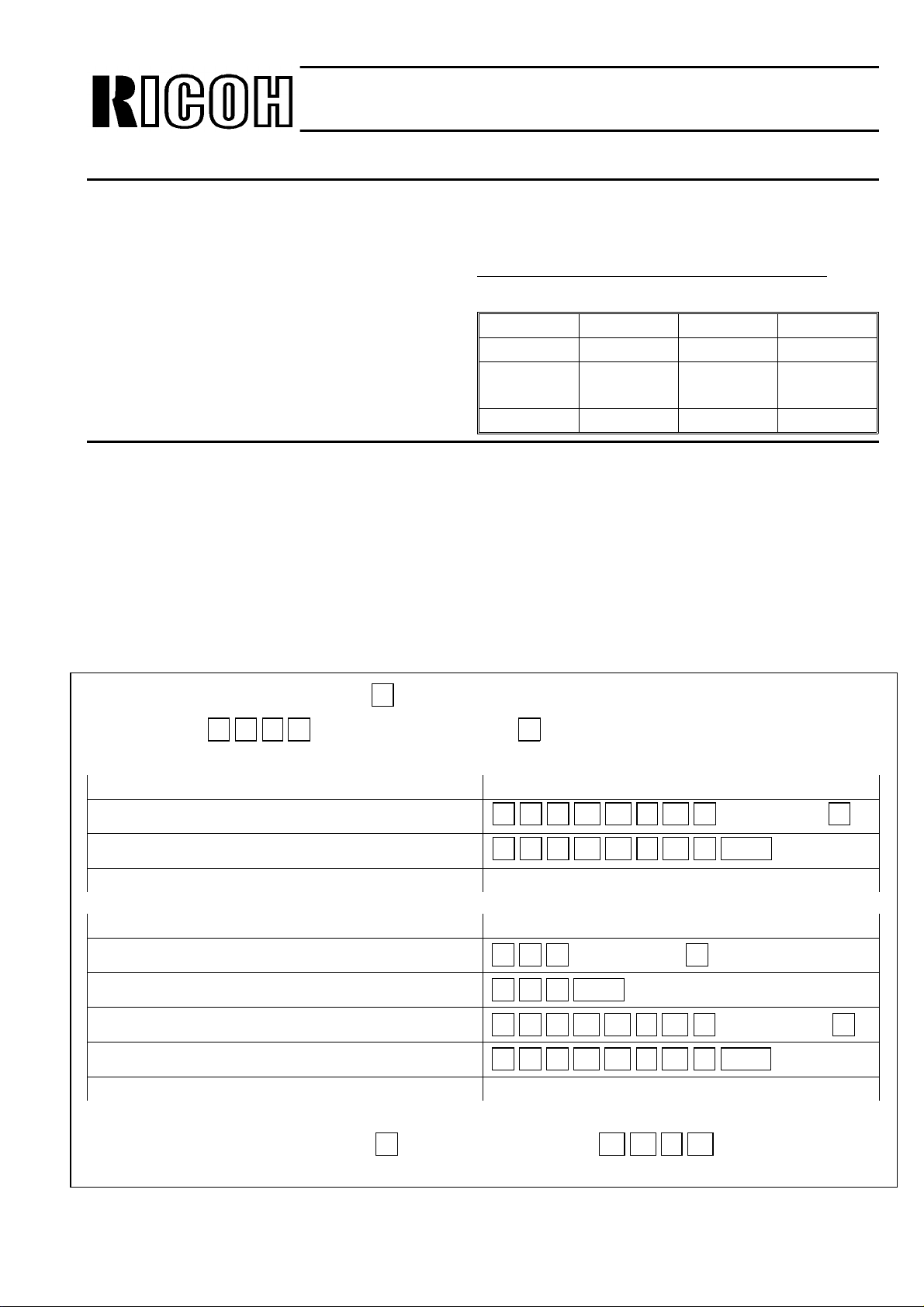
Control No. for Ea ch Area
R.C. 03 Europe 02
SAVIN -- HCS 02
NRG-
USA
-- NRG 02
Asia/LAM 02
If you are receiving some calls from custo mers ab out this, please give them the correct inf orma tion.
These feature s are available in the A F2 models only.
Dial your machine. → Press
→ Press
- Current -
Remote Tra nsf er o f a Po lling File
Remote Printing of a polling File
- Correct-
Remote Tra nsf er of a Fre e Polling File
Remote Printing of a Free Polling File
Remote Tra nsf er of a Secured Polling File
a b c d (Remote ID), then press # . After that, do the following.
# when you hear a high-pitched tone.
2 0 # i j k l # Fax Number #
2 1 # i j k l # Start
2 0 # Fax Number #
2 1 # Start
2 2 # i j k l # Fax Number #
Remote Printing of a Secured Po lling File
To disconnect the line, press # twice. i j k i : ID Code (Polling)
We will try to revise the manuals from the next printing run.
2 3 # i j k l # Start

Issued on
March 18th, 1992
Technical Bulletin
No. CSO-008
Subject:
Model(s): AFO/AF2/CSO
Classification
-Problem-
If the T1 timer is set with a value of over 100 for a speed dial code by d ed icated Tx parameter
programming, the other parame te r for th e spe ed dial cod es will not be programmed.
Dedicated Tx parameter programming problem
FA X T.S. Section, T.S. Department
Assistant General Manager
H. Motojima
Control No. f or Each Area
R.C. 004 Europe 007
SAVIN 004 HCS 007
NRG-
USA
001 NRG 001
Asia/LAM 005
-Cause-
Software bug.
-Countermeasure-
Temporary- Set the T1 timer with a value less than 100 for spe ed dia l codes.
Permanent - We will correct the software from the May mass pro duction.

Page
418E=12H
1
Technical Bulletin
KMxml
Subject:
Model(s): AFO/AF2
Classification
Action Required
u-
Troubleshooting
❑
Retrofit Information
❑
Revision of Service Manual
Information Only
El
❑
Others
When installing the above models in Sweden, change the
PTT/sales
the
NCU
Cso
requirements as follows.
No.cso-009
parameter setting
for
FAX
Assistant General Manager
H.
Control No. for Each Area
Sweden
T.S.
Section
McWinTJii-nTJ>z~
R.C. --
SAVIN
NRG-USA
Issued on
March 19th, 1992
T.S.
Department
j
,
)
(Y
Europe
--
--
NCU
parameter in accordance with
HCS
NRG
Asia/LAM
008
008
002
--
1. Change the country codes for NCU parameter and bitswitches.
2. Change the and RAM addresses and bit switch as follows.
(PTT requirement)
Address 4172 = 60H
Address 4173 = 20H
Address 4174 = 60H
Address 4175 = 03H
Address 4176 = 19H
The above correction will be applied into the software from the
(Sales requirement)
Address 406C bit 5 =
Address 4063 bit 7 = O
Bit sw SW06 = F0H
1st
bit6=l
0,
productions of May ’92.
4143=28H
4145=28H
4151=28H
4153=28H
4172=28H
4174=28H
Page 1
Technical Bulletin
No.AFO-004
Subject:
Issued on
April 23rd, 1992
Modification of cutter unit
Model(s): AFO/AF2
FAX T.S. Section, T.S. Department
Assistant General Manager
Classification
H. Motojima
From the July, 1991 production, to prevent from paper jam at the cutt er exit, a mylar has been
attached to the cutter blade (Diagram A).
The affe cte d models and cutters are shown below.
No. Cutter Unit Part No.
1 Cutter - A4 for model C (Hitachi) H0532161H
2 Cutter - A4 f or model C (Ooyane) H0532150G
3 Cutter - B4 for FAX 82 H0542156C
4 Cutter - A4 f or AFO H0845028C
With this modification, the guide plate of the cutt er exit was discontinued afte r the old cut ter
assembly was out of stock (Diagram B).
This discontinuance has been applied from the February, 1992 production.
However, we found in the production line that few ma chin es experienced paper jam due to th e
discontinuance of th e gu ide plate.
[Cause]
The cause of this paper jam is as follows.
In some machines there might be a clearance between the guid e plate for paper feed-out and
the mylar (Diagram C).
Therefore, the printed page gets into the clearan ce an d then a paper jam occurs.
The number of cases of paper jam in the prod uction line were 5/2035(0.2%).
[Countermeasure]
We have applied the following countermeasures in order to ensure the paper feeds correctly.
Page 2
Technical Bulletin
No.AFO-004
Issued on
April 23rd, 1992
Subject:
Modification of cutter unit
-Temporary-
Two (four) spacers were attached between the feed-out roller holder and the feed-out guide
plate, to get rid of the clearance (Diagram D).
This was done in the March production .
-Permanent-
The guide plate of the cu tt er exit has been reattache d.
This was done all the way from the A pril pro du ctio n.
No. Old P/# of cutter T em porary Action Perm ane nt Action New P/# of cutter
1 H0532161H
2 H0532150G
3 H0542156C
4 H0845028C
To be attached 0.9mm
spacer
(P/# H0542153)
To be attached 0.9mm
spacer
(P/# H0542153)
Not
countermeasure
To be attached
0.9 +0.5mm spacer
•0.9mm spacer
(P/#:
… H0542153
•0.5mm spacer
… 07080030B)
To be attached the guide
plate of the cutter exit
(no part number)
To be attached the guide
plate of the cutter exit
(no part number)
To be attached the guide
plate of the cutter exit
(no part number)
To be attached the guide
plate of the cutter exit and
0.9mm spacer
•Guide plate
(P/#:
… no part number
•0.9mm spacer
… H0542153)
H0532161J
H0532150H
H0542156D
H0845028D
If you need the above parts for countermeasure, please deal with the following way.
0.9mm and 0.5mm spacer … Please order from SPC
Guide plate of th e cutter exit … Please contact our section attent ion to Mr. H.Motojima.
[Affected models in the field]
The machines which have not ha d an y coun termeasures applied before bein g shipped out are
as follows.
• From Tokyo
→ To Asia … Less than 1230 units
→ To USA … Less than 805 units
• From RIF (France)
→ To Europe … A few units
Page 3
Technical Bulletin
No.AFO-004
Subject:
Issued on
April 23rd, 1992
Modification of cutter unit
[Solution]
The design section tested the machine und er a bn orma l conditions (They teste d 4 un its o f A FO
after adjusting the clearance to the widest.)
The result of testing is shown be low.
No. Clearance (mm) Occurrence Rate
1 -2.0 0/3685
2 -1.75 0/3786
3 -1.8 0/3759
4 -1.65 0/3685
We guess that paper jams caused by this tolerance problem wo uld occur rare ly, according to
the test result.
Also, the frequency should almost be with in th e spe cification (less than 1/1000).
However, if paper jam occurs in the field, and if the guide plate of the cutter exit is not used in
the cutter, you should attach the guide plate to the cutter or attach the spacers between the
feed-out roller holder and the feed-out guide plate.
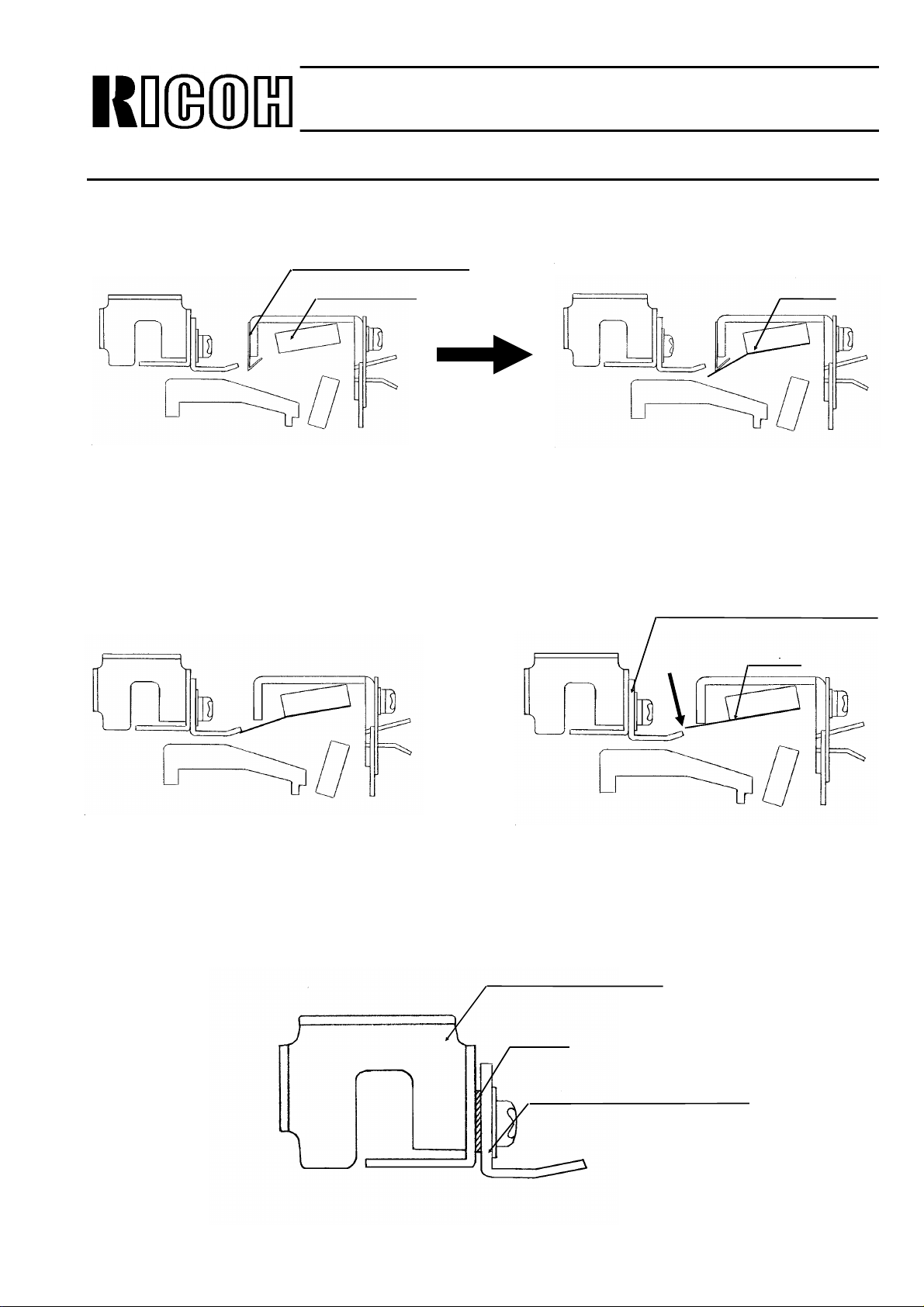
Mylar
[Diagram C]
Clearance
Page 4
Subject:
Technical Bulletin
No.AFO-004
Modification of cutter unit
Guide Plate - Cutter Exit
Cutter Blade
[Diagram A]
Issued on
April 23rd, 1992
[Diagram B]
Guide Plate - Paper Feed-out
Mylar
Feed out Roller Holder
Spacer
Guide Plate - Paper
[Diagram D]

Issued on
April 24th, 1992
Technical Bulletin
No.CSO-011
Subject:
Model(s): AFO AF2/CSO
Classification
Action Required
Troubleshooting
Retrof it Information
Revision of Service Manual
Inform a tion Only
Others
When installing the above models in Switzerland, you have to apply th e modification as the
following steps.
NCU Modifi cation for Switzerland
(Europe only)
FAX T. S. Section, T.S. Depa rtmen t
Assistant General M anager
H. Motojima
1. Prepare the following parts at your side.
(1) Resister - 10Ω: 1/10W
(2) Capacitor - 0.047µF /250V
(3) C oil - TDK ELF 1010 SKI-332k (3.3mH)
2. Remove the NCU from the machine, then apply the modification.
(1) Replace the R17 with the above resister (10Ω)
(2) Add the capacitor and coil, and cut the pattern as shown on the next page.
3. Put the NCU back, and reassemble the machine.
4. Check the machine for the following items.
• Dialling (PD/DTMF)
• Transmission
• Reception

Issued on
May 12th, 1992
Technical Bulletin
No.CSO - 013
Subject:
Model(s): AFO / AF2 / CSO
Classification
[Problem]
The above models may not transmit to the following models.
(Error code 0 - 21 / 0 - 23)
The document may stop during scanning, then the mach ine will reset after 1 ∼ 2 min, and the
power failure report will be printed.
During transmission, th e stop key does not function.
Condition : I / O rate 40ms (standard), 20ms (Detail)
Models : UF32H • UF23 (Matsushita)
Communication Problem
FA X T.S. Section, T.S. Department
Assistant General Manager
H. Motojima
[Cause]
A sof tware error
On the Tx side, the fill bit will be added if the 1 line data is less than the min Tx time for 1 line,
however on the above AFO / AF2 / CSO, the counting may be incorrect.
[Countermeature]
Temporary : Using the dedicated Tx parameter, select 4800bps of the initial modem rate.
Permanent : The 1st production of March ’92 will con ta in t he correct software.

Issued on
May 12th, 1992
Technical Bulletin
No. CSO - 014
Subject:
Model(s): AFO / AF2 / CSO
Classification
[Problem]
The avove models can not re ceive using ECM from the machines which use 64 fra mes, such as
Canofax 470.
Communication Problem
FA X T.S. Section, T.S. Department
Assistant General Manager
H. Motojima
[Cause]
A sof tware error
The frame size (256 / 64 frame) can no t be chan ge d in the software.
[Countermeature]
Temporary
If you face this problem, switch off the ECM function.
(Bit sw 07, bit 5 0 → 1)
In the field, most of facsimile machines use 256 frame, so, this problem may occur rarely.
Permanent
The 1st production of May ’92 will con ta in the corre ct software.

Issued on
May 22nd, 1992
Technical Bulletin
No. CSO - 017
Subject:
Model(s): AFO / AF2 / CSO (Europe)
Classification
[Problem]
When installing the above mode ls in De nma rk, S witzerland and Austria, change the follo wing
addresses in accordance with the PTT requierments it the machine Serial Number is prior to the
following excution date.
1. Change the country codes for NCU parameter and bit switch.
2. Change the RAM addresses as follows.
NCU parameter setting for Denma rk, Switz erland and Aus tr ia
FA X T.S. Section, T.S. Department
Assistant General Manager
H. Motojima
[Denmark]
4149 =04H, 414A =60H, 414B =03H, 414C =90H, 415B =OCH, 415C =OCH,
415D =08H, 415E =17H, 414D =05H, 41 4E =1 2H, 414F =0 3H, 4150 =40 H,
4151 = 41H, 4152 = 3FH, 4153 = 41H, 4154 = 04H, 4155 = 19H, 4157 = 04H,
4158 =60H, 4159 =03H, 415A =90H, 4164 =42H
These corrections have bee n applie d fro m t he 1st pro du ctio n of March ’92 .
[Switzerland]
4181 =05H, 4143 =28H, 4145 =28H, 41 64 =51H, 415B =18, 415C =1EH,
415D =OFH, 415E =16H, 415F =OBH, 4160 =OBH, 4161 =08H, 4162 =1EH,
4064(bit 5) =1
These corrections have bee n applie d fro m t he 1st pro du ctio n of May ’92.

Subject:
Issued on
May 22nd, 1992
NCU parameter setting for Denma rk, Switz erland and Aus tr ia
[Austria]
AFO/AF2/CSO
Addr.
4058: → 0AH
4059: → 01H
4143: → 28H
4178: → 64H
417D: → 0EH
417E: → 0AH
417F: → 01H
4182: → 14H
4183: → 50H
4187: → 09H
4190: → 50H
4191: → 50H
4192: → 07H
Technical Bulletin
No. CSO - 017
CSO
Bit SW
Bit SW 01: → 03H
Bit SW 02: → 40H
Bit SW 03: → 4AH
Bit SW 05: → 27H
Bit SW 07: → 46H
Bit SW 0B: → 06H
Depending on the sales req uire ment, change
the followings.
User SW
User Bit SW 01: → 41H
User Bit SW 02: → 0BH
User Bit SW 03: → F5H
User Bit SW 06: → 0BH
AFO/AF2
Bit SW
Bit SW 01: → 07H
Bit SW 02: → 58H
Bit SW 03: → 4AH
Bit SW 05: → 27H
Bit SW 07: → 06H
Bit SW 0B: → 06H
Depending on the sales req uire ment, change
the followings.
User SW
User SW 03: → F5H
After correcting the sof tware, we will apply to the machine(excep t use r SW ).
Technical Bulletin No. CSO-022
Page 1/3
SUBJECT: Modem Capture Range Problem
PREPARED BY: N.Mihara
CHECKED BY:
CLASSIFICATION:
Action Required Revision of service manual
Troubleshooting Information only
Retrofit Information Other
FROM: FAX T.S. Section
MODEL: CSO, AFO, AF2
DATE: August 21st, 1992
Reissued: Sept 29, 1992
[Problem]
The CSO/AFO/AF2 may not receive at 9600bp s/7200bps from the certain machines, with the
following phenomenon.
• Error code: 0-21, 23
• Only the 1st few inches (cm) of the image da ta would be received and then the line wou ld
be disconnected, or the error would occur as the usual Line fail.
[Cause]
On the CCITT recommendation, the signalling r a te o f the TX terminal is defined to be 9600bps
± 0.01% (100ppm), and all makers design the facsimile models in accordance with the CCITT
recommendation. However, on the some of the models (Tx side) , the signallin g rate may be out of
CCITT recommendation, due to the possible production variation of modem, or other factors.
The capture range (Rx capability) of t he CSO/AFO/AF2 is designed as 9600bps ± 100ppm(there is
no margin). Therefor e, if the signalling rate of Tx terminal is out of CCITT recom mendation, the
CSO/AFO/AF2 can not receive the V29 signal correctly. It means that, if a modem is produced
precisely, there will not be the problem.
Tx side: Signalling rate of CCITT recommendation - 9600bps ± 100ppm
Rx side: Capture range of CCITT recommendation - none
[Countermeasure]
Permanent: We have re-designed the modem, to have cert ain margin fo r reception and the new
modem will be ap plied from Oct. produ ctions of ’92 except the fo llowing.
CSO (Productions at RIF factory) → From November, 1992
AFO/AF2 (Productions at RIF factory) → Fro m December, 1992.
The P/Ns of the FCUs will be changed as follows.
Old New
H08160xx → H08161xx (The last two digits will not be changed)
H08460xx → H084603x
H08660xx → H086603x
(The last digit will not be changed)
Technical Bulletin No. CSO-022
Page 2/3
SUBJECT: Modem Capture Range Problem
DATE: August 21st, 1992
Reissued: Sept 29, 1992
[Action in the field]
(1) Make sure the exact causes of the communication problem. By referring to the attached
troubleshooting flow, because there are other communication problems which are caused by
other reasons. If the problem is caused by this modem capture range problem, go to the next
steps.
(2) Drop the starting modem rate of the terminal for Rx or Tx.
(3) Ask the Tx terminal to replace the modem.
(4) If (3) is not po ssible, replace the FCU with the new FCU which contains the new modem.
[Sample]
Until now, we have been reported on this problem with the following models at few rate, and as
the result of our investigation, the signalling rates of the machines are as follows.
Models Signalling rate
SANFAX 2100 Unknown (The modem has been
rep laced on the tx side)
SANFAX 1 -163pp m
SANFAX 515 Unkno wn
Panafax UF1000 -120ppm
PC98 FAX (Star FA X) + 120ppm
PC FAX Mac -180ppm
IBM PC FAX Unknown
Please note that the above table is just the samples of the problem, and the problem should not
always occur with the above models in your field.
The estimated occurrence rate is as low as 0.05%/mo.
However, we like to keep watching the field performance.
We like you to log this case monthly.
 Loading...