

Ricoh FAX500 Service Manual FX550 [E]

FAX550
SERVICE M ANUAL
Throug hout this manual, the machines are
referred to as follows.
Type A: FAX500
Type B: FAX550

Lithium Batteries (Memory Back-up)
CAUTION:
The danger of explosion exists if a battery of this type is incorrectly rep laced.
Replace only with the same or an equivalent type recommended by the
manufacturer. Discard used batteries in accordance with the manufacturer’s
instructions.

CONTENTS
1. OVERALL MACHINE INFORMATION
1.1. SPECIFICATIONS . . . . . . . . . . . . . . . . . . 1-1
1.2. FEATURES . . . . . . . . . . . . . . . . . . . . . 1-2
1.3. COMPONENT LAYOUT . . . . . . . . . . . . . . . . 1-5
1.3.1. Mechanical Components . . . . . . . . . . . . . . 1-5
1.3.2. Drive Components . . . . . . . . . . . . . . . . . 1-6
1.3.3. Electrical Compon ents . . . . . . . . . . . . . . . 1-7
1.4. OVERALL SYSTEM CONTROL . . . . . . . . . . . . . 1-9
1.5. VIDEO DATA PATH . . . . . . . . . . . . . . . . . . 1-10
1.5.1. Transmission . . . . . . . . . . . . . . . . . . . 1-10
1.5.2. Reception . . . . . . . . . . . . . . . . . . . . 1-10
1.6. POWER DISTRIBUTION . . . . . . . . . . . . . . . . 1-11
1.6.1. Distribution Diagram . . . . . . . . . . . . . . . . 1-11
1.6.2. Memory Back-up Circuit . . . . . . . . . . . . . . . 1-12
2. DETAILED SECTION DESCRIPTIONS
2.1. SCANNER . . . . . . . . . . . . . . . . . . . . . . 2-1
2.1.1. Mechanisms . . . . . . . . . . . . . . . . . . . 2-1
1. Document Detection . . . . . . . . . . . . . . . . . 2-1
2. Pick-up and Feed . . . . . . . . . . . . . . . . . . 2-2
2.1.2. Video Data Processing . . . . . . . . . . . . . . . 2-3
2.2. PRINTER . . . . . . . . . . . . . . . . . . . . . . 2-4
2.2.1. Mechanisms . . . . . . . . . . . . . . . . . . . 2-4
1. Paper Feed . . . . . . . . . . . . . . . . . . . . 2-4
2. Cutting . . . . . . . . . . . . . . . . . . . . . . 2-5
3. Cutter Jam Detection . . . . . . . . . . . . . . . . 2-5
2.2.2. Circuits . . . . . . . . . . . . . . . . . . . . . 2-6
1. Video Data Processing . . . . . . . . . . . . . . . . 2-6
2. Thermal Head . . . . . . . . . . . . . . . . . . . 2-6

2.3. PCBs AND THEIR FUNCTIONS . . . . . . . . . . . . . 2-7
2.3.1. FCU . . . . . . . . . . . . . . . . . . . . . . 2-7
2.3.2. MBU . . . . . . . . . . . . . . . . . . . . . . 2-9
2.3.3. SBU . . . . . . . . . . . . . . . . . . . . . . 2-10
2.3.4. OPU . . . . . . . . . . . . . . . . . . . . . . 2-10
2.3.5. NCU . . . . . . . . . . . . . . . . . . . . . . 2-11
1. PCB Block Diagram . . . . . . . . . . . . . . . . . 2-11
2. Signal and Jumper Settings . . . . . . . . . . . . . . 2-12
2.3.6. PSU . . . . . . . . . . . . . . . . . . . . . . 2-13
3. INSTALLATION
3.1. CONNECTING UP THE MACHINE . . . . . . . . . . . . 3-1
3.2. INITIAL PROGRAMMING . . . . . . . . . . . . . . . 3-2
3.3. LANGUAGE ROM SELECTION . . . . . . . . . . . . . 3-2
4. SERVICE TABLES AND PROCEDURES
4.1. SERVICE LEVEL FUNCTIONS . . . . . . . . . . . . . 4-1
4.1.1. Bit Switch Programming (Function 91) . . . . . . . . . 4-1
4.1.2. System Parameter List (Function 92) . . . . . . . . . . 4-1
4.1.3. Error Code Display (Function 93) . . . . . . . . . . . 4-2
4.1.4. Service Monitor (Function 93) . . . . . . . . . . . . . 4-2
4.1.5. Protocol Dump (Function 94) . . . . . . . . . . . . . 4-2
4.1.6. RAM Display/Rewrite (Function 95) . . . . . . . . . . 4-3
4.1.7. RAM Dump (Function 95) . . . . . . . . . . . . . . 4-3
4.1.8. NCU Parameters (Function 96) . . . . . . . . . . . . 4-4
4.1.9. ADF Test (Functio n 97) . . . . . . . . . . . . . . . 4-4
4.1.10. Xenon Lamp Test (Function 97) . . . . . . . . . . . 4-5
4.1.11. DTMF Tone Test (Function 97) . . . . . . . . . . . . 4-5
4.1.12. Printer Test Patterns (Function 97) . . . . . . . . . . 4-6
4.1.13. Operation Panel Test (Function 97) . . . . . . . . . . 4-6
4.1.14. Modem Test (Function 97) . . . . . . . . . . . . . 4-7
4.1.15. Ringer Test (Function 97) . . . . . . . . . . . . . . 4-8
4.1.16. Buzzer Test (Function 97) . . . . . . . . . . . . . . 4-8
4.1.17. Sensor Initialization (Function 97) . . . . . . . . . . . 4-8
4.1.18. Serial Number (Function 98) . . . . . . . . . . . . . 4-9
4.1.19. Pulse Width (Function 99) . . . . . . . . . . . . . . 4-9
4.1.20. Bypassing Restricted Access . . . . . . . . . . . . 4-10
4.1.21. Printing all Memory Files . . . . . . . . . . . . . . 4-10

4.1.22. CSI Programming . . . . . . . . . . . . . . . . . 4-11
4.1.23. Telephone Line Type Selection . . . . . . . . . . . . 4-11
4.2. BIT SWITCHES . . . . . . . . . . . . . . . . . . . . 4-12
4.3. NCU PARAMETERS . . . . . . . . . . . . . . . . . . 4-24
4.4. DEDICATED TRANSMI SSION PARAMETERS . . . . . . . 4-39
4.4.1. Programming Procedure . . . . . . . . . . . . . . 4-39
4.4.2. Parameters . . . . . . . . . . . . . . . . . . . . 4-40
4.5. USEFUL RAM ADDRESSES . . . . . . . . . . . . . . 4-42
4.6. SPECIAL TOOLS AND LUBRICANTS . . . . . . . . . . . 4-44
5. REPLACEMENT AND ADJUSTMENT
5.1. COVERS . . . . . . . . . . . . . . . . . . . . . . 5-1
5.1.1. Top Co ver . . . . . . . . . . . . . . . . . . . . 5-1
5.1.2. Front and Rear Covers . . . . . . . . . . . . . . . 5-1
5.2. SCANNER . . . . . . . . . . . . . . . . . . . . . . 5-2
5.2.1. ADF Clutch and Pick-up and Feed Rollers . . . . . . . . 5-2
5.2.2. Separation Roller . . . . . . . . . . . . . . . . . 5-3
5.2.3. Tx Motor . . . . . . . . . . . . . . . . . . . . . 5-4
5.2.4. Timing Belt Tension Adjustments . . . . . . . . . . . 5-4
5.2.5. Xenon Lamp . . . . . . . . . . . . . . . . . . . 5-5
5.2.6. Xenon Lamp Driver . . . . . . . . . . . . . . . . . 5-5
5.2.7. SBU . . . . . . . . . . . . . . . . . . . . . . 5-6
5.2.8. SBU Adjustments . . . . . . . . . . . . . . . . . 5-6
5.3. PRINTER . . . . . . . . . . . . . . . . . . . . . . 5-10
5.3.1. Rx Motor . . . . . . . . . . . . . . . . . . . . 5-10
5.3.2. Thermal Head . . . . . . . . . . . . . . . . . . 5-10
5.3.3. Cutter . . . . . . . . . . . . . . . . . . . . . . 5-11
5.4. PCBs . . . . . . . . . . . . . . . . . . . . . . . . 5-12
5.4.1. FCU and Battery . . . . . . . . . . . . . . . . . . 5-12
5.4.2. Memory . . . . . . . . . . . . . . . . . . . . . 5-12
5.4.3. MBU . . . . . . . . . . . . . . . . . . . . . . 5-13
5.4.4. PSU and NCU . . . . . . . . . . . . . . . . . . . 5-14
5.4.5. Operation Panel . . . . . . . . . . . . . . . . . . 5-14

6. TROUBLESHOOTING
6.1. COPY QUALITY TROUBLESHOOTING . . . . . . . . . . 6-1
6.1.1. Received Copies . . . . . . . . . . . . . . . . . . 6-1
6.1.2. Copies made in Copy Mode . . . . . . . . . . . . . 6-1
6.2. MECHANICAL PROBLEMS . . . . . . . . . . . . . . . 6-2
6.2.1. ADF/Scanner . . . . . . . . . . . . . . . . . . . 6-2
6.2.2. Printer . . . . . . . . . . . . . . . . . . . . . . 6-5
6.3. ERROR CODES . . . . . . . . . . . . . . . . . . . 6-7
6.4. DEFECTIVE SENSOR TABLE . . . . . . . . . . . . . . 6-1 3

OVERALL MACHINE INFORMATION November 30th, 1991
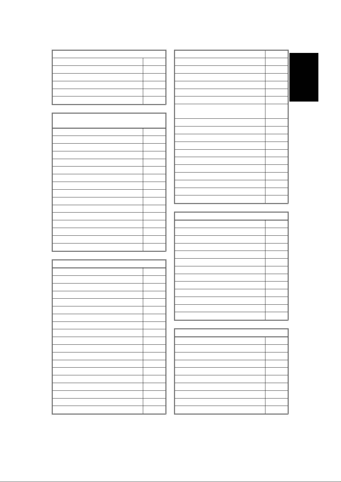
SPECIFICATIONS
1. OVER ALL MACHINE INFORMATIO N
1.1. SPECIFICATIONS
Type
Desktop transceiver
Protocol
Group 3 with ECM
1
Circuit
PSTN, PABX
Connection
Direct couple
Document Size
Length: 105 - 1200 mm
[4.13 - 47.2 ins]
Up to 100 m [328 ft] after adjustment
Width: 148 - 216 mm
[5.8 - 8.5 ins]
Thickness: 0.05 to 0.15 mm
[2 to 6 mils]
Document Feed
Automatic feed, face down
ADF Capacity
30 sheets (using 80 g/m
Scanning Method
Flat bed, with CCD
Maximum Scan Width
216 mm [8.5 ins] ± 1%
Scan Resolution
Main scan: 8 dots/mm [203 dpi]
Sub scan:
Standard - 3.85 lines/mm [98 lpi]
Detail - 7.7 lines /mm [196 lpi]
Fine - 15.4 lines/mm [392 lpi]
Memory Capacity
ECM: 128 kbytes (double buffer)
SAF: 256 kbytes (14 pages), with
optional extra 1 Mbyte or
2 Mbytes (max 71 or 128
pages respectively)
Compression
MH, MR, E FC, MMR , SSC
Storage to SAF memory for tx: MH
MMR only with EC M
2
paper)
Data Rate
9600/7200/4800/2400 bps; automatic fallback
I/O Rate
With ECM : 0 ms/line
Without ECM: 5, 1 0, 20, or 40 ms/line
Transmi ssi o n Time
10 s at 9600 bps (G3 ECM using memory)
for a CCITT #1 test document (Slerexe letter) using standard resolution
Printing System
Thermal printing, automatic cutter
Pap er Size
216 mm (A4) x 100 m [8.5 ins x 328 ft]
Maximum Printout Width
210 mm [8.3 ins]
Ma ximu m Printer Resoluti o n
Main scan: 8 dots per mm [203 dpi]
Sub scan: 15. 4 lines/mm [392 lpi]
Power Supply
220 - 240 Vac, 50 Hz
Power Consumption (Base Machine Only)
Standby: 13 ± 5 W
Transmit: 29 ± 5 W
Receive: 22 ± 5 W
Copying: 41 ± 7 W
Operating Environment
Temperature: 17 - 28 °C [63 - 82 °F]
Humidity: 30 - 85 %Rh
Dimensions (W x D x H)
325 x 388 x 174 mm [12.8 x 15.3 x 6.9 ins]
Excluding handset, trays, and optional units
Weight
10 kg [22 lbs]
Modulation
V.29 (QAM), V.27ter (PHM), V.21 (FM)
1-1

November 30th, 1991 OVERALL MACHINE INFORMATION
FEATURES
1.2. FEATURES
KEY:
O = Used, X = Not Used,
A = With optional memory only,
G = Not used in Germany,
S = Service mode in some countries
Equipment
ADF O
Bar code reade r X
Built-in handset X
Cabinet X
Connection for ans. machine X
Connection for handset O
Cutter O
Handset O
Hard disk X
Magnetic card reader X
Manual f eed mechanism X
Marker X
Microphone X
Monitor speaker O
R emaining memory indicator O
Speakerphone X
Video Processing Features
Contrast O
Halftone (B asic & Error Dif fusion) O
MTF O
Reduction O
R e s olution O
Smoothing - 8 x 3.85 to 8 x 7 . 7 O
Smoothing - 8 x 7.7 to 8 x 15 . 4 X
Communication Features - Auto
Automatic fallback O
Automatic redialling O
Confidential reception A
Dual Acce ss O
Substitute r ecepti on O
Transmission Reserve O
Communication Features -
User Selectable
Action as a transfer broadcaster X
AI Redial O
Alternative Destination O
Answering machine X
Authorize d Reception O
Auto-answer dela y time X
Auto dialling (pulse or DTMF ) O
Auto Documen t O
Automatic Voice Message X
Auto-note X
Batch Transmission (max 5 files) A
Broadcasting O
Chain Dialling O
Confidential ID O v erride O
Confidential Transmission O
Forwarding (4 stations) A
Fre e Polling O
Gr oups (7 groups) O
Hold O (G)
Immediate Redialling O
Immediate transmission O
Keystr oke Program s O
Mailbox C
Memory transmission O
Notify X
On Hook Dial O (G )
Page Count O
Per sonal Codes O
Personal Codes with Conf ID A
Polling R eception O
Polling Transmission O
Quick Dial (3 0)
Reception mode s (Fax, Te l, Auto) O
Reduction X
Remote control features O
Remote Transfer O
Restricted Access (10 codes,
without cards)
Secured Polling O
Secured Polling with Stored ID
Override
Send Later O
Silent ringing detection X
O
O
1-2
OVERALL MACHINE INFORMATION November 30th, 1991
FEATURES
Speed Dial (100)
Telephone Directory O
Tonal Signal Transmission O
Transfer Request: 30 stations O
Transmission Deadline X
Turnaround Polling X
Voice Request O
Communication Features -
Service Selectable
AI Short Protocol X
Auto-reduction override option X
Bus y tone detection O
Close d network (tx and rx) O
Continuous Polling Re ception O
Dedicate d t x paramete r s O
ECM O
EFC O
MV1200 compatibility X
Page retransmission O
Page separation m ark X
Polling tx file lifetime in the SAF O
Protection against wrong conn. O
R esol’n stepdown override option X
Short Preamble O
W ell log O
Other User Features
Auto Service Call X
Ce n ter mark X
Chequere d mark X
Clea ring a memory file O
Clea ring a polling file O
Clock O
Confidential ID A
Copy m ode O
Counters O
Di alled n umber che ck X
Direct entry of names O
Function Progr ams O
ID Code O
Label Insertion O
Language Selection O
LCD contrast control Se r vice
Memory L ock A
Memory L ock ID A
Modifying a memory file X
Mu lti So rt Document Rece p t ion X
Multicopy m ode X
Night Timer X
Own t elephone number O
Printing a memory file O
RDS on/off O
R eception Mode Switching Ti mer O
Reception Time (non- memory rx
only)
Re mote ID O
R everse Order Printing X
RTI, TTI, CSI O (S)
Speaker volume control O
Specified Cassette S election X
Substitute r ecepti on on /of f O
Telephone line type O (S)
TTI on/off O
Use r Function Keys X
User Parameters O
Wild Cards O
Reports - Automatic
Charge Control Report X
Communication Failure Report O
Confidential File Report A
Error Report O
Memory Storage Report O
Mode Chan ge Report X
Polling Clea r Report O
Polling R eserve Report O
Polling R esult Report O
Power Failure Report O
Journal O
Transfer Result Report X
Transmission Result Report O
Reports - User-initiated
Authorized Reception List O
Charge Control Report X
File L is t O
Forwarding List O
Gr oup List O
Per sonal Code List O
Program List O
Quick Dial List O
Specified Cassette Selection List X
Speed Dial List O
O
1
1-3

November 30th, 1991 OVERALL MACHINE INFORMATION
FEATURES
Reports - User-initiated
Journal O
Transmission Status Report X
User Function List X
Use r Paramete r List O
Service Mode Features
Back-to-back t est O
Bit switch programming O
Buzzer test O
Cable equaliz er (rx only) O
Comm. par ameter display O
DTMF tone test O
Echo countermeasure O
Error code display O
LCD contrast control O
Memory file forwarding O
Memory file printout (all files) O
Modem te st O
NCU parameters O
Operation panel test O
Printer mechanism test X
Printer te st patterns O
Progra mmable atten u ation X
Protocol dum p list O
R AM display/rewrite O
RAM dump O
R inger tes t X
Scanner la mp test O
Scan n er mechanism test O
Sens or initialization O
Serial number programming O
Service m onitor repor t O
Serv ice s tation number X
Syste m parameter list O
Technical data on the Journal O
T h ermal head parameters O
Transmission Status Report X
Memory Files
Max. number of files: 100
Max. number of stations/file: 142
Max. number of stations overall: 299
Max. number of pages overall: 200
(including pages stored as Auto
Documents)
1-4
OVERALL MACHINE INFORMATION November 30th, 1991
COM PONEN T LAYOUT
1.3. COMPONENT LAY O UT
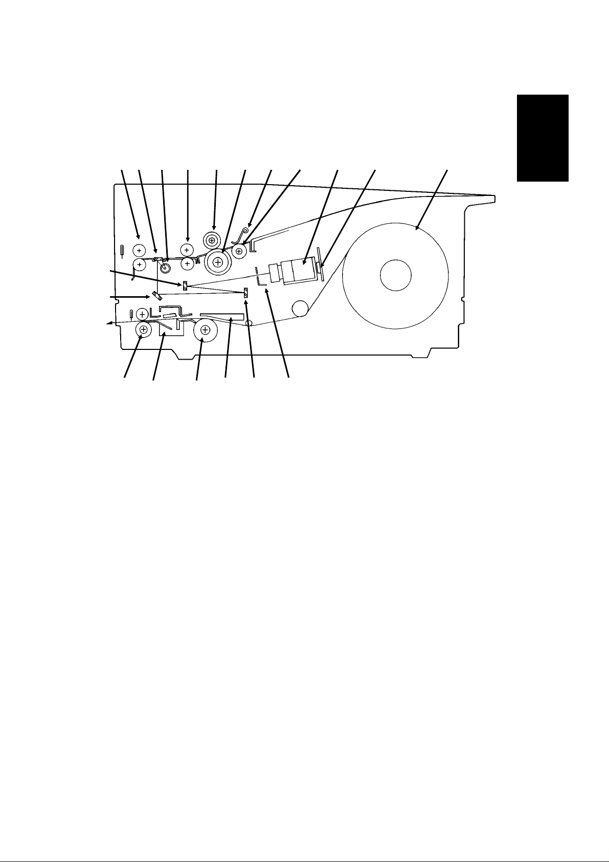
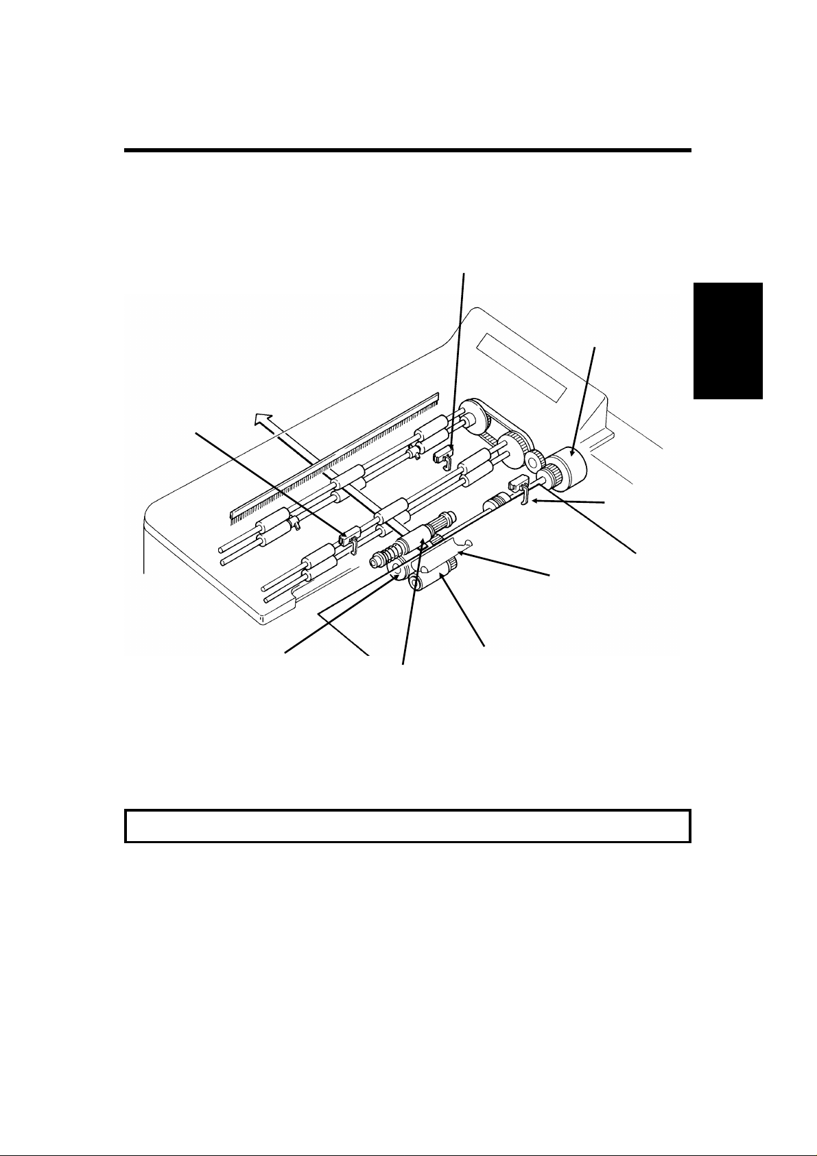
1.3.1. Mechanical Components
123456 78 9 10 11
19
18
1
121317 16 15 14
1. R2 Rollers Feed the document through the scanner.
2. Exposure Glass E xposes the original to light from the xenon lamp.
3. Xenon Lamp Illuminates the document.
4. R1 Rollers Feed the document through the scanner.
5. Separation Roller Allows one page into the scanner .
6. Document Feed Roller Feeds the document into the scanner.
7. Separation P lat e Spreads out the leading edges of the pages fed into the
scanner.
8. Pick-up Roller Picks up pages of the document from t he document
table .
9. Lens Block Focuses light reflected from the document onto the
CCD.
10. CCD (Charge Coupled
Device)
11. Thermal Paper Roll Thermal paper for printing.
12. Shading Plate Allows more light through from the ends of the xenon
13. Second Mirror Ref l ects light from the document towards the CCD.
14. Thermal Head P rints received data on the therma l paper.
15. Platen Roller Feeds the pa per through the printer.
16. Cutter Cuts off the printed page.
17. Feed-out R ollers Feed out the page which has been cut off.
18. First Mirror Refle cts light from the document towards the CCD.
19. Third Mirror Refle cts light from the document towards the CC D.
This converts the light reflected from the document into
an analog video signal.
lamp than from the centre, to counteract the relative
dimness at the ends of the lamp.
1-5
November 30th, 1991 OVERALL MACHINE INFORMATION
COM PONEN T LAYOUT
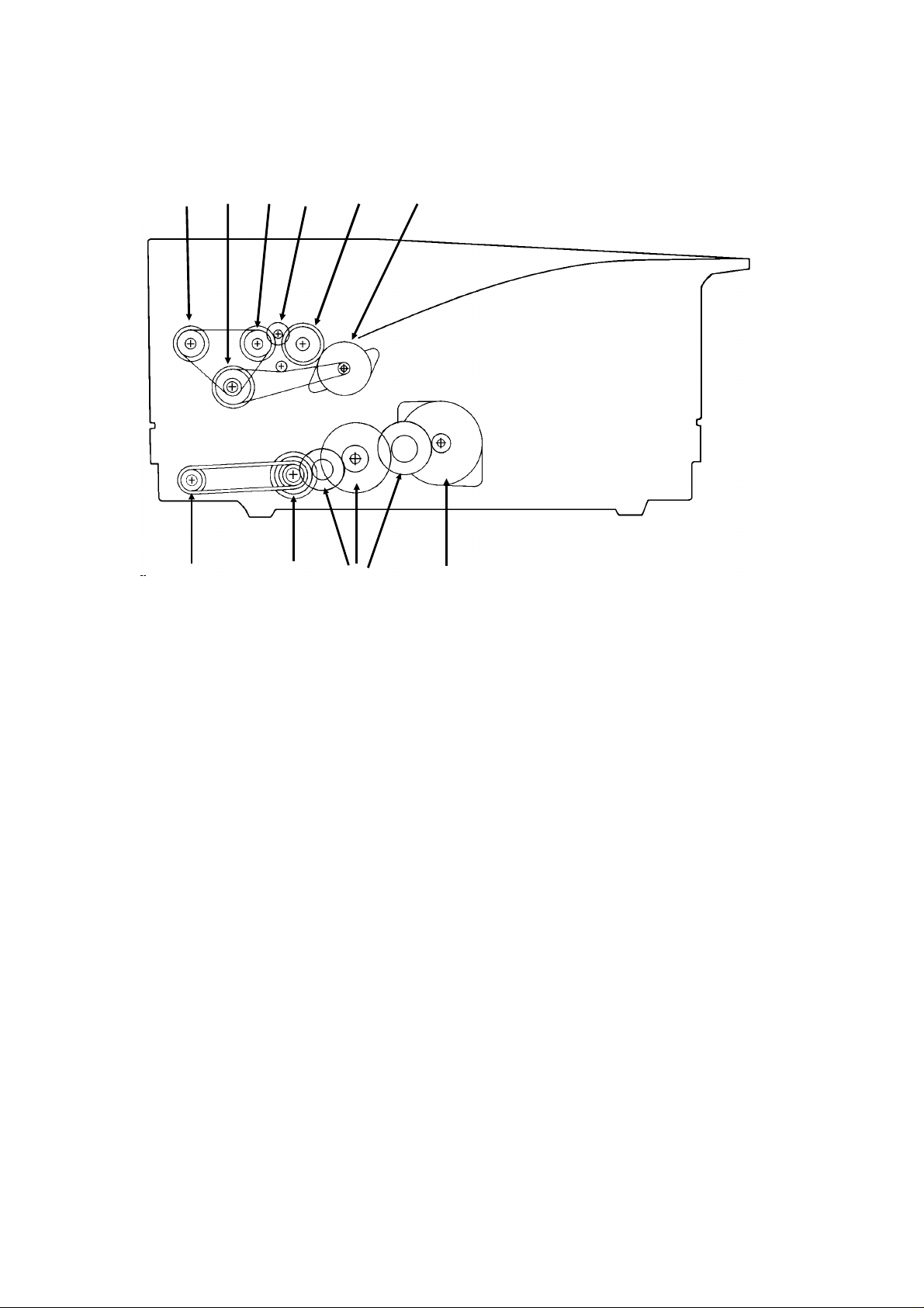
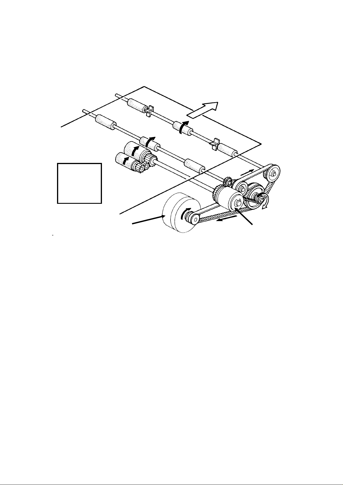
1.3.2. Drive Components
12 34 5 6
10
9
8
7
1. R2 Roller Drive Gear Drives the R2 roller.
2. Scanner Drive Gear Transfers drive from the Tx mo tor to th e
scanner and ADF.
3. R1 Roller Drive Gear Drives the R1 roller.
4. Document Feed Idle
Gear
5. ADF
Clutch/Document
Transfers drive from the Tx motor to the
document feed roller.
Drive the document feed roller, which feeds
the document into the scanner.
Feed Drive Gear
6. Tx Motor Drives the ADF and scanner.
7. Rx Motor Drives the printer.
8. Printer Drive Gears Tr ansfer Rx motor drive to the pr inter.
9. Platen Roller Drive
Gear
10. Feed-out Roller Drive
Gear
Drives the platen roller, which pulls the
thermal paper through the printer
Drives the feed-out roller, which feeds the
printed copy out of the machine.
1-6
2
4
11
OVERALL MACHINE INFORMATION November 30th, 1991
COM PONEN T LAYOUT
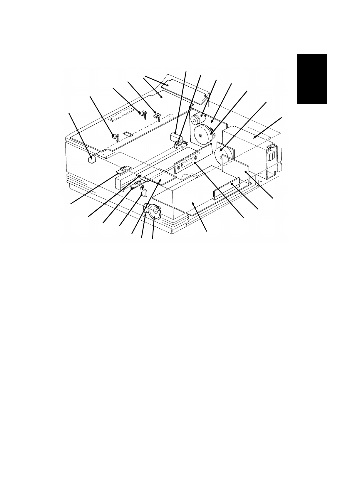
1.3.3. Electrical Components
1
23
22
21
20
3
5
6
1
19
18
17
16
15
14
13
9
10
12
7
8
Name Description No.
PCBs
FCU This board controls the machine. 11
MBU This board contains the system ROM and RAM
8
for storing system parameters such as bit switch
settings and programmed telephone numbers.
SBU This board co ntains the CCD. 10
OP-PORT This board controls the operation panel. 23
NCU This board c ontains relays and switches for
4
interfacing the machine to the telephone network
and the handset.
PSU This board sup plies power to the machine. 7
Xenon Lamp
This supplies power to the xenon lamp. 14
Driver
MOTORS
Tx Motor This drives the scanner. 5
Rx Motor This drives the printer. 6
Cutter Motor This drives the cutter. 1
1-7

November 30th, 1991 OVERALL MACHINE INFORMATION
COM PONEN T LAYOUT
Name Description No.
CLUTCHES
ADF Clutch This transfers drive fr om the tx motor to the
3
document feed roller.
SENSORS
Document Sensor This detects the presence of a document in the
22
feeder.
Scan Line Sensor This detects when a page is approaching th e
21
auto shading position.
Trailing Edge Sensor
This detects when the trailing edge of t he page is
passing the scan line.
20
Paper End Sensor This detects when the thermal paper has run out. 16
Printer Jam Sen-
This detect s jams in the printer. 18
sor
Cutter Sensor This monitors the operation of the cutter. 2
Cover Switch This detects whether the cover is open or closed. 15
OTHERS
Thermal Head This prints on the thermal paper. 17
SAF Memory Modules
Speaker This allows the user to listen to the condition of
These memory modu les each contain 1 Mbyte of
memory for storing fax messages.
9
12
the telephone lin e.
Xenon Lamp This lamp illuminates the document. 19
Battery This rechargeable battery backs up the SAF
13
memory when the main power is switched off.
1-8
OVERALL MACHINE INFORMATION November 30th, 1991
OVERALL SYSTEM C O NTROL
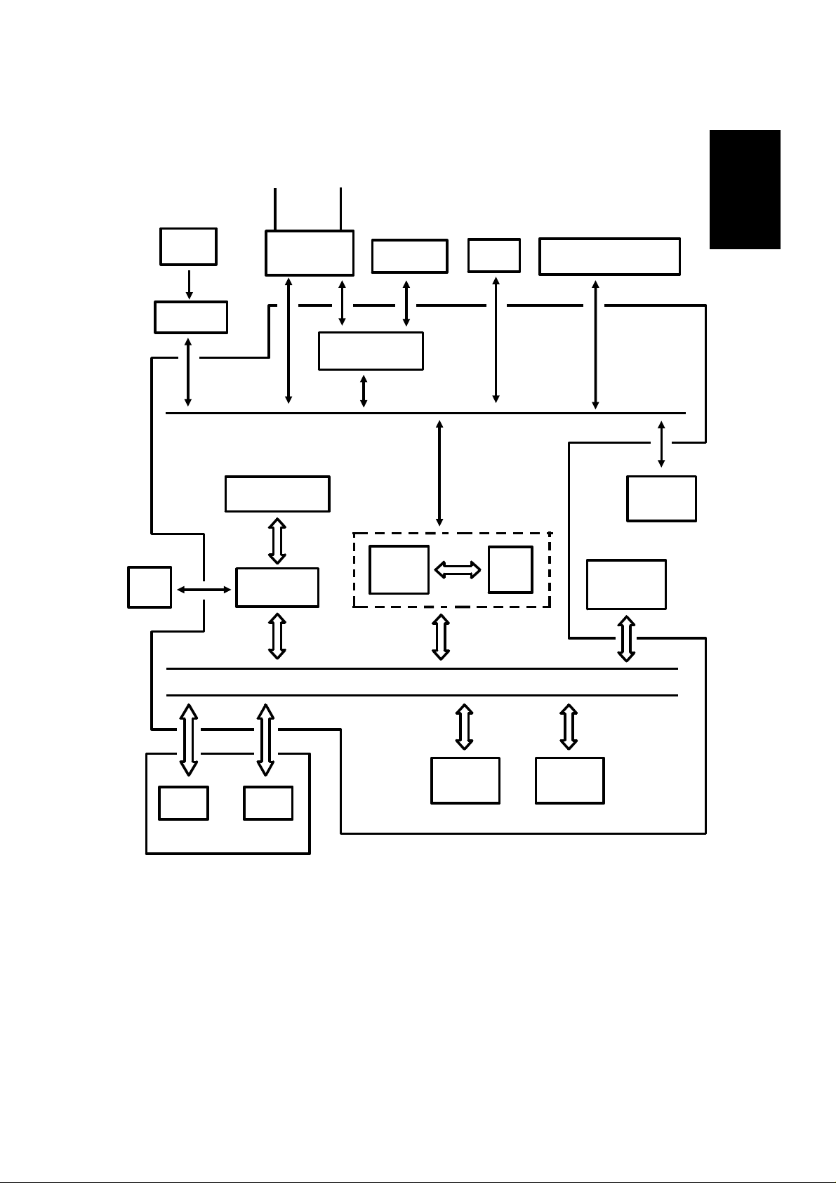
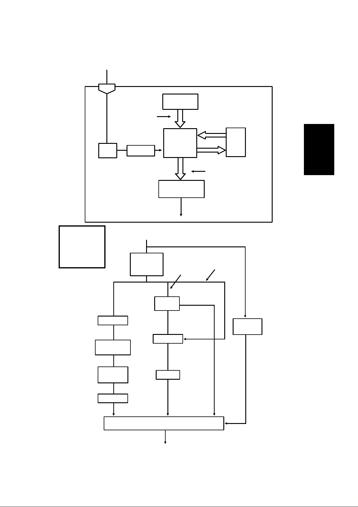
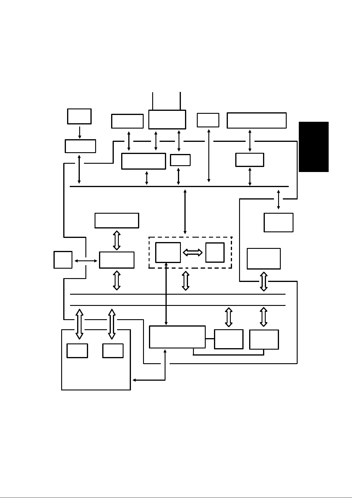
1.4. OVERALL SYSTEM CONTROL
HandsetLine
1
SBU
(CCD)
Scanner
Sensors
Operation
Panel
NCU
CONTROL SIGNALS
Video Processing
Memory
Video
Processor
Speaker
Modem AFE
CPU
PSU
Port
Scanner and Printer Drive
Components and Sensors
Thermal
Head
I/O
RS-232C
Interface
DATA AND ADDRESS BUS
SAF
Memory
RAMROM
ECM
Memory
FCU
MBU
The cpu on the FCU board controls the machine, as shown in the above
drawing.
There is no modem board in the m achine. The cpu performs the digital functions of a modem and carries out digital to analog conversion of facsimile
data. There is a separate analog modem chip (called the Modem AFE) which
does the rest of the modem operations.
1-9
November 30th, 1991 OVERALL MACHINE INFORMATION
VIDEO DATA PATH
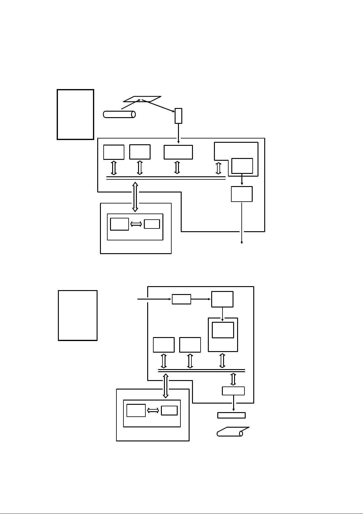
1.5. VIDEO DATA PATH
1.5.1. Transmission
Reference:
Group 3
Facsimile
Manual,
section
1-3-1
Xenon
Lamp
ECM
Memory
Line
Buffer
Original
SAF
Memory
RAM
FIFO
CCD
Analog Signal
Video
Processor
The fo llowing diagrams show
the data path for this model.
CPU
Modem
(Digital)
MODEM
AFE
FCU
Modem
(Analog)
1.5.2. Reception
Reference:
Group 3
Facsimile
Manual,
section
1-3-2
MBU
From the
Network
(via the NCU)
Line
Buffer
RAM
FCU
SAF
Memory
FIFO
Filter
HYBRID IC
Memory
ECM
Thermal
Head
Modem
(Analog)
Modem
(Digital)
CPU
I/O Port
To the
Network
(via the NCU)
MODEM
AFE
MBU
Thermal
Paper
1-10
OVERALL MACHINE INFORMATION November 30th, 1991
POWER DISTRIBUTION
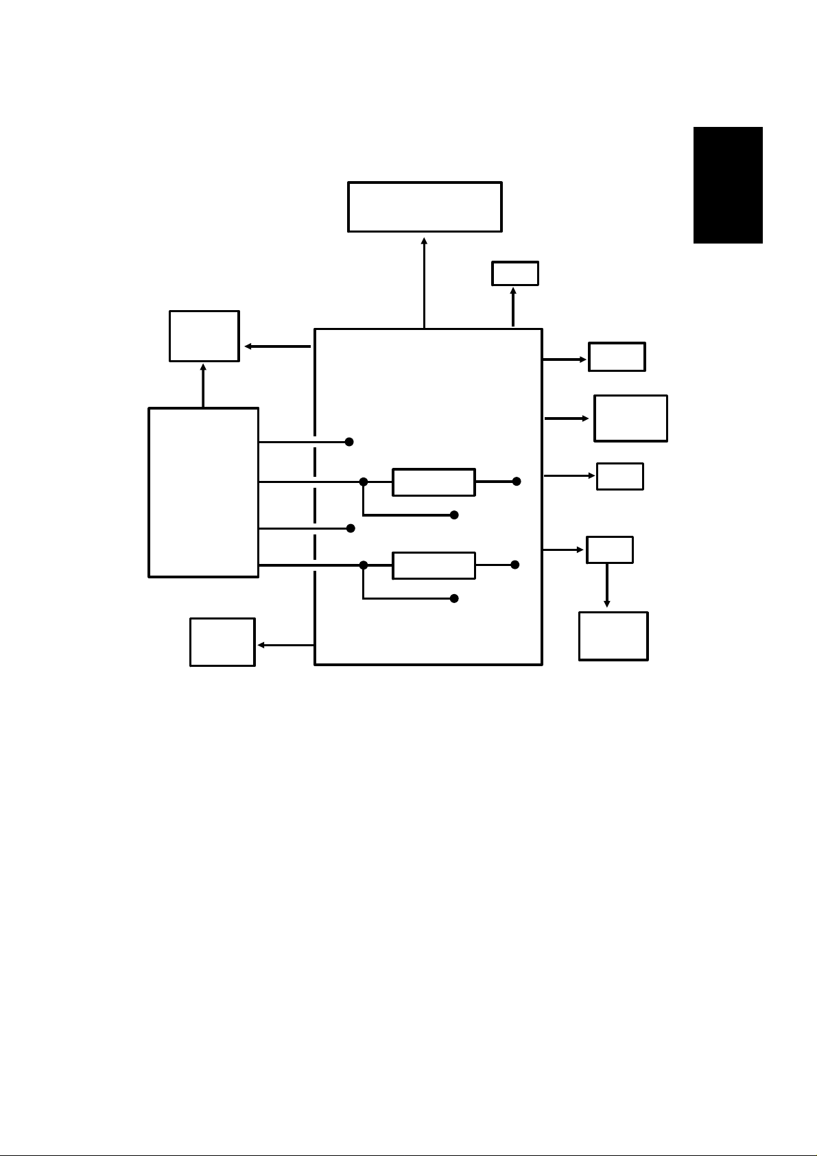
1.6. POWER DISTRIBUTION
1.6.1. Distribution Diagram
Motors, ADF Clutch
Xenon Lamp
+24VD
NCU
+5V
Thermal
+24VD
Head
+5V
+5V
+5V
+24VS
FCU
+5V
+5V
MBU
RS-232C
Interface
1
+5V
SBU
+12V
+5V
OPU
+5V
Scanner
Sensors
PSU
Printer
Sensors
+24VS
+24VD
-12V
+5V
+12V
Regulator
+24VS
+24VD
Regulator
- 5V
- 12V
The PSU supplies power to the machine through the FCU, except for the thermal head power, which it supplies directly. The FCU contains regulators
which generate other voltages needed by the machine.
There are two + 24V power supplies:
• + 24VS: This is always on when the main swit ch is on.
• + 24VD: This is switched on by the cpu when a ringing signal is de-
tected, or when the user presses the Start or Copy key. It is not interrupted if the cover s witch is opened ; however, printing stops and th e
document is fed out.
In some documentation for this model, + 24VD may sometimes be referred
to as + 24VA.
1-11
November 30th, 1991 OVERALL MACHINE INFORMATION
POWER DISTRIBUTION
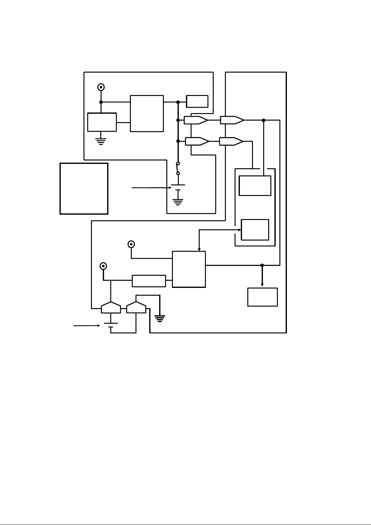
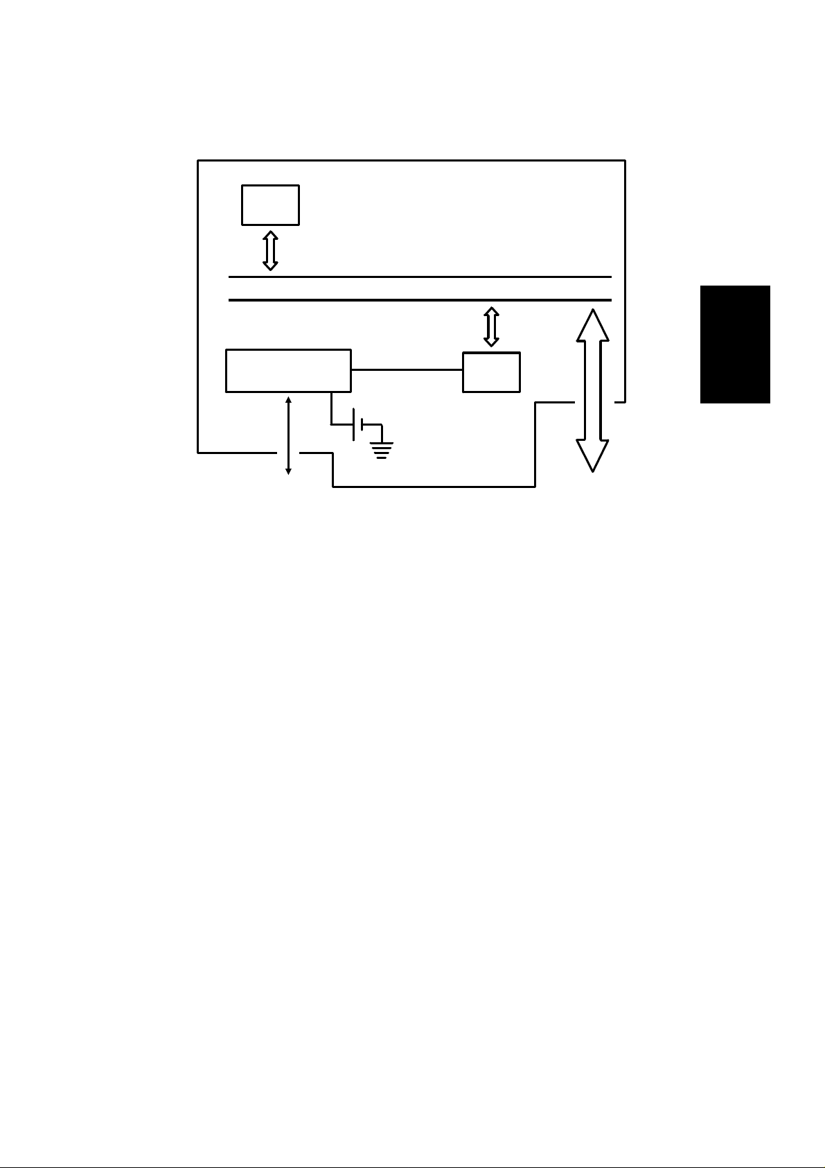
1.6.2. Memory Back-up Circuit
+5V
Voltage
Detector
Switching
Circuit
MBU
RAM
1-11 1-11
FCU
Reference:
Group 3
Facsimile
Manual,
sect io n 1-4-3,
Circuit type 1
+24V
5-1
[A]
+5V
Regulator
5-2
1-9
Battery
Switch
Battery
Switching
Circuit
1-9
Real Time
Clock
CPU
Memory
Monitor
SAF
Memory
[B]
Battery
The battery [A] on the MBU backs up the RAM on the MBU, which contains
system parameters. It also backs up the real time clock in the cpu. This battery is not rechargeable. CN1-9 tells the cpu whether the back-up power
(CN1-11) comes from the battery or from the + 5V supply.
A rechargeable battery [B] backs up the SAF memory and the real time clock
for 1 hour. When the main power is switched on, the + 24V supply charges
the battery. If there is data in the SAF, the battery also backs up the real time
clock, to preserve the MBU battery.
1-12
ADF Clutch
DETAILED SECTION DESCRIPTIONS November 30th, 1991
SCANNER
2. DETAILED SECTION DESCRIPTIONS
2.1. SCANNER
2.1.1. Mechanisms
1. Document Detection
Trailing Edge
Sensor
Scan Line Sensor
2
Document
Sensor
Separation
Plate
Feed
Roller
• The machines in this ser ies have an A4-width [8.3"] scanner. There is
Separation Rolle r
Pick-up Roller
no document width detector.
• The scanner contains a xeno n lamp.
• Th ere is no shutter mechanism.
Reference: Group 3 Facsimile Manual, section 2-1
2-1
November 30th, 1991 DETAILED SECTION DESCRIPTIONS
SCANNER
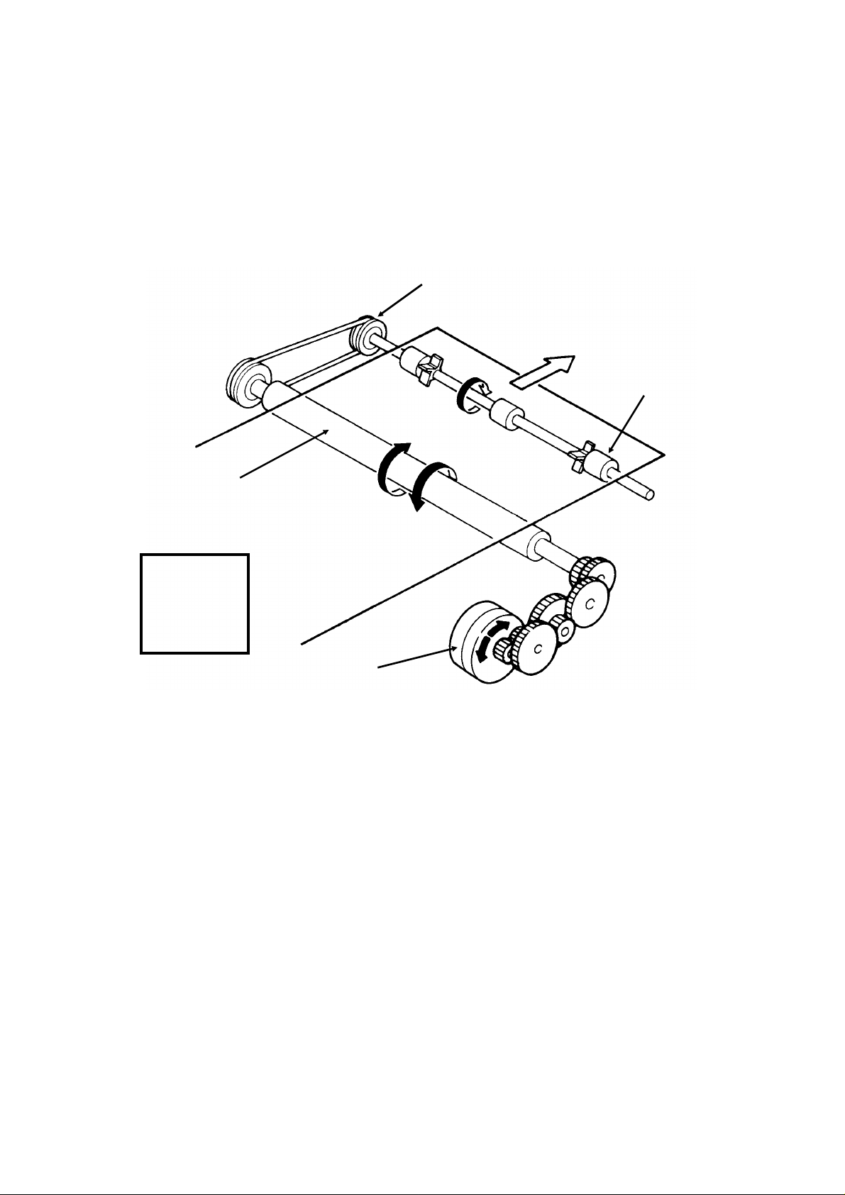
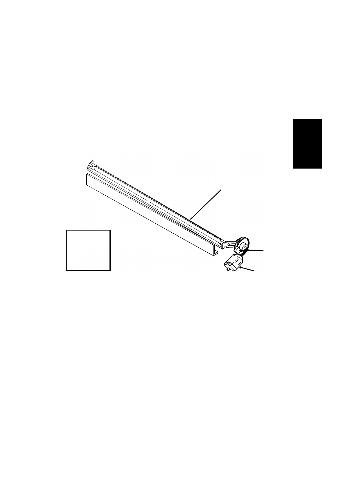
2. Pick-up and Feed
Mechanism
Refere nce :
Group 3
Facsimile
Manual,
sect io n 2-2-1.
Tx Motor
• This machine uses an electrical clutch mechanism with trailing edge sen-
ADF Clutch
sor.
• There is no manual feed.
Resolution
Standard - The tx moto r feeds the document at 7.7 lines/mm. The vid e o
proc essor executes OR pro cessing to convert the data into 3.85 lines/mm.
Detail - The tx motor feeds the docu ment at 7.7 lines/mm. There is n o OR
processing, and the data is transmitted at 7.7 lines/mm
Fine - The tx motor feeds the document and transmits data at 15.4 lines/mm.
If the other terminal cannot receive at this resolution, the tx motor feeds the
paper at 7.7 lines/mm, and the data is transmitted using Detail resolution.
Jam Conditions
The cpu detects a document jam if one of the fo llowing conditions occurs.
• The scan line sensor does not switch on within 3.5 s of the Star t key be-
ing pressed.
• The scan line sensor does not tu rn o ff after th e maximum docum e nt
length has been fed since it turned on.
• The scan line sensor switches on while the document sensor is off.
2-2
DETAILED SECTION DESCRIPTIONS November 30th, 1991
SCANNER
2.1.2. Video Data Processing
Output from the CCD
A
Auto Shading
Memory
WHITE
WAVEFORM
FEEDBACK
Peak
Hold
DATA
DC
Filter
Amplifier
A/D
Converter
CORRECTED
Data Processing
Circuits
2
Reference:
Group 3
Facsimile
Manual,
sect io n 2-3.
VIDEO
PROCESSOR
Corrected Data from the Auto Shading Circuit
Comparator
Background
Detection
OR
Processing
Gamma
Correction,
MTF
Edge
Detection
NON-EDGE
ELEMENTS
Reduction
Halftone
To the CPU
and Modem
Basic
Halftone
Process
EDGE
ELEMENTS
Error
Diffusion
Halftone
Process
Image/Text
Detection
Reduction
A
B
Process Selector
To CPU and Modem
2-3
B’
November 30th, 1991 DETAILED SECTION DESCRIPTIONS
PRINTER
2.2. PRINTER
2.2.1. Mechanisms
1. Paper Feed
Mechanis m
One-way Clutch
Feed-out
Roller
Platen Roller
Refere n ce:
Group 3
Facsimile
Manual,
sect i o n 3-4-1.
Rx Motor
The printer is an A4-width [8.3"] printer.
Resolution
Standard - Each received line is printed 4 times
Detail - Each received line is printed twice
Fine - Each received line is printed once.
2-4
DETAILED SECTION DESCRIPTIONS November 30th, 1991
PRINTER
Jam Detection
The cpu detects a copy jam if one of the following conditions occurs:
• If the printer jam sensor still does not detect paper after the minimum
cop y length has been fed since the start of printing.
• Between pages of a multipage printout, the printer jam sensor switches
off. A jam is detected if the sensor does not switch back on after the
minimum copy length has been fed since it turned off.
• If the printer jam sensor still detects paper after the end of the feed-out
procedure for the last page of a print run.
2. Cutting
Cutter
Blade
2
Reference:
Group 3
Facsimile
Manual,
sect i o n 3-6.
Cutter
Sensor
Cutter
Motor
The cutter mechanism is exactly as described in section 3-6 of the Group 3
Facsimile Manual.
3. Cutter Jam Detectio n
A cutter jam is detected if one of the following conditions occurs:
• If the cutter sensor do es not open within 0.25 s after the cutter starts to
move
• If the cutter sensor stays open for more than 1.0 s
If a cutter jam is detected, the cutter motor reverses to return the cutter to the
standby position.
2-5

November 30th, 1991 DETAILED SECTION DESCRIPTIONS
PRINTER
2.2.2. Circuits
1. Video Data Processing
• Smoothing is as described in section 3-5-1 of the Group 3 Facsim ile
Manual
• There is no reduction.
2. Thermal Head
Both machines use an A4-width [8.3"] thermal head. Refer to sec tion 3- 5- 2 of
the Group 3 Facsimile Manual for a circuit diagram.
The operation of the thermal head is as explained in the Group 3 Facsimile
Manual, except that when printing a line, blocks 0 and 1 are printed together,
then blocks 2 and 3 are printed together.
The data are p rinted as exp lained in section 3-5-3 of the Group 3 Facsimile
Manual. In Fine mode, the pulse width is automatically increased by 50%.
The machine prevents overheat protection by adjusting the pulse width in accord ance with the temperature measured by the thermistor on the thermal
head.
Reference: Group 3 Facs imile Man ual, s ectio ns 3-5-1, 3-5-2, and 3-5-3.
2-6
DETAILED SECTION DESCRIPTIONS November 30th, 1991
PCBs AND THEIR FUNCTIONS
2.3. PCBs AND THEIR FUNCTIONS
2.3.1. FCU
HandsetLine
SBU
(CCD)
Scanner
Sensors
Operation
Panel
Speaker
Modem AFE
CONTROL SIGNALS
Video Processing
Memory
Video
Processor
NCU
CPU
HIC
PSU
FCU
I/O
Port
Scanner and Printer Drive
Components and Sensors
2
Drivers
Thermal
Head
RS-232C
Interface
MBU
DATA AND ADDRESS BUS
Memory Back-up
Control
SAF
Memory
ECM
Memory
RAMROM
2-7

November 30th, 1991 DETAILED SECTION DESCRIPTIONS
PCBs AND THEIR FUNCTIONS
1. CPU (AFSP)
• 65C02 compatible microprocessor
• Interrupt control
• DMA control
• Data compression and reconstruction (high speed MH coding for 4.5-
second scanning)
• Modem (digital operations)
• Real time clock (battery backed-up)
• Memory control
• Control of all mechanisms (directly or through other chips)
• NCU control (through the I/O Port)
2. I/ O Port (LIOP)
• Clock control
• Sensor monitoring (including A/D conversion where necessary)
• Tone detection
• Thermal head control
• Tx/Rx/cutter motor drive control
• Operation p anel control
3. Modem Analog Front End (Modem AFE)
• Modem (analog operations)
• Attenuati on
4. Video Processor (VPP)
• Analog/digital video signal processing
5. Driver (MFPD)
• Tx/Rx/cutter motor drive
6. Driver Array
• Xenon lamp/ADF clutch drive
7. Hybrid IC (HIC)
• Gain control for rx data
• Filters
8. RAM
• 128k for ECM (no bac k-up)
• 256k SAF memory (with battery back-up)
2-8
DETAILED SECTION DESCRIPTIONS November 30th, 1991
PCBs AND THEIR FUNCTIONS
2.3.2. MBU
System
ROM
DATA AND ADDRESS BUS
Memory Back-up
Control
+
To/From
FCU
1. System ROM
• Contains the software to run the machine
MBU
2
System
RAM
To/From
FCU
2. System RAM
• 32k SRAM and 32k PSRAM for parameter storage, line buffer, FIFO,
SAF memory administration
The SRAM is backed up by the battery on the MBU
2-9
November 30th, 1991 DETAILED SECTION DESCRIPTIONS
PCBs AND THEIR FUNCTIONS
2.3.3. SBU
Analog Video
To the FCU
Drive Clocks
From the FCU
Drivers
CCD
+12V
+12V
Inverter
Amplifier
2.3.4. OPU
LCD Panel
Auxiliary Operation
Panel Controller
+
Operation Panel
Keys
Operation Panel
Controller
Emitter
Follower
Operation Panel
LEDs
SBU
Output
from the
Scanner
Sensors
Serial Interface
To/From FCU
2-10
DETAILED SECTION DESCRIPTIONS November 30th, 1991
PCBs AND THEIR FUNCTIONS
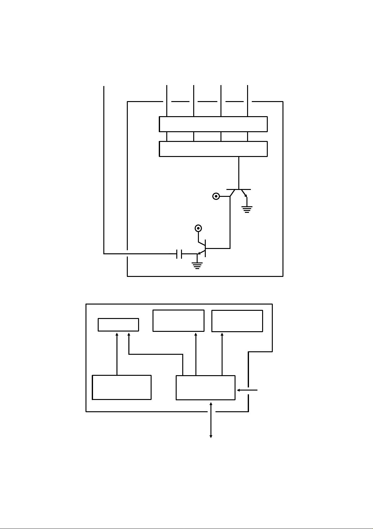
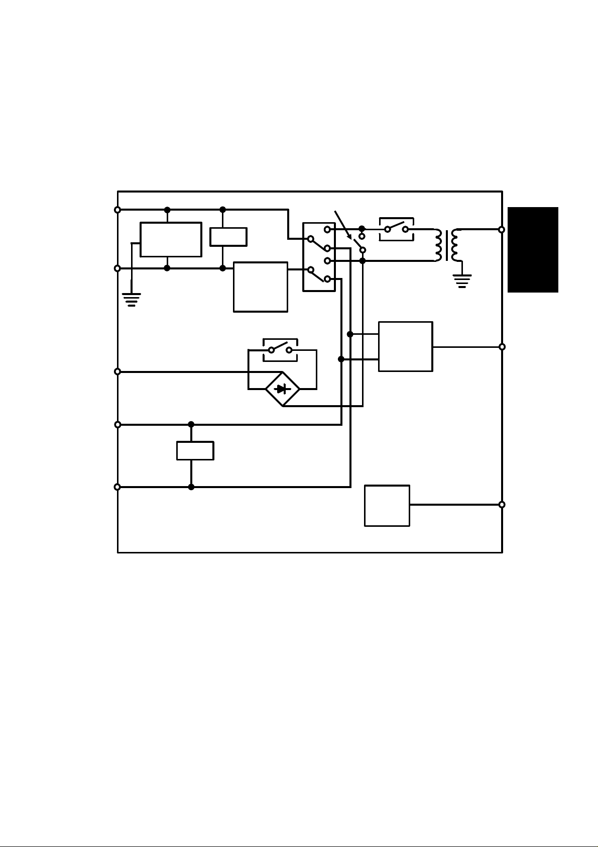
2.3.5. NCU
1. PCB Block Diagram
L1
L2
GS
T2
T1
Protection
Circuit
FG
To
Handset
To
Network
Filter
Filter
Line
Current
Detector
Gs Relay
Di Relay
Oh
Relay
Ds Relay
Ringing
Signal
Detector
Relay
Driver
Tx/Rx Data
To/From FCU
2
To
FCU
From FCU
NCU
• For simplification, relay drive signals and detector outputs to/from the
FCU are not shown on this diagram.
• In the above diagram, the relays are shown in the standby position for
Auto Receive (Fax) Mode.
2-11

November 30th, 1991 DETAILED SECTION DESCRIPTIONS
PCBs AND THEIR FUNCTIONS
2. Signal and Jumper Settings
The following table shows the jumper positions for each country, and the
status of the relay control signals (CN3-A7, B7, and A8). The country is selected by the Country Code for NCU Parameters (NCU Parameter 00; use
Function 96).
Standby Mode After Ringing Detection Jumpers
CN3-A7CN3-B7CN3-A8CN3-A7CN3-B7CN3-A8TB1
& 2TB3TB8TB4TB5TB6JP1
Germany X X X O O X OXXXXXX
UK XOXOOXOXXXXXX
Italy O O X O O X OXXXXXX
Austria OOXXXXOXXOXXX
BelgiumOOXXXXOXXXXXX
DenmarkOOXXXXOXXXXOX
Finland O O O O O X O X X X X X X
Ireland O O X X X O OXXXXXX
Norway X O X X X O OXXXXXO
SwedenXXXXXXOXXXXXX
Switz. XOXXXXOOOXXXX
PortugalOOXXXXOXXXXOX
Holland O O X X X O OXXXOXX
Hg KongXOXOOXOXXXXXX
S. Africa O O O O O X OXXXXXX
AustraliaXOXOOXOXXXXXX
N. Z’landXOXOOXOXXXXXX
Israel O O X O O X OXXXXXX
Spain OOXXXXOXXXXOX
Singapore O O X O O X OXXXXXX
Malaysia X O X O O X O X X X X X X
Key
Signal Status: O = High, X = Low
Jumper Settings: O = Closed, X = Open
2-12
 Loading...