

Ricoh fax4000 Service Manual

FAX UNIT
(Machine Code: B383)
This manual explains the Fax Unit, as well as the following.
❒
EXSAF (Machine Code: A818)
❒
HDD (Machine Code: A841)
❒
PMU (Machine Code: A818)
❒
ISDN (Machine Code: A816)
❒
Handset (Machine Code: A841)
❒
Stamp (Machine Code: A563)
August 28, 2000
Subject to change

28 August, 2000 SPECIFICATIONS
1. OVERALL MACHINE INFORMATION
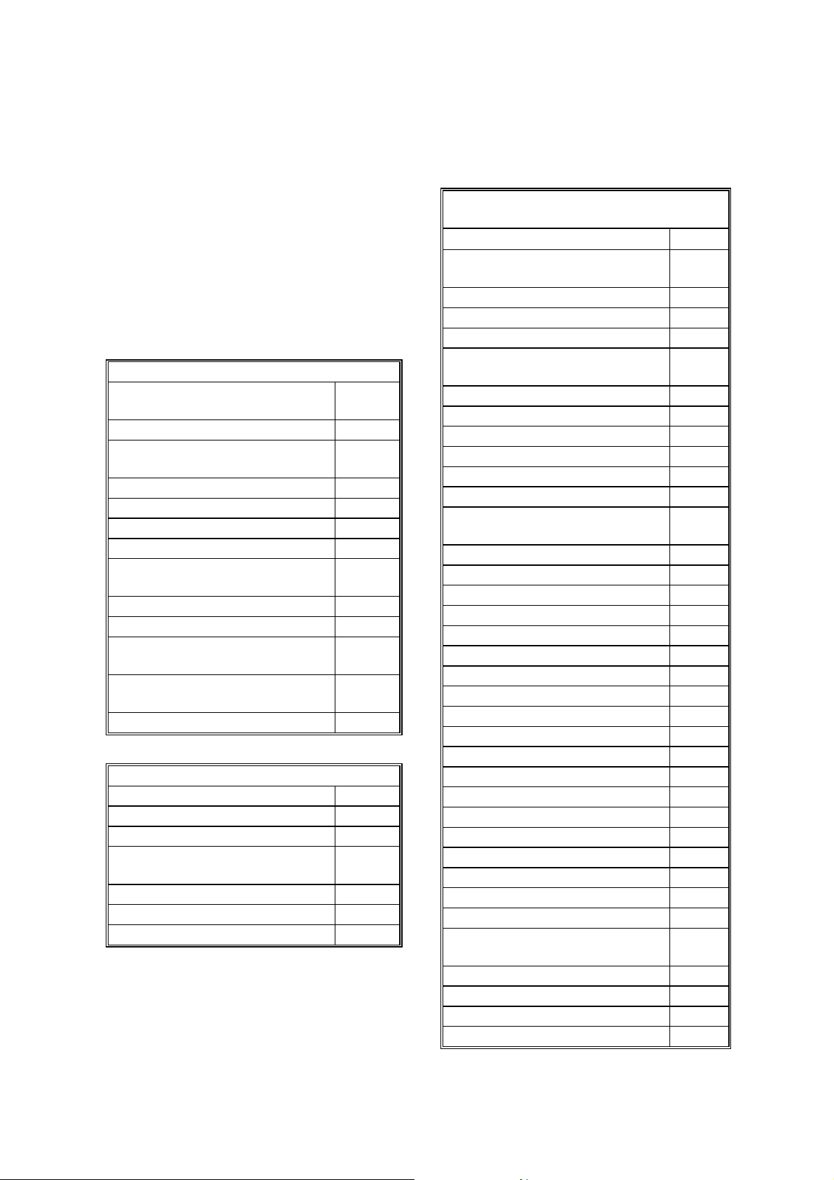
1.1 SPECIFICATIONS
Type
Desktop type transceiver
Circuit
PSTN, PABX, ISDN (optional)
Connection
Direct couple
Original Size (Book)
Maximum Length: 432 mm [17 ins]
Maximum Width: 297 mm [11.7 ins]
Original Size (ADF)
Maximum: A3, 11” x 17”
” x 8
Minimum: B5, 5
Scanning Method
Flat bed, with CCD
Scan Width
210 mm [8.64 ins] ± 1% (A4)
216 mm [8.5 ins] ± 1% (8.5" x 11")
256 mm [10.2 ins] ± 1% (B4)
279 mm [11.0 ins] ± 1% (11" x 17"r)
296 mm [12.2 ins] ± 1% (A3)
Resolutions
8 x 3.85 lines/mm (G3 only)
8 x 7.7 lines/mm (G3 only)
8 x 15.4 lines/mm (G3 only)
16 x 15.4 lines/mm (G3 only)
200 x 100 dpi
200 x 200 dpi
400 x 400 dpi
Note:
To use the 8 x 15.4 lines/mm, 16 x 15.4
lines/mm and 400 x 400 dpi resolutions, an
optional PMU (page memory) is required.
1/2
1/2
”
Memory Capacity
ECM: 128 Kbytes
SAF:
Standard: 2 Mbytes (160 pages)
With optional memory board (EXSAF):
6 Mbytes (480 pages)
With optional HDD:
80 Mbytes (3000 pages)
Measured using an ITU-T #1 test document
(Slerexe letter)
Compression
MH, MR, MMR, SSC
JBIG (PMU is required)
(MMR only with ECM and G4)
SAF storage for memory tx: MMR and raw
data
Protocol
Group 3 with ECM
Group 4 (ISDN unit required)
Modulation
V.34, V.17 (TCM), V.29 (QAM),
V.27ter (PHM), V.21 (FM)
Data Rate (bps)
G3:
33600/31200/28800/26400/24000/21600/
19200/16800/14400/12000/9600/7200/4800
/2400, Automatic fallback
G4 (option): 64 kbps/56 kbps
I/O Rate
With ECM: 0 ms/line
Without ECM: 2.5, 5, 10, 20, or 40 ms/line
Overall
Information
Transmission Time
G3: 3 s at 28800 bps; Measured wit h G3
ECM using memory for an ITU-T #1 test
document (Slerexe letter) at 8 x 3.85 l/mm
resolution
G4 (option): 3 s at 64 kbps; Measured with
an ITU-T #1 test document (Slerexe letter)
at 200 x 200 dpi resolution
1-1
FEATURES 28 August, 2000
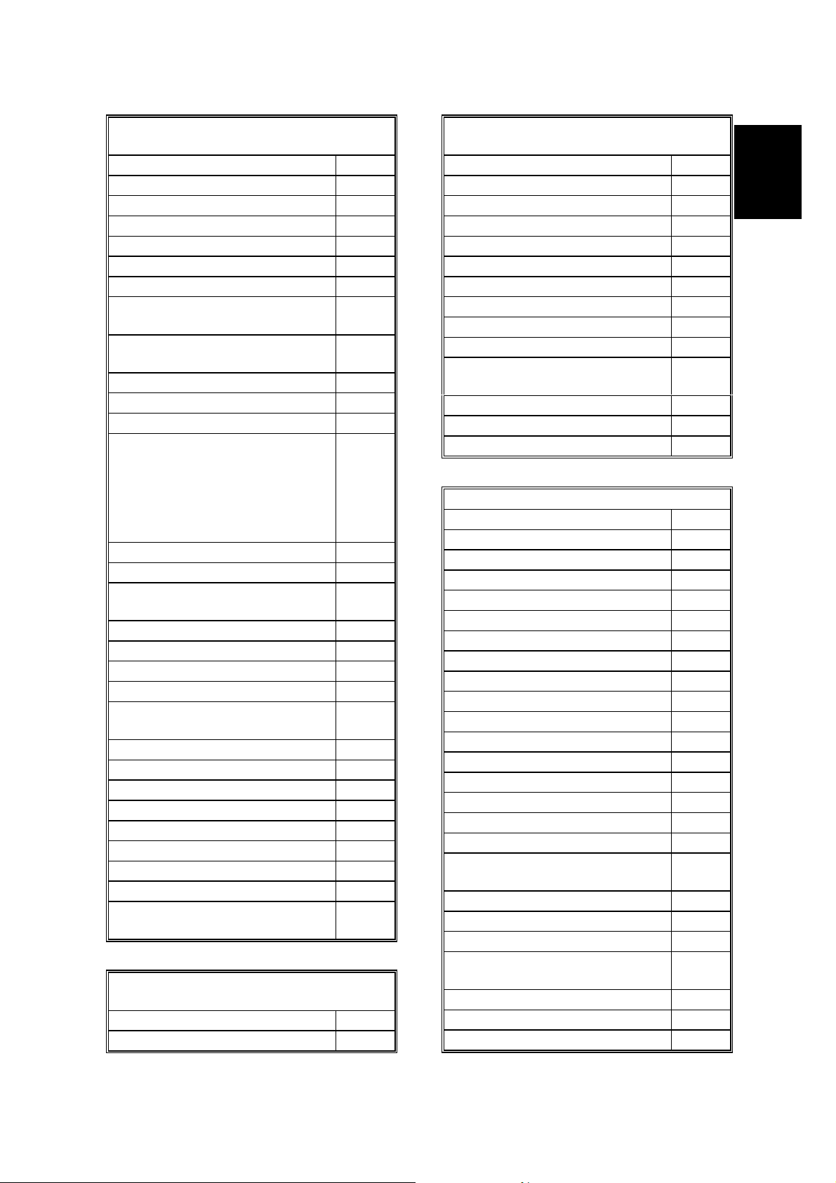
1.2 FEATURES
1.2.1 FEATURES LIST
KEY:
O = Used, X = Not Used,
A = Optional EXSAF required
B = Optional HDD required
C = Optional PMU required
D = Optional ISDN unit required
E = Optional STAMP unit
Video Processing Features
Automatic image density
selection
Contrast O
Halftone
(Basic & Error Diffusion)
MTF O
Reduction before tx (B4 -> A4) O
Reduction before tx (A3 -> B4) O
Reduction before tx (A3 -> A4) O
Scanning Resolution –
Standard
Scanning Resolution – Detail O
Scanning Resolution – Fine C
Scanning Resolution –
Superfine
Smoothing to 400 x 400 dpi
when printing
JBIG compression C
Communication Features – Automatic
V.34 communication O
AI short protocol O
Automatic fallba ck O
Automatic redialing
(Memory tx only)
Confidential Reception A
Dual Access O
Substitute reception O
O
O
O
C
O
O
Communication Features - User
Selectable
90° Image Rotation before tx
Action as a transfer
broadcaster
AI Redial (last ten numbers) O
Answering machine interface X
Authorized Reception O
Automatic dialing
(pulse or DTMF)
Auto Document O
Automatic Voice Message X
Batch Transmission O
Book Original tx O
Broadcasting O
Chain Dialing O
Communication Record
Display
Confidential ID Override O
Confidential Reception A
Confidential Transmission O
Direct Fax Number Entry O
Economy Transmission O
Fax on demand X
Forwarding A
Free Polling O
Groups (9 groups) O
Group Transfer Station A
Hold X
ID Transmission O
Immediate Redialing O
Immediate transmission O
Keystroke Programs O
Length Reduction O
Memory transmission O
Multi-step Transfer A
Next Transfer Station X
Non-standard original size
transmission
OMR X
On Hook Dial O
Ordering Toner X
Page Count O
O
A
O
O
O
1-2
28 August, 2000 FEATURES
Communication Features - User
Selectable
Page separation mark O
Parallel memory transmission O
Personal Codes O
Personal Codes with Conf. ID X
Partial Image Area Scanning X
Polling Reception O
Polling Transmission O
Polling tx file lifetime in the
O
SAF
Quick Dial
O
(Standard: 56 stations)
Reception modes (Fax, Tel) O
Remote control features X
Remote Transfer X
Resolutions available for
reception
Standard
Detail
Fine (16 x 15.4 l/mm only)
Superfine
O
O
C
C
Restricted Access O
Secured Polling O
Secured Polling with Stored ID
O
Override
Secure Transmission X
Send Later O
SEP/SUB/PWD O
Silent ringing detection X
Speed Dial
O
(Standard: 100 stations)
Stamp E
Telephone Directory O
Tonal Signal Transmission O
Transfer Requ est O
Transmission Deadline (TRD) X
Turnaround Polling X
Two-step Transfer X
Two in one O
Voice Request
X
(immed. tx only)
Communication Features -
Service Selectable
AI Short Protocol O
Auto-reduction override option O
Communication Features -
Service Selectable
Busy tone detection O
Cable Equalizer O
PSTN O
ISDN D
Closed Network (rx) O
Continuous Polling Reception O
Dedicated tx parameters O
ECM O
EFC X
Inch-mm conversion before tx O
mm-inch selection when
O
printing
Page retransmission times O
Protection against wrong conn. O
Short Preamble X
Other User Features
Area code prefix X
Center mark O
Checkered mark O
Clearing a memory file O
Clearing a polling file O
Clock O
Confidential ID A
Counters O
Daylight Saving Time O
Destination Check X
Direct entry of names O
File Retention Time O
File Retransmission O
Function Programs (F1 – F5) O
Hard Disk Filing System X
ID Code O
Label Insertion ("To xxx") O
Language Selection SP
mode
Manual service call O
Memory Lock A
Modifying a memory file (tx) O
Multi Sort Document
A
Reception
Own telephone number O
Energy Saver O
Print density control X
Overall
Information
1-3
FEATURES 28 August, 2000
Other User Features
Printing a memo ry file
SP
mode
RDS on/off O
Reception Mode Switching
X
Timer
Reception time printing O
Remaining memo ry indicator O
Reverse Order Printing O
RTI, TTI, CSI O
Speaker volume control O
Specified Cassette Selection O
Substitute reception on/off O
Telephone line type O
Toner Saving Mode X
TTI/CIL on/off O
User Function Keys (5 keys) O
User Parameters O
Wild Cards O
Reports - Auto ma tic
Charge Control Report X
Communication Failure Report O
Confidential File Report A
Error Report O
Fax On Demand Report X
Memory Storage Report O
Polling Clear Report O
Polling Reserve Report O
Polling Result Report O
Power Failure Report O
Journal O
Toner Cassette Order Form X
Transfer Result Report A
Transmission Result Report O
Reports - User-initiated
Authorized Reception List O
Charge Control Report X
File List O
Forwarding List A
Group List O
Hard Disk File List X
Personal Code List O
Keystroke Program List O
Reports - User-initiated
Quick Dial/Function Key Label O
Quick Dial List O
Specified Cassette Selection
X
List
Speed Dial List O
TCR/Journal O
Transmission Status Report X
User Function List X
User Parameter List O
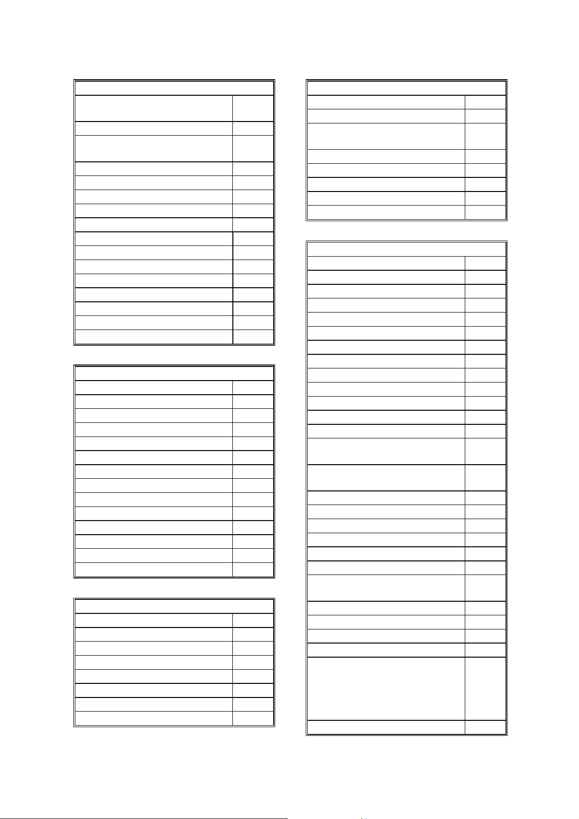
Service Mode Features
Back-to-back test O
Bit switch programming O
Buzzer test O
Cable equalizer O
Comm. parameter display O
Counter check O
Country code O
DTMF tone test O
Echo countermeasure O
Effective term of service calls O
Error code display O
Excessive jam alarm O
File Transfer O
Hard Disk Utilities
(Format etc.)
A and
B
LCD contrast adjustment SP
mode
Line error mark X
Memory file printout (all files) O
Modem test (includeV.34 / V.8) O
NCU parameters O
Periodic service call O
PM Call O
Printing all communication
O
records kept in me mory
Protocol dump list O
RAM display/rewrite O
RAM dump O
RAM test O
RDS
- RAM read/write
- Dial data transfer
O
O
(Quick/Speed)
- Software transfer
O
Ringer test O
1-4

28 August, 2000 FEATURES
Service Mode Features
ROM version display
O
(FCU and Modem)
Serial number O
Service monitor report O
Service station number O
Software Download O
Software Upload O
Modem Software Download O
SRAM data backup and
O
restore
System parameter list O
Technical data on the Journal O
Overall
Information
1-5

FEATURES 28 August, 2000
1.2.2 CAPABILITIES OF PROGRAMMABLE ITEM S
The following table shows how the capabilitie s of each programmable item will
change after the optional function upgrade card is installed.
With optional
Item Standard
Maximum number of memory files 200 1000
Maximum number of destinations per file 200 1000
Maximum number of destinations overall 500 2000
Maximum number of pages overall 160 480 (HDD: 3000)
Number of Quick Dials 56 56
Number of Speed Dials 100 1000
Number of Groups 9 30
Maximum number of destinations per
Group
Maximum number of destinations dialed
from the ten-key pad overall
Maximum number of programs
(programmed in 56
Quick Dial keys)
Maximum number of Auto Documents
(programmed in 6
Quick Dial keys)
Maximum number of communication
records for the Journal stored in the
memory
Maximum number of addresses specified
for features such as Authorized
Reception and Specified Cassette
Selection
Maximum number of user function keys 5 5
Maximum number of personal codes 20 50
200 200
100 1000
56
6
200 900
30 50
memory board
(EXSAF)
56
(programmed in 56
Quick Dial keys)
18
(programmed in 18
Quick Dial keys)
1-6
28 August, 2000 OVERALL MACHINE CONTROL
1.3 OVERALL MACHINE CONTROL
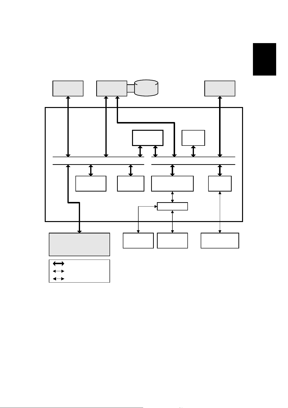
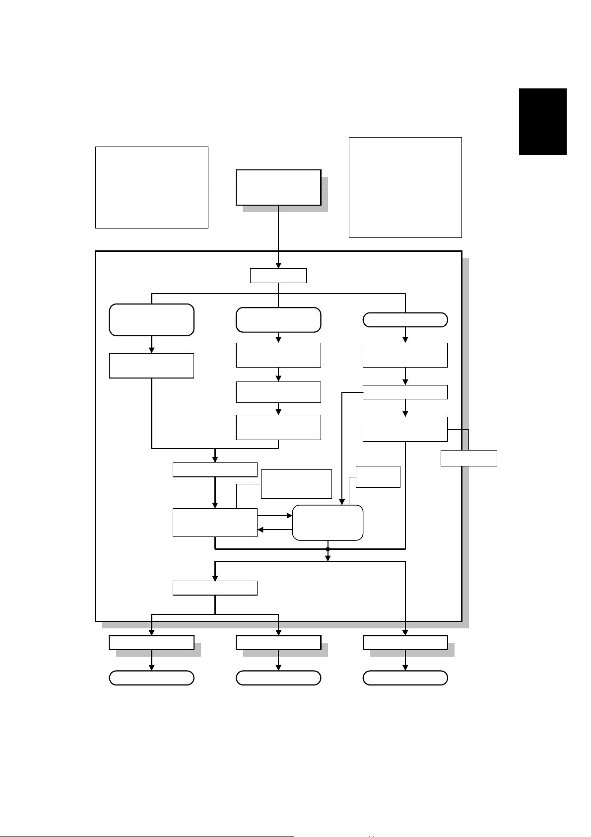
1.3.1 SYSTEM CONTROL
Overall
Information
ISDN
CPU BUS
Flash ROM
(2MB)
EXSAF
Board
SRAM
(128kB)
80MB
HDD
FCU
SCP
DMA BUS
MN195003MFL
Modem
Analog Circuit
PMU
Board
DRAM
(6MB)
VPC
<Service Tools>
Data Copy Tool
Flash Memory Card
Bus Interface
Parallel Interface
Serial Interface
Monitor
Speaker
NCU
Base copier
B383V500.WMF
1-7

OVERALL MACHINE CONTROL 28 August, 2000
The basic fax unit consists of two PCBs: an FCU and an NCU.
The FCU controls all the fax communications and fax features, in cooperation with
the base copier's main board. The NCU switches the analog line between the fax
unit and the optional external telephone.
Fax Options
1. ISDN unit: This allows the fax unit to communicate over an ISDN (Integrated
Services Digital Network) line.
2. EXSAF board: This expands the SAF memory capacity to hold up to 6MB of
received data or data for transmission. Also, some additional features become
available. In addition, this expands the system's SRAM capacity to hold
programmed telephone numbers, communication records, etc.
3. PMU board: This expands the page memory capacity to 4MB to enable 400 dpi
communications. Also, JBIG compression becomes available.
4. Hard Disk: This expands the SAF memory capacity to 80MB. The EXSAF is
required to install this option.
1.3.2 POWER DISTRIBUTION AND CONTROL
The FCU power is supplied from the base copier (+24V, +12V, -12V, and +5VE)
and PSU (+5V). Refer to the base copier's service manual for details.
1.3.3 MEMORY BACK-UP
The system parameters and programmed items in the SRAM on the FCU and the
EXSAF board are backed up by batteries (long-term backup), in case the base
copier's main switch is turned off.
The SAF memory (DRAM) on the FCU and the EXSAF board are backed up by
rechargeable batteries for 1 hour.
1-8
28 August, 2000 VIDEO DATA PATH
1.4 VIDEO DATA PATH
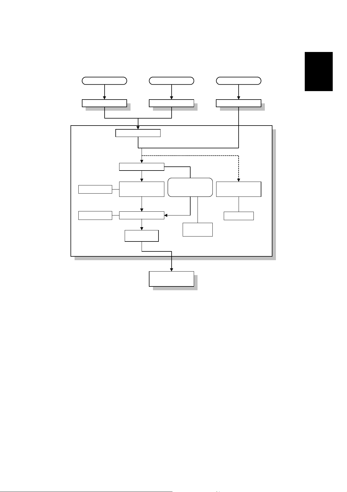
1.4.1 TRANSMISSION
Immediate Tx
Memory Tx
Auto Shading
Gamma Correction
MTF
Graduation Processing
Main Scan Reduction
- 400 to 200 dpi
Thresholding
Base copier
VPC
Auto Shading
Gamma Correction
MTF
Graduation Processing
Main Scan Reduction
- 400 to 200 dpi
- Inch-mm Conversion
- A3 to B4, A3 to A4, B4 to A4
Thresholding
Overall
Information
Memory Tx
without image
(DCMMR)
FCU
rotation
SCP
SAF Memory
SCP
(DCR)
Modem
Memory Tx
with Image Rotation
SCP SCP
Page Memory
(Rotation)
SCP
(DCMMR)
Decompression
Compression
(Main Scan Reduction)
PMU Board
QM-CORDER
(Optional)
Immediate Tx
Page Memory
SCP
(DCR)
JBIG
Compression
Compression
NCU CiG4 CiG4
Analog G3 ISDN G3 ISDN G4
1-9
A383V501.WMF

VIDEO DATA PATH 28 August, 2000
Memory Transmission and Parallel Memory Transmission
The mainframe's scanner scans the original at the selected resolution in inch
format. The mainframe processes the data and transfers it to the FCU.
NOTE: When scanning a fax original, the mainframe uses the MTF and
thresholding parameter settings programmed in the fax unit’s scanner
bit switches, not the copier's SP modes.
Then, the FCU converts the data to mm format, and compresses the data in
MMR+raw format to store it in the SAF memory. If image rotation is possible, the
image is rotated in page memory before com pression.
At the time of transmission, the FCU decompresses the stored data, then recompresses and/or reduces the data if necessary for transmission. Either the NCU
or CiG4 (optional) transmits the data to the line.
Immediate Transmission
The mainframe's scanner scans the original at the resolution agreed with the
receiving terminal. T he mainframe video processes the data and transfers it to the
FCU.
NOTE: When scanning a fax original, the mainframe uses the MTF and
thresholding parameter settings programmed in the fax unit’s scanner bit
switches, not the copier's SP modes.
Then the FCU stores the data in page memory, and compresses the data for
transmission. Either the NCU or CiG4 (option al) transmits the data to the line.
JBIG Transmission
• Memory transmission: With memory transmission, if the receiver has JBIG
compression, the data goes from the SCP (DCR) to the PMU for JBIG
compression. Then either the NCU or CiG4 (ISDN unit) transmits the data to the
line.
• Immediate transmission: With immediate transmission, if the receiver has JBIG
compression, the data goes from the page memory to the PMU for JBIG
compression. Then either the NCU or CiG4 (optional) transmits the data to the
line.
1-10
28 August, 2000 VIDEO DATA PATH
1.4.2 RECEPTION
Analog G3 ISDN G3 ISDN G4
NCU CiG4 CiG4
FCU
Decompression
Image Rotation
Modem
SAF Memory
SCP
(DCR)
Page Memory
VPC
PMU Board
QM-CORDER
(Optional)
JBIG
compression
Overall
Information
SCP
(DCR)
Error Check
Base copier
B383V502.WMF
First, the FCU stores the data from either an analog line or an ISDN line to the SAF
memory. (The data goes in parallel to the SCP, and is checked for error
lines/frames.)
The FCU then decompresses the data and transfers it to page memory. If image
rotation is possible, the image is rotated in the page memory. The data is
transferred to the mainframe.
JBIG Reception
When the machine receives data compressed with JBIG, the data is sent to PMU
for decompression. Then the data is stored in the page memory, and transferred to
the mainframe.
1-11

28 August, 2000 SERVICE CALL CONDITIONS
2. DETAILED SECTION
2.1 SERVICE CALL CONDITIONS
The fax unit makes an automatic service call when an SC code other than the
following is informed from the base copier.
NOTE: The service station’s f ax number has to be programmed in advance, or the
machine cannot make a service call.
Exceptions
Address (H) Definition Default SC code
480A30 1st SC code - High byte (BCD) 09
480A31 1st SC code - Low byte (BCD) AA
480A32 2nd SC code - High byte (BCD) FF
480A33 2nd SC code - Low byte (BCD) FF
480A34 3rd SC code - High byte (BCD) FF
480A35 3rd SC code - Low byte (BCD) FF
480A36 4th SC code - High byte (BCD) FF
480A37 4th SC code - Low byte (BCD) FF
480A38 5th SC code - High byte (BCD) FF
480A39 5th SC code - Low byte (BCD) FF
480A3A 6th SC code - High byte (BCD) FF
480A3B 6th SC code - Low byte (BCD) FF
480A3C 7th SC code - High byte (BCD) FF
480A3D 7th SC code - Low byte (BCD) FF
480A3E 8th SC code - High byte (BCD) FF
480A3F 8th SC code - Low byte (BCD) FF
480A40 9th SC code - High byte (BCD) FF
480A41 9th SC code - Low byte (BCD) FF
480A42 10th SC code - High byte (BCD) FF
480A43 10th SC code - Low byte (BCD) FF
480A44 11th SC code - High byte (BCD) FF
480A45 11th SC code - Low byte (BCD) FF
480A46 12th SC code - High byte (BCD) FF
480A47 12th SC code - Low byte (BCD) FF
480A48 13th SC code - High byte (BCD) FF
480A49 13th SC code - Low byte (BCD) FF
480A4A 14th SC code - High byte (BCD) FF
480A4B 14th SC code - Low byte (BCD) FF
480A4C 15th SC code - High byte (BCD) FF
480A4D 15th SC code - Low byte (BCD) FF
480A4E 16th SC code - High byte (BCD) FF
480A4F 16th SC code - Low byte (BCD) FF
480A50 17th SC code - High byte (BCD) FF
480A51 17th SC code - Low byte (BCD) FF
9AA from 900 to 999
Not programmed
Not programmed
Not programmed
Not programmed
Not programmed
Not programmed
Not programmed
Not programmed
Not programmed
Not programmed
Not programmed
Not programmed
Not programmed
Not programmed
Not programmed
Not programmed
Detailed
Descriptions
2-1

SERVICE CALL CONDITIONS 28 August, 2000
Address (H) Definition Default SC code
480A52 18th SC code - High byte (BCD) FF
480A53 18th SC code - Low byte (BCD) FF
480A54 19th SC code - High byte (BCD) FF
480A55 19th SC code - Low byte (BCD) FF
480A56 20th SC code - High byte (BCD) FF
480A57 20th SC code - Low byte (BCD) FF
Not programmed
Not programmed
Not programmed
To add additional SC codes, program them in the blank addresses.
Wild Cards
This function allows ’A’ or ’a’, to be used as a wild card instead of numbers from 0
to 9. For example, ‘1AA’ or ‘1aa’ means all the SC codes from 100 to 199, and
‘39A’ or ‘39a’ means all the SC codes from 390 to 399.
The fax unit cannot make an automatic service call when a Fax SC code condition
has occurred. Refer to Troubleshooting for Fax SC code details.
Manual Service Call
If the service station needs a report, the user can make a service call manually, by
changing bit 7 of User Parameter 14 (0E) to ’1’.
2-2
28 August, 2000 SERVICE CALL CONDITIONS
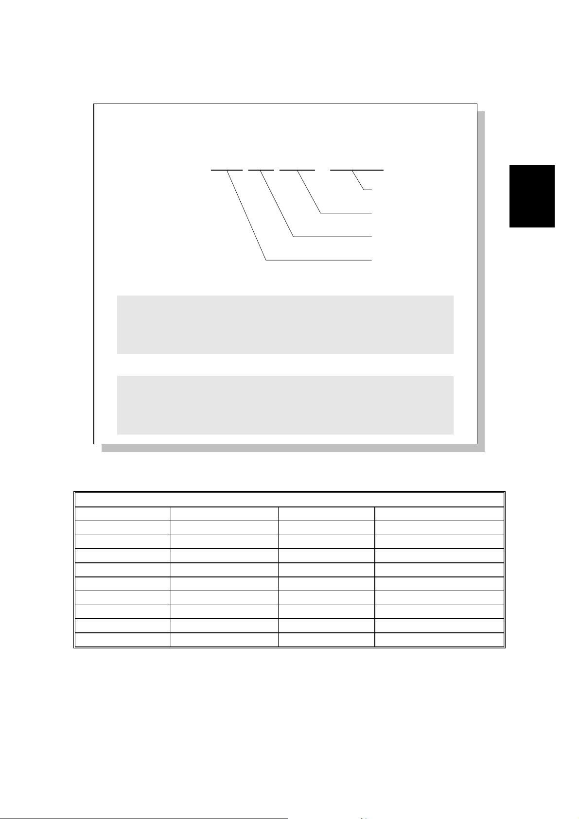
A sample auto service report
* * * Auto Service Report (Date and Time) * * *
Problem Reason of the call - "SC Code" or "PM Call"
S C Latest 10 copier's SC codes
J A M BJ A M 2FEED SIZE005 0000000000
Total print counter
Service Monitor Report Contents
System Parameter List Contents
Paper Size Code
Paper Feed Station
Jam Location
B383D500.WMF
Detailed
Descriptions
Paper Size Code Table
Code Size Code Size
005 A4 sideways 038 8.5 x 11" sideways
014 B5 sideways 160 11 x 17" lengthwise
031 Non-standard 164 8.5 x 14" lengthwise
132 A3 lengthwise 166 8.5 x 11" lengthwise
133 A4 lengthwise 172 5.5 x 8.5" lengthwise
134 A5 lengthwise
141 B4 lengthwise
142 B5 lengthwise
159 Non-standard
2-3
SERVICE CALL CONDITIONS 28 August, 2000
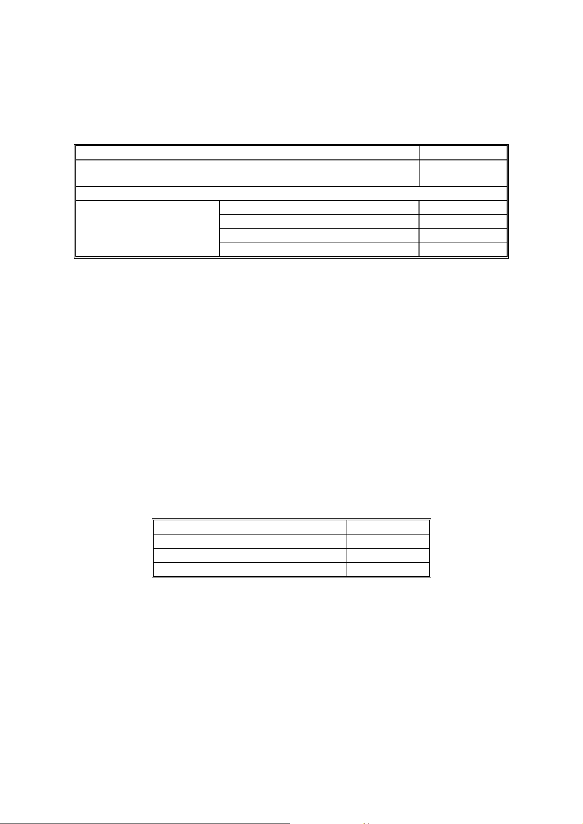
2.1.1 PERIODIC SERVICE CALL
The periodic service call notifies the service station of the machine’s condition. The
call is made at a time interval programmed in the following RAM addresses:
Parameters Address (H)
Call interval: 01 through 15 month(s) (BCD)
00: Periodic Service Call Disabled
Date and time of the next call
Year: last two digits of the year (BCD) 48037A
Month: 01 through 12 (BCD) 48037B
Day: 01 through 31 (BCD) 48037C
Hour: 00 through 23 (BCD) 48037D
480379
To change these settings after programming, change the call interval. The machine
then automatically changes the remaining parameters by referring to the interval
and the current date and time.
2.1.2 PM CALL
If PM alarm is enabled by the base copier’s SP mode and PM call is enabled by
system switch 01, the machine will make an automatic service call when the base
copier’s PM counter reaches the PM interval.
2.1.3 EFFECTIVE TERM OF SERVICE CALLS
If a time limit for the effectiveness of service calls is programmed, the machine
stops making automatic service calls af ter the time limit.
Program the time lim it at the following addresses. This function is disabled when all
of these addresses are 00(H).
Address (H)
Year: last two digits of the year (BCD) 480383
Month: 01 through 12 (BCD) 480384
Day: 01 through 31 (BCD) 480385
2-4

28 August, 2000 SCANNING FEATURES
2.2 SCANNING FEATURES
2.2.1 PARALLEL MEMORY TRANSMISSION
Using basic memory transmission, normally the machine starts dialing after the
document has been completely scanned. Using Parallel Memory Transmission, the
machine starts dialing at the same time the machine starts scanning. If the
document has multiple pages, the machine scans them into memory and sends
them while scanning continues.
NOTE: This function is only usable when sending an original from the ADF.
The following table shows the differe nces between normal memory transmission
and parallel memory transmission.
Normal memory tx Parallel memory tx
File Reserve Report if automatic report printout
is enabled.
If the other terminal is
busy
If transmission failed Tries to resend the
If memory overflows
during scanning
If a document jam
occurred during
scanning
How and when the
scanned message is
erased from memory
Memory threshold to
start scanning into
memory
Meaning of the stamp
mark
Batch numbering (P.
x/x)
Including a sample of
the image on reports
Tries to resend the
message later.
remaining pages later.
Stops scanning and
erases all the scanned
pages from memory, or
sends all the scanned
pages (user's choice).
Stops scanning and
deletes all the scanned
pages from memory.
The complete message is
erased after all the pages
have been sent.
Depends on the setting of
communication switch 0D.
Default settin g - 24kB
Successfully stored. Successfully stored.
Enabled Not available unless the number
Possible Possible
Not printed.
Continues scanning the
document into memory, and
tries to resend it la ter.
Tries to resend the remaining
pages later.
Stops scanning and hangs up
the communication when
memory overflow is detected.
Then erases all the scanned
pages from memory without
notifying the user.
Stops scanning and hangs up
the communication when a
document jam is detected.
Same as memory transmission.
Depends on the setting of
system switch 10.
Default setting - 384 kB
of pages is prog rammed
manually.
Detailed
Descriptions
In the following cases, the machine uses normal memory transmission even if
parallel memory transmission is enabled.
2-5

SCANNING FEATURES 28 August, 2000
• Send later transmission
• Broadcasting
• Transmission of an Auto Document only
• Transfer request transmission
• When Image Rotation before Tx is enabled, and an A4 s id eways or 8.5 x 11"
sideways original is detected
• If the other terminal is busy
• If the external telephone connected to the machine is in use
• When communication switch 0A, bit 0 is set to 1, and the m achine is using
memory transmission when redialing
• When remaining memory space is less than the threshold for parallel
memory transmission (default = 384 kB)
• When the original is located on the exposure glass
When using G4 transmission, parallel memory transmission is normally disab l ed,
because transmission using G4 is much faster than scanning. As a result, G4
transmission using parallel memory transmission takes about twice as long as
normal memory transmission (using an ITU-T #1 test chart).
If the document contains pages with complicated images or it is a photo document
using halftone, parallel memory transmission may be faster than normal memory
transmission. If the user commonly sends this type of fax message, enable parallel
memory transmission fo r G4 transmission by changing system switch 11, bit 7 to 1.
Cross Reference
Parallel memory tx (G3) On/Off - User parameter 07, bit 2
Parallel memory tx (G4) On/Off - System switch 11, bit 7
Memory threshold f or enabling parallel memory tx
- System switch 10, bits 0 to 7
Point of resumption of memory transmission upon redialing
- Communication switch 0A, bit 0
2-6
28 August, 2000 SCANNING FEATURES
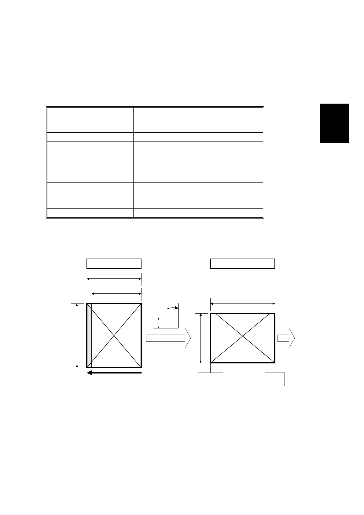
2.2.2 SUB-SCAN LENGTH CORRECTION USING ADF
The ADF informs the FCU of the original length. If the length data is incorrect or the
original is skewed, the machine corrects the sub-scan length to a standard paper
length.
The correction algorit hm is follows.
Before sub-scan length
correction
Under 135mm 128mm (B6 short edge length)
136mm – 157mm 148mm (A5 short edge length)
158mm – 192mm 182mm (B6 long edge length)
193mm – 223mm 210mm (A4 short edge length)
267mm – 287mm 279mm (LT long edge length)
288mm – 307mm 297mm (A4 long edge length)
355mm – 374mm 364mm (B4 long edge length)
410mm – 425mm 420mm (A3 long edge length)
Over 426mm 432mm (DLT long edge length)
NOTE: Depends on the settings of scanner switch 0C bit 6
Length Correction Enabled (Default setting)
223 mm
210 mm or 8.5"
After sub-scan length correction
216mm (LT short edge length)
See the note below the table.
Transmitted ImageOriginal on DF
297 mm or 11"
Detailed
Descriptions
90°
R
R
297 mm or 11"
Scan direction
on exposure glass
When this feature is enable d, in the above example, the gray part of the original is
not scanned. However this allows the machine to rotate the image before
transmission in order to avoid unintentional reduction.
2-7
210 mm or 8.5"
Page
Bottom
Page
Top
B383D501.WMF
SCANNING FEATURES 28 August, 2000
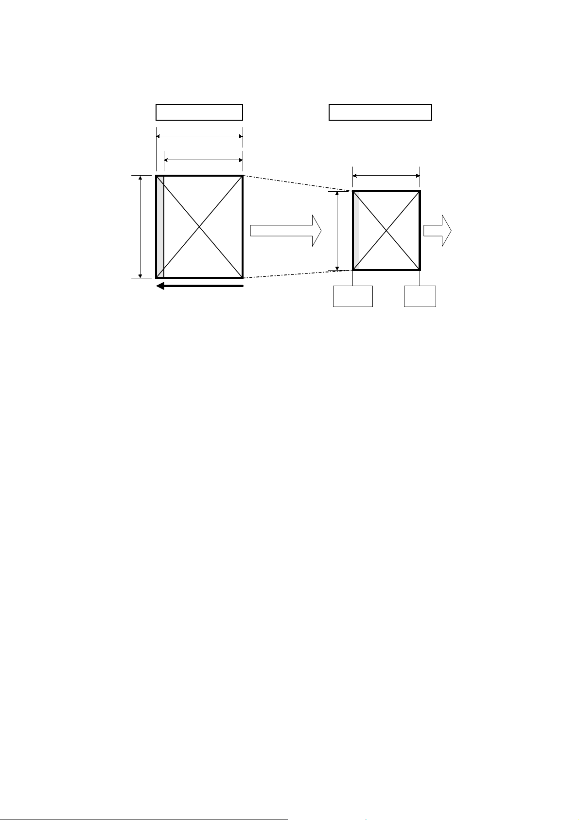
Length Correction Disabled
Transmitted ImageOriginal on DF
223 mm
210 mm or 8.5"
223 mm
Reduced
297 mm or 11"
R
210 mm or 8.5"
R
Scan direction
on exposure glass
In the above example, this feature is disabled. An unintentional reduction may
occur if the receiving machine cannot print on paper with a width of 297mm.
However, with length-correction disabled, the machine sends the entire image.
Cross Reference
• Image rotation before transmission – section 2.2.4.
• Sub-scan length correction on/off – Scanner switch 0C, bit 7
• Default setting is 0. (Sub-scan length correction is enabled)
• Setting A4 or LT size when sub-scan length correction is on.
– Scanner switch 0C bit 6. Default setting is 1. (Recognize as A4 or LT size)
Page
Bottom
Page
Top
B383D502.WMF
2-8
28 August, 2000 SCANNING FEATURES
2.2.3 PAGE SPLIT TRANSMISSION (BOOK TRANSMISSION)
User parameter switch 06,
bit6=1
User parameter switch 06,
bit6=0 (Default)
2
1
1
2
B383D503.WMF
This function allows a B4, A4/8.5 x 11", or A3/11 x 17" size book original to be sent
as two separate pages.
Detailed
Descriptions
When this function is selected, the machine scans the original twice and transmits
the pages in the same sequence they were scanned.
With the default setting, the left page is sent first, then the right page is sent. If the
setting is changed, the order is reversed.
Cross Reference
• Scanning start page – User parameter switch 06, bit6
• Default setting is 0. (Start scan from the left)
NOTE: 1) Memory transmission is used whenever this function is selected.
2) This function is only possible when sending a book original f rom the
exposure glass.
3) If this function is used for an A3 or 11 x 17" original, the pages may be
transmitted in a lengthwise direction, depending on the setting of "Image
Rotation before Transmission" (see the next page).
2-9
SCANNING FEATURES 28 August, 2000
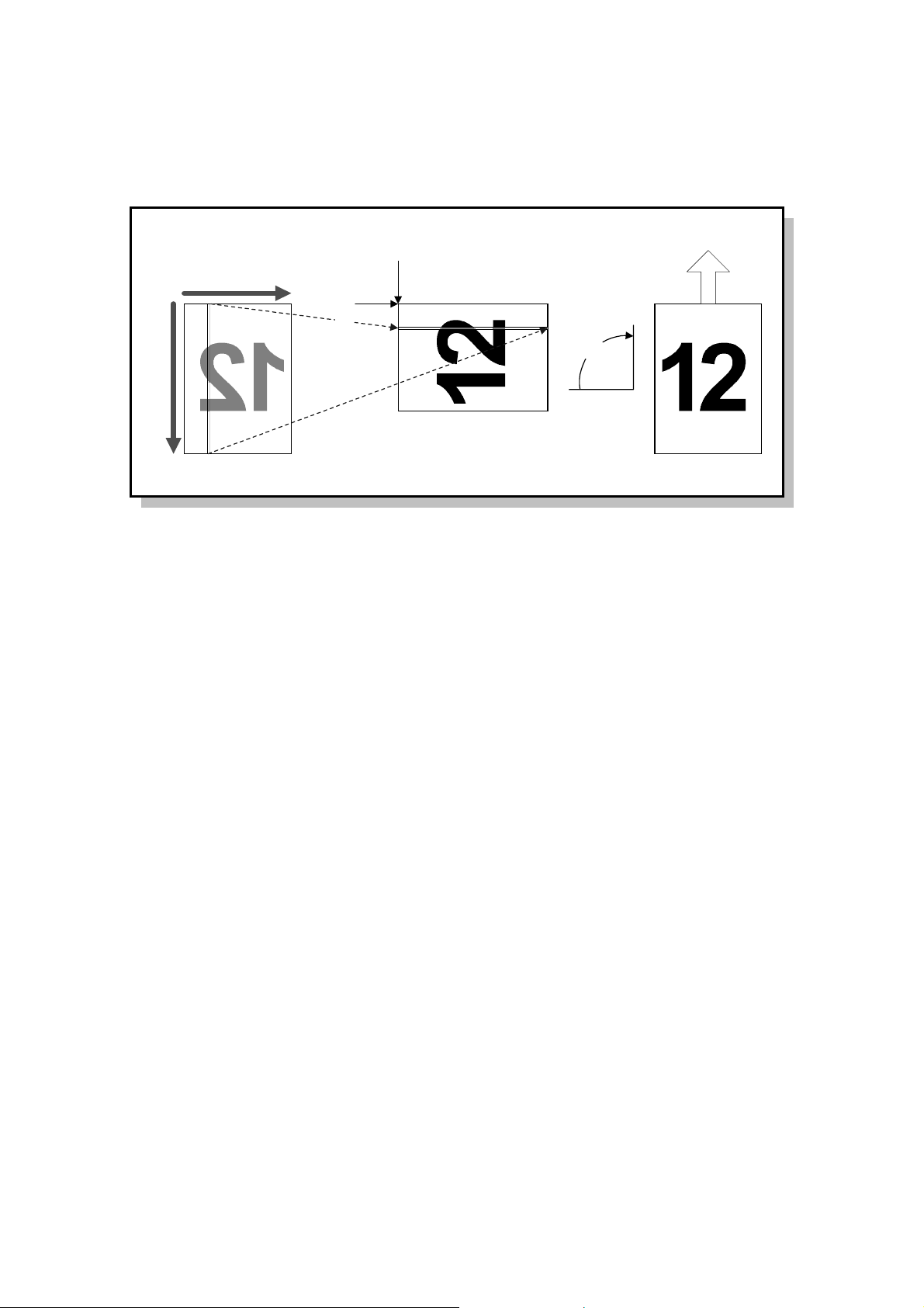
2.2.4 IMAGE ROTATION BEFORE TRANSMISSION
1st Pixel
1st Line
90°
Scanned ImageOriginal Transmitted Image
B383D504.WMF
(< 210mm/8.5")
Main Scan
(297mm/11")
Sub Scan
A4 or 8.5 x 11” sideways
This function avoids the unintentional reduction of an A4 or 8.5 x 11” sideways
original. When the machine detects a sideways A4 or 8.5 x 11" original in the ADF
or on the exposure glass, the fax unit rotates the scanned image clockwise by 90
degrees before transmission, as shown above.
A5 or HLT lengthwise
This function avoids a blank space in the main scan direction. When the machine
detects an A5 or HLT original placed lengthwise in the ADF or on the exposure
glass, the fax unit rotates the scanned image clockwise by 90 degrees before
transmission, as shown above.
NOTE: 1) Even if Parallel Memory Transmission is enabled, the machine uses
normal memory transmission to send an A4 or 8.5 x 11" sideways
original.
2) If the machine carries out this function while printing, the machine stops
printing until scanning is completed.
3) The machine determines if it will rotate the image after the paper size is
determined.
4) This feature is not performed during parallel memory transmission.
5) In Book mode, the machine determines image rotation for each page
scanned.
In ADF mode, the machine determines image rotation for the first page.
If it is rotated, the machine will check each page. If the first page need
not be rotated, the machine will not check the rest of the pages.
2-10

28 August, 2000 SCANNING FEATURES
Cross Reference
• Image rotation before Tx A3 or 11” width original on/off
- Scanner switch 0F, bit 0 (Default setting is enabled)
• Image rotation before Tx A5 or HLT width original on/off
- Scanner switch 0F, bit 2 (Default setting is disabled)
• Small size original detection
- Scanner switch 0C, bits 1 and 2
(Default setting is “Depends on the setting of the base copier.”)
Detailed
Descriptions
2-11

PRINTING FEATURES 28 August, 2000
2.3 PRINTING FEATURES
2.3.1 PAPER SIZE SELECTION
This section explains how the FCU selects the appropriate paper size for printing a
received fax image. Refer to the ’Paper Size Selection Priorities’ tables at the end
of this section for how the appropriate paper size is actually selected.
WIDTH PRIORITY AND LENGTH PRIORITY
When ’W idth Priority’ is selected, a paper si ze of the same width as the received
fax image has a higher priority. The fax image may be printed on several pages.
When ’Length Priority’ is selected, a paper size that has enough length to print the
received fax image has higher priority. The fax image is printed on one sheet of
paper, but the printed fax may have wide margins on the left and right.
Cross Reference
• Paper selection priority - Printer switch 0E, bit 0 (Default: Width)
IMAGE ROTATION BEFORE PRINTING
If the machine has the same size paper as the received fax image size, but in
sideways orientation, the fax unit rotates the image by 90 degrees clockwise, and
prints it sideways.
This feature is only possible when the received fax image is one of the following
sizes: A4 lengthwise, 8.5 x 11" lengthwise, B5 lengthwise
NOTE: This function can not be disabled.
2-12
28 August, 2000 PRINTING FEATURES
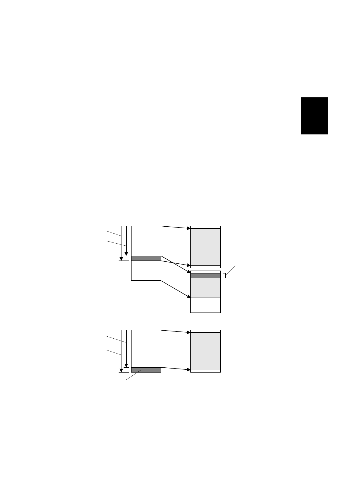
SUB-SCAN REDUCTION AND PAGE SEPARATION
Sub-scan Reduction Disabled
When Sub-scan Reduction is disabled, the received fax image is printed
unreduced.
If the image is longer than the paper length + 6 mm, the image is separated onto
two pages (see the top drawing below).
If the image is shorter than the paper length + 6 mm but longer than the paper
length - 4 mm, the part of the image after paper length - 4 mm will be lost (see the
bottom drawing below).
NOTE: The page separation threshold is adjustable between 0 and 15 mm (the
default is paper length + 6 mm). Refer to Printer Switch 03, bits 4 to 7 for
more details.
The 2 mm gaps at the leading and trailing edges depend on the leading
and trailing edge margin settings.
The 10 mm image duplication can be adj ust ed or disabled.
Detailed
Descriptions
Paper length - 4 mm
Paper length - 14 mm
Paper length - 4 mm
Within
Paper length +6 mm
Not printed
Received Image Printed Image
Duplicated (10 mm)
Received Image Printed Image
2-13
B383D505.WMF
PRINTING FEATURES 28 August, 2000
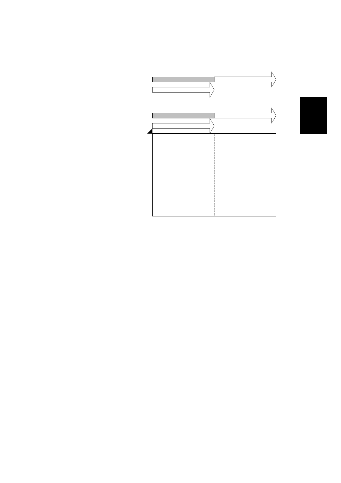
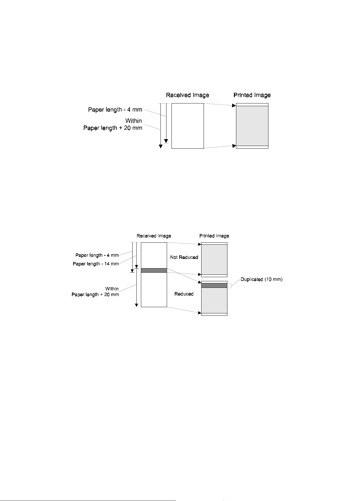
Sub-scan Reduction Enabled
When Sub-s can Reduction is enabled, the received fax image is reduced in the
page memory to fit on the selected paper, if the received image length is between
[paper length - 4 mm] and [paper length + 20 mm]. See the drawing below.
B383D506.WMF
NOTE: The upper limit (page length + 20 mm) is adjustable between 0 and 155
mm. Refer to Printer Switch 04, bits 0 to 4 for more details.
If the FCU detects that the image must be separated into more than one page after
reduction, what happens to the data depends on the Reduction Rate Equalization
setting (Printer Switch 0E, bit 7).
- Reduction Rate Equalization Off (Example Diagram: Two-page Printout) -
B383D509.WMF
1. The data up to [page length - 4 mm] will be printed on page 1, without
reduction.
2. The last 10 mm of this data will be repeated at the top of the next page (this
length can be can be adjusted or repetition can be switched off).
3. The remaining data will be printed on page 2, with reduction, if it is within
[paper length + 20 mm].
4. If it is longer than this, page separation is done again. Data up to [page length 4 mm] will be printed on page 2, without reduction.
5. The process for page 3 and subsequent pages will repeat from step 2.
2-14

28 August, 2000 PRINTING FEATURES
- Reduction Rate Equalization On (Example Diagram: Two-page Printout) -
B383D508.WMF
1. The machine determines how many pages will be needed to print the message,
taking the following into account:
The final page (n) is such that the received image length is within (paper length
x n) + 20 mm
The data must be reduced to fit on pages of length (paper length - 4 mm), with
an equal reduction rate for each page
The last 10 mm of the previous page will be repeated a t the top of the next
page (this length can be adjusted or repetition can be disabled).
2. The machine prints all the pages, at the same reduction rate.
If the customer does not want to receive a fax message on separate pages, page
separation can be disabled. However, once it has been disabled, the machine does
not print the received fax message until a paper size which can hold the received
fax image on one page is set in a cassette. Keep page separation enabled if the
customer expects to receive fax messages longer than the installed paper.
Cross Reference
Parameter Switch Default Setting
Reduction in sub-scan direction
on/off
Equalizing reduction rate among
separated pages
Page separation threshold when
reduction is disabled
Page separation threshold when
reduction is enabled
Page separation on/off Printer Switch 0E, bit 2 Enabled
Page separation mark on/off Printer Switch 00, bit 0 Enabled
Image duplication with page
separation, on/off
Length of the repeated image on
the next page
Printer Switch 03, bit 0 Enabled
(except Germany)
Printer Switch 0E, bit 7 Enabled
Printer Switch 03, bits 4-7 6 mm
Printer Switch 04, bits 0-4 20 mm
Printer Switch 00, bit 1 Enabled
Printer Switch 04, bits 5-6 10 mm
Detailed
Descriptions
2-15
PRINTING FEATURES 28 August, 2000
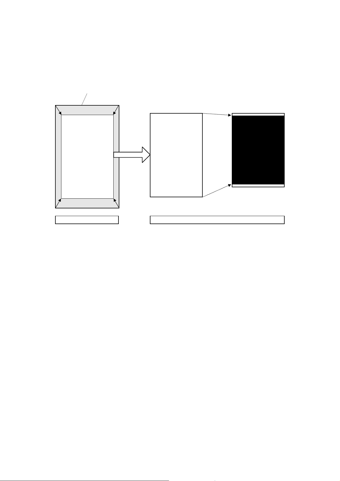
PAGE REDUCTION
This function allows a received fax image to be printed on paper with less width
than the fax image.
Received Image
Printed Image
Reduced Image
Page Reduction Sub-Scan Reduction
Reduced Image
B383D507.WMF
First, the received im age is reduced by a fixed reduction rate in the main and subscan directions. The available reduction rates are as follows:
• 84% - A3 to B4 reduction
• 82% - B4 to A4 lengthwise reduction
Then, the reduced image is further reduced (if necessary) in the sub-scan direction
so that it can be printed on one page. However, if the FCU detects that the image
does not fit on one page after sub-scan reduction, the FCU cancels the page
reduction, but uses normal sub-scan reduction on the received fa x image.
NOTE: 1) Sub-scan reduction is automatically enabled when Page Reduction is
enabled.
2) A3 to A4 reduction is not available.
Cross Reference
• Page reduction on/off - User parameter 10 (0A), bit 3 (Default: Disabled)
2-16

28 August, 2000 PRINTING FEATURES
Examples
1. When printing a B4 size fax image on 8.5" x 11" lengthwise paper
• Fax image size: 256 x 364 mm (10.7 x 14.3")
• Paper size: 216 x 279 mm (8.5 x 11")
• Reduction rate used: 82%
• Page separat ion threshol d: 20 mm
The received image is printed on one 8.5 x 11" sheet, because the image length
after page reduction (364 mm x 82% = 298.5 mm) is shorter than the paper length
(279 mm) plus 20 mm.
2. When printing a non-standard size (256 x 400 mm) fax image on 8.5 x 11"
lengthwise paper
• Fax image size: 256 x 400 mm (10.7 x 15.7")
• Paper size: 216 x 279 mm (8.5 x 11")
• Reduction rate used: 82%
• Page separat ion threshol d: 20 mm
The received fax im age is printed on two 8.5 x 11" sheets after page separation
and image rotation, because the image length after page reduction (400 mm x 82%
= 328 mm) is longer than the paper length (279 mm) plus 20 mm.
Detailed
Descriptions
Refer to the “Paper Size Selection Priorities” table later in this chapter.
TWO IN ONE
This function allows two small pages to be printed on one sheet of paper. However,
this function only works when the machine does not have the following size of
paper in the cassette.
• The same size of paper as the received image
• The paper which has the same width and sufficient length
Cross Reference
• Two in one on/off - User parameter 10 (0A), bit 1 (Default: Disabled)
2-17
PRINTING FEATURES 28 August, 2000
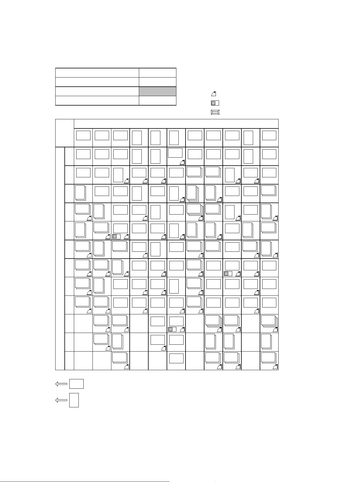
2.3.2 PAPER SIZE SELECTION PRIORITIES
Page Reduction
Reduction in Sub-scan Direction
Page Separation Threshold
Width or Length Priority Width
Disabled
Disabled
Received Image Size
A3 B4 A4
A3 B4 A4
1
11x17"
2
A4
3
A4
4
5
11x17" F/F4
B5
8.5x11"
A3
B5
A4
8.5x14"
A4 B5 A5
A4 B5
A4 B5
8.5x11"
8.5x11"
A3
A3
B4
A4
A4
A5
8.5x11"
8.5x11"
A4
A4
: Image Rotation
: Half of the page is blank
: Page Reduction
11x17" 8.5x11"8.5x14"
11x17" 8.5x14" 8.5x11"
A3 A4
8.5x11"
A4 A4
8.5x11"
A4
8.5x11"
A4
A4
F/F4
8.5x11"
F/F4
8.5x11"
F/F4
8.5x11"
8.5x11" 8.5x14"
A4
A3
11x17"
A4
A4
8.5x11"
8.5x11"
6
7
8
Paper Select Priorities
8.5x14"
9
10
11
12
A4
F/F4
B4
8.5x11"
8.5x14"
Lengthwise
Sideways
A4
8.5x11"
F/F4
8.5x11"
B4
11x17"
A5
B5
B5
8.5x11"
F/F4
11x17"
B4
8.5x14"
8.5x11"
8.5x11"
F/F4
A3 B5
11x17"
8.5x14"
F/F4
8.5x14"
B5
A3
B4
11x17"
8.5x11" F/F4
F/F4
B4
8.5x14"
B4 A3 B4
A3 B4 B4 A3
11x17" 11x17"
A5 A5A5
B5 B5 B5
B5 B5 B5
8.5x14"
A4
8.5x11"
F/F4
8.5x14" 11x17"
2-18
A693D510.WMF
 Loading...