

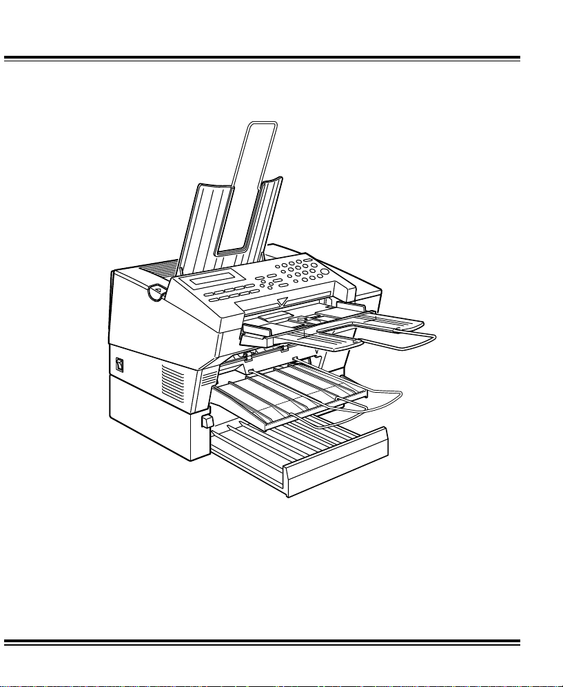
FAX1700L
RICOH
Read the safety instructions on page i to iv
Operator’s Manual

Optional equipment
PAPER FEED UNIT TYPE 70
A paper feed unit can be add ed to th e ba se mach ine.
F AX EXPANSION CARD TYPE 10
A 1-Mbyte memory card can be added.
F AX EXPANSION CARD TYPE 20
A 2-Mbyte memory card can be added.

Caution
Use of control or adjustments or performance of procedures
other than those specified herein may result in hazardous
radiation exposu re
Shielded int ercon nect c ables must be employed with this
equipment to ensure compliance with the pertinent RF
emission limits governing th is device .
In accordance with ISO 7001, this machine uses the following
symbols for the main switch:
s means POWER ON
t means POWER OFF
WARNING
This symbo l is i ntended to alert the user to the presence of
important operating and maintenance (servicing) instructions
in the literature accom pa nying the machine.
Operator Safety
This machine is classified as class 1 lase r d evice a ccor din g to
IEC825. The Facsimile contains a 5-milliwatt, 770-810
nanometer wavele ng th , AI Ga As laser diode.
Direct (or i ndirect refl ected eye contact with the laser beam
may cause serious eye damage. Safety precautions and
interlock mechanisms have been designed to prevent any
possible laser beam exposu re to th e op er at or.
NOTICE TO USERS (New Zealand)
Equipment connected to the interface port shall be certified to
meet the requirements of Reg. 18 of the New Zealand wiring
Regulations 1976 .
Telepermitted equipment only may be c onnected to the
interface port.
The operation of this equipment on the same line as
telephones or other equipment with audible warning devices
or automatic ring detectors will give rise to bell tinkle or noise
and may cause false tripping of th e rin g de te cto r. Should such
problems occur, the user is not to contact Telecom Faults
Service.
Immediately disc onnect t he equipment s hould it ever suffer
physical damage which results in the internal parts becoming
accessible in normal use. Arrange for its dispos al or have it
repaired before it is reconnected.
Should it necessary to move the equipment, it is necessary to
disconnect the Telecom network connection before
disconnecting the Power lead or any separate earth lead.
Similarly, when reconnecting the equipment it is necessary to
connect the p ower lead or earth lead before connecting the
telecom Network.
Not all standard telephones will respond to incoming ringing
when connected to the exte nsio n socke t.

SAFETY
Important Safety Instructions
All safety messages in the main text of this manual are labeled WARNING or
CAUTION. These mean the following:
WARNING: Important information to alert you to a situation that might cause
serious injury and damage to your property if instructions are not
followed properly.
CAUTION: Importa nt i nf or m atio n th at t el ls ho w to p reve nt d am ag e to yo ur
equipment or ho w to avoi d a situa tion that mi ght cau se mi nor inj ury.
In addition to the warnings and cautions included in the text of this manual,
please read and observe the following safety instructions.
1 Read all of these instructions.
2 Save these instructions for later use.
3 Follow all warnings and cautions marked on the product.
4 Unplug this product from the wall outlet before cleaning. Do not use
liquid cleaners or aerosol cleaners. Use a damp cloth for cleaning.
5. Do not use this product near water.
6. Do not place this product on an unstable cart, stand, or table. The product
may fall, causing serio us dama ge to the pr oduc t or inju ring th e user.
7. Slots and openings in the cabinet and the back or bottom are provided
for ventilation; to ensure reliable operation of the product and to protect
it from overheating, these openings must not be blocked or covered.
The openings should never be blocked by placing the product on a bed,
sofa, rug, or other similar surface. This product should not be placed in a
built-in installation unless proper ventilation is provided.
8. This product should be operated from the type of power source
indicated on the marking label. If you are not sure of the type of power
available, consult an authorized sales person or your local power
company.
9. This product is equipped with a 3-wire grounding type plug, a plug having a
third (groundi ng) pi n. Th is plug will on ly fi t into a g rou ndin g-type powe r
outlet. Thi s i s a sa fety fe at ur e . If yo u ar e u na bl e to i nse r t th e pl u g i nt o t he
outlet, conta ct you r e le ctrician to replace yo ur ob sol et e ou tl et . Do n ot d efea t
the purpose of t he gr ou nd ing typ e pl ug . (T hi s d oes not a pp ly in co untr i es in
which the 2-wire, non-grounded type of plug is used.)
i

SAFETY When to Call Your Service Representative
10. Do not allow anything to rest on the power cord. Do not locate this
product where persons will walk on the cord.
11. If an extension cord is used with this product, make sure that the total of
the ampere ratings on the products plugged into the extension cord
does not exceed the extension cord ampere rating. Also, make sure that
the total of all products plugged into the wall outlet does not exceed 15
amperes.
12. Never push objects of any kind into this product through cabinet slots as
they may touch dangerous voltage points or short out parts that could
result in a risk of fire or electric shock. Never spill liquid of any kind on
the product.
13. Do not attempt to service this product yourself, as opening or removing
covers may expose you to dangerous voltage points or other risks.
Refer all servicing to qualified service personnel.
When to Call Your Service Representative
WARNING: Do not attempt any maintenance or troubleshooting other than
that mentioned in this manual. This machine contains a laser
beam generator and direct exposure to laser beams can cause
permanent eye damage.
Unplug this product from the wall outlet and refer servicing to qualified service
personnel under the following conditions:
A. When the power cord or plug is damaged or frayed.
B. If liquid has been spilled into the product.
C. If the product has been exposed to rain or water.
D. If the pr oduct does not operate normally when the operating instructions
are followed. Adjust only those controls that are covered by the
operating instructions since improper adjustment of other controls may
result in damage and will often require extensive work by a qualified
technician to restore the product to normal operation.
E. If the product has been dropped or the cabinet has been damaged.
F. If the product exhibits a distinct change in performance, indicating a
need for service.
ii

Power and Grounding SAFETY
Power and Grounding
Power Supply
1. Power requirements: 220-240 V, 50Hz
2. Insert the power plug securely into the wall socket.
3. Make sure that the wall outlet is near the machine and readily
accessible.
4. Do not connect other equipment to the same socket.
5. Do not step on or set anything on the power cord.
6. Do not connect other equipment to the same extension cord.
7. Be sure that the power cord is not in a position where it would trip
someone.
8. The wall outlet must be easily accessible.
Grounding
Ground the mac hine and the l ightning protection circuit in accordance with
regulations. Do not ground to gas or water pipes, or to a telephone ground
plug. Proper grounding is to the ground terminal of the power outlet. Be sure
that the ground terminal of the power outlet is properly grounded.
The lightning p rotection ci rcuit for the ma chine requires the mac hine to be
properly grou nded. If prop er grounding i s provided, about 90% of lightning
damage can be prevented. For safety, be sure to connect the machine to a
three-prong grounded outlet.
Cold Weather Power-up
Avoid raising the room temperature abruptly when it is below 14°C, or
condensation may form inside the machine.
1. Raise the room temperature to 10°C at less than 20°C per hour.
2. Wait for 30 to 60 minutes.
3. Turn the power on.
4. Do not use the machine near a humidifier.
iii
SAFETY Thunderstorms
Thunderstorms
With proper grounding, about 90% of lightning damage can be prevented.
However, if possible, during severe electric storms turn the power switch off
and disconnect the power cord and telephone line cord.
GENERAL
1. Since some parts of the machine are supplied with high voltage, make
sure that you do not attempt any repairs or attempt to access any part of
the machine except those described in this manual.
2. Do not make modifications or replacements other than those mentioned
in this manual.
3. When not using the machine for a long period, disconnect the power
cord.
Ozone
The machine generates ozone during operation. Normally, the ozone level is
safe for operators. However, during a long copy run or while printing a long
message, ozone odor may appear; in such a case, ventilate the room.
Symbols & Conventions Used In This Manual
Documents: A document is anything you put on the feed table of your ma-
chine whether your are faxing it or copying it.
Prints: A print is anything that comes out of the machine: a fax mes-
sage you received or a copy you made.
Procedures: Procedures are described step by step. Perform them in or-
der. When you see an LCD display, it always shows what
comes
trations accompanying steps help you find the right key or
handle, or show you how to perform the step.
This is a step in a procedure.
1
iv
after performing the step it accompanies. Other illus-
THIS CORRESPONDS TO
THE LCD DISPLAY.
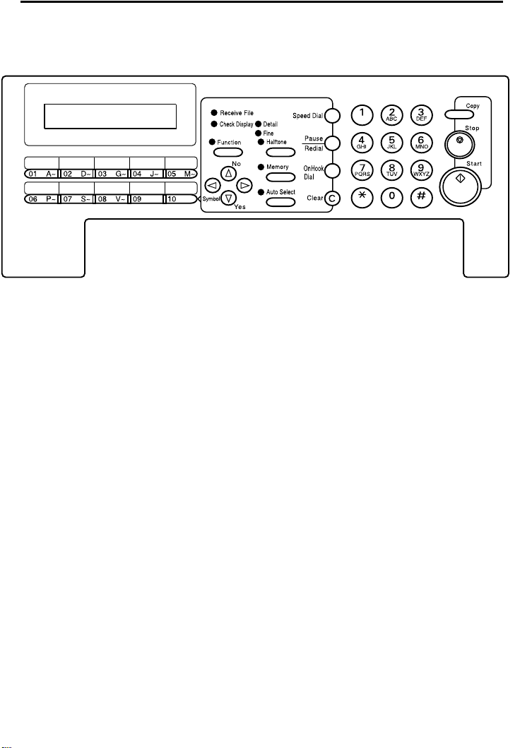
Operation panel
Machine Layout
1- The Receive File indicator lights when a fax
message is stored in memory (see page 14).
2- The Check Display indicator lights to tell you to
read the display.
3- Press the Auto Select key to use Auto Receive
Mode. The indicator lights when you are in this
mode.
4- The resolution/Halftone is indicated by these three
indicators and can be changed by the
resolution/Halftone button.
5- When the Memory indicator is on, then memory
transmission is in effect, if it is off, immediate
transmission is in effect. Switch between the two
with the Memory button.
6- There are ten Quick Dial keys. Use them to store
individual numbers (see page 21) or groups (see
page 23 ). Use the keys to enter characters (see
page 71). Use Quick Dial 09 as a dial option key .
Use Quick Dial 10 as a Group key (see page 25).
7- The Liquid Crystal Display guides you through tasks
and informs you of the state of the machine.
Messages appear here. The LCD consists of two
20-character lines.
8- Use the arrow buttons to navigate through functions,
to accept or reject settings, or to set functio n options.
9- Press the Function key and enter a two digit code
to access functions 11 to 51. (For functions 61 to 94,
enter 6, the access code on page 64 and the
function number.)
10- Press the Speed Dial key and enter a two digit code
(between 00 & 49) to dial or store individual
numbers (see page 21).
11- The Pause/Redial key inserts a pause when you
are dialing or storing a fax number. Or, press the key
to redial the last number dialed. (The redial feature
doesn’t work once you’ve started dialing a new
number.)
12- Press the On Hook Dial key to dial a phone call
from the keypad without having to lift the phone or
handset off the hook (phone or handset option
needed).
13- Press the Clear key to erase the last character or
digit entered, or use the left and right arrow keys to
move the cursor and then press Clear to erase
whatever is at the cursor.
14- Press the Stop key to stop a tran smission or a
document scanning, to stop a reception or to stop a
long copy run. The machine will finish printing out
the sheet being printed and then stop.
15- Press the Start key to start all tasks.
16- Use the numeric keypad (sometimes called the 10
keys) to dial fax numbers, to enter the numbers of
copies, etc.
1
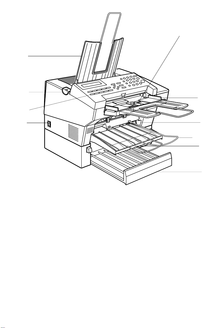
Part Names
4
5
3
2
1
1- The main switch turns your machine on and off.
2- 10 Quick Dial keys store telephone numbers.
3 The cover release button
4- Incoming faxes and copies are sent to the copy
tray.
5- The automatic document feeder (ADF) holds up
to 30 sheets which are fed one at a time. Place your
original documents here.
6- Match the document guide to the size of your
original documents.
7- Scanned documents are stacked on the Document
Tray.
8- The main paper tray holds copy paper.
6
9
7
8
10
9- When loading paper, match the paper guide to the
paper size.
10- The optional paper feed unit holds more paper.
2

FAXING
If you have not yet installed your fax machine, do so now. See Installation, on
page 75.
This section covers what you’ll most often need to do:
Recommended Types of Document ................................................................ 4
Memory Tran smis sion and Im mediat e Transmission................ .. .... .. .... .. .... .. ...6
Receiving Calls & Fax Messages(Faxes/Phone Calls).................................... 11
Printing a Message Received & Stored
(Substitute Rec ep tion) ......... ...................................... ....................................... 14
Faxing a Page With Very Fine Detail ................................................................ 15
Optional Fea ture for Tran smis si on..... . . .. ............ ............ ............ .. . . .. ............ ..... 16
Redialing.................. ...................................... .................................................. .19
Storing & Editing Fa x Numbe rs (Fu nc ti on s 31 & 32)......... .. .......................... ... 21
Storing & Editing a Grou p of Fax Numb ers (Fun ct io n 33 )............. ................... 23
Chain Dialing........... ............................ ............................ ............................ ...... 27
Erasing a Stored Messa ge Before It Is Sent
(Functions 21 & 22)........................................................................................... 28
Printing a Stored Message (Function 51).......... ............ ............ ............ .. .........29
Polling Reception (Function 11)........................................................................ 30
Talking Before Sending a Fax(On Hoo k Dial)................................................... 31
Sendin g a Fax using the Handset ................................ .................................... 31
A Few Hints...
Press Clear to erase the last letter or digit that you entered.
Press No to erase the entire name or number and start again.
To enter characters and labels, turn to page 71.
3
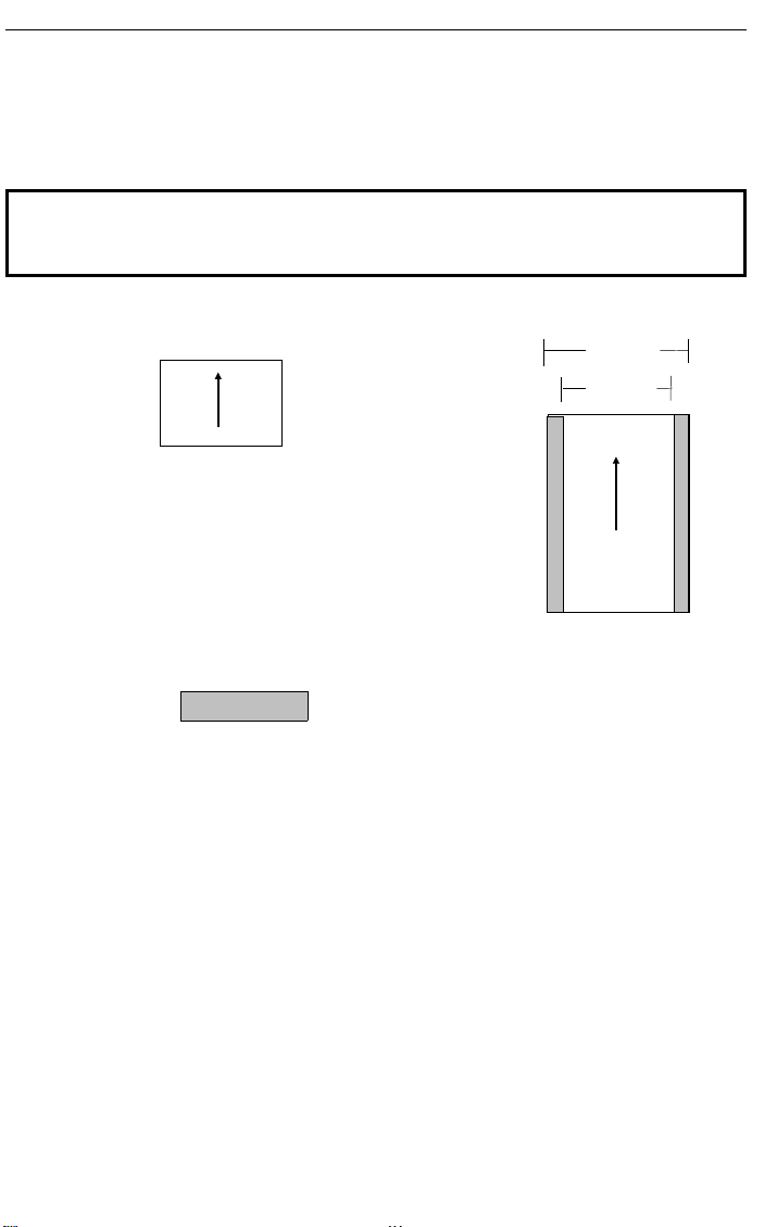
216mm
Scanning direction
Maximum si ze
FAXING Recommended Types of Document
Recommended Types of Document
Before you send your document, make sure that it meets the following
requirements.
CAUTION: Documents that do not meet these requirements can cause your
machine to jam or may cause some components of the machine to become
damaged or dirty.
Minimum si ze
105mm
Scanning direction
148mm
208mm
600mm
*The part shaded will not be scanned, because it is outside the
maximum scanning width range.
Correct Size for the Auto Document Feeder
2
Thickness: 0.05 to 0.2mm (50 to 90g/m
paper)
Length and Width: See the above diagram.
If the page is too short, put it inside a document carrier or enlarge it with a
copier.
If the page is too long, divide it into two or more sheets.
Clearly Written
Small faint characters may not be transmitted clearly.
Uniform Page Size
Do not use different sizes of document in the same transmission.
4
Recommended Types of Document FAXING
Page Condition
Do not place damaged pages in the automatic document feeder.
❐ If your pages are curled or dog eared, flatten them.
❐ If your pages are stuck together, shuffle the stack.
❐ If your pages are folded, torn, or patched together, make copies.
❐ If your pages have binding hiles, trim the edges or make copies.
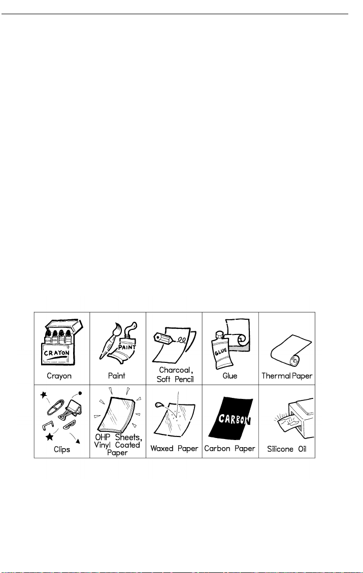
Originals that contain the f ollowing mate rials should no t be placed in the
document feeder.
Note: Copies made with a copier that uses silicone oil may cause a misfeed.
To avoid this, do not scan such copies until five or ten minutes after
copying.
5

FAXING Memory Transmission and Immediate Transmission
Memory Transmission and Immediate Transmission
There are two ways to send a fax message.
❐ Immediate T ran smis sion
❐ Memory T ransmis sion
Immediate Transmission (Memory indicator not lit)
Immediate Transmission is convenient when:
❐ Y ou wish to send a message immediately
❐ You wish to quickly check whether you have successfully connected with the
other party ’s fax machine.
❐ Your machine’s memory is getting full
The machine dials immediately after you press Start (or at the specified later
time, if you used a time- delay feature like Send Later). The message is
scanned and transmitted page by page without being stored in memory.
Memory Transmission (Memory indicator lit)
Memory Transmission is convenient because:
❐ Fax messages can be scanne d much more qui ck ly (you can tak e yo ur
document away from th e fax machine without wait in g to o lo ng ).
❐ While your fax message is being sent, another user can operate the machine
(people will not have to wait by the fax machine too long).
❐ You can send the same message to more than one place with the same
operation.
After you press Start, the machine doesn’t dial until all the pages of your fax
message have been stored in the memory.
6
Memory Transmission and Immediate Transmission FAXING
Memory Transmission
Caution: If your document gets stuck while it is being processed, press the
Stop key, and turn to page 55 for instructions on how to safely remove the original.
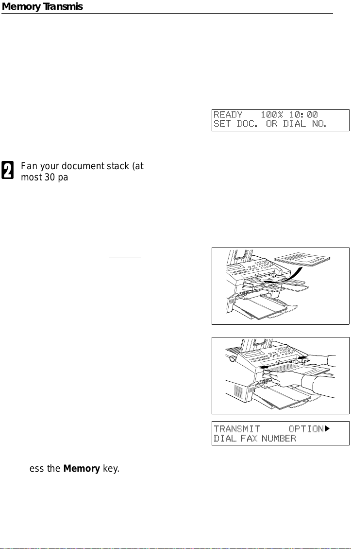
Make sure that the machine is in
1
standby mode for faxing. The display should look like this:
Fan your document stack (at
2
most 30 pages: 80g/m
sure all pages are loose, then
square it.
All pages in your document must
be one-sided and be of the same
size.
Insert the document face up in
3
the feeder and adjust the guides
to fit the width of the document.
Note: You can dial before you set
the document. Place the document after you dial the number
and go to step 7.
2
READY 100% 10:00
SET DOC. OR DIAL NO.
) to make
The display will look like this:
4
If the memory indicator is not lit,
5
press the Memory key.
TRANSMIT OPTION
DIAL FAX NUMBER
k
7
FAXING Memory Transmission and Immediate Transmission
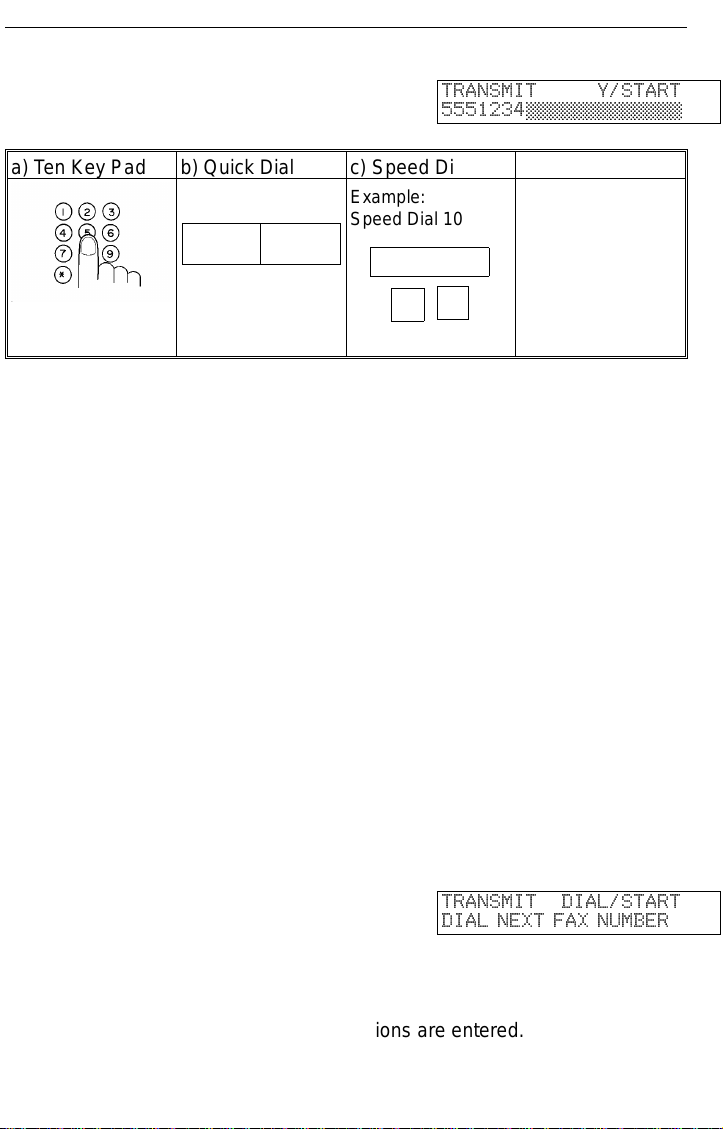
Dial the number in one of the fol-
6
lowing ways.
a) Ten Key Pad b) Quick Dial c) Speed Dial d) Group
Example:
Speed Dial 10
06 07
If you install the handset, you can sent the message manually. Pick up
the handset and dial.
If you want to erase a digit of the phone number, press the Clear key.
If you want to erase the entire number, press the No key.
*: In this example Group Dial is programmed in Quick Dial 08.
**: In this exampl e Quick Dial key 10 is program med as the Group key, and
Group dial number 1 is programmed.
Programming Quick Dial: see page 21.
Programming Speed Dial: see page 21.
Programming Group Dial: see page 23.
Programming Group key: see page 25.
Note: The ma ximum destinations you can dial using the ten key pad is 49.
However, this limitation is also subject to memory capacity.
If you enter the wrong number,
press No or Clear and enter
again.
Press Clear to delete one digit.
Press No to delete the whole
number.
Speed Dial
1 0
TRANSMIT Y/START
5551234©©©©©©©©©©©©©
Example:
Method 1 *
Quick Dial key 08.
Method 2 **
Quick Dial key 10
and 1 on the ten
key pad.
Press Yes to enter another num-
7
ber.
If you have only one destination,
press Start.
Repeat steps 6 and 7 until all destinations are entered.
8
8
TRANSMIT DIAL/START
DIAL NEXT FAX NUMBER
Memory Transmission and Immediate Transmission FAXING
The machine stores your message and dials the first number (or, if you
selected Send Later, it will return to standby mode and the fax message
will be sent at the time that you selected). Send later: see page 16 .
Press the Start key and wait. The
9
machine will dial the destination’s
5551234
SET DOC. OR DIAL NO.
number.
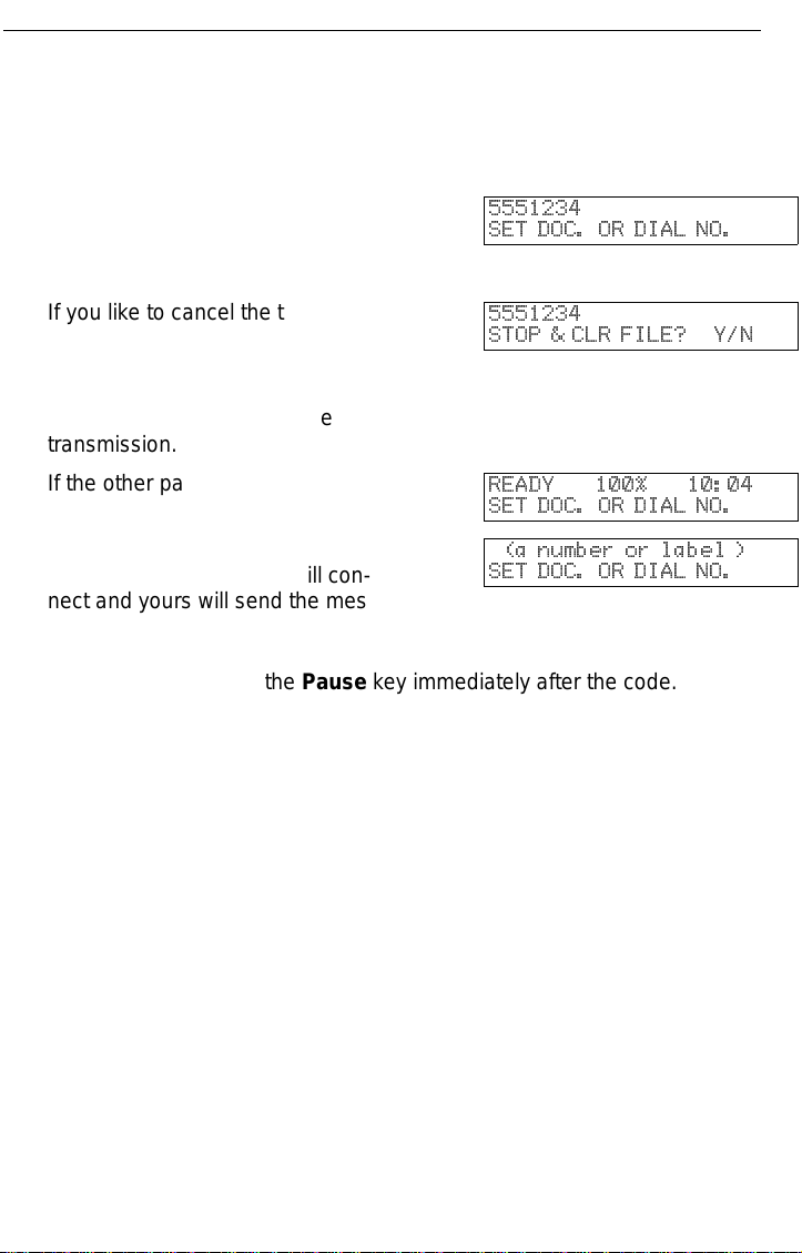
If you like to cancel the transmis-
sion, press the Stop key during
5551234
STOP & CLR FILE? Y/N
communication.
Then press Yes to cancel the
transmission.
If the other party’s line is busy,
your machine will dial again.
If the other party’s fax machine
answers, both machines will con-
READY 100% 10:04
SET DOC. OR DIAL NO.
(a number or label )
SET DOC. OR DIAL NO.
nect and yours will send the message.
Tip: If your line goes through a local switchboard (a PBX) remember to dial
the exit code. Press the Pause key immediately after the code. If the
number includes a country code, press the Pause key after the country code, then dial the rest of the number.
9
FAXING Memory Transmission and Immediate Transmission
Immediate Transmission
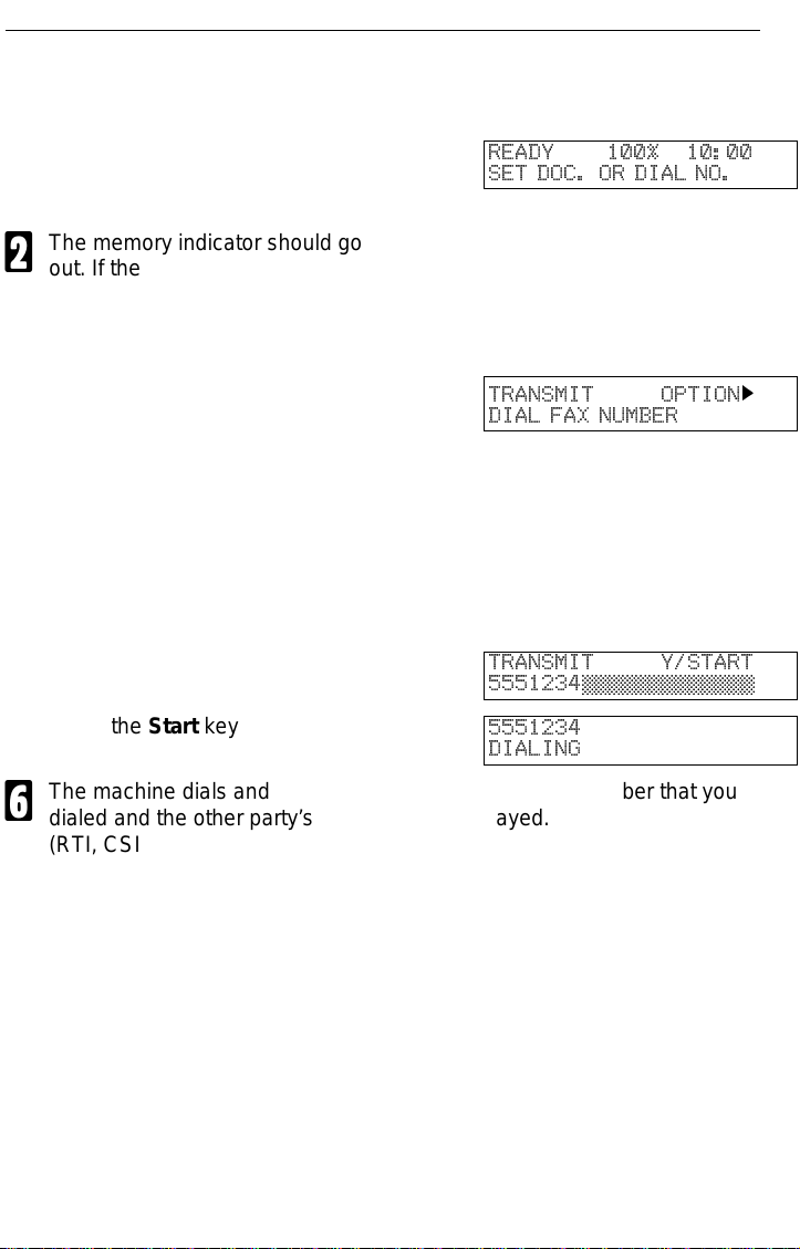
Make sure that the machine is in
1
standby mode. The display
should look like this:
The memory indicator should go
2
out. If the memory indicator is lit,
press the Memory key.
Place the entire document face
3
up into the feeder. (No more than
30 pages.)
How to set document see page 7.
Note: You can dial before you set
the document. Place the document after you dial the number
and go to step 6.
Dial. (See page 8 for how to dial.)
4
Press the Start key
5
The machine dials and connect to the other party. The number that you
6
dialed and the other party’s RTI or CSI is displayed.
(RTI, CSI: see page 88.)
READY 100% 10:00
SET DOC. OR DIAL NO.
TRANSMIT OPTION
DIAL FAX NUMBER
TRANSMIT Y/START
5551234©©©©©©©©©©©©©
5551234
DIALING
k
10

Receiving Calls & Fax Messages(Faxes/Phone Calls) FAXING
Receiving Calls & Fax Messages(Faxes/Phone Calls)
Overview
The machine can treat incoming fax messages and tel ephone calls in three
ways.
❐ Auto mode (Auto Select Li t)
Use this mode if your line is shared by a fax machine and telephone.
When a call come s in , th e ma chine will ring a number of times to give you the
chance to pick up the handset. If you do not pick up and the call is a fax
message, the machine will go into fax mode and start receiving. You can choose
the number of times the machine rings before taking the ca ll by altering the Aut o
Ring time (see pag e 13 ). Also use this mode if you have a teleph one answering
machine co nn ected (see page 13).
❐ Fax mode (Auto Select Lit)
Use this mode if you have a dedicated fax line.
The machine assumes all calls are fax messages. It will ring once to alert you to
an incoming call and the n st art rece iv in g.
❐ Manual Receive Mode (Auto Sel ec t Not Lit )
Use this mode if your line is shared by a fax machine and a telephone but you
wish to answer all calls yo urs el f an d de ci de whet he r the y are fax messa ge s or
telephon e calls. You must manually hit the Start key to receive a fax.
The machine will ring continuously unt il you ans wer the call, so you have to be
near the machin e at all times .
11
FAXING Receiving Calls & Fax Messages(Faxes/Phone Calls)
Auto Mode or Fax Mode (Auto Select Lit)
When the Auto Select indicator i s lit, the machine is in one of the automatic
reception modes ( Auto mode or Fax mode). Which mode is active depends on
how you set up your machine. Decide which mode you will us e most often and
program it with the following procedure. Then press the Auto Select button
whenever you wish to switch to and from this mode.
Press the Function key and 6, 2,
1
2, 2, 2, 6, 2 using the ten key
pad, then press the Yes key.
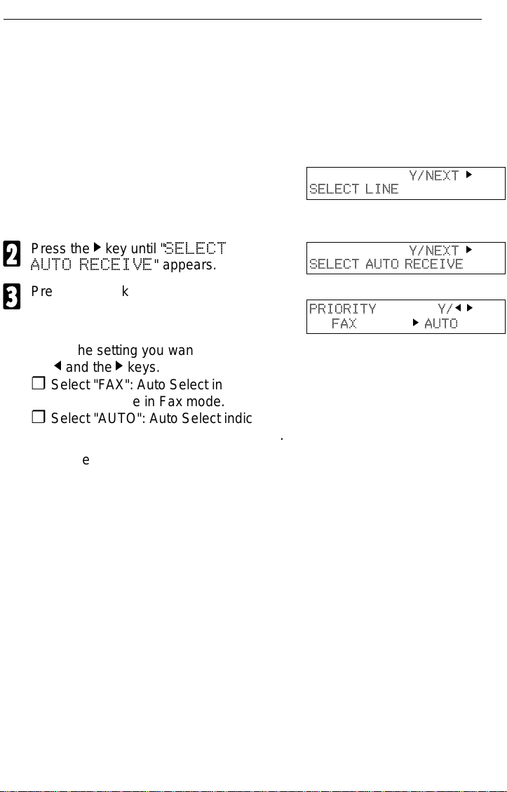
Press the k key until "
2
AUTO RECEIVE
Press the Yes key.
SELECT
" appears.
3
Select the setting you want using
4
and the k keys.
the
j
Y/NEXT
SELECT LINE
Y/NEXT
SELECT AUTO RECEIVE
PRIORITY Y/j
FAX k AUTO
k
k
k
❐ Select "FAX": Auto Select indicator
shows you are in Fax mode.
❐ Select "AUTO": Auto Select indicator
shows you are in Auto Receive mode.
Press the Function key.
5
Manual Receive Mode (Auto Select Not Lit)
This mode is active when the Auto Select indicator is NOT lit. Press the Auto
Select key to switch to and from this mode. You have to answer the call
yourself and decide whether it is a fax or a telephone call. The procedure for
answering a call is as follows:
Pick up the handset.
1
Listen to the other end.
2
❐ If you hear a voice, continue your conversation as you would normally.
❐ If you hear a fax tone, remove any docu me nt s fro m the feeder, press the
Start key th en replace the ha ndset. The mac hi ne will start r e ceiving.
12
Receiving Calls & Fax Messages(Faxes/Phone Calls) FAXING
Setting the Auto Ring Time
In Auto mode, the machine rings a number of times to give you the chance to
pick up the handset before taking the call automatically. You can alter the
number of rings by changing the Auto Ring Time.
Press the Function key and 6, 2,
1
2, 2, 2, 6, 1 using the ten key
pad, then press the Yes key.
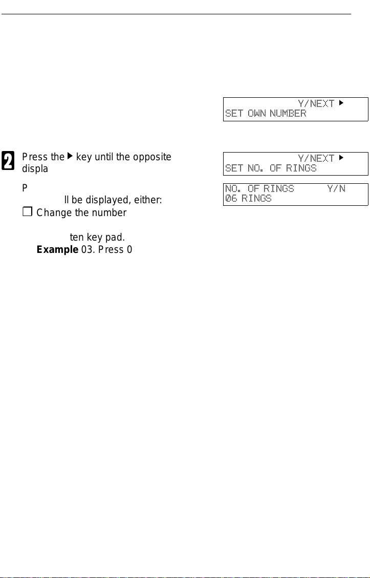
Press the k key until the opposite
2
display appears.
Press the Yes key. The factory
3
setting will be displayed, either:
Y/NEXT
SET OWN NUMBER
Y/NEXT
SET NO. OF RINGS
NO. OF RINGS Y/N
06 RINGS
k
k
❐ Change the number of rings, press the
No key, then press the new number using the ten key pad.
Example 03. Press 0, 3 using the ten
key pad.
❐ Keep these settings, go to step 4.
Press the Yes key, then the
4
Function key.
When you connect Telephone Answering Machine
When you are in Auto Mode, you can connect the Telephone Answering
Machine.
❐ Plug the answering machi ne int o the TEL jack on your f ax ma ch in e.
❐ Auto mode ensures that your answering machine has the chance to respond to
incoming telephone calls. If the call happens to be a fax message, the message
will be given to th e fax machine automatically.
❐ When you connec t t he telephone answering mach in e, the Auto Ring Time must
be set to one ring more th an the numbe r of rin gs tha t yo ur an swe ring machine
waits before it ta ke s th e ca ll . To check this number, have a friend call and do n ot
answer the phone, co un t th e nu mb er of ring s th at you hear before the answeri ng
machine ta kes the call.
13
FAXING Printing Received Messages that Have been Stored
(Substitute Reception)
Printing Received Messages that Have been Stored (Substitute Reception)
If the Receive File indicator is lit, a message was stored in memory using
substitute reception. This could be because the machine ran out of paper or
toner, or because the night timer has turned off the print engine.
Night Timer: Hold any key to print messages received while the Night Timer
(page 43) has turned the heater off. Otherwise, check if any of
the following indicators are lit, and follow instructions.
When ADD PAPER appears in the display, your fax machine is out of
paper . Add paper: see page 48.
When ADD TONER appears in the display, your fax machine is out of
toner. Change the toner cassette: page 49.
Or There might be a paper jam (see
page 56) or an open cover.
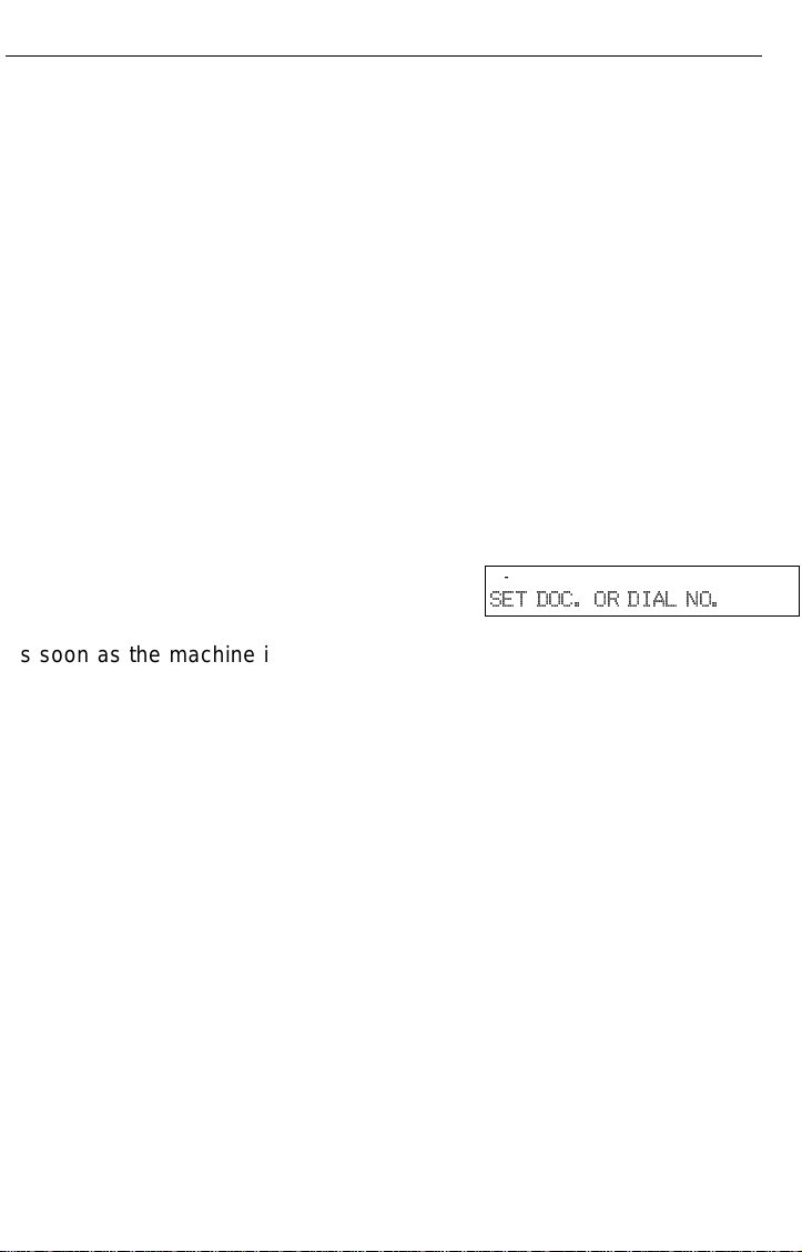
-Message appears here-
SET DOC. OR DIAL NO.
As soon as the machine is back in working condition, messages stored in
memory will be printed. The Receive File indicator will turn off and the
messages will be erased from memory.
If a message comes in while you are copying, the fax machine will store the
message in memory and the Receive File indicator will light. The message will
be printed as soon as copying is done.
To tur n substitute reception off or back on, set bit 0 of user parameter
switch 05. See page 66.
14

Faxing a Page With Very Fine Detail FAXING
Faxing a Page With Very Fine Detail
So that text , diagrams and images stand out clearly in your document, the
machine automa tically detec ts the image de nsity (contrast) and makes a
compensation.
However, if you need to send a document which requires optimum clarity,
select the resolution setting appropriate to your needs.
You can s elect different settings for each page of your message. Simply
change the settings for page 2 while page 1 is being scanned.
Resolution & Shading
The resolution button gives you control over document quality. The indicators
above the button show the current setting. Choose a setting that matches your
document.
Standard: Standard quality. Use for most printed or typewritten docu-
ments. This is selected when the other resolution indicators
are not lit.
Detail: High quality. Use for documents with small print or fine de-
tails.
Fine: Very high quality. Use this for high quality reproduction.
Halftone: Use this for optimum quality if your document contains
photographs/diagrams with complex shading patterns or gray
tones. If you choose this setting, resolution will automatically be
Detail.
Important: Faxing at a higher resolution requires more time. Frequent use of
high resolution could cause an increase in your phone bill, especially for long distance transmissions.
15
FAXING Optional Features for Transmission
Optional Features for Transmission
Send Later
Using this fe ature, you ca n delay transmission of your fax message until a
specified ti me. This allows you to take adva ntage of off-peak telephone line
charges without having to be by the machine at the time.
CAUTION: If your machine’s memory is full, you will have to send the mes-
sage from the document feeder. This means that anybody removing your document would automatically cancel the operation.
Proceed as for a usual fax message but don’t press Start.
1
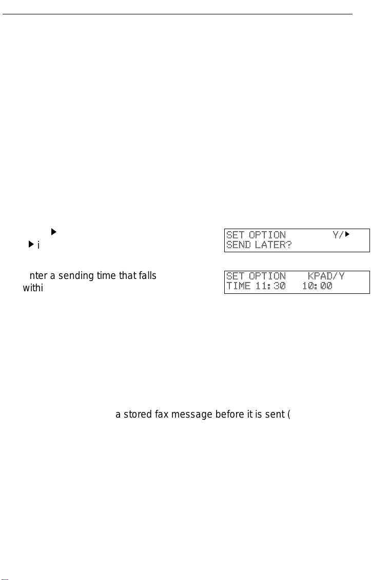
Press k once and press Yes.
2
( k is also the Option key).
Enter a sending time that falls
3
within the following 24 hours.
For example: To send at 11:30,
press 1, 1, 3, and 0 from the key
pad. If you enter the wrong time,
press No and enter again.
Press Yes.
SET OPTION Y/
SEND LATER?
SET OPTION KPAD/Y
TIME 11:30 10:00
4
Use function 21 to erase a stored fax message before it is sent (see page 28).
k
16
Optional Features for Transmission FAXING
Page Count (Immediate Transmission only)
When your fax message is p rinted at the other end, page numbers will b e
printed on the top of each page. Using the Page Count feature, you can select
the format in which the page numbers are printed.
If you use Page Count:
Page numbers will be printed in batch -numbering format (for example, p1/3,
p2/3, and p3/3 for a three-page message). This makes it easy for the other
party to see how many pages you sent, and if any are missing. However, you
have to input the number of pages at the keypad before sending.
If you do not use Page Count:
Page numbers wi ll be printed on ly as a sequence (for example, p1, p2, p3).
This makes it difficult for the other party to tell at a glance whether any pages
are missing (for exam ple, due to a do uble feed in your machine’s document
feeder).
Note:If you do not select Immediate Transmission, Page Count is automat-
ically switched on, and the pages are counted automatically.
If the numbering with page count appears strange, check that the page
count value matches the number of pages in your document.
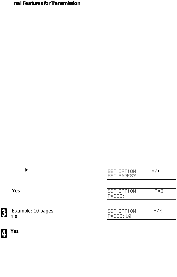
Press k until the right display ap-
1
pears.
Yes.
2
Example: 10 pages
3
1 0
Yes.
4
SET OPTION Y/k
SET PAGES?
SET OPTION KPAD
PAGES:
SET OPTION Y/N
PAGES:10
t t
17
FAXING Optional Features for Transmission
TTI
Normally, the TTI programmed in your machine is printed at the top of each of
the pages you transmit when they are received at the other end. The top of the
image will be ov erprinted if there is no margin at the top of the transmitted
page.
In some cases, you may wish the other party to receive an unmarked copy of
your original. In this case, you can switch TTI off.
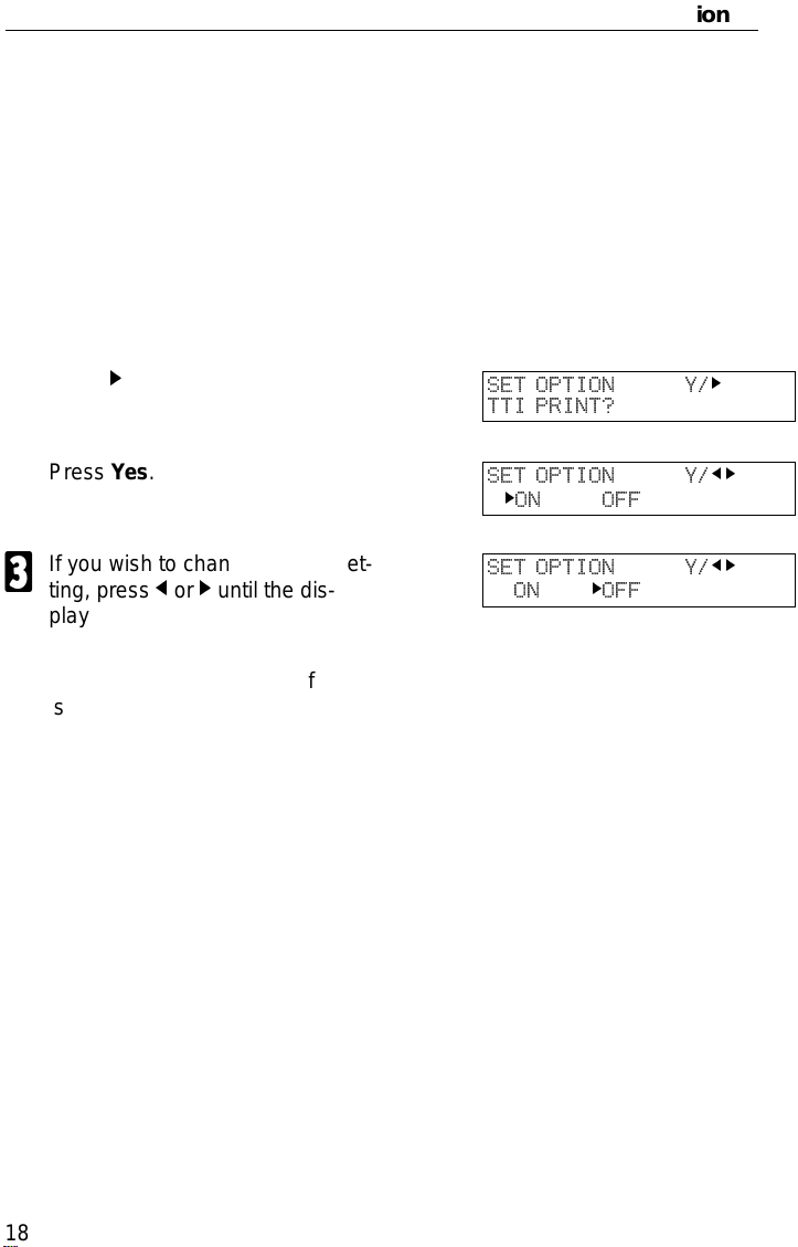
Press k until the right display ap-
1
pears.
Press Yes.
2
If you wish to change the TTI set-
3
ting, press j or k until the displayed setting is correct.
Press Yes when you have fin-
4
ished.
SET OPTION Y/
TTI PRINT?
SET OPTION Y/
kON OFF
SET OPTION Y/
ON kOFF
k
j k
j k
18

Redialing FAXING
Redialing
If a message was no t transmitted succe ssfully, that does not mean that you
have to enter the telephone n umber again. In many cases, the machine will
redial the destination automatically. Or, with the Redial key , you can r edial with
just a few keystrokes.
Automatic Redialing
The machine wi ll automatical ly redial the other party if any of the following
conditions occurred.
❐ The other party was busy
❐ There was no reply from the other party
❐ The message was rejected by the machine at the other end because of
excessive errors (in this case, redialing will only take place if Memory
Transmission was used)
The number of redials and the redial interval may be adjusted by a service
technician.
During redialing, the number being dialed is displayed as s hown on the below.
21255551234
DIALING
Using the Redial Key
The machine remembers the last telephone number that you input. If you have
to redial this number, just press the Redial key, then press the Start key.
This feature has the following uses.
If the machine is waiting to redial the other party, you do not have to wait for the
redialing interval to expire.
If you wish to send another message to the same address that you just sent
last time, you don’t have to dial the full number again.
Place the message in the feeder, then press the Redial key, then press the
Start key.
19

FAXING Redialing
To send a fax using Redial, do the following:
Make sure that the machine is in
1
standby mode for faxing. The display should look like this:
Set your document. How to set
2
the document, see page 7.
Press Redial.
3
Press Start.
4
READY 100% 10:00
SET DOC. OR DIAL NO.
REDIAL Y
2125551234
20

Storing & Editing Fax Numbers (Functions 31 & 32) FAXING
Storing & Editing Fax Numbers (Functions 31 & 32)
Numbers that you often use can be stored in memory. A stored number will
remain in memory even if the power is cut.
You can store numbers in three ways.
Quick Dials
The number is assigned to its own key. To dial that number , just pres s the key.
You can store up to 10 numbers in this way.
Speed Dials
The number is given a two digit code. To dial the number , press the Speed Dial
key and enter the code. There are 50 Speed Dial codes available numbered 00
to 49.
Groups
If you regularly broadcast messages to the same set of destinations, you can
combine these numbers into a group. Then just select the group and each
number will be dialled in sequence automatically. You can program up to 3
groups with 30 numbers each.
Storing, Editing and Erasing Quick Dials/ Speed Dials
These steps describe how to store or edit telephone number in Quick Dial
keys or Speed Dial codes. You can get a printout of numbers stored. In this
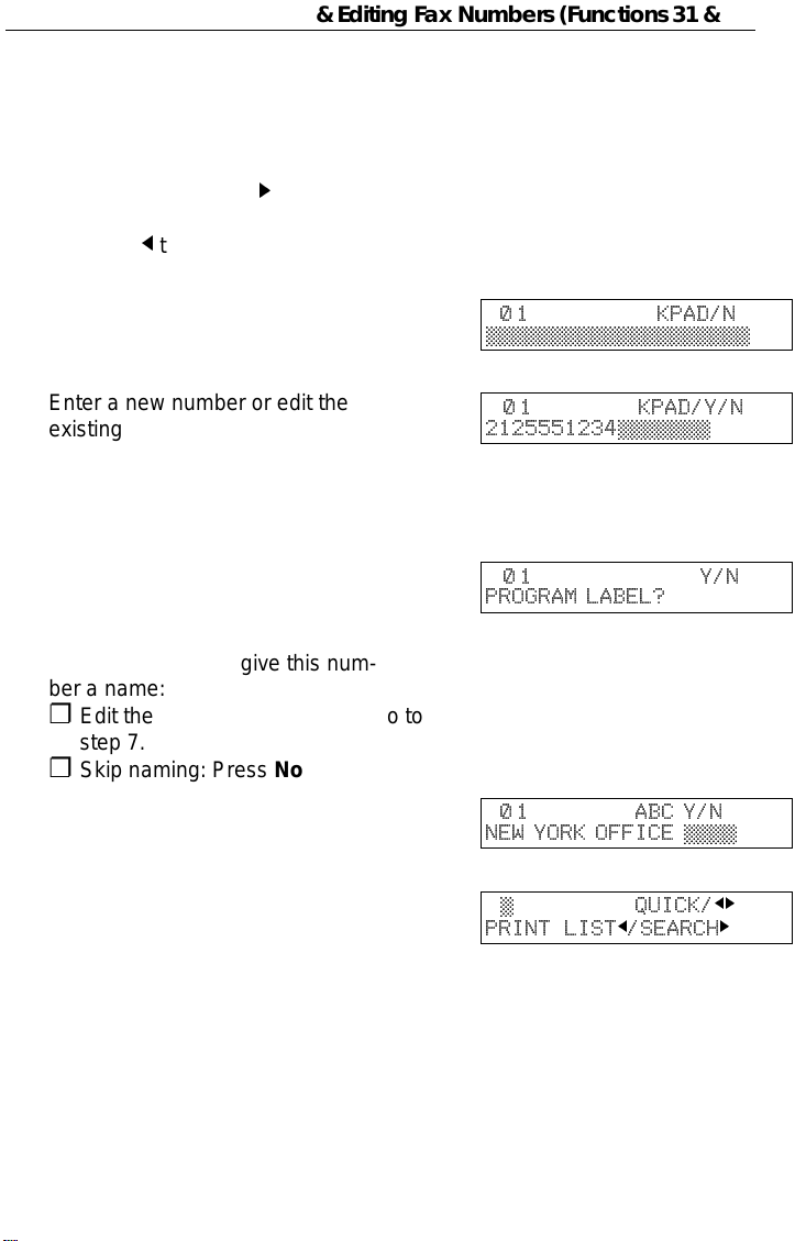
example we will store a new number in Speed Dial 01.
Choose Quick Dial or Speed Dial
1
programming mode.
❐ Quick Dial: Function 31 Yes
❐ Speed Dial: Function 3 2 Yes
Select the Quick Dial key or
2
Speed Dial code you want either:
n
© QUICK/
PRINT LISTj/SEARCH
N
© QUICK/
PRINT LISTj/SEARCH
jk
k
jk
k
❐ Quick Dial: Press the Quick Dial key
21
FAXING Storing & Editing Fax Numbers (Functions 31 & 32)
❐ Speed Dial: Input a two digit Speed Dial
code.
e.g. Speed Dial 01: Press 0 1.
❐ If the Speed dial code you select is al-
ready used, press k until an open code
appears.
❐ Press
bers.
j
then Start to print a list of num-
Press Yes to accept.
3
Enter a new number or edit the
4
existing number.
To erase an existing number,
press No then Yes and go to step
9.
Press Yes to accept.
5
If you wish you can give this num-
6
ber a name:
❐ Edit the name: Press Yes and go to
step 7.
❐ Skip naming: Press No and go to step 9.
Enter or edit the name. (See
7
page 71).
Press Yes to accept.
8
N
0 1 KPAD/N
©©©©©©©©©©©©©©©©©©©©
N
0 1 KPAD/Y/N
2125551234©©©©©©©
N
01 Y/N
PROGRAM LABEL?
n
0 1 ABC Y/N
NEW YORK OFFICE ©©©©
n
© QUICK/
PRINT LISTj/SEARCH
jk
k
❐ Edit another number: Go to step 2
9
❐ Return to standby mode:
Press Function.
22

Storing & Editing a Group of Fax Numbers (Function 33) FAXING
Storing & Editing a Group of Fax Numbers (Function 33)
This section describes how to program or edit a Group. You can also get a
printout of num bers that are already stored. In this example we will program
Group 1 into Quick Dial key 01.
You can store up to three groups numbered 1 to 3.
You can program up to 30 numbers in a Group.
Press Function, 3, 3, Yes .
1
Either:
2
❐ Enter the number of the group you want
to program or edit.
e.g. Group 1: Press 1.
❐ To print a list, press
Press Yes to accept.
j
then Start.
3
You have two options:
4
❐ Edit or program the Quick Dial key for
this group: Press Yes and go to step 5.
GROUP © 1-3/
PRINT LISTj/SEARCH
GROUP 1 Y/N
PROGRAM QUICK?
❐ Skip the Quick Dial: Press No and go to
step 6.
Then either:
5
❐ Program a new Quick Dial: Press the
Quick Dial key you wish to use for this
group then Yes.
❐ Free up the old Quick Dial: Press No,
then Yes.
If a message like "USED AS.." flashes up, the key is already in use.
Press a different key.
GROUP 1 Y/N
PROGRAM LABEL?
j k
k
23

FAXING Storing & Editing a Group of Fax Numbers (Function 33)
If you wish you can give this
6
group a name:
❐ Edit the name: Press Yes and go to
step 7.
GROUP 1 ABC
©©©©©©©©©©©©©©©©©©©©
❐ Skip naming: Press No and go to step 8.
Enter or edit the name then press
7
Yes.
Enter a fax number in one of
8
these ways:
❐ Press a Quick Dial key.
❐ Press the Speed Dial key followed by
two digits.
❐ Enter a number on the keypad.
Press Yes to accept.
9
If ALREADY PROGRAMMED
briefly flashes up on the display,
either:
❐ Press No to keep the number and
choose another number .
❐ Press Yes to erase this number from
the group.
You have two options:
A
❐ Enter another number: Go back to step
8.
❐ Finish entering numbers in this group:
Press No and go to step 11.
GROUP 1 KPAD/N
©©©©©©©©©©©©©©©©©©©©
You may then either:
B
❐ Work on another group: Go to step 2.
❐ Finish: Press Function.
24

Erasing Groups FAXING
Erasing Groups
These steps describe how to erase single numbers from a group.
Press the Function key and 3, 3
1
using the ten keypad, then press
the Yes key.
Enter the group number using the
2
ten key pad, then press the Yes
key.
Press the No key.
3
Press the No key.
4
Press the Yes key.
5
Either;
6
❐ Delete another number: Go to step 2
GROUP © 1-3/
PRINT LIST j/SEARCH
GROUP 1 Y/N
PROGRAM QUICK?
GROUP 1 QUICK/N
PROGRAM LABEL?
GROUP 1 Y/N
CLEAR?
GROUP 1 Y/N
CLEARED
j k
k
❐ Finish: Press Function.
Programming the Group Key
Y ou can progr am the 3 groups. However, if there is no room in Quick Dial keys,
this group key is helpful. You have to program the 10 of the Quick Dial key as
the group key. How to transmit using the group key, see page 8.
Press Funct ion 3 1 and Yes.
1
Press the Quick Dial 10.
2
Press Yes.
3
Press Yes.
4
Press Function.
5
n
© QUICK/
PRINT LISTj/SEARCH
n
10 PROGRAM?
n
10 PROGRAM? Y/N
PROGRAM GROUP KEY?
n
© QUICK/
PRINT LISTj/SEARCH
jk
k
jk
jk
k
25

FAXING Programming the Dial Option Key
Programming the Dial Option Key
This function of this key depends on the capabilities of the other terminal.
Press Function 3 1 and Yes.
1
Press the Quick Dial 09.
2
Press Yes.
3
Press Yes.
4
Press Function.
5
Dialling with the Dial Option Key.
Set the Document
1
Enter the number
2
Press 09 and Yes.
3
Enter the password
4
n
© QUICK/
PRINT LISTj/SEARCH
n
09 PROGRAM? Y/
n
09 PROGRAM? Y/N
PROG. DIAL OPTION?
n
© QUICK/
PRINT LISTj/SEARCH
TRANSMIT OPTION
DIAL FAX NUMBER
TRANSMIT Y/START
5551234
TRANSMIT Y/START
5551234W©©©©©©©©©©©©
TRANSMIT Y/START
5551234W9999©©©©©©©©
jk
k
jk
jk
k
k
Press 09 and Yes.
5
Enter the subaddress
6
Press 09 to enter space.
7
Note: You can program the password and sub-address in a Quick Dial, Speed
Dial or Group.
26
TRANSMIT Y/START
5551234W9999S©©©©©©
TRANSMIT Y/START
5551234W9999S1234©©
TRANSMIT Y/START
5551234W9999S1234

Chain Dialing FAXING
Chain Dialing
This feature allo ws you to compose a telephone number from various parts,
some of which may be stored as Quick Dial Keys or Speed Dial Codes, and
some of which may be input at the keypad.
For example, y ou can progra m commonly used area or country codes into
Speed Dial Codes or Quick Dial Keys.
Example: 01133-1-5553333 (From the USA to Paris).
Assume that the following Quick Dial and Speed Dial numbers have already
been programmed.
❐ Quick Dial 01 = 01133 (Overseas to France)
❐ Quick Dial 02 = 1 (Paris)
❐ Speed Dial 10 = 555
The machine ask you to dial
On Hook Dial or Handset Mode:
Press 01, 02, Speed Dial, 1, 0, then 3, 3, 3, 3.
Other:
Press 01, Pause, 02, Pause, Speed Dial, 1, 0, then 3, 3, 3, 3.
27

FAXING Erasing a Stored Message Before It Is Sent
(Functions 21 & 22)
Erasing a Stored Message Before It Is Sent (Functions 21 & 22)
Every time you store a fax message in your machine’s memory, a new file is
created. A file is also created for storing instructions to pick up a fax message
left elsewhere (polling, page 30). Each file is given a number. This number
appears on the memory st orage report, Journal and Transmission Result
Report. To see which files are currently in memory, you may print a file list.
To erase a fax message stored in
1
memory:
Press Function, 2, 1, and Yes
To erase instructions to
Or
message (polling):
Press Function, 2, 2, and Yes
Press k to scroll through the files.
2
You’ll get this.
Or: Press j to obtain a list of all the files and their number. If you already
know the number of the file to erase, enter it directly from the keypad
and skip to step 4.
Scroll through the files with j or k.
pick up
a
3
Press Yes.
4
Press Yes again to erase the file.
FILE NO.©©© KPAD/
PRINT LISTj/SEARCH
FILE NO.027 Y/
- number or label-
FILE NO.028 Y/
- number or label-
FILE NO.028 Y/N
CLEAR?
5
jk
k
jk
jk
6
Either:
❐ To erase another file, go to step 2.
❐ To finish, press Function.
28

Printing a Stored Message (Function 51) FAXING
Printing a Stored Message (Function 51)
If you need to see the contents of any of the files, use this feature.
Press Function, 5, 1, and Yes.
1
Press k to scroll through the mes-
2
sages. You’ll see this.
Or: Press j to obtain a list of all the files and their number. If you already
know the number of the file to print, enter it directly from the keypad and
skip to step 4.
Scroll through the message files
3
with j or k.
Press Yes.
4
Press Start to print the message.
FILE NO.©©© KPAD/
PRINT LISTj/SEARCH
FILE NO.115 Y/
-number or label-
FILE NO.116 Y/
-number or label-
FILE NO.116 START/N
-number or label-
5
jk
k
jk
jk
29

FAXING Polling Reception (Function 11)
Polling Reception (Function 11)
Use this feature when you wish to pick up a message from another terminal.
Press Function, 1 and 1
1
Press Yes.
2
Dial the number from where you
3
will pick up the message.
You can use Quick Dial keys or
Speed Dial codes.
Press Yes.
4
Press Start.
.
TRANS. MODE Y/NEXT
11 POLLING RECEIVE
POLLING RECV DIAL
DIAL FAX NUMBER
POLLING RECV Y/START
-number or label-
POLLING RECV START
-number or label-
5
Note: Another terminal should have the polling feature. You cannot poll
from a machine that has set secure polling with ID number. Ask the
other end to make a polling file without polling ID.
Deleting a Preset Polling Reception (Function 22)
k
Use function 22. For details, see Erasing a Stored Message on page 28.
30

Talking Before Sending a Fax(On Hook Dial) FAXING
Talking Before Sending a Fax(On Hook Dial)
Press the On Hook Dial key.
1
Proceed as for a usual fax message but don’t press Start. (Do not use
2
the handset).
If you hear a voice from the machine’s built-in speaker, pick up the
3
handset and speak to the other party.
If you hear a high-pitched tone instead of a voice, place your fax
message in the auto document feeder, then press Start.
When you are ready to send your fax message, place your message in
4
the feeder, then ask the other party to press Start.
When you hear a high-pitched tone, press Start.
5
Replace the handset.
6
Sending a Fax using the Handset
Yo u can send a f ax message us ing the handset. (External Telephone is
required.)
Set the document then pick up the handset.
1
Dial the other party.
2
If you hear a voice, speak to the other party.
3
If you hear a high-pitched tone instead of a voice, press Start.
When you are ready to send your fax message, ask the other party to
4
press Start.
When you hear a high-pitched tone, press Start.
5
Replace the handset.
6
31

OTHER FEATURES
Other features are listed here that you might find useful but that you will not set
very often.
Verifying Communications, Errors, Counters, etc. ............................................
Rejecting Messages From Certa in Send ers............ .. .. .. .............. .. .............. .. ...37
Saving Energy .................................................................................................42
Printing the Sender’s Identification....................................................................46
Tonal Signals ...... .. .. ...................................... .....................................................46
Copying................................................................................... ...........................47
Verifying Communications, Errors, Counters, etc.
You can obtain reports from your machine either by having your machine print
them out automatically, or by printing them out yourself.
Automatically Printed Reports
Unless ot herwise indica ted, the autom atic printing of these repor ts can be
turned on or off by changing the bit of the
Journal (Switch 03, bit 7)
This report gives details on each communication made by your terminal. It is
automatically output after 35 transmissions and receptions.
user parameters (see page 64).
File Reserve Report (Memory Storage Report) (Switch 03, bit 2)
If you switch this report on, it is printed immediately after you s tore a doc ument
in memory for Memory Transmission. It gives the file number, the time that it
was stored, and the destinations (including any Group numbers that were
selected).
Power Failure Report (Stays on)
This report is printed if the machine’s power was off for long enough to erase
files from the memory. The report gives details of the files that were lost. With
this information, you may store messages for transmission again, and contact
the senders of any received messages that were lost.
(Note: Phone numbers stored in Quick/Speed/Groups are not lost.)
32

Verifying Communications, Errors, Counters, etc. OTHER FEATURES
Communication Result Report (Memory Transmission) (Switch 03, bit 0)
This report is printe d out after memory transmission showing whether it was
successful or not. If you have switched this report off, a Communication Failure
Report will be printed only when a communication fails.
Transmission Result Report (Switch 03, bit 5)
This report is printed out after immediate transmission showing whether it was
successful or not.
Communication Result Report (Polling result report) (Switch 03, bit 4)
This repor t is printed af ter your machi ne polls a mess age from ano ther
machine.
Communication Failure Report (ON if Transmission Result Report is OFF)
This report is printed if a memory transmission failure occurred, after a job is
completed. It is only printed if the Transmission Result Report is switched off,
and event of a communication failure.
Error Report (Turned on/off by a Service Technician)
This report is printed after
communication failure report (above) is printed after a job has been completed.
So while doing a broadcast, the machine may print a number of error reports,
and at the end, it prints a communication failure or transmission result report.
Check it, and retransmit any pages that were not sent. If a particular problem
continues or gets worse, keep the error reports for the service technician.
each unsucces sful communication. The
Printing Part of the Image on the Report (Switch 04, bit 7)
For reference purposes, the machine prints the first few inches of the fax
message on the following reports.
❐ Transmission Result Report
❐ Memory Storage Report
❐ Communication Failure Report
33

OTHER FEATURES Verifying Communications, Errors, Counters, etc.
Report Formats
Example 1. Error Report*
* * * ERROR REPORT (AUG 01 1995 -06:00 ) * * *
FILE ADDRESS MODE TIME PAGE RESULT
--------------------------------------------------------------------
Report details appear here
TTI XYZ COMPANY
Example 2. Journal*
* * * JOURNAL (AUG 01 1995 07:00) * * *
<TX>
DATE TIME ADDRESS MODE TIME PAGE RESULT FILE
--------------------------------------------------------------------
<RX>
DATE TIME ADDRESS MODE TIME PAGE RESULT FILE
-------------------------------------------------------------------
The Mode Column
Transmission details appear here
Reception details appear here
TTI XYZ COMPANY
See the bottom of the Journal for a full listing of symbols on the Journal. On
other repor ts a code is giv en, informing t he type of co mmunication. These
codes are explained below.
The Result Column
OK: Successful communication
E: An error occurred
The Footnote on the Journal
TX counter: Total number of transmitted pages
RX counter: Total number of received pages
34

Verifying Communications, Errors, Counters, etc. OTHER FEATURES
Reports You Can Printout Yourself
You can print these reports at any time by following the steps below.
Journal (Function 41)
In addition to the automatic output of this report, which we’v e described earlier,
you can print the Journal at any time.
Press Function, 4, 1 and Yes.
1
Press Start to print out the report.
START
PRINT JOURNAL
2
File List (Function 42)
This is a list of memory transmission files still in memory. It gives information
about each stored file, such as the fax numbers, start time, and status.
Press Function, 4, 2 and Yes.
1
Press Start to print out the report.
START
PRINT LIST FILE
2
35

OTHER FEATURES Verifying Communications, Errors, Counters, etc.
Telephone Number List (Function 43)
You can obtain a list of all the phone numbers stored in the machine. (Y ou can
also obtain a list of stored numbers as you edit them. See the section on
storing numbers, beginning on page 21.
Press Function, 4, and 3.
1
Press Yes .
2
To print all the numbers (Quick Dial, Speed Dial, and Group numbers)
3
press Start. Then press Fu nct ion and skip the following steps. Three
lists will come out.
Or
Press No and you’ll see this:
Either:
4
If you want a Quick Dial list,
press Yes.
If you don’t press No.
Either:
5
If you want a Speed Dial list,
press Yes.
If you don’t press No.
REPORTS Y/NEXT
43 PRINT TEL LIST
ALL LISTS? START/N
QUICK/SPEED/GROUP
SELECT LISTS Y/N
QUICK DIAL LIST?
SELECT LISTS Y/N
SPEED DIAL LIST?
SELECT LISTS Y/N
GROUP LIST?
k
Either:
6
If you want a Group list, press
Yes.
If you don’t press No.
Press Start.
7
36
START
-Message appears here -

Rejecting Messages From Certain Senders OTHER FEATURES
Counters (Function 94)
These counters will help you if you wish to keep a regular check on how many pages your machine
has sent, received, and copied. The machi ne has the f oll owing count ers :
TX Counter: The number of pages that your machine has sent (transmitted )
RX Counter: The number of pages that your machine has recei v ed
Scan Counter: The number of pages that your machine has scanned (including copies )
Print Counter: The number of pages that your machine has printed
(including copies,reports and lists.)
Press Function , 6 , and enter the
1
access code 2222, then press 9,
4, and Yes.
Press Yes to check the SCAN
2
and PRINT counter.
Either:
3
❐ T o finish, press Yes twice.
❐ 1) If you have replaced the photoconductor
before REPLACE OPC appears (see page
52) then press Yes to reset the counter.
2) Press Clear.
3) Press Yes.
When you have finished, press Function.
TX :003256
RX :002648
SCAN :003287
PRINT :002703
Y/CLEAR
OPC
Y/CLEAR
OPC
4
Rejecting Messages From Certain Senders
Rejecting Messages From Senders Who Don’t Identify Themselves
Your fax machine can reject incoming me ssages lacking an identifier signal. Follow the user
parameter procedure on page 64 to enter these settings.
Switch 05, bit 1
0: Accept such messages 1: Rej ec t suc h mes s ages
Rejecting or Accepting Messages from Specified Senders
This feature is called A uthori z ed Rec eption. It helps you reject junk fax mail.
It lets you specify which terminals you wish to receive fax messages from; all others will be shut
out.
37

OTHER FEATURES Rejecting Messages From Certain Senders
1 - You must specify a list of senders (function 81). See page 39.
2 - You must turn Authorized Reception on (function 62). See page 41.
3 - You must set your machine to accept or reject messages from senders
in that list (user parameters, switch 08, bit 2 and 3; see page 41).
accept
If you
You accept messages only from a group of people you know.
If you
people in the list. This is useful to reject the junk fax mail.
them, the general public will not have access to your fax machine.
reject
them, everyo ne will be able to send you messages
except
the
You can store up to 30 identifications with this feature. You can program
an identifica tion and accept (or reject) messages from all senders whose
identification contains that part. See Wild Cards, page 95.
List of the
Authorized
Senders
(Function 81)
Empty
Empty/Not
empty
Not empty
Not empty
Authorized
Reception on/off
(Function 62)
On Either No messages are
Off Either All messages are
On Listed Only messages
On non-listed All messages are
Accept
messages from
special
terminals listed
or not listed
(Function 63)
Result
accepted.
accepted.
from special
terminals are
accepted.
accepted
from special
terminals.
part of
except
38

Rejecting Messages From Certain Senders OTHER FEATURES
Creating & Editing the List of Authorized Senders (Function 81)
Creating the List of Authorized Senders
Press Function, 6 and enter the
1
access code 2 2 2 2. Then, press
8, 1, and Yes.
(At this time, you can print an
Authorized Reception List by
pressing j and Start if it has already been created.)
Press Yes again.
2
Enter the sender’s RTI or CSI.
3
For example, enter "XYZ COMP ANY".
How to enter characters, see
page 71.
Press Yes.
4
To store this as a wild card, (see
5
glossary) press Yes, otherwise
press No. The word
GRAMMED
you’ll see:
will appear briefly. And
PRO-
SETTING? Y/
PRINT LISTj/SEARCH
RTI/CSI ABC
©©©©©©©©©©©©©©©©©©©©
RTI/CSI ABC Y/N
XYZ COMPANY
RTI/CSI Y/N
STORE AS WILD CARD?
RTI/CSI ABC
©©©©©©©©©©©©©©©©©©©©
jk
k
jk
jk
Go back to step 3 to enter another RTI or CSI or press Function if you
6
are done.
39

OTHER FEATURES Rejecting Messages From Certain Senders
Editing the Authorized Senders
Press Function, 6 and enter the
1
access code 2 2 2 2. Then, press
8, 1, and Yes.
Press k to scroll the RTI/CSI.
2
When the RTI/CSI you want to delete appears, press Yes.
Edit the RTI/CSI of the special ter-
3
minal.
j
and k to move the cursor.
Clear to delete one character.
No to delete the whole characters.
How to enter characters, see
page 71.
Press Yes.
4
To store this as a wild card, (see
5
glossary) press Yes, otherwise
press No. The word
GRAMMED
Press Yes and Function.
will appear briefly.
PRO-
6
Erasing the Authorized Senders
SETTING? Y/
PRINT LIST j /SEARCH
RTI/CSI ABC Y/N
XYZ COMPANY
RTI/CSI ABC Y/N
ABC COMPANY
RTI/CSI Y/N
STORE AS WILD CARD?
RTI/CSI ABC
©©©©©©©©©©©©©©©©©©©©
tt t t t
tt t t t
j k
jk
k
Press Function, 6 and enter the
1
access code 2 2 2 2. Then, press
8, 1, and Yes.
Press k to scroll the RTI/CSI.
2
And the RTI/CSI you want to delete appears, press Yes.
Press No and Yes.
3
Press Function.
4
40
SETTING? Y/
PRINT LIST j /SEARCH
RTI/CSI ABC Y/N
XYZ COMPANY
tt t t t
j k
k

Rejecting Messages From Certain Senders OTHER FEATURES
Switching Authorized Reception On or Off (Function 62)
Before you use Authorized Reception, you have to switch the feature on.
Press Function, 6 and enter the
1
access code 2 2 2 2. Then, press
6, 2, and Yes.
Press k until the screen is as
2
shown at right.
Press Yes.
3
Press j or k to change the on or off setting.
Y/NEXT
SELECT LINE
Y/NEXT
AUTHORIZED ON/OFF
AUTHORIZED Y/
k
ON OFF
k
k
jk
4
Press Yes and Function.
5
Accepting or Rejecting Messages From Senders in the List
You can choose to accept or reject messages from senders in the list. Follow
the user parameter procedure on page 64 to enter the following settings.
Switch 08, bit 2
You have to set it "1"
Switch 08, bit 3
0: Accept calls from senders in the list of authorized senders.
1: Reject calls from senders in the list of authorized senders.
Hints for Using Authorized Reception
You must specify the sender ’s identification code (their CSI or RTI, see page
87) which could be a little different from their phone number.
To get t he other party’s ide ntification, call and as k for their CSI or RTI code.
Explain that you need the number programmed into their fax machine for
identification purposes. Or, attempt a communication with their fax machine
and print out a transaction confirmation report ( function 41, see page 34). Read
the identification under the RTI or CSI heading of the report.
41

OTHER FEATURES Saving Energy
Saving Energy
To print a fax message your fax machine uses a heating roller to fus e the image
to the paper. This roller must already be hot when the paper passes under it.
To maint ain a temperatu re high enough to permit proper fusing, electricity is
consumed. This facsimile is equipped with various energy saving modes to
reduce the consumption of electricity while the machine is waiting for a fax
message.
Letting the heating roller cool to room temperature will reduce the amount of
electricity the fax machine consumes. However, the fax machine will not print
incoming messages right away, it will store them in memory and print them out
after the roller warms up.
Letting the heating roller cool halfway reduces the amount of electricity the fax
machine consumes, but not as much as letting it cool to room temperature. On
the other ha nd, since warmi ng up takes onl y a short time, incoming fax
messages can be printed right away.
If your fax machine enters saving energy mode, SA VING ENERGY appears on
the display.
The saving energy mode is related to the Night Timer. Refer to the section titled
"Night Timer".
How to start the saving energy mode
Your machine will enter the saving energy mode when machine is not used for
5 minutes.
If you want to change the five minute period to one or three minutes, or if you
do not want your machine to enter the saving energy mode automatically,
please contact your service representative.
How to exit the saving energy mode
Your machine exits from the energy saving mode.
❐ When a fax is received. (If the night timer is on, the message will printed out
after the night timer ends.)
You can still send a fax while the machine is in saving energy mode.
Y ou can also carr y out some functions (e.g. programming) by first holding down
a key to switch to standby mode.
42

Saving Energy OTHER FEATURES
Which saving energy mode is best for you?
You have two choices: You can let the roller cool to room temperature or you
can let it cool to the midpoint. To choose which of the two settings you would
prefer, set the user parameter switch.
When you allow the roller to cool to room temperature, energy savings are at a
maximum and printing will take a little longer since the roller will take more time
to come to printing temperature. When you select the midpoint, some energy
savings will still be achieved and printing will occur more rapidly.
Switch 05 bits 6 & 7
Letting the heating roller cool to room temperature: Bit 6 at 0, Bit 7 at 0
Letting the heating roller cool halfway: Bit 6 at 1, Bit 7 at 0
Saving Energy with the Night Timer
Y ou can set sleep time to let the machine go to saving energy condition and set
the wake up time when it returns to standby mode the next morning. During this
Night Timer mode, a fax message received is stored in the memory and will be
printed automatically the next morning after the wake up timer is activated.
As a typical example, you could program the heating element inside the pr inter
to stay off at night and over the weekend. (You can program different settings
for every day of the week.)
To use the Night Timer, you must:
1. Program the timers for each day of the week.
2. Switch the Night Timer feature on.
43

OTHER FEATURES Saving Energy
Setting the Timer (Function 71)
Caution: While the night timer is active, all incoming calls are refused if the
memory fills up.
Example: For T uesday, set the Night Timer to switch the heater on at 9 am and
off at 6 pm.
Press Function, 6 and enter ac-
1
cess code 2 2 2 2. Then, press
7,1 and Yes.
Press Yes.
2
Use the j and k keys to scroll
3
through the days of the week.
Example: Press k twice to go to
Tuesday.
Press Yes.
4
There are two timers for each day, each with an ON/OFF setting. "ON"
5
means that the heater will switch on at the time indicated. "OFF" means
that the heater will switch off at the time indicated. To change the ON to
OFF, or the other way round, press ∗ or #. When the ON/OFF display is
correct: Go to step 6.
Y/N
SET NIGHT TIMER
SET TIMER Y/N/
SUN
SET TIMER Y/N/
TUE
TIMER#1 TUE ∗/#/Y
ON FROM 00:00
j k
j k
Press k to move the cursor under
6
the time.
Input the time(9:00): Press 0, 9,
7
0, and 0 from the key pad.
44
TIMER#1 TUE KPAD/Y
ON FROM 00:00
TIMER#1 TUE ∗/#/Y
ON FROM 09:00

Saving Energy OTHER FEATURES
Press Yes.
8
Repeat step 5 to 7 for the second timer (18:00)
S
TIMER#2 TUE ∗/#/Y
ON FROM 00:00
9
Tip: If you want the heater on all day, set both timers to ON = 00:00.
If you want the heater off all day, set both timers to OFF = 00:00.
Either press Yes and Function to finish, or go back to step 3 to program
A
the timer for another day.
Switching the Night Timer On or Off (Function 62)
The Night Timer feature must be switched on using Function 62.
Press Function, 6 and enter ac-
1
cess code 2 2 2 2 . Then, press
6, 2 and Yes.
Scroll through the list of features
2
with k until the screen is as
shown opposite.
Press Yes.
3
Y/NEXT
SELECT LINE
Y/NEXT
NIGHT TIMER ON/OFF
NIGHT TIMER Y/
ON kOFF
k
k
j k
Change the on/off setting by
4
pressing j or k.
Finish: Yes and Function.
5
NIGHT TIMER Y/
k
ON OFF
j k
45

OTHER FEATURES Printing the Sender’s Identification
Printing the Sender’s Identification
This feature
CSI or RTI, see page 95) that appears on the display.
prints
at the top of the message, the sender’s identification (the
Tonal Signals
On this model the i key on the ten keypad is used as the Tone key. Some
organizations offer you a special service by telephone, which you can access
by transmitting Touch tone or DTMF tones. If your phone service provides only
pulse dialing, or if you are calling over a digital network, the ability to generate
Tonal Signals will allow you to access these services. First, dial the other party
When you are through to the other end, press the Tone key and enter the code
number that is needed to access the required feature at the other terminal. You
do not need to press the Tone key if your machine is set up for dialing in Tone
Dial (DTMF) mode.
Using the Tone Key
Make sure that the machine is in standby mode, and that there is no
1
document in the feeder.
Pick up the telephone handset, or press the On Hook Dial key.
2
Dial the remote facility. Do not press the Start key.
3
After your line is connected to the remote facility, do the following:
4
❐ If your telephone line type is DTMF (Tone Dial): Go to step 5.
❐ If your telephone line type is Pulse Dial: Press the
appears in th e display.
Input the digits that you need to use the remote facility. After you have
5
finished your business with the remote facility, hang up.
Note: Do not press the Start key.
46
i
on the te n keypad. A dot

Copying OTHER FEATURES
Copying
If you need to make a copy of something, and there is no copier available, use
your fax machine. Just place your original in the feeder, and press the Copy
key.
Note: When copying, the resolution is fixed as Detail.
Place your original in the feeder
1
Press Copy.
2
If you have the optional lower cas-
3
sette, you can select the paper
size by pressing k.
LT=letter LG=legal
The opposite display shows that
you select the Legal size.
Input the number of copies that
4
you need.
Example: 3 copies, press 3 of the
ten key pad.
Note: This machine makes copies in the order P1, P1, P2, P2 (for
example when making 2 copies of a 2 page document).
Press Start.
TRANSMIT OPTION
DIAL FAX NUMBER
COPY 01 SETS
k
LT A4
COPY 01 SETS
LT k A4
COPY 03 SETS
LT k A4
5
k
47

MAINTAINING YOUR MACHINE
Loading Paper in the Main Paper Tray
Caution: Make sure the paper conforms to the specifications on page 72.
Note: If any foreign matter (especially glue) is on the copy paper, print quality
may deteriorate. M ake sure the front, back and sides of the co py paper are
completely clean.
Place the paper on the tray, mak-
1
ing sure it is flush against the rear
and left walls.
Slide the paper guide to the left
2
so it lightly touches the paper.
Note: Whenever you change the paper size, set the paper size by Func tion 34
(see page 82).
Storage Condition of the Copy Paper
❐ 60 to 90 g/m
monly used
2
. copy paper is recommended: A4 size is the most com-
❐ Do not use damp paper or copies will be defective.
❐ Do not touch copy paper if your fingers are wet or oily; fingerprints may
appear on the copy.
❐ Keep paper in a vinyl bag if it will not be used for a long time.
❐ Store in a cool dry place.
❐ Store flat. Do not stand upright.
❐ The following materials cannot be used in the paper cassettes : Post
cards, tracing paper, OHP sheets, adhesive labels
❐ Do not overload the paper trays.
❐ If multi-sheet feeding occurs or dog-eared copies are made when using
recycled paper in the paper cassette, fan the recycled paper and load it
in the paper cassette again.
48

Replacing Toner Cassette MAINTAINING YOUR MACHINE
Replacing Toner Cassette
When the Check Display indicator starts to blink and TONER LOW appears in
the display, the toner cassette is almost empty. You will be able to make
roughly 100 more copi es before you have to re place it with a new cassette.
When ADD TONER appears in the display, it is time to install a new toner
cassette.
WARNING: Do not incinerate waste toner or depleted cassettes. Toner
dust might ignite suddenly if exposed to flames.
Caution: Lift the toner cartridge by the handle top.
Caution: Do not touch any parts other than those specified in the
procedure.
Squeeze in the release button on
1
the left of the machine and open
the cover.
Lift out the old toner cassette .
2
Shake the new toner cassette
3
from side to side before installing
it.
Put in the new toner cassette.
Make sure it drops in smoothly
and easily.
Close the cover firmly and pull
4
the copy output tray forward.
49

MAINTAINING YOUR MACHINE Replacing Toner Cassette
Storage Condition of the Toner Cassettes
❐ Store in a cool, dark place.
❐ Never store where they may be exposed to heat.
❐ Keep out of the reach of children.
❐ Do not eat toner.
❐ Do not lay heavy objects on toner cassettes.
❐ Do not incinerate toner or toner containers. Toner dust may cause flash-
back when exposed to an open flame.
50

Replacing the Photoconductor MAINTAINING YOUR MACHINE
Replacing the Photoconductor
The photoconductor receives the print image before it is transferred to paper.
To ensure optimal quality, replace it every 20,000 copies.
If the following display appears, it is time to replace the photoconductor.
REPLACE OPC
SET DOC. OR DIAL NO.
To check how many sheets you’ve printed, please refer the section titled
"Counters" (See page 37.)
Caution: Do not expose the photoconductor drum to light for an extended
period.
Caution: Do not open the cover or touch the PC drum : it cannot be re-
paired. Any scratch on the drum would be reproduced on prints.
Caution: Do not touch any parts other than those specified in the proce-
dure.
Caution: Though organic photoconductor drums are safe for the environ-
ment, dispose of used drums according to local regulations.
Squeeze in the release button on
1
the left of the machine and open
the cover fully back.
m
Lift out the toner cassette.
2
Remove the old photoconductor.
3
51

MAINTAINING YOUR MACHINE Replacing the Photoconductor
Unpack the new photoconductor
4
and put it into the machine.
The left and right ends are
marked "L" and "R" respectively.
Reinstall the toner cassette.
5
Close the cover firmly and pull
6
the copy tray forward.
Caution: Do not expose the new drum to light for an extended period of
time. Do not touch the surface of the drum.
After you replace the photoconductor, reset the counter for photoconductor
inside the machine.
If you have replaced the photoconductor before RELACE OPC appears, see
page 37 for how to reset the OPC counter (Function 94).
The display should be as oppo-
7
site.
Press m.
8
Press Yes.
9
The counter resets.
52
REPLACE OPC
SET DOC. OR DIAL NO.
Y/N
REPLACE OPC?
READY 100% 10:00
SET DOC. OR DIAL NO.
m

Daily Maintenance MAINTAINING YOUR MACHINE
Daily Maintenance
Caution: When wiping or cleaning components, do not use any sort of
cleaning agent or abrasive powder. Use a damp soft cloth to
clean and a dry soft cloth to wipe dry.
Cleaning the rollers
Grasp the center of the operation
1
panel and pull forward to open it.
Note: It is a good idea to steady
the machine.
While holding the panel open, wipe the two center rollers [A] and [B] with
2
a damp cloth.
To clean the hidden part of the white roller repeat the next 2 steps 5
more times.
1) Close the panel. The roller rotates automatically by about 60 °degrees
2) Open the panel and wipe the rollers.
Clean the exposure glass. [C]
[A]
[B]
[C]
Close the panel firmly and pull
3
the copy output tray forward.
53

T r oubleshooting
Caution: Do not attempt to make any repairs other than those described
in this manual. Removing covers may expose you to dangerous
voltages and other risks. Refer all servicing to qualified personnel.
Check the description in the display.
If an Indicator Lights Up on the Operation Panel
If COMM. ERROR PRESS STOP KEY appears in the display:
Press Stop.
The Receive File indicator is lit: You’ve received a fax message which is now
stored in the machine. See page 14 for instructions on how to print it out.
The Check Display indicator is lit: Read the message on the LCD display
and check the descriptions listed on page 62.
Other Possible Problems
You want to remove the document in the feeder
Open the document feeder (see page 53), then remove the document.
Caution: Do not pull out the document without opening the auto document
feeder, or you will damage the scanning mechanism.
54

Clearing Document Jams Troubleshooting
Clearing Document Jams
If
CLEAR ORIGINAL
Problem: There is a document jammed in the feeder. Remove the jammed
document and repeat the transmission procedure.
Cause: The document may be longer than the maximum limit (see the docu-
ment specifications on page 72).
Grasp the center of the operation
1
panel and pull forward to open it.
If the jammed paper is visible
2
from the document tray, pull it out
from the front of the machine.
If the jammed paper has been fed
right into the machine, hold the
panel open and remove it from inside.
appears in the display:
Close the panel firmly.
3
Pull the copy output tray forward.
4
Set the document again after
"READY" appears in the display.
55

Troubleshooting Clearing Copy Jams
Clearing Copy Jams
If
CLEAR COPY
CAUTION: Do not touch the fusing unit (see the diagram below). It may be
CAUTION: Do not touch the photoconductor drum (green drum).
CAUTION: Any toner on the paper will not be fixed to the paper. Be careful
CAUTION: Even if you can see the paper from the exit, do not pull it without
Squeeze in the release button on
1
the left side of the machine and
open the cover.
appears in the display, there is a copy jam. .
hot.
not to get your hands or clothing dirty.
opening the cover.
Carefully pull out the jammed pa-
2
per from the outside of the machine. Do not leave any pieces
inside.
If the document is very short you
might not be able to see it. In this
case remove the toner cassette
and photoconductor following
steps 2 to 5 on the page 51. Then
remove the jammed paper and reinstall the photoconductor and
toner cassette.
Close the cover firmly and pull
3
the copy tray forward.
56
Fusing Unit (white grill)

If Messages You Receive Don’t Fit on Your Paper Troubleshooting
If Messages You Receive Don’t Fit on Your Paper
Breaking Down Large Format Messages
If the incoming document is longer than the paper in your fax machine, the
machine will spl it it into mult iple sheets. The t ail end of the m essage will be
reproduced at the head of the next page. The images overlap each other by
10mm. (You can ask a service technician to turn off the overlap.)
Length Reduction
If the incoming document is too long but still within the limits below, the
machine can reduce it so that it will fit on one page.
Paper size in the cassette Maximum reducible length
Letter (11") 365.7mm
Legal (14") 464.8mm
A4 388.8mm
F 433.2mm
Communication problems
If
COMM. ERROR STOP
Causes: -A poor line caused the communication to fail.
-The line is busy or noisy. Try to retransmit.
-The other machine is out of order. Ask the other party to check
their machine.
appears in the display: Press Stop.
57

Troubleshooting Operational Difficulties
Operational Difficulties
Problem Required Action
STANDBY MODE
Nothing happens when the switch is
turned on.
Check the power cord. Is it properly plugged into
the outlet?
➣
SET DOC. OR DIAL NO. is not
displayed.
The display does not show the
Ready condition, or the machine
stops during operation.
Switch the power on.
➣
The machine might be in saving energy mode.
➣
Does CLEAR ORIGINAL or CLEAR COPY
appear in the display ?
➣
Does ADD PAPER appear in the display?
➣
Does CLOSE COVER appear in the display?
➣
TRANSMISSION
The original is not pulled into the
auto document feeder.
You did not feed the document far enough into
the feeder.
➣
Clean the ADF rollers (see page 53).
➣
Plug it in firmly
Check that the power cord is plugged in.
Hold down any key for two seconds.
Clear the misfeed. See page 56.
Load paper into the paper tray. See page 48.
Close all covers.
Insert the document into the feeder until it
stops. Retransmit.
If the same problem still exists after user
maintenance, contact your service
representative.
The machine cannot dial out. The telephone line is disconnected.
➣
Check that the line is connected properly.
The telephone line type setting is incorrect.
➣
Check the telephone line type setting
See page 84.
58

Operational Difficulties Troubleshooting
Problem Required Action
The machine cannot dial out from
behind a private switchboard (a
PBX).
Frequent original misfeeds Multifeeds or non feeds
The dialed number does not contain an access
code or a pause, or not enough pauses.
➣
Include the access number and a pause
before the telephone number, or add pauses
between the access code and the number,
if necessary.
Incorrect positioning of originals
➣
Put the document in the feeder correctly.
Incorrect alignment of originals
➣
Align the edges of the document.
Curled pages
➣
Flatten the document.
Incorrect document type
➣
Use a proper document type. See page 72.
Mixed document types
➣
The pages must all be of the same type.
Static electricity on the originals
➣
Shuffle the document.
Clean the ADF rollers (see page 53).
➣
If the same problem still exists after user
maintenance, contact your service
representative.
Copier silicone oil on the originals
➣
Wait a few minutes, then try again.
More than 30 pages in the feeder
➣
Do not place more than 30 pages in the
automatic document feeder at once.
The document may be longer than the maximum
limit (see page 72).
➣
Make sure that none of your originals exceed
this limit.
59

Troubleshooting Operational Difficulties
Problem Required Action
Transmission cannot take place The other machine is out of order.
➣
Check the error report.
➣
Ask the other party to check their machine
and correct the fault.
The line is busy or noisy.
➣
Check that the dial tone is sent out.
Try to retransmit.
Documents sent to other fax
terminals arrive blank.
The original must be placed
document feeder.
➣
Consistent difficulty in
communicating with a particular
terminal
Consistent poor image quality when
communicating with a particular
terminal
RECEPTION
The telephone keeps ringing and no
fax is printed.
There are some bad lines between you and that
other terminal.
➣
You are in Manual Receive mode.
➣
Power is switched off.
➣
RECEPTION/COPYING
No printout; the ADD PAPER
appears in the display.
The paper trays are empty.
➣
The metal plate in the optional paper feed unit is
not raised up.
➣
unit.
face up in the
Position the original correctly. See page 7.
Store that terminal’s number as a Quick Dial
Key or Speed Dial Code.
Then call a service technician. Inform him of
the nature of the problem and give the
Quick Dial Key or Speed Dial Code that you
stored the number in.
Change to Auto Select mode (see page 12).
Switch the power on.
Add paper (see page 48).
Press the buton on the left of the paper feed
No printout; the CLEAR COPY
appears in the display.
60
The printer has jammed.
➣
Clear the jam (see page 56).

Operational Difficulties Troubleshooting
Problem Required Action
Copies are blank. Is the toner cassette installed?
➣
Install the toner cassette.
Copy paper misfeeds occur
frequently.
Stripes on copies. The exposure glass for the auto document
TELEPHONING
Is the proper paper in the paper tray?
➣
Use appropriate paper. See page 72.
Is folded, wrinkled, damp, or curled paper in the
paper tray?
➣
Always use dry, undamaged paper.
Is the paper set properly in the paper tray?
➣
Always load paper correctly. See page 48.
Do not load too much paper in the trays.
Are there any pieces of misfed paper or other
foreign objects in the machine?
➣
Make sure that the paper path is
completely clear of paper and other
material after a misfeed.
Are you copying onto recycled paper?
➣
Fan the stack of recycled paper and load
it in the paper tray.
feeder is dirty.
➣
Clean the exposure glass (see page 53).
You can’t receive phone calls; the
unit only rings once then goes into
receive mode.
You can’t receive phone calls; the
unit does not ring.
POLLING
Dialing took place, but polling could
not.
You are in FAX mode.
➣
mode.
The telephone line is not connected.
➣
Polling with ID is set in the other terminal.
➣
Change to Manual Receive mode or AUTO
(see page 12).
Connect the line (see page 84).
Contact the person at the other end and
make sure that
free polling is available.
61

Tr oubleshooting Displayed Error Messages
Displayed Error Messages
CHECK AUTO-DIALING
NO FILE EXISTS
TOO MANY DEST.
USED AS GROUP
USED AS DIAL
USED AS DIAL OPTION
USED AS GROUP KEY
NOT PROGRAMMED
ALREADY PROGRAMMED
PLEASE SET PAUSE
TONER LOW
ADD TONER
ADD P APER
CLEAR ORIGINAL
CLEAR COPY
CLOSE COVER
SERVICE CALL
©-©©
You cannot use the auto-dialer at the moment. Use the ten-key
pad or the handset.
No polling reception operations have been programmed.
There are no messages in memory waiting for transmission.
Incorrect file number. Check the file number and try again.
The memory cannot hold any more telephone numbers.
Either: Delete some numbers then try again.
Or: Wait until some of the Send Later or other delayed
transmissions waiting in memory have been carried out, then try
again.
This Quick Dial Key has a Group stored in it.
This Quick Dial Key has a telephone number stored in it.
This Quick Dial Key is programmed as Dial Option Key.
This Quick Dial Key is programmed as Group Key
This Quick Dial Key or Speed Dial Code does not contain a
number.
Either:This number is already included in thi s Group.
This RTI/CSI has already been stored for use with this feature.
You must add a pause after your area code when you input your
fax terminal’s own telephone number.
Toner has nearly run out. You can still make copies but must
change the cartridge soon.
The toner cartridge is empty. Install a new cartridge.
The cassette is now empty.
A document is jammed in the feeder.
Paper is jammed in the printer.
A cover is not closed properly. Check that all covers are closed.
H Machine is out of order. Contact your service
representative. Be sure to write down the code numbers
and have it handy when you call for service.
j
CHECK PAPER SIZE The size of the installed paper does not match the
currently selected paper size.
Set the paper size (see page 82) or install the appropriate
paper.
62

Calling the Service Station Troubleshooting
Calling the Service Station
The machine ha s a feature ca lled Service Repor t Transmission. Use this
feature when your machine is having problems. The machine will transmit
information about the condition of your machine to your service representative.
A technician will then be able to find out what the problem is before making a
visit. Servi ce Report Transmission is available when the fax number of the
service representative has been programmed.
Sending a Service Report
When you need to send a service report, do the following.
Function 6 2 2 2 2 7 2 and Yes.
1
Start.
2
If the transmission was not successful, the machine will not redial. You must
repeat the operation. Program your machine’s own telephone number in order
for your service representative to identify the sender of the service report.
(Function 61: see page 88)
SYSTEM PARA. TX
5551234
DIALING
START
63

TECHNICAL REFERENCE
bit values
bit
Access Code for Functions 61 to 94
Accessing functions 61 to 94 requires an access code.
The sole pur pose of this feature is to keep others from accidentally
misadjusting the machine. This code cannot be changed, so do not rely on it as
a security feature.
The code is 2222
User Parameters (function 63)
Adjusting your machine sometimes requires that you change special settings
called user parameters. For each user parameter, you must change a
switch.
bit in a
Example:
A switch has eight bits. Each bit has a
0 to 7 from the right. In the following example we’ll change bit 3 of switch 05 in
the user parameters.
Press Function and 6, enter the
1
access code 2 2 2 2 then press
6, 3, and Yes. You’ll get:.
(You can press j to see a list.
Otherwise, press Yes.)
Press Yes again and use the j &
2
k
keys to change switches. For
example go to switch 05 by pressing k five times.
Switch
SW 01: 0000 1001
value
7 6 5 4
of 1 or 0, and each bit is
3 2 1 0
SETTING? Y/
PRINT LIST
KPAD/Y/
SWITCH 05 :1000 0001
numbered
j
j
jk
64

User Parameters (function 63) TECHNICAL REFERENCE
To change bit 3, press 3 on the
3
key pad. Bit 3 will change from 1
KPAD/Y/
SWITCH 05 :1000
1001
jk
to 0 or from 0 to 1.
(To change bit 0, press 0, to
change bit 1, press 1, and so on.)
Press Yes and Function.
4
Here is a list of all relevant user parameters. Many bit settings have no effect
and are not listed. (Never change these). The settings made at the factory are
underlined.
SW Digits & Definition Settings
00 0, 1, 2 and 3 Do not change these settings
4, 5: Default resolution when you
send a message
RESOLUTION
HALFTONE
6: Default setting for transmission
TRANSMISSION MODE
01 7: Clear modes after sending a fax.
RETURN TO HOME POSITION
Bit 4 5
Standard 0 0
Detail 1 0
Fine 0 1
Halftone 1 1
Memory: 0
Immediate: 1
Off: 0
On: 1
65

TECHNICAL REFERENCE User Parameters (function 63)
SW Digits & Definition Settings
03 0: Automatically print memory
transmission reports.
COMMUNICATION RESULT
REPORT (MEMORY TX)
2: Automatically print storage
reports for memory transmission.
FILE RESERVE REPORT
(MEMORY TX)
4: Automatically print polling
reception reports.
COMMUNICATIO N R ES UL T
REPORT (POLLING RX)
5: Automatically print immediate
transmission reports.
TRANSMISSION RESULT REPORT
7: Automatically print communication
reports.
JOURNAL
04 7: Include the first half of the first
page with reports?
INCLUSION OF PART OF IMAGE
05 0: Store incoming faxes when
machine is out of supplies.
SUBSTITUTE RECEPTION
1: Allow automatic reception from
senders that do not identify
themselves.
MEMORY RECEPTION
CONDITIONS OF
6, 7: Level for the Energy Saving
feature
ENERGY SAVING
Off: 0
On: 1
Off: 0
On: 1
Off: 0
On: 1
Off: 0
On: 1
Off: 0
Yes: 1
Off: 0
On: 1
Off: 0
On: 1
Accept (Free): 0
Reject (RTI/CSI): 1
Bit 6 7
Heater off: 0 0
Heater half cool: 1 0
06 0: Send a header with each page.
TTI
4: Batch Transmission Off: 0
66
Off: 0
On: 1
On: 1

User Parameters (function 63) TECHNICAL REFERENCE
SW Digits & Definition Settings
08 2, 3:
AUTHORIZED RECEPTION
(Can also use function 62)
Bits
2 3 :
0 X: Off
1 0: Receive messages only from
senders whose RTI/CSIs are
programmed.
1 1: Receive messages only from
senders whose RTI/CSIs are
programmed.
10 7: Use dithering halftone (SPD) or
standard halftone (STD)?
HALFTONE METHOD
STD: 0
SPD: 1
12 2: Faxing & Report Toner Saving Off: 0 On: 1
ECONOMY PRINTING MODE
Note:
If on, contrast will be set to "Normal" automatically, preserving image quality.
This is available when receiving fax messages and printing reports, but not
for copying.
Further, messages sent to you in halftone mode will automatically turn off
toner saving to insure a clear image.
To make sure that the fax quality is acceptable with toner saving on, print a
few reports.
(Note: If the sender is using a machine made by another manufacturer, toner
saving will stay on and this could lower image quality.)
3, 4: Fax reception
density
PRINT DENSITY
Bit 3 4
Normal: 0 0
Darken: 0 1
Lighten: 1 0
13 Access to the public telephone line Bit 0 1
Loop Start 0 0
Ground Start 0 1
(This feature is not available in
France.)
Flash Start 1 1
PSTN 0 0
67

TECHNICAL REFERENCE User Parameters (function 63)
User Parameter Hints
Changing your machine’s default settings
These are the settings your machine assumes immediately after it is turned on,
after clearing the machine, or after you or the night timer reactivates it. Many of
the user parameters determine your machine’s default settings.
Clear modes after sending or loading a fax message (Switch 01, bit 7)
Y our machine can either reset itself or keep its settings (for a few minutes ) after
it sends a fax message.
Automatic reports
Many types of automatic reports can be switched on or off. See page 32 for
details.
Accepting messages when out of supplies (Switch 05, bit 0)
This is also called substitute reception. You can accept messages even when
out of toner or paper by storing them in memory. See page 14 .
Saving toner (Switch 12, bit 2)
You can reduce the a mount of toner used for fax messages and for reports.
Messages sent to you in halftone (e.g. photographs) will switch this feature off
to ensure the best image quality available, but the feature will stay on if the
sender is using a machine made by another manufacturer. To make sure the
fax quality is acceptable, print a few reports (see page 32). If you find that your
fax messages and reports are too light, turn this feature off.
Adjusting the density for faxes (Switch 12, bits 3 & 4)
If your received fax messages are too light or too dark, adjust the printing
density over three levels: Normal, Darken, and Lighten.
68

Adjusting the Volume of Various Features TECHNICAL REFERENCE
Adjusting the Volume of Various Features (Function 92)
You can change the beeper (monitor) volume of the desired feature.
TRANS MONITOR
RECV MONITOR
ON HOOK MONITOR
DIAL MONITOR
Beeps to signal transmissions.
Beeps to signal receptions.
Beeps to signal on hook dialing.
Beeps when a number is dialed.
Press Function, 6, and enter the
1
access number 2222. Then press
9, 2.
Press Yes.
2
Adjust the transmission monitor
3
volume with j & k and press Yes
when you’re done.
Adjust the reception monitor vol-
4
ume with j & k and press Yes
when you’re done.
Adjust the on hook monitor vol-
5
ume with j & k and press Yes
when you’re done.
Adjust the dial monitor volume
6
with j & k and press Yes when
you’re done.
Press Function to return to the ready state.
7
ADJUSTMENT Y/NEXT
92 ADJUST VOLUME
TRANS MONITOR Y/
MIN
kkk
MAX
RECV MONITOR Y/
MIN
kkk
MAX
ONHOOK MONITOR Y/
MIN
kkk
MAX
DIAL MONITOR Y/
MIN
kkk
MAX
jk
jk
jk
jk
k
69

TECHNICAL REFERENCE Selecting the Display’s Language
Selecting the Display’s Language (Function 93)
If you would rat her use another la nguage for messages and displays, follow
the procedure below. The six languages available are: English, German,
Italian, Spanish, French, and Swedish.
Press Function, 6, and enter the
1
access number 2222. Then press
9, 3, and Yes.
Use j and k to scroll through the
2
available languages.
Press Yes to accept the language displayed, then press Function to
3
return to the ready state.
SELECT LANGUAGE Y/
ENGLISH
SELECT LANGUAGE Y/
FRENCH
Counters (Function 94, see page 37. )
jk
jk
70

Entering Characters TECHNICAL REFERENCE
Entering Characters
Use the key pad for entering numbers. Use Quick Dial keys 1 to 8 for entering
letter s, the j & k keys to change to another letter, the Yes key to accept a
character, and Quick Dial key 10 for spaces and other characters.
If at any time you make a mistake when entering a character or digit, press the
Clear key to erase it. To correct a character or number already entered, use the
j
and k keys to reach the mistake, enter the new character, and press clear to
erase the mistaken character. If you press the No key, whole characters are
erased.
Quick Dial Key Letters Quick Dial Key Letters
01 A --C 06 P - R
02 D - F 07 S - U
03 G - I 08 V - Z
04 J - L 09 Nothing
05 M - O 10 Space & Symbols
Entering Symbols
Press 10 of the Quick Dial key.
1
Press j or k to scroll symbols.
2
You can enter the following symbols.
"Space" & $ ! " # $ % & ’ ( ) * + , / : ; < > ? @ [ ¥ ] ^
Press Yes.
3
Entering Numbers
Enter numbers using the ten key pad.
1
71

TECHNICAL REFERENCE Document & Paper Specifications
Document & Paper Specifications
Documents (Using the Auto Do cumen t F eeder)
Length : 105~600mm
Width: 148~216mm
2
Thickness : 0.05 ~0.2mm (50 to 90 g/m
Document Feeder Requirements
)
❐ Do not insert torn, heavi ly curl ed , wavy , cre as ed , do g-e are d, damp, or otherwise
damaged documents . Ma ke copie s of the se orig in al s an d scan the cop ie s.
❐ Do not insert folded, st ap le d, cli pp ed , gl ue d, or tap ed doc umen ts , or do cu me nt s
with a metallic coating. Make copies of these originals and scan the copies.
❐ Do not insert document s on whic h th ere is undried ink or correctio n fluid. Wait
for the document to dry.
❐ If the document has an une ve n or slan ted edge, do not insert tha t ed ge in fi rst .
Paper Requirements
❐ Acceptable s iz es are letter , l egal, A4 and F4.
When a received fa x mess ag e is prin te d, a margin of 4mm on all four sides is
left blank. To avoid loss of informat io n, the sender should make sure their
message does not run over the se margin s.
❐ Do not print to torn, hea vi ly curl ed , wavy , cre as ed , do g-e ared, damp, or
otherwise damaged paper.
❐ Do not print to folded, stapled, clipped, glued, or taped paper.
❐ Do not print to paper with any kind of coating or printing. Do not print to metallic
paper. Do not print to the reverse side of a print.
72

Capabilities TECHNICAL REFERENCE
Capabilities
Functions That Can Be Used Together (Dual Access)
Job you wish to carry out at the same time
(Second selection)
Job currently in progress
(First selection)
1. Storing to Memory
2. Printing from Memory
3. Copying
4. Printing an Automatic Report
5. Immediate Transmission
6. Memory Transmission
7. Receiving and Printing a Fax
8. Receiving a Fax to Memory
9. Transmitting a Service Report
✔: Possible, ✖: Not possible
1. 2. 3. 4. 5. 6. 7. 8. 9.
✔✖✔✖✔✔✔✔
✔ ✖✖✖✖✖✖✖
✖✖ ✖✖✔✖✔✔
✔✖✖ ✖✖✖✖✖
✖✖✖✖ ✖✖✖✖
✔✖✔✖✖ ✖✖✖
✔✖✖✖✖✖ ✖✖
✔✖✔✖✖✖✖ ✖
✔✖✔✖✖✖✖✖
Stored Numbers (Long term)
❐ 10 Quick Dial keys, each of whi ch ca n h ol d a n i nd iv id ua l n umbe r. Any three of
the Quick Dial keys can ho ld a grou p of numbe rs.
❐ 50 individual numbe rs st ore d as two-d ig it Spee d Dial codes (see page 21).
❐ Three groups, each of which can hold up to 30 destinations.
❐ 30 CSI or RTI codes (po ssib ly use d as wild card s) fo r a ut ho riz ed rece pt io n.
Stored Destinations
❐ Y ou can send to as many as 30 locations for one job.
❐ Up to 100 destinations can be se t a t a ny on e t ime. (Ex: message A to 25
destinations, message B to 50, message C to 24 and finally one immediate
transmission job you’r e programming in no w. Total: 100)
73

TECHNICAL REFERENCE Specifications
File Storage
❐ You can have as many as 100 memory transmission files stored in the ma ch in e:
This is a theoretical maximum. The actual number of files you can have in your
machine depends on th e ty pe s of the doc umen ts , an d ho w muc h me mo ry th ey
consume.
Specifications
Electrical Specifications (Base machine)
Power supply: 220-240 Vac, 50Hz
Power consumption
Energy saver mode: Average 8 W
Standby mode: Average 24W
Transmission: Average 35W
Reception: Average 180W
Copying: Average 195W
Maximum power consumption: 470W
Fax Specifications
Protocol: G3
Memory Capacity: Base Machine: 18 pages/A4 size
With 1Mbyte memory: 102 pages
With 2Mbyte memory: 186 pages
Data rate: 14,400/12,000/9600/7200/4800/
2400 bps, automatic fallback.
Transmission time: 6 seconds at 14,400 bps, G3,
without TTI, ECM, MMR- using
memory for a ITU-T #1 test docu-
ment (Slerexe letter) at standard
resolution
74

Specifications TECHNICAL REFERENCE
General Specifications
Fax mode resolution: (main scan x subscan)
Standard: 8 x 3.85 lines/mm
Detail: 8 x 7.7 lines/mm
Fine: 8 x 15.4 lines/mm
Paper cassette capacity: 150 sheets (80g/m
2
Auto document feeder capacity: 30 sheets, face up
Paper Size: Letter, Legal, A4, F4
Dimensions (W x D x H): 380 x 341 x 219 mm
exclusive of trays, handsets, and options
Weight:
Optional Lower Paper Cassette
Capacity: 250 sheets (80g/m
7 kg
exclusive of trays, handsets, and options
2
Paper Size: Letter, Legal, A4
)
)
75

INSTALLATION
Before installing your machine, read the safety instructions at the beginning of
this manual. To install the machine, follow these procedures:
1-Find a suitable location for the machine.
2-Remove all the pieces of tape attached to the machine.
3-Install the photoconductor and toner cassette. (See page 78.)
4-Attach the accessories and load the paper in the paper tray. (See page 79.)
5-Connect the phone line. (See page 84.)
6-Connect the power. (See page 86.)
7-Enter all necessary information and settings in your machine’s memory.
(See page 87.)
Machine Environment
WARNING: When choosing a location for your machine, please follow the
safety instruction given on pages i to iv of this manual.
Location
For the best possible pe rformance, install your machine in a place which
satisfies the following conditions.
❐ Not exposed to direct sunlight
❐ Well ventilated (air turnover at least three times per hour); to avoid the
build-up of ozone, make sure to locate the machine in a large well-ventilated room which has an air turnover of more than 30 m
❐ Level
❐ Not subject to vibration
❐ Away from other electronic equipment, to avoid interference
❐ Away from areas containing corrosive gas
❐ Dust-free
❐ Condensation-free
❐ Temperature 15 to 25°C
❐ Humidity 35 to 70% RH (do not install near a humidifier)
❐ Away from heaters and air conditioners, to avoid sudden changes of
temperature
❐ Within 5 meters of a three-pin grounded power outlet (220-240 Volts,
50Hz)
3
/hr per person.
76

Machine Environment INSTALLATION
❐ Ensure there is clearance around the machine, as indicated in the dia-
gram below.
30cm
10cm
NOTE: This machine ge nerates a cer tain amount of ozone. Although the
amount generated is within safety requirements, it is recommended that, to
avoid ozone buildup, you install the m achine in a r oom which is pr operly
ventilated.
Operating Precautions
10cm
❐ While the machine is in operation, do not turn off the main switch or un-
plug the power cord.
❐ Keep corrosive liquids, such as acid, off the machine.
❐ Do not allow paper clips, staples, or other small metallic objects to fall in-
side the machine.
❐ The fusing unit may be very hot. Be careful when handling it.
77

INSTALLATION Installing the Photoconductor and Toner Cassette
Installing the Photoconductor and Toner Cassette
❐ First of all, remove all the pieces of tape attached with the machine.
Before us ing the machin e, install the photoconductor and to ner cassette as
follows:
Squeeze in the release button on
1
the left of the machine and open
the cover fully back.
Put in the photoconductor as
2
shown. The left and right ends
are marked "L" and "R" respectively.
Shake the toner cassette from
3
side to side before installing it.
Put in the toner cassette. Make
sure it sinks right down.
The right end is marked "2".
Close the cover firmly.
4
78

Installing the Main Paper Tray INSTALLATION
Installing the Main Paper Tray
Slide the paper guide to the mid-
1
dle.
Caution: Hold the guide at its
base to avoid damaging it.
Check you have the cassette the
2
right way up. Holding the tray at a
slight angle as shown, fit it into
the holes provided.
Important: Hold the tray angled
to the the right to avoid damaging
it.
Slide the paper guide back to the
3
right. And fit the wire as shown
below.
Attaching the Document Tray
Fit the wire into the holes pro-
1
vided.
79

INSTALLATION Installing the Auto Document Table
Installing the Auto Document Table
Fit the document table to the front
1
of the machine as shown.
Note: For long documents fold
out the wire extension.
Installing the Copy Tray
Hold the copy tray so it curves
1
away from you and fit it into the
holes provided.
Slant the left edge in first.
Pull the copy tray forward.
Note: For long paper fold out the
wire extension.
80

Installing the Optional Paper Feed Unit INSTALLATION
Installing the Optional Paper Feed Unit
Set the drawer in the cassette
1
and pull it fully out.
Set the guide in the slot appropri-
2
ate to the paper size you wish to
use.
To change the paper size, pull
back and lift out the paper size
guide. Then set the guide in the
slot appropriate to the paper size.
Press down the metal plate inside
3
the drawer.
Place the paper in the drawer so
4
it is flush with the rear wall. Do
not fill up the cassette past the
load limit marker.
Load limit
81

INSTALLATION Setting the Paper Size
half-moon shaped roller
Slide the draw until the paper just
5
touches the front and back of the
draw rightly.
Then press the button on the left
of the cassette to raise the metal
plate.
Make sure that the half-moon
shaped roller has its curved edge
on top.
Place the machine onto the paper
6
feed unit.
Warning: Watch your fingers!
Note: If any foreign matter (especially glue) is on the copy paper, print quality
may deteriorate. M ake sure the front, back and sides of the co py paper are
completely clean.
Setting the Paper Size
Use the following procedure to select which paper size the machine will use for
the printouts. For example if you wish to use Legal size paper, install the Legal
size paper into the feed. After done that, choose "LEGAL" using Function 34 or
j
key.
Press the Function key and 3, 4,
1
using the ten keypad, then press
the Yes key.
PAPER SIZE Y/
A4
j k
Or
Press the j key.
Current paper size appear in the
2
display. Scroll the paper size using the k key then press Yes.
82
PAPER SIZE Y/
LEGAL(8.5X14 INCH)
j k

Setting the Paper INSTALLATION
Either:
3
❐ If only one cassette is installed, press
Function to finish.
❐ If you have an optional lower cassette
installed, you will be prompt for the paper size. Repeat the same procedure in
the second step. And press Function to
finish.
2ND PAPER SIZE Y/
A4
j k
Setting the Paper
See the section titled "Setting / Adding the paper". See page 48 .
Installing the Optional Memory Card
Switch off the power before you install the optional memory car d.
Open the cover.
1
Insert the card with the side with
2
the card type (e.g. TYPE 20)
printed on it facing away (facing
right) from the machine.
Close the cover firmly and pull
3
the copy tray forward.
Turn the power back on.
83

INSTALLATION Connecting the Machine
Connecting the Machine
Before using the machine, connect the machine to the telephone line properly.
Then plug in the power cable and switch on.
Make sur e the m achine is prope rly connected to th e telephone line and the
power outlet, as shown below.
CAUTION
Do not switch on until everything is connected properly.
Program the Telephone Line Type setting (use Function 62; see page 90). If
your telephone normally sends out tones(touch tone) when dialing, use the TT
setting; if it normally sends out pulses (rotary dial), use the DP setting. Also,
make sure that the switch on the handset is set up correctly.
Connecting to the Phone Lines
84
[A]
[B]

Connecting to the Phone Lines INSTALLATION
Connect the phone line cord to the upper fax jack marked Line[A].
1
Connect the other end of the line into the phone line jack (on the wall or
2
on a cable).
Connect the handset (option) or your own telephone to the lower jack
3
marked Tel [B].
Connect the other end of the line to the handset or telephone.
4
85

INSTALLATION Connecting the Power
Connecting the Power
IMPORTANT POINTS ABOUT POWER CONNECTION
If you have to use an extension cord, make sure that it is capable of carrying
300V/10A, and that your facsimile terminal is the only piece of equipment
connected to that cord. The supply from the wall outlet must not fluctuate mor e
than 10 V either side of 230 Vac.
The power cord should not be laid in a place where it might trip somebody.
Do not lay anything on the power cord.
WARNING: The power source must conform to the specifications on page
74.
WARNING: Make sure the power source is properly grounded.
WARNING: Follow the safety instructions given of pages i to iv.
Insert the plug into the wall outlet.
1
Turn on the power.
2
Power Source
220-240 Vac.
50Hz
86

Initial Settings & Adjustments INSTALLATION
Initial Settings & Adjustments
Important: The CSI code (see below) is required by international law . You
cannot legally connect a fax machine to the telephone system if
the CSI code is not programmed. Further, the TTI code and the
date and time of transmission must be included in the header of
all pages faxed to, from, or within the United States.
Before you connect your machine to the telephone system, you must enter a
few settings and make a few adjustments.
Own number: The phone number used by your fax line.
CSI (Called Stat ion Identification , required by international law): This is your
fax machine’s phone number,
During any communication, your CSI appears on their display. (Conversely
their CSI appears on your display.)
RTI (Receive Terminal Identification): This should be your name or company
name, in 20 characters or less. During a communication, if the other party’s fax
machine supports RTI, then this replaces the CSI above. The other party’s
name will appear on your display, and yours on theirs.
which must in clude country and area codes
.
TTI (Transmitter Terminal Identification):This should be the same as your RTI
or CSI code. It will be printed on the header of every page you send.
Access number If you select inside line, you must program the number which
proceeds the telephone number.
Line: You must match the fax machine to the type of line you use: a tone line
or a pulse line. Then, you should connect the line to the machine.
Date & Time: Necessary for many functions and required in the USA.
Initial Settings (Function 61)
During the cou rse of this pro cedure you’l l have to enter letters and other
characters.
Use the key pad for entering numbers. Use Quick Dial keys 1 to 8
, the j & k keys to chang e to another letter, the Clear Key to erase a
letters
letter, Yes key to a ccept a characte r, and Quick Dial key 10 for spaces and
other characters. See page 71 for details.
for entering
87

INSTALLATION Initial Settings & Adjustments
If these settings have been made before, the messages on the display will not
always match those shown here. The setting already entered will appear along
with the word [
CHANGE?
]. In this case, press Yes to change the setting.
Press Function and 6, enter the
1
access code 2222, then enter 61.
You’ll get this:
Press Yes .
2
Press Yes again.
3
Enter your phone number.
4
INITIAL MODE Y/NEXT
61 INITIAL SET
Y/NEXT
SET OWN NUMBER
OWN NO. KPAD
©©©©©©©©©©©©©©©©©©©©
OWN NO. KPAD/Y/N
0111212-5551234©©©©©
❐ The format of the number is normally as follows:
International Dial Prefix, Your Country Code, Your Area Code, then you
must add a Pause, followed by your telephone number.
Check the International Dialing Prefix and the Country Code with your local telecommunications operator. The example shown is for the USA;
the codes to add are 011 and 1.
Press Yes.
5
flash on the display and you’ll get
Press Yes .
6
PROGRAMMED
will
Y/NEXT
SET RTI
RTI ABC
©©©©©©©©©©©©©©©©©©©©
k
k
k
Enter your office, company, or
7
personal name, or any other appropriate identification. (Use the
quick Dial keys. See page 71 for
details.)
Press Yes.
8
flash on the display and you’ll get:
88
PROGRAMMED
will
RTI ABC Y/N
XYZ COMPANY.
Y/NEXT
SET TTI
k

Initial Settings & Adjustments INSTALLATION
Press Yes. The RTI programmed
9
in step 7 appears. You should
keep it.
If you wish to change it, press
Yes and edit the TTI.
Press No to keep the TTI as is.
A
You’ll get:
Press Yes.
B
Enter your phone number and in-
C
clude the country and area code,
(but no pauses). Should be the
same as in step 4.
Press Yes.
D
flash on the display and you’ll get:
Setting the Access Number
Press the Function key and
1
press the Yes key.
PROGRAMMED
will
TTI CHANGE? ABC Y/N
XYZ COMPANY.
Y/NEXT
SET CSI
CSI KPAD
©©©©©©©©©©©©©©©©©©©©
CSI KPAD/Y/N
15145551234©©©©©©©©©
READY 100% 00:00AM
SET DOC. OR DIAL NO.
Y/NEXT
SET OWN NUMBER
k
k
Press the k key until the screen is
2
shown opposite.
Press the Yes key.
3
Enter the number which you use
4
to access an outside line.
Press the Yes key to store your setting, the press the Function key.
Y/NEXT
SET PSTN ACCESS NO.
NUMBER KPAD/N
©©
NUMBER KPAD
0 ©
5
k
89

INSTALLATION Initial Settings & Adjustments
Setting the Phone Line (Function 62)
Press Function and 6, enter the
1
access code 2, 2, 2, 2, then enter
62. You’ll get this:
Press Yes .
2
Press Yes again.
3
Press j & k to set your machine
4
for a tone dial line (
PD
dial line (
Press Yes .
5
flash on the display and you’ll get
this.
At this point, you could turn on
the Authorized Sender function
(page 37). We will skip this
Press Function.
).
PROGRAMMED
TT
) or a pulse
6
will
INITIAL MODE Y/NEXT
62 SELECT FUNCTION
Y/NEXT
SELECT LINE
SELECT LINE Y/
k
TT PD
SELECT LINE Y/
TT kPD
Y/NEXT
AUTHORIZED ON/OFF
READY 100% 10:00
SET DOC OR DIAL NO.
k
k
jk
jk
k
90

Initial Settings & Adjustments INSTALLATION
Setting the Date & Time (Function 91)
Press Function, 6, and enter the
1
access code 2222. Then enter
9 1.
Press Yes. A date and time will
2
appear.
Change the date with the ten key-
3
pad as 09.
Change the month using * or # (*
4
to scroll forward, or # to scroll
backward) on the ten key pad
and press k to move the cursor.
Type in the year and time at the
5
keypad as 9 6 1 0 2 5.
When the display is correct, press Yes and Function
6
ADJUSTMENT Y/NEXT
91 ADJUST CLOCK
MON KPAD/Y
22 JUL 1996 01:35
TUE KPAD/Y
09 JUL 1996 01:35
FRI */#/Y
09 AUG 19
FRI KPAD/Y
09 AUG 1996 10:
96 01:35
25
k
91

INSTALLATION Initial Settings & Adjustments
Daylight Saving Time
Whenever local custom requires advancing the clock or setting the clock back,
use this feature. You can easily move the clock forwards when daylight saving
time begins, and back when it ends.
When you install the machine for the first time, take care that the setting is
correct before you set the date and time.
Press Function, 6, and enter the
1
access code 2222. Then enter
6 2 then press Yes.
Press k until the screen is as
2
shown opposite, and then press
Yes.
Use the j and k arrows on the
3
scroll key to switch the feature on
or off. This mode is off if the display is shown as opposite.
To store your setting: Yes
4
Y/NEXTk
SELECT LINE
Y/NEXTk
SUMMER TIME/DTS
SUMMER TIME/DTS Y/
ON kOFF
j k
92

INDEX & GLOSSARY
Index
A
acceptable originals
minimum/maximum 4
access code 64
adding
paper 48
toner 49
answering machine
using with 13
authorized reception 37
authorized senders 37
Auto Select
reception 12
automatic
reports 32
B
broadcasting 7
C
characters
entering 71
clearing jams
copy/print 56
document 55
communication
capabilities 73
problems 57
connection
power 86
contrast
faxing 15
copy tray
installing 80
copying 47
Correcting Mistakes
Dialing 54
counters 37
CSI 87
D
date & time 91
Daylight Saving T im e 92
default settings 68
density
fax printouts 68
faxing 15
detailed document
faxing 15
dialing 8
document
specifications 7 2
Document Feeder
Acceptable originals 4,5
faxing 7
Document size, allowable 4
document table
installing 80
document tray
installing 79
Document types, allowable 5
dual access 73
E
environment (machine) 76
erasing
stored message 28
F
faxing 3-31
broadcasting 7
chain dialing 27
document feeder 7
send later 16
to one destination 7
file
report 35
function
21 erasing a stored message
28
22 erasing a polling job 28
31 setting a quick dial 21
33 setting a group 23
41 Journal 35
42 file report 35
43 stored number report 36
51 printing a stored message
29
62 initial settings 41,45,90
63 user parameters 64
71 night timer 44
81 authorized senders 39
91 date & time 91
92 sound volume 69
93 language 70
94 counters 37
function
61 initial settings 87
G
Grounding iii
groups
storing groups 23
using groups 8
H
handset
on hook dial 31
I
indicators 1
initial settings
general 87
Installation 76
J
jams
copy/print 56
document 55
Journal 32,35
K
keys 1
L
labels
entering characters for 71
language 70
LCD 1
length reduction 57
Lightning protection i ii,iv
93
 Loading...