

Ricoh FAX2700L Technical Bulletin FX3800
Model:
FR6
TECHNICAL BULLETIN
No:
Date:
31-Oct-97
001
1/35
Subject:
From:
New Model FR6 Release
Technical Service Department
Classification:
Troubleshooting
Mechanical
Paper path
Other ( )
Part information
Electrical
Transmit/receive
Prepared by:
Checked by:
Action required
Service manual revision
Retrofit information
K. Misugi
S. Fujii
The new model FR6 (FAX3800L) has been released as a successor model to the FX6
(FAX2700L).
This technical bulletin contains information on differences between the FR6 and the FX6.
They are listed in order of sections that appear in the service manual.
1. OVERALL MACHINE INFORMATION
1.1. SPECIFICATIONS
Item FX6 FR6
Maximum Scan Width
216 mm [8.5 ins] ± 0.25% 256 mm [10 ins] ± 0.25%
(Effective Scan Width: 250 mm [9.8 ins])
Memory Capacity (SAF) 244 kbytes
(19 pages/ITU-T #1 Char t)
Compression MH, MR, EFC, MMR, SSC MH, MR, MMR, SS C
Modulation V.29, V.27, V.21 V.34, V.17, V.29, V.27ter, V.21
Data Rate 9,600/7,200/4,800/2,400 bps 33,600/31,200/28,800/26,400/
Transmission Time 9 s at 9600 bps; G3 ECM,
ITU-T # 1 Chart, STD
Paper Feed Unit Not Available Optional Paper Feed Unit Available (500
0.5 Mbyte
(40 pages/ITU-T #1 Char t)
With 1 Mbyte memory card:120 pages
With 2 Mbytes memory card: 200 pages
With 4 Mbytes memory card: 360 pages
24,000/21,600/19,200/16,800/
14,400/12,000/9,600/7,200/4, 800/
2,400 bps
Automatically adjusted in accordance
with V.34,
Automatic fallback t o V.17, V.29, V.27ter
3 s at 28,800 bps: G3 ECM, ITU-T # 1
Chart, STD
sheets, Letter, Legal)
1

1.2. FEATURES
The following features are available.
Features FX6 FR6
Confidential Reception Available with memory card Standard
Batch Transmission Available with memory card Standard
Economy Transmission Not available Standard
Forwarding Available with memory card Standard
Personal codes with Conf. ID Available with memory card Standard
Transmission Deadline (TRD) Available with memory card Standard
Two in one Not available Available
Checkered mark Not available Available
Confidential ID Available with memory card Standard
Memory Lock (ID) Available with memory card Standard
Multi-Sort Document Reception Available with memory card Standard
TECHNICAL BULLETIN
Reverse Order Printing Available with memory card Standard
User Function Keys Not available Available (2 keys)
Confidential File Report Available with memory card Standard
2
1.4. OVERALL MACHINE CONTROL
TECHNICAL BULLETIN
The FCE contains the FCIP2, DRAM, SRAM, System ROM, MN195003MFL modem, and
video processing memory. It controls the entire system through the FDU.
The FCIP2 does not contain the modem block. The Panasonic MN195003MFL modem is
used for all the communications (V.34, V.17, V.29, V.27ter., and V.21).
The 2 MB DRAM contains the SAF memory, ECM buffer memory, work area, and page
memory. The SAF memory can be extended by 1, 2 or 4 Mbytes with an IC card option.
A 1 MB (8 Mbit) flash ROM is used for the system ROM.
The FR6 uses two CPUs in the same way as the FX6. These are the main CPU in the
FCIP2 and the power saver CPU which is used during the 2 W power saver mode.
The main differences in PCB components between the FR6 and the FX6 are listed below.
FX6 FR6
FCIP used FCIP2 used
(The FCIP2 is used in common with
the LFO.)
FCE Rockwell R144EFXL modem used. Panasonic MN195003MFL modem
used.
512 kB (4 Mbit) flash ROM used. 1 MB (8 Mbit) flash ROM used.
1 MB DRAM used. 2 MB DRAM used.
FDU FPD motor driver used. SLA7024M motor driver used.
3

1.5. VIDEO DATA PATH
1.5.1 Transmission
TECHNICAL BULLETIN
Immediate Transmission:
Scanned data from the CIS passes to the DIP block in the FCIP2. After analog/digital
video processing, the DCR block compresses the data for transmission. The compressed
data then passes either to the FIFO memory or to the ECM memory before it is sent
through the modem. The MN195003 modem is used for all the communications.
Memory Transmission:
The scanned data is stored in the SAF memory after compression in the DCR block.
At the time for transmission , the DCR block decompresses the data from the SAF
memory, then compresses it again after handshaking with the other terminal is done. The
compressed data then passes either to the FIFO memory or to the ECM memory, before it
is sent.
Parallel Memory Transmission:
This feature allows the machine to scan a document into the SAF memory and send the
same document simultaneously.
The machine stores the processed video data in the SAF memory and sends the data
through the modem at the same time.
4

1.5.2. Reception
TECHNICAL BULLETIN
Data from the line passes to the modem through the NCU and hybrid IC. After the modem
demodulates the data, the decompressed data passes to the DCR block, through either
the FIFO or the ECM memory, where the data is decompressed to raster image data. At
the same time, the compressed data passes to the SAF memory as a backup in case of
mechanical problems during printing (substitute reception).
The raster image data is then passed to the page memory for printing. After a page of
data has been stored in the page memory, the data is sent to the LDDR through the LIF
block.
5

TECHNICAL BULLETIN
2. DETAILED SECTION DESCRIPTIONS
2.3. SYSTEM FEATURES
2.3.2. Automatic Service Calls
The following RAM addresses are different from the FX6.
2. Excessive Jam Alarms
Parameters Address (H) Initial
Settings
ADF Printer
DEC
(1 - 255; 0 = Disabled)
CALL
(3 - 15; 0 = Disabled)
CLR
Counters Address (H) Sys. Para.
JAM:
Jam counter used to place
a service call
NO-JAM1:
JAM counter decrement
NO-JAM2:
clearing the JAM counter 8001F0 (High) 8001F4 (High)
Counter used for
Counter used for
(Low)
(High)
8001F5 8001F9 10 (H) X
8001F6 8001FA 06 (H) Y
8001F7 8001FB 30 (H) –
8001F8 8001FC 00 (H)
ADF Printer
8001EE 8001F2 Z
8001ED 8001F1 –
8001EF (Low) 8001F3 (Low) –
3. Periodic Service Call
Sys. Para.
List
List
Parameters Address (H)
Call interval: 01 through 15 month(s) (BCD)
00: Periodic Service Call Disabled
Date and time of the next call
Year: last two digits of the year (BCD) 800267
Month: 01 through 12 (BCD) 800268
Day: 01 through 31 (BCD) 800269
Hour: 00 through 23 (BCD) 80026A
4. PM Call
Address (H) Bits 7 - 4 Bits 3 - 0
80019A Tens Units
80019B Thousands Hundreds
80019C Hundred thousands Ten thousands
800266
6

5. Effective Term of Service Calls
Year: last two digits of the year (BCD) 800271
Month: 01 through 12 (BCD) 800272
Day: 01 through 31 (BCD) 800273
TECHNICAL BULLETIN
Address (H)
7
2.4. PCBs
2.4.1. FCE
TECHNICAL BULLETIN
1. FCIP2 (Facsimile Controller and Image Processor)
• CPU
• Data compression and reconstruction (DCR)
• Digital image processor (DIP)
• Laser interface (LIF)
• DMA controller
• Clock generation
• Stepper motor control
• Serial interface to the FDU
• DRAM backup control
• Fusing lamp control
2. Modem (Panasonic MN195003MFL)
• V.34, V.17, V.29, V.27ter, V.21 modem
3. ROM
• 1 MB (8 Mbit) flash ROM for system software storage.
8

4. DRAM
• 2 MB DRAM shared between the Line Buffer (32 kB), ECM Buffer (128 kB), Page
Memory (768 kB), SAF memory (512 kB), and working area.
• Backed up by the battery on the FDU.
5. SRAM
• 128 kB SRAM for system and user parameter storage.
• Backed up by the battery on the FCE.
6. Video SRAM
• 8 kB SRAM for video processing.
7. Oscillators
• 29.952 MHz oscillator for system clock generation.
• 32.768 MHz oscillator for the real time clock. This is backed up by the battery on the
FCE.
• 24.192 MHz oscillator for the MN195003MFL modem.
TECHNICAL BULLETIN
8. Jumpers, Switches, and Test Points
Item Description
SW1 Switches the backup battery ON/OFF
9
2.4.2. FDU
TECHNICAL BULLETIN
1. Power Saver CPU
• 4-bit CPU for controlling the machine during p ower saver mode
2. DC/DC Converters
• +5V generation
• +12V generation
3. Motor Driver (SLA7024M)
• Stepper motor driver
4. EXIO (External I/O)
• Serial interface to the FCE and OPU
• Serial interface to an optional paper feed unit
• Parallel interface to the main motor, clutches, and sensors
5. HIC (Hybrid IC)
• 2-4 wire switching
• Filters and amplifiers
• Monitor speaker driver
10
H516D531.CDR

6. Interlock Switches
• The fusing unit interlock switch (+24V) disables the power supply to the drive
components and the power pack.
• The fusing unit interlock switch (+5V) disables the laser diode power.
TECHNICAL BULLETIN
11
TECHNICAL BULLETIN
4. SERVICE TABLES AND PROCEDURES
4.1. SERVICE LEVEL FUNCTIONS
4.1.20. Software Download (Function 12)
This function copies software from an external medium to the Flash ROM on the
machine’s FCE. The procedures to download the software are the same as for the FX6
series.
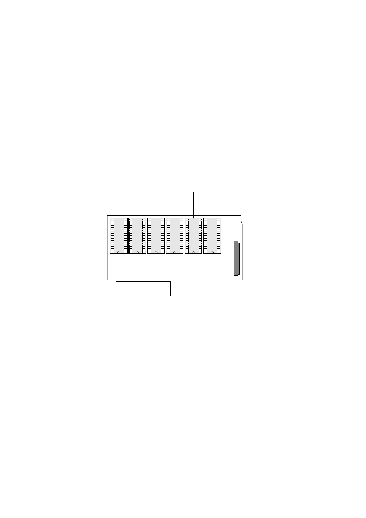
However, if you are using the EPROM board, you must mount two 4-Mbit EPROMs
because this machine uses an 8-Mbit EPROM on the FCE.
NOTE:
The Flash/SRAM data copy board which is used in common with the ADAM and
LFO (P/N: A1939351) must be used for this procedure.
4M bit
(#1)
ROM BOARD II
4M bit
EPROM
(#2)
CN2
EPROM
(0H) U1 (1H) U2 (0L) U3 (1L) U4 U5 (L) U6 (H)
Data Copy Board P/N: A1939351
Mount the 4-Mbit EPROM #1 in the ROM socket U5 (L) and the 4-Mbit EPROM # 2 in the
ROM socket U6 (H) as shown.
It is not necessary to change the jumper at TB1 on the FCU or change system bit switch
02 bit 5 for this machine.
12

4.2. BIT SWITCHES
RAM Reset Level 1:
The address for RAM reset level 1 has been changed to 800005(H).
Change the data to FF(H), then turn the machine off and on to reset all the system
settings.
Communication Parameters
Mode DCS: ITU-T standar d NSS: Non-standard G3
Modem rate 336: 33,600 bps 168: 16,800 bps
312: 31,200 bps 144: 14,400 bps
288: 28,800 bps 120: 12,000 bps
264: 26,400 bps 96: 9,600 bps
240: 24,000 bps 72: 7,200 bps
216: 21,600 bps 48: 4,800 bps
192: 19,200 bps 24: 2,400 bps
TECHNICAL BULLETIN
Communication mode ECM: Wit h ECM SSC: Using SSC
NML: With no ECM or SSC
Compression mode MMR: MMR compression
MR: MR compression
MH: MH compression
Resolution SSF: Fine, transm it t ed at 8 x 15.4 dot s per mm
DTL: Detail, transmitt ed at 8 x 7.7 dot s per mm
STD: Standard, transmit t ed at 8 x 3.85 dot s per mm
I/O rate 0M: 0 ms/line 10M: 10 ms/line
2/M: 2.5 ms/line 20M: 20 ms/line
5M: 5 ms/line 40M: 40 ms/line
Width and reduct ion =A4: A4 (8.3"), no reduction
=B4: B4 (10.1") no reduction
A4: Reduced to A4 (8.3") befor e transmission
System Switch 02
No FUNCTION COMMENTS
Not used Do not change the settings.
5
System Switch 06
No FUNCTION COMMENTS
PC Fax Expander Function
5
0: Disabled 1: Enabled
1: Set this bit to 1 when the PC Fax Expander option
has been installed.
13

System Switch 10
No FUNCTION COMMENTS
Threshold memory level of
0
parallel memory transmission
to
7
System Switch 11
No FUNCTION COMMENTS
Conditions for memory
6
reception if no RTI or CSI is
received
0: Allow memory reception
only when RTI or CSI is
received
1: Allow memory reception
only when RTI or CSI is
received and a printer
(mechanical) error has
occurred
TECHNICAL BULLETIN
Threshold memory = N × 64 kbytes + 256 kbytes
N can be between 00 - FF(H)
Default setting: 04(H) = 512 kbyte
This switch functions in combination with user
parameter switch 05 bit 1.
User parameter switch 05 bit 1 must be set to 1 t o
enable this switch.
User parameter switch 05 bit 1:
Switch to allow memory reception if no RTI or CSI is
received.
0: Allow memory reception for all comm unications
1: Reject if RTI or CSI is not received
System Switch 17
No FUNCTION COMMENTS
Dialing without inserting a
6
document
0: Disabled
1: Enabled
Printer Switch 02
No FUNCTION COMMENTS
Paper Feed Priority
0
0:
Optional paper feed unit >>
100-sheet cassette >>
Standard cassette
1:
Optional paper feed unit >>
Standard cassette >> 100sheet cassette
Communication Swit ch 01
No FUNCTION COMMENTS
Not used Do not change the settings.
1
0: Dialing cannot be done without inserting a
document in the ADF.
This bit determines which set of priorities t he
machine uses for feeding t he paper when all the
cassettes contain the same paper size.
14

Communication Swit ch 17
No FUNCTION COMMENTS
Selective Polling Reception
0
0: Disabled
1: Enabled
Subaddress function (RX)
1
0: Disabled
1: Enabled
G3 Switch 03
No FUNCTION COMMENTS
Use of V.8 protocol
2
0: Disabled
1: Enabled
TECHNICAL BULLETIN
1: Selective polling reception (SEP) is disabled.
1: Subaddress reception is disabled.
1: V.8 protocol is disabled.
15

G3 Switch 05
FUNCTION COMMENTS
Initial Tx modem rat e
0
Bit 3 2 1 0 Setting (bps)
to
0 0 0 1 2.4k
3
0 0 1 0 4.8k
0 0 1 1 7.2k
0 1 0 0 9.6k
0 1 0 1 12.0k
0 1 1 0 14.4k
0 1 1 1 16.8k
1 0 0 0 19.2k
1 0 0 1 21.6k
1 0 1 0 24.0k
1 0 1 1 26.4k
1 1 0 0 28.8k
1 1 0 1 31.2k
1 1 1 0 33.6k
Other settings - Not used
Initial modem type for 9. 6k or
4
7.2kbps (transmission)
to
Bit 5 Bit 4 Setting
5
0 0 V.29
0 1 V.17
1 0 Not used
1 1 Not used
TECHNICAL BULLETIN
These bits set the initial start ing m odem rate for
transmission.
Use the dedicated transmission parameters if you
need to change this for specif ic receivers.
These bits set the initial modem t ype for 9.6k and
7.2kbps, if the init ial modem rate is set at these
speeds.
G3 Switch 06
FUNCTION COMMENTS
Initial Rx modem rate
0
Bit 3 2 1 0 Setting (bps)
to
0 0 0 1 2.4k
3
0 0 1 0 4.8k
0 0 1 1 7.2k
0 1 0 0 9.6k
0 1 0 1 12.0k
0 1 1 0 14.4k
0 1 1 1 16.8k
1 0 0 0 19.2k
1 0 0 1 21.6k
1 0 1 0 24.0k
1 0 1 1 26.4k
1 1 0 0 28.8k
1 1 0 1 31.2k
1 1 1 0 33.6k
Other settings - Not used
The setting of these bit s is used t o inform the
transmitting terminal of the available modem rate for
the machine in receive mode.
Use a lower setting if high speeds pose problems
during reception.
16

TECHNICAL BULLETIN
Modem types available for
4
reception
to
Bit 7 6 5 4 Setting
7
0 0 0 1 V.27ter
0 0 1 0 V.27ter, V.29
0 0 1 1 Not used
0 1 0 0 V.27ter, V.29,
V.17,
0 1 0 1 V.27ter, V.29,
V.17, V.34
Other settings - Not used
The setting of these bit s is used t o inform the
transmitting terminal of the available modem type for
the machine in receive mode.
17

4.5. SERVICE RAM ADDRESSES
The complete RAM addresses are listed because there are too many changes from the
FX6.
800005(H) - RAM Reset Level 1
Change the data at this address to FF (H), then switch the machine off and on to reset all
the system settings.
Caution:
Parameter List).
800001 to 800004(H) - ROM version (Read only)
800001(H) - Revision number (BCD)
800002(H) - Year (BCD)
800003(H) - Month (BCD)
800004(H) - Day (BCD)
Before using this RAM, print the settings of all the system parameters (System
TECHNICAL BULLETIN
800006 to 800016(H)
800018(H)
800019(H)
80001A(H)
80001B(H)
80001C(H)
80001D(H)
80001E(H)
800020 to 80003F(H)
800040 to 80004F(H)
800050 to 80005F(H)
800060 to 80007F(H)
800080 to 80008F(H)
8000A0(H) - User parameter switch 00
Bit 0: Stamp home position 0: Disabled, 1: Enabled
Bits 1 and 2: Scanning contrast home position
Bit 2 1 Setting
0 0 Normal
0 1 Lighten
1 0 Darken
Bit 3: Do not adjust
Bits 4 and 5: Scanning resolution home position
Bit 5 4 Setting
0 0 Standard
0 1 Detail
1 0 Fine
Bit 6: Transmission mode home position 0: Memory tx, 1: Immediate tx
Bit 7: Halftone home position 0: Disabled, 1: Enabled
- Total program checksum (low)
- Total program checksum (high)
- Boot program checksum (low)
- Boot program checksum (high)
- Main program checksum (low)
- Main program checksum (high)
- RDS program update counter (hex)
- Machine's serial number (17 digits - ASCII)
- System bit switches
- Scanner bit switches
- Printer bit switches
- Communication bit switches
- G3 bit switches
18

8000A1(H) - User parameter switch 01
Bits 0 to 6: Not used
Bit 7: Settings return to home position after transmission 0: Disabled , 1: Enabled
8000A2(H) - User parameter switch 02
Bit 0: Forwarding mark printing on forwarded messages 0: Disabled, 1: Enabled
Bit 1: Center mark printing on received copies 0: Disabled, 1: Enabled
Bit 2: Reception time printing 0: Disabled, 1: Enabled
Bit 3: TSI included in transmitted messages 0: Disabled, 1: Enabled
Bit 4: Checkered mark printing 0: Disabled, 1: Enabled
Bits 5 to 7: Not used
TECHNICAL BULLETIN
8000A3(H) - User parameter switch 03
Bit 0: Transmission result report (memory transmissions) 0: Off, 1: On
Bit 1: Not used
Bit 2: Memory storage report 0: Off, 1: On
Bit 3: Polling reserve report (polling reception) 0: Off, 1: On
Bit 4: Polling result report (polling reception) 0: Off, 1: On
Bit 5: Transmission result report (immediate transmissions) 0: Off, 1: On
Bit 6: Polling clear report 0: Off, 1: On
Bit 7: TCR (Journal) 0: Off, 1: On
8000A4(H) - User parameter switch 04
Bit 0: Automatic confidential reception report output 0: Off, 1: On
Bits 1 to 6: Not used
Bit 7: Inclusion of a sample image on reports 0: Off, 1: On
8000A5(H) - User parameter switch 05
Bit 0: Substitute reception 0: Off, 1: On
Bit 1: Memory reception if no RTI or CSI received 0: Possible, 1: Impossible
Bits 2 and 3: Not used
Bit 4: Restricted Access 0: Off, 1: On
Bit 5: Not used (keep this bit at 0.)
Bit 6: Fusing lamp control during energy saver mode
0: Lamp off, 1: Standby temperature (80 °C)
Bit 7: Not used (keep this bit at 0.)
(Automatic report printout)
8000A6(H) - User parameter switch 06
Bit 0: TTI 0: Off, 1: On
Bit 1: Not used
Bit 2: Closed network for transmission 0: Off, 1: On
Bit 3: Not used
Bit 4: Batch transmission 0: Off, 1: On
Bits 5 to 7: Not used
19

8000A7(H) - User parameter switch 07
Bits 0 to 2: Not used
Bit 3: Automatic reduction (B4 ->> A4) before transmission 0: Off, 1: On
Bits 4 to 7: Not used
8000A8(H) - User parameter switch 08
Bit 0 and 1: Multi-copy reception
Bit 1 0 Setting
X 0 Disabled
0 1 Faxes from senders whose RTIs/CSIs are specified for this
feature are multi-copied.
1 1 Faxes from senders whose RTIs/CSIs are not specified for
this feature are multicopied.
Bits 2 and 3: Authorized reception
Bit 3 2 Setting
X 0 Disabled
0 1 Faxes from senders whose RTIs/CSIs are specified for this
feature are accepted.
1 1 Faxes from senders whose RTIs/CSIs are not specified for
this feature are accepted.
Bits 4 and 5: Specified cassette selection (optional PFU required)
Bit 3 2 Setting
X 0 Disabled
0 1 Faxes from senders whose RTIs/CSIs are specified for this
feature are printed to the paper in a specified cassette.
1 1 Faxes from senders whose RTIs/CSIs are not specified for
this feature are printed to the paper in a specified cassette.
Bits 6 and 7: Forwarding
Bit 1 0 Setting
X 0 Disabled
0 1 Faxes from senders whose RTIs/CSIs are specified for this
feature are forwarded.
1 1 Faxes from senders whose RTIs/CSIs are not specified for
this feature are forwarded.
TECHNICAL BULLETIN
8000A9(H) - User parameter switch 09
Bits 0 and 1: Memory lock (optional memory card required)
Bit 1 0 Setting
X 0 Disabled
0 1 Faxes from senders whose RTIs/CSIs are specified are kept
in the memory until a memory lock ID is entered.
1 1 Faxes from senders whose RTIs/CSIs are not specified are
kept in the memory until a memory lock ID is entered.
Bits 2 to 7: Not used
20

8000AA(H) - User parameter switch 10
Bit 0: Reverse order printing 0: Disabled, 1: Enabled
Bit 1: Two in 1 (printing two Half-letter (A5) messages onto one Letter (A4) paper)
Bits 2 to 6: Not used
Bit 7: Halftone type 0: Error diffusion, 1: Dither
8000AB(H) - User parameter switch 11
Bits 0 to 5: Not used
Bit 6: Printout of messages received while acting as a forwarding station
Bit 7: Polling Standby duration 0: Once, 1: No limit
8000AC(H) - User parameter switch 12
Bits 0 and 1: Not used
Bit 2: Toner saving mode 0: Disabled, 1: Enabled
Bits 3 and 4: Printout image density (Fax mode)
Bit 4 3 Setting
0 0 Normal
0 1 Lighten
1 0 Darken
1 1 Not used
Bits 5 to 7: Not used
TECHNICAL BULLETIN
0: Disabled, 1: Enabled
0: Off, 1: On
8000AD(H) - User parameter switch 13
Bits 0 and 1: PSTN access method from behind PABX
Bit 1 0 Setting
0 0 PSTN
0 1 Loop start
1 0 Ground start
1 1 Flash start
Bits 2 to 7: Not used
8000AE - 8000AF(H) - User parameter 14 to 15
Not used
8000B9(H) - User function 62 settings
Bit 0: Night timer 0: Disabled, 1: Enabled
Bits 1 to 3: Not used
Bit 4: RDS operation 0: Not acceptable
1: Acceptable for the limit specified by system switch 03
Bits 5 and 6: Not used
Bit 7: Daylight saving time 0: Disabled, 1: Enabled
8000BA(H) - User function 62 settings
Bit 0: Not used
Bit 1: Dialing type 0: Pulse dialing (10 pps), 1: Tone (DTMF) dialing
Bits 2 to 7: Not used
21

8000BB(H) - PSTN access number for loop start
Access number Hex value to program (BCD)
0 F0
ØØ
0 F0
00 00
ØØ
99 99
8000C8 to 8000DB(H) - RTI (Max. 20 characters - ASCII) - Note 1
8000DC to 8000EF(H) - CSI (Max. 20 characters - ASCII)
8000F0 to 80010F(H) - TTI (Max. 32 characters - ASCII) - Note 1
800110(H) - Number of CSI characters (Hex)
Note 1: If the number of characters are less than the maximum (20 for RTI, 32 for TTI),
add a stop code (FF[H]) after the last character.
800111 to 80011F(H) - Service station's fax number (Service function 13)
800120 to 80012E(H) - Own fax number (User function 61)
80012F(H) - ID code (low - Hex)
800130(H) - ID code (high - Hex)
TECHNICAL BULLETIN
800131(H) - Confidential ID (low - BCD)
800132(H) - Confidential ID (high - BCD)
800133(H) - Memory lock ID (low - Hex)
800134(H) - Memory lock ID (high - Hex)
800140 to 800146(H) - Last power off time (Read only)
800140(H) - Year (BCD)
800141(H) - Month (BCD)
800142(H) - Day (BCD)
800143(H) - 00: Monday, 01: Tuesday, 02: Wednesday, ....... , 06: Sunday
800144(H) - Hour
800145(H) - Minute
800146(H) - Second
800150(H) - Optional equipment (Read only)
Bit 0: Memory card 0: Not installed, 1: Installed
Bit 1-3: Not used
Bit 4: 100-sheet cassette 0: Not installed, 1: Installed
Bit 5: Paper feed unit 0: Not installed, 1: Installed
Bit 6-7: Not used
800151(H) - Optional equipment (Read only)
Bit 0: Not used
Bit 1: Printer interface 0: Not installed, 1: Installed
Bit 2-7: Not used.
22

The following counters are listed on the System Parameter List. The names used on the
system parameter list are given in brackets
TECHNICAL BULLETIN
800158 to 80015A(H)
Address High Low
800158(H) Tens digit Unit digit
800159(H) Thousands digit Hundreds digit
80015A(H) Millions digit Ten thousands digit
Note:
80015B to 80015D(H)
80015E to 800160(H)
800161 to 800163(H)
800164 to 800166(H)
800167 to 800169(H)
80016A to 80016C(H)
80016D to 80016F(H)
800170 to 800172(H)
800176 to 800178(H)
The following counters have the same data format as above.
- Tx counter (TX)
- Rx counter (RX)
- Scan counter (SCN)
- Print counter (PRT)
- Printer interface output counter (PRN)
- Paper feed counter: standard cassette (UPPER CASSETTE)
- Paper feed counter: optional PFU (CASSETTE 2)
- Paper feed counter: optional 100-sheet cassette
- Paper feed counter: bypass feed (BY-PASS)
- ADF counter (ADF)
80017C to 80017E(H)
80017F to 800181(H)
800182 to 800184(H)
800185 to 800187(H)
800188 to 80018A(H)
80018B to 80018D(H)
80018E to 800190(H)
800191 to 800193(H)
800197 to 800199(H)
80019A to 80019C(H)
80019D to 80019F(H)
8001A0 to 8001A2(H)
8001A3 to 8001A5(H)
The machine asks the user to replace the drum at this interval, if bit 3 of system bit switch
04 is 0.
8001A6 to 8001A8(H)
- Printer total jam counter (COPY JAM)
- Paper jam counter: standard cassette (UPPER CST JAM)
- Paper jam counter: optional PFU (CST 2 JAM)
- Paper jam counter: optional 100-sheet cassette (OPEN CST JAM)
- Paper jam counter: bypass feed (BY-PASS)
- Scanner total jam counter (DOC. JAM)
- Fusing exit jam counter (EJECT JAM)
- Registration jam counter (PAPER JAM)
- PM counter (PM)
- PM call interval: default 60,000 (PM DEFAULT)
- Copy counter (COPY)
- OPC (master drum) counter (PCU)
- OPC (master drum) replacement interval (default: 30,000 prints)
- CTM counter (TONER)
8001ED to 8001FC(H)
800200(H)
- Number of copies in multi-sort document reception (User function 83)
- Excessive jam call parameters
23

800201 to 80022A(H) - Night timer period (User function 71)
800201 to 800203(H) - Setting #1 for Monday
800204 to 800206(H) - Setting #2 for Monday
800207 to 800209(H) - Setting #1 for Tuesday
80020A to 80020C(H) - Setting #2 for Tuesday
80020D to 80020F(H) - Setting #1 for Wednesday
800210 to 800212(H) - Setting #2 for Wednesday
800213 to 800215(H) - Setting #1 for Thursday
800216 to 800218(H) - Setting #2 for Thursday
800219 to 80021B(H) - Setting #1 for Friday
80021C to 80021E(H) - Setting #2 for Friday
80021F to 800221(H) - Setting #1 for Saturday
800222 to 800224(H) - Setting #2 for Saturday
800225 to 800227(H) - Setting #1 for Sunday
800228 to 80022A(H) - Setting #2 for Sunday
Program format
First byte - Hour (BCD)
Second byte - Minute (BCD)
Third byte - 00(H): Timer start time, 01(H): Timer end time
TECHNICAL BULLETIN
800255 to 80025B(H) - Last RDS operation (Read only)
800255(H) - Year (BCD)
800256(H) - Month (BCD)
800257(H) - Day (BCD)
800258(H) - 00: Monday, 01: Tuesday, 02: Wednesday, ....... , 06: Sunday
800259(H) - Hour
80025A(H) - Minute
80025B(H) - Second
80025D(H)
800260(H)
800261(H)
800262(H)
800264(H)
800265(H)
800266 to 80026A(H)
800271 to 800273(H)
8002B4 to 8002B5(H)
8002B6 to 8002B7 (H)
- Daylight saving time setting (User function 62)
- Transmission monitor volume 00 - 07(H)
- Reception monitor volume 00 - 07(H)
- On-hook monitor volume 00 - 07(H)
- Buzzer volume 00 - 07(H)
- Key acknowledgment tone volume00 - 07(H)
- Periodic service call parameters
- Effective term of automatic service calls
- Scanning top margin adjustment
- Scanning bottom margin adjustment
24

80036F(H) - Details of the service call (hardware error)
01(H) - The fusing lamp temperature stayed above 175 °C while printing.
02(H) - The fusing lamp temperature did not reach 150 °C before starting printing.
03(H) - The fusing lamp temperature did not go down to 100 °C while in standby mode
(when fusing lamp OFF was selected for power saver mode)
04(H) - The fusing lamp temperature did not go down to 100 °C while in standby mode
(when fusing lamp Standby (100 °C) was selected for power saver mode)
05(H) - The fusing lamp temperature stayed below 100 °C while in standby mode (when
fusing lamp Standby (100 °C) was selected for power saver mode)
07(H) - The fusing lamp temperature came below 140 °C while printing
08(H) - The fusing lamp temperature exceeded 250 °C
09(H) - A fusing thermistor error was detected
TECHNICAL BULLETIN
NOTE:
800370(H) - Excessive jam alarm
Bit 3: Scanner excessive jam alarm 1: An alarm has occurred
Bit 4: Printer excessive jam alarm 1: An alarm has occurred
NOTE:
800371(H) - Details of the service call (hardware error)
01(H) - The fusing lamp temperature stayed above 175 °C while printing.
02(H) - The fusing lamp temperature did not reach 150 °C before starting printing.
03(H) - The fusing lamp temperature did not go down to 100 °C while in standby mode
(when fusing lamp OFF was selected for power saver mode)
04(H) - The fusing lamp temperature did not go down to 100 °C while in standby mode
(when fusing lamp Standby (100 °C) was selected for power saver mode)
05(H) - The fusing lamp temperature stayed below 100 °C while in standby mode (when
fusing lamp Standby (100 °C) was selected for power saver mode)
07(H) - The fusing lamp temperature came below 140 °C while printing
08(H) - The fusing lamp temperature exceeded 250 °C
09(H) - A fusing thermistor error was detected
11(H) - Charge leak current was detected while the charge corona unit was activated
12(H) - Charge leak current was detected while the charge corona unit was not activated
21(H) - The laser synchronization signal was not detected during printing
31(H) - Polygonal mirror motor startup error
32(H) - Polygonal mirror motor error during printing
41(H) - Main motor startup error
42(H) - Main motor erro r during printing
When a service call was caused by a fusing unit failure (codes 01 - 09):
After fixing the problem, reset the data at this address to 00(H), then restart the
machine to clear the service call. (Refer to address 800371(H) for other hardware
failures.)
Either or both of these bits will change to 1 when an excessive jam alarm occurs.
Reset each bit to 0 when you have solved the problem. The machine will not be
able to detect excessive jams in future if you do not reset these bits.
25
 Loading...