

Ricoh FAX2700L SPECIFICATIONS fx4800

FR4
RICOH FAX4800L
SERVICE MANUAL
July 6th, 1998
Subject to change

Important Safety Notices
H551r501.WMF
Laser Safety
WARNING FOR LASER UNIT
I
This machine contains a laser beam generator. Laser beams can cause
permanent eye damage. Do not open the laser unit or look along the laser
beam path while the main power is on.
Lithium Batteries (Memory Back-up)
CAUTION
I
The danger of explosion exists if a battery of this type is incorrectly
replaced.
Replace only with the same or an equivalent type recommended by the
manufacturer. Discard used batteries in accordance with the
manufacturer's instructions.
July 6th, 1998 SPECIFICATIONS
1. OVERALL MACHINE INFORMATION
1.1 SPECIFICATIONS
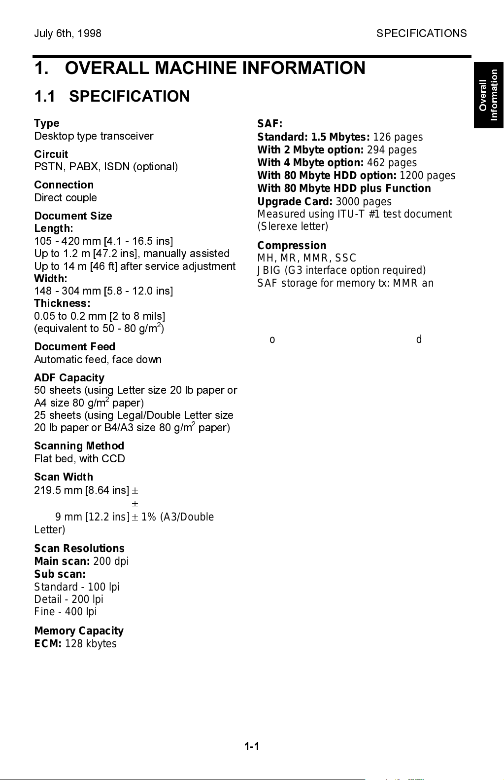
Type
Desktop type transceiver
Circuit
PSTN, PABX, ISDN (optional)
Connection
Direct couple
Document Size
Length:
105 - 420 mm [4.1 - 16.5 ins]
Up to 1.2 m [47.2 ins], manually assisted
Up to 14 m [46 ft] after service adjustment
Width:
148 - 304 mm [5.8 - 12.0 ins]
Thickness:
0.05 to 0.2 mm [2 to 8 mils]
(equivalent to 50 - 80 g/m
Document Feed
Automatic feed, face down
ADF Capacity
50 sheets (using Letter size 20 lb paper or
A4 size 80 g/m
2
paper)
25 sheets (using Legal/Double Letter size
20 lb paper or B4/A3 size 80 g/m
Scanning Method
Flat bed, with CCD
Scan Width
219.5 mm [8.64 ins]
260.1 mm [10.2 ins] ± 1% (B4)
308.9 mm [12.2 ins] ± 1% (A3/Double
Letter)
Scan Resolutions
Main scan: 200 dpi
Sub scan:
Standard - 100 lpi
Detail - 200 lpi
Fine - 400 lpi
Memory Capacity
ECM: 128 kbytes
2
)
±
1% (A4/Letter)
2
paper)
SAF:
Standard: 1.5 Mbytes: 126 pages
With 2 Mbyte option: 294 pages
With 4 Mbyte option: 462 pages
With 80 Mbyte HDD option: 1200 pages
With 80 Mbyte HDD plus Function
Upgrade Card: 3000 pages
Measured using ITU-T #1 test document
(Slerexe letter)
Compression
MH, MR, MMR, SSC
JBIG (G3 interface option required)
SAF storage for memory tx: MMR and raw
data
Protocol
Group 3 with ECM
Group 4 (ISDN G4 option required)
Modulation
V.34 (TCM), V.33/V.17(TCM), V.29 (QAM),
V.27ter (PHM), V.21 (FM)
Data Rate (bps)
G3:
33600/31200/28800/26400/24000/21600/
19200/16800/14400/12000/9600/7200/
4800/2400
G4 (option): 64 kbps/56 kbps
I/O Rate
With ECM: 0 ms/line
Without ECM: 2.5, 5, 10, 20, or 40 ms/line
Transmission Time
G3: 3 s at 28800 bps;
Measured with G3 ECM using memory for
an ITU-T #1 test document (Slerexe letter)
at standard resolution
G4 (option): 3 s at 64 kbps;
Measured with an ITU-T #1 test document
(Slerexe letter) at standard resolution
Printing System
Laser printing, plain paper, dry toner
Overall
Information
1-1

SPECIFICATIONS July 6th, 1998
Paper Size and Capacity
Standard Cassette: 250 sheets
USA: Letter, Legal
Europe: A4, A5 sideways
Asia: A4, A5 sideways, F/F4
100 Sheet Cassette (Optional): 100
sheets
USA: Letter, Legal
Europe: A4, A5 sideways
Asia: A4, A5 sideways, F, F4
Paper Feed Unit (Optional): 500 sheets
USA: Letter, Legal
Europe: A4, A5 sideways
Asia: A4, A5 sideways, F/F4
Note: Up to two PFUs can be installed.
Maximum Printing Width
208 mm [8.2 ins] (Letter)
202 mm [8.0 ins] (A4)
Print Resolutions
Fax and Copy Mode:
Main scan: 400 dpi
Sub scan: 400 dpi
Printer Mode: 300 x 300 dpi
Weight
Approx. 19 kg [50.9 lbs]
Excluding CTM, handset, trays, and
optional units
Power Supply
USA: 115 ± 20 Vac, 50 ± 1 Hz
Europe/Asia: 187 - 276 Vac, 60 ± 1 Hz
Power Consumption (Base Machine
Only)
Standby:
Minimum 2 W (see Note)
Normal 30 W
Transmitting: 60 W
Receiving: 220 W (Maximum: 900 W)
Copying: 300 W (Maximum: 950 W)
Note: 2W mode is not available if one of the
following options is installed.
- Printer interface unit
- G4
- RS232C interface
Operating Environment
Temperature: 17 - 28°C [63 - 82°F]
Humidity: 40 - 70 %Rh
Dimensions (W x D x H)
475 x 520 x 260 mm [18.7 x 20.5 x 10.2 ins]
Excluding handset, trays, and optional units
1-2
July 6th, 1998 FEATURES
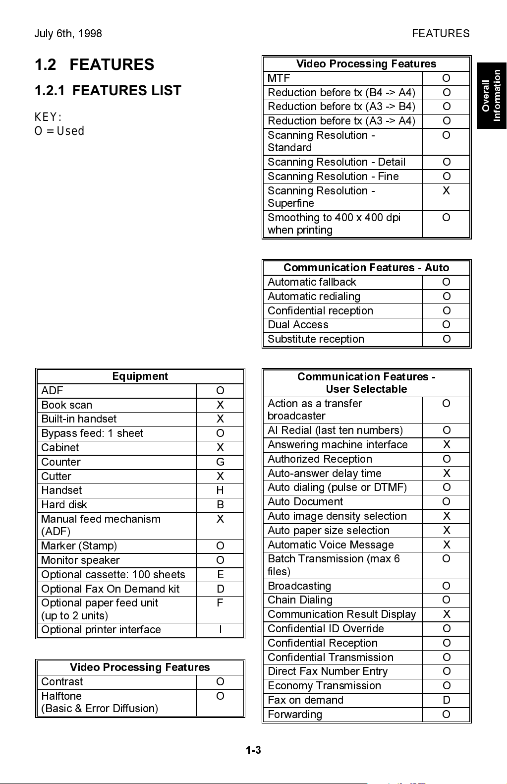
1.2 FEATURES
1.2.1 FEATURES LIST
KEY:
O = Used, X = Not Used,
A = With optional memory 2M/4M only
B = With optional memory 80M (HDD)
only
C = With optional function upgrade
card only
D = With optional Fax On Demand kit
only
E = With optional 100 sheet cassette
only
F = With optional paper feed unit only
G= With optional counter only
H = With optional handset only (US
only)
I = With optional printer interface unit
only
J = With optional G4 kit only
Video Processing Features
MTF O
Reduction before tx (B4 -> A4) O
Reduction before tx (A3 -> B4) O
Reduction before tx (A3 -> A4) O
Scanning Resolution -
Standard
Scanning Resolution - Detail O
Scanning Resolution - Fine O
Scanning Resolution -
Superfine
Smoothing to 400 x 400 dpi
when printing
Communication Features - Auto
Automatic fallback O
Automatic redialing O
Confidential reception O
Dual Access O
Substitute reception O
O
X
O
Overall
Information
Equipment
ADF O
Book scan X
Built-in handset X
Bypass feed: 1 sheet O
Cabinet X
Counter G
Cutter X
Handset H
Hard disk B
Manual feed mechanism
(ADF)
Marker (Stamp) O
Monitor speaker O
Optional cassette: 100 sheets E
Optional Fax On Demand kit D
Optional paper feed unit
(up to 2 units)
Optional printer interface I
Video Processing Features
Contrast O
Halftone
(Basic & Error Diffusion)
X
F
O
Communication Features -
User Selectable
Action as a transfer
broadcaster
AI Redial (last ten numbers) O
Answering machine interface X
Authorized Reception O
Auto-answer delay time X
Auto dialing (pulse or DTMF) O
Auto Document O
Auto image density selection X
Auto paper size selection X
Automatic Voice Message X
Batch Transmission (max 6
files)
Broadcasting O
Chain Dialing O
Communication Result Display X
Confidential ID Override O
Confidential Reception O
Confidential Transmission O
Direct Fax Number Entry O
Economy Transmission O
Fax on demand D
Forwarding O
O
O
1-3
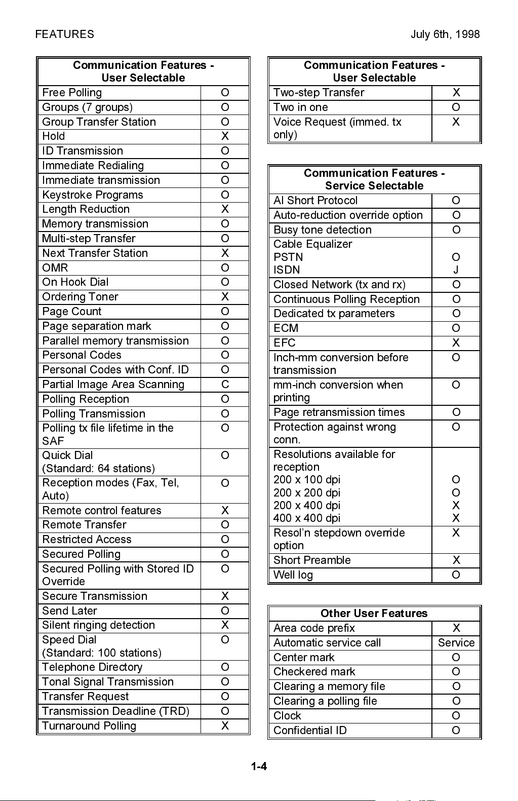
FEATURES July 6th, 1998
Communication Features -
User Selectable
Free Polling O
Groups (7 groups) O
Group Transfer Station O
Hold X
ID Transmission O
Immediate Redialing O
Immediate transmission O
Keystroke Programs O
Length Reduction X
Memory transmission O
Multi-step Transfer O
Next Transfer Station X
OMR O
On Hook Dial O
Ordering Toner X
Page Count O
Page separation mark O
Parallel memory transmission O
Personal Codes O
Personal Codes with Conf. ID O
Partial Image Area Scanning C
Polling Reception O
Polling Transmission O
Polling tx file lifetime in the
O
SAF
Quick Dial
O
(Standard: 64 stations)
Reception modes (Fax, Tel,
O
Auto)
Remote control features X
Remote Transfer O
Restricted Access O
Secured Polling O
Secured Polling with Stored ID
O
Override
Secure Transmission X
Send Later O
Silent ringing detection X
Speed Dial
O
(Standard: 100 stations)
Telephone Directory O
Tonal Signal Transmission O
Transfer Request O
Transmission Deadline (TRD) O
Turnaround Polling X
Communication Features -
User Selectable
Two-step Transfer X
Two in one O
Voice Request (immed. tx
X
only)
Communication Features -
Service Selectable
AI Short Protocol O
Auto-reduction override option O
Busy tone detection O
Cable Equalizer
PSTN
ISDN
O
J
Closed Network (tx and rx) O
Continuous Polling Reception O
Dedicated tx parameters O
ECM O
EFC X
Inch-mm conversion before
O
transmission
mm-inch conversion when
O
printing
Page retransmission times O
Protection against wrong
O
conn.
Resolutions available for
reception
200 x 100 dpi
200 x 200 dpi
200 x 400 dpi
400 x 400 dpi
Resoln stepdown override
O
O
X
X
X
option
Short Preamble X
Well log O
Other User Features
Area code prefix X
Automatic service call Service
Center mark O
Checkered mark O
Clearing a memory file O
Clearing a polling file O
Clock O
Confidential ID O
1-4
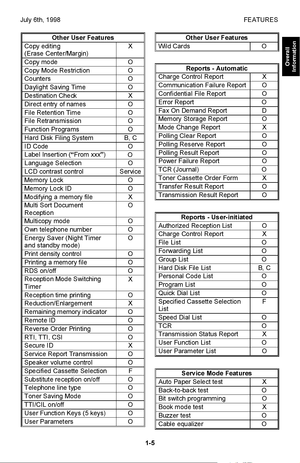
July 6th, 1998 FEATURES
Other User Features
Copy editing
X
(Erase Center/Margin)
Copy mode O
Copy Mode Restriction O
Counters O
Daylight Saving Time O
Destination Check X
Direct entry of names O
File Retention Time O
File Retransmission O
Function Programs O
Hard Disk Filing System B, C
ID Code O
Label Insertion (From xxx)
O
Language Selection O
LCD contrast control Service
Memory Lock O
Memory Lock ID O
Modifying a memory file X
Multi Sort Document
O
Reception
Multicopy mode O
Own telephone number O
Energy Saver (Night Timer
O
and standby mode)
Print density control O
Printing a memory file O
RDS on/off O
Reception Mode Switching
X
Timer
Reception time printing O
Reduction/Enlargement X
Remaining memory indicator O
Remote ID O
Reverse Order Printing O
RTI, TTI, CSI O
Secure ID X
Service Report Transmission O
Speaker volume control O
Specified Cassette Selection F
Substitute reception on/off O
Telephone line type O
Toner Saving Mode O
TTI/CIL on/off O
User Function Keys (5 keys) O
User Parameters O
Other User Features
Wild Cards O
Reports - Automatic
Charge Control Report X
Communication Failure Report O
Confidential File Report O
Error Report O
Fax On Demand Report D
Memory Storage Report O
Mode Change Report X
Polling Clear Report O
Polling Reserve Report O
Polling Result Report O
Power Failure Report O
TCR (Journal) O
Toner Cassette Order Form X
Transfer Result Report O
Transmission Result Report O
Reports - User-initiated
Authorized Reception List O
Charge Control Report X
File List O
Forwarding List O
Group List O
Hard Disk File List B, C
Personal Code List O
Program List O
Quick Dial List O
Specified Cassette Selection
F
List
Speed Dial List O
TCR O
Transmission Status Report X
User Function List O
User Parameter List O
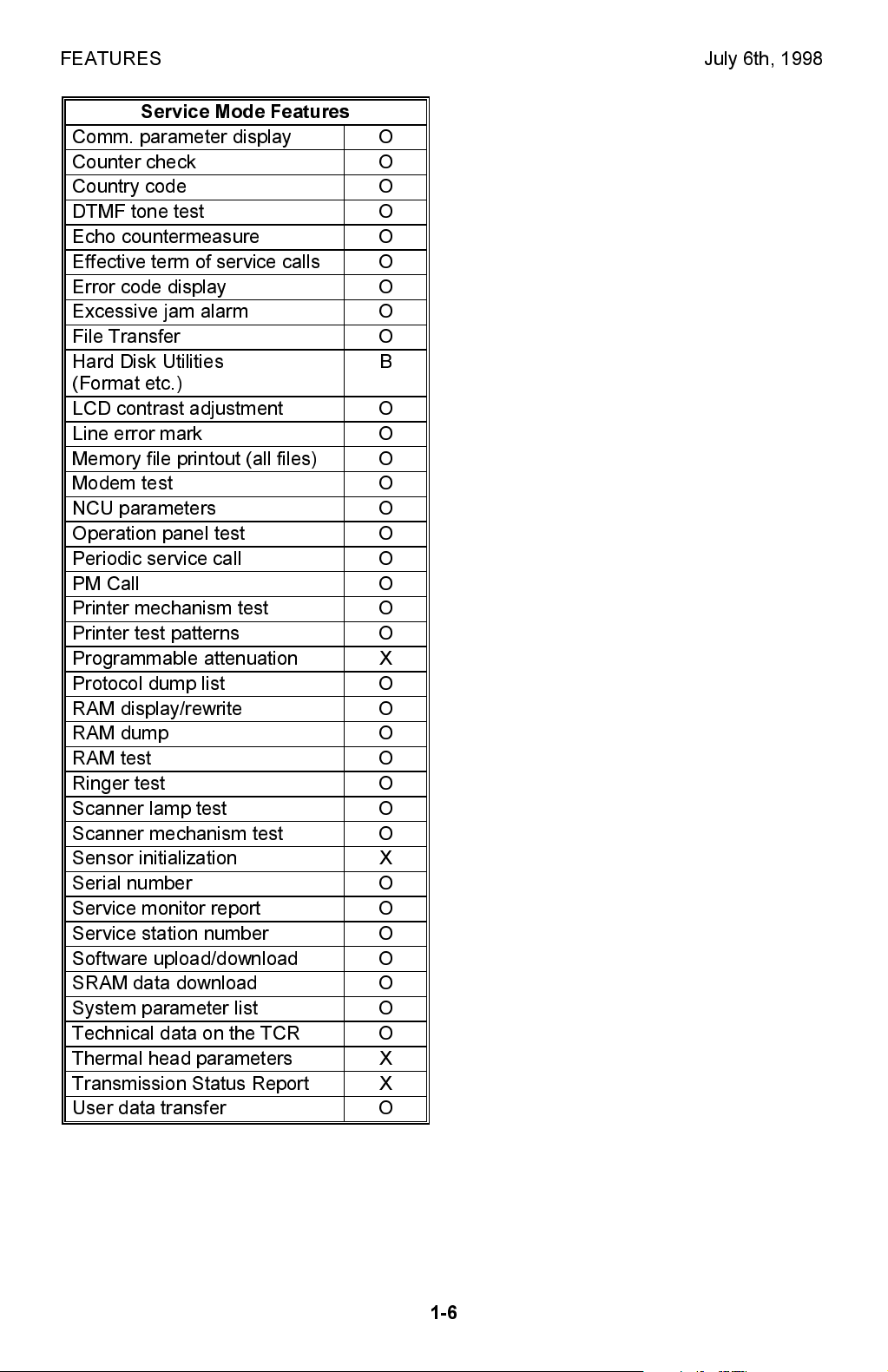
Service Mode Features
Auto Paper Select test X
Back-to-back test O
Bit switch programming O
Book mode test X
Buzzer test O
Cable equalizer O
Overall
Information
1-5
FEATURES July 6th, 1998
Service Mode Features
Comm. parameter display O
Counter check O
Country code O
DTMF tone test O
Echo countermeasure O
Effective term of service calls O
Error code display O
Excessive jam alarm O
File Transfer O
Hard Disk Utilities
B
(Format etc.)
LCD contrast adjustment O
Line error mark O
Memory file printout (all files) O
Modem test O
NCU parameters O
Operation panel test O
Periodic service call O
PM Call O
Printer mechanism test O
Printer test patterns O
Programmable attenuation X
Protocol dump list O
RAM display/rewrite O
RAM dump O
RAM test O
Ringer test O
Scanner lamp test O
Scanner mechanism test O
Sensor initialization X
Serial number O
Service monitor report O
Service station number O
Software upload/download O
SRAM data download O
System parameter list O
Technical data on the TCR O
Thermal head parameters X
Transmission Status Report X
User data transfer O
1-6

July 6th, 1998 FEATURES
1.2.2 CAPABILITIES OF PROGRAMMABLE ITEMS
The following table shows how the capability of each programmable item changes
after the optional function upgrade card is installed.
Item Standard
Maximum number of memory files plus
polling rx files
Maximum number of memory files 200 1000
Maximum number of destinations per file 200 1000
Maximum number of destinations overall 500 2000
Maximum number of pages overall 1200 3000
Number of Quick Dials 64 64
Number of Speed Dials 100 1000
Number of Groups 9 30
Maximum number of destinations per
Group
Maximum number of destinations dialed
from the ten-key pad overall
Maximum number of programs
(programmed in 64
Quick Dial keys)
Maximum number of destinations per
program
Maximum number of destinations used
for all programs
Maximum number of Auto Documents 64
(programmed in 64
Quick Dial keys)
Maximum number of communication
records for the TCR (Journal) stored in
the memory
Maximum number of addresses specified
for features such as Authorized
Reception and Specified Cassette
Selection
Maximum number of personal codes 50 500
200 1000
200 200
100 1000
64
200 200
300 2000
256 1000
30 50
With function
upgrade card
164
(programmed in 64
Quick Dial keys plus
100 Speed Dial
codes)
164
(programmed in 64
Quick Dial keys plus
100 Speed Dial
codes)
Overall
Information
1-7
FEATURES July 6th, 1998
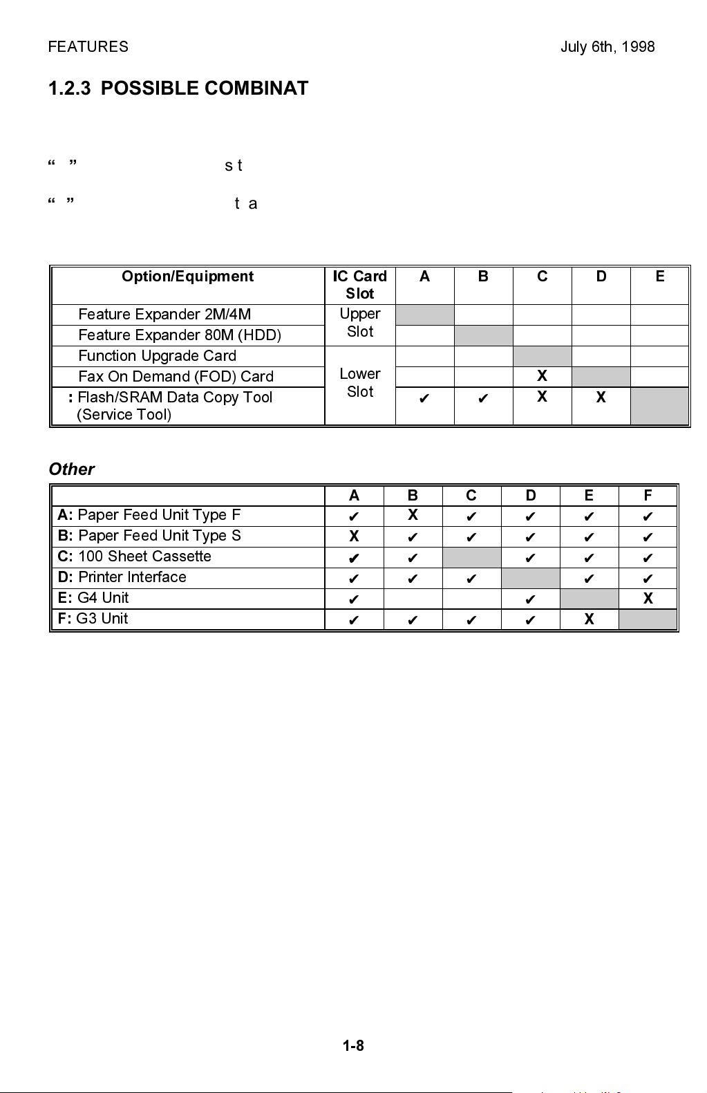
1.2.3 POSSIBLE COMBINATIONS OF OPTIONAL EQUIPMENT
The following table shows which items of optional equipment can be or cannot be
installed at the same time.
✔
in the table indicates that the two items of optional equipment can be installed
at the same time.
X
in the table indicates that the two items of optional equipment cannot be
installed at the same time.
IC Cards
Option/Equipment IC Card
A:
Feature Expander 2M/4M
B:
Feature Expander 80M (HDD)
C:
Function Upgrade Card
D:
Fax On Demand (FOD) Card
E:
Flash/SRAM Data Copy Tool
(Service Tool)
Other
A:
Paper Feed Unit Type F
B:
Paper Feed Unit Type S
C:
100 Sheet Cassette
D:
Printer Interface
E:
G4 Unit
F:
G3 Unit
ABCDE
Slot
Upper
Slot
Lower
Slot
ABCDEF
✔
X
✔ ✔
✔✔✔
✔✔✔✔
✔✔✔✔
X
✔✔
✔✔
✔✔
X
✔✔✔✔✔
X
✔✔✔✔
✔✔✔
✔✔✔
XX
X
X
✔✔✔
X
✔✔
X
X
X
1-8
July 6th, 1998 OVERALL MACHINE CONTROL
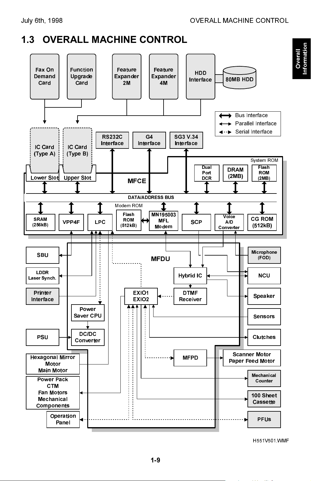
1.3 OVERALL MACHINE CONTROL
Fax On
Demand
Card
IC Card
(Type A)
Lower Slot
SRAM
(256kB)
Function
Upgrade
Card
IC Card
(Type B)
Upper Slot
VPP4F
RS232C
Interface
LPC
Feature
Expander
2M
Interface
MFCE
DATA/ADDRESS BUS
Modem ROM
Flash
ROM
(512kB)
Feature
Expander
4M
G4
MN195003
MFL
Modem
Interface
SG3 V.34
Interface
SCP
HDD
Dual
Port
DCR
80MB HDD
Bus Interface
Parallel Interface
Serial Interface
DRAM
(2MB)
Voice
A/D
Converter
Overall
Information
System ROM
Flash
ROM
(2MB)
CG ROM
(512kB)
SBU
LDDR
Laser Synch.
Printer
Interface
PSU
Hexagonal Mirror
Motor
Main Motor
Power Pack
CTM
Fan Motors
Mechanical
Components
Operation
Panel
Power
Saver CPU
DC/DC
Converter
EXIO1
EXIO2
MFDU
Hybrid IC
DTMF
Receiver
MFPD
Microphone
(FOD)
NCU
Speaker
Sensors
Clutches
Scanner Motor
Paper Feed Motor
Mechanical
Counter
100 Sheet
Cassette
PFUs
1-9
H551V501.WMF

OVERALL MACHINE CONTROL July 6th, 1998
The MFCE contains most of the logical components for overall system control, and
direct interfaces to the IC cards, an RS232C interface, a G4 interface (CiG4-SV)
and a optional G3 interface (SG3-V.34).
The MFDU has interfaces to the power supply, sensors, drive components, and
optional equipment.
The RS232C interface may not be available in some models.
There are two cpus in the machine: the main cpu (SCP) on the MFCE and the
energy saver cpu on the MFDU. In energy saver mode, the main CPU switches off
and the energy saver CPU takes over.
The 2 MB (16Mbit) flash ROM contains the system software, which can be updated
through an IC card slot or from the remote control center using RDS.
The CGROM (Character Generation ROM) contains all the character fonts used on
the display and in reports.
The Panasonic MN195003MFL modem is used for all the communications (V.34,
V.17, V.29, V.27ter., and V.21). The 512kB flash ROM contains the modem
program.
The 2 MB DRAM is used for the SAF memory, ECM buffer memory, work area,
and page memory. The SAF memory can be extended by 2, 4, or 80 MB with an IC
memory card or a hard disk.
The 256 kB SRAM contains the user and system parameters. This can be
upgraded by 512 kB with the function upgrade card. These SRAMs are battery
backed-up.
* The SRAMs in the IC cards are battery backed up, in case the the machine is
turned off or the machine goes into the 2-watt energy saver. However, the data in
these SRAMs are not guaranteed if the card is disconnected from the machine.
Whenever the Fax On Demand card or Function Upgrade Card needs to be
removed for using the service tool, follow the instructions in section 4-1 to avoid
any data loss.
1-10

July 6th, 1998 SEP/SUB CODING
2. DETAILED SECTION DESCRIPTIONS
2.1 SEP/SUB CODING
Overview.
ITU-T introduced the following protocol signals in the T.30 recommendation in
1996. These signals enable confidential transmission and secured polling between
machines produced by different manufacturers.
SEP (Selective Polling): This signal informs the other terminal of the polling ID to
enable secured (ID) polling.
Up to 20 digits or characters can be sent in a SEP frame.
PWD (Password): This signal informs the other terminal of the password to enable
extra security.
Up to 20 digits or characters can be sent in a PWD frame.
SUB (Sub-address): This signal informs a sub-address of a destination. Some fax
servers use this information to route a received fax message to a specific address
in the local network.
Up to 20 digits or characters can be sent in a SUB frame.
Detailed
Descriptions
SID (Sender ID): This signal informs the other terminal of the sender ID to identify
the transmitter.
Up to 20 digits or characters can be sent in a SID frame.
The ITU-T recommendation only clarifies the requirements for the transmitting
terminal, and does not specify the requirements for the receiving terminal. How the
receiving terminal treats these signals varies with receiver terminal and
manufacturer.
NOTE:
This machine is not capable of receiving PWD and SID codes. If the
machine receives one of these frames, the machine ignores it.
2-1
SEP/SUB CODING July 6th, 1998
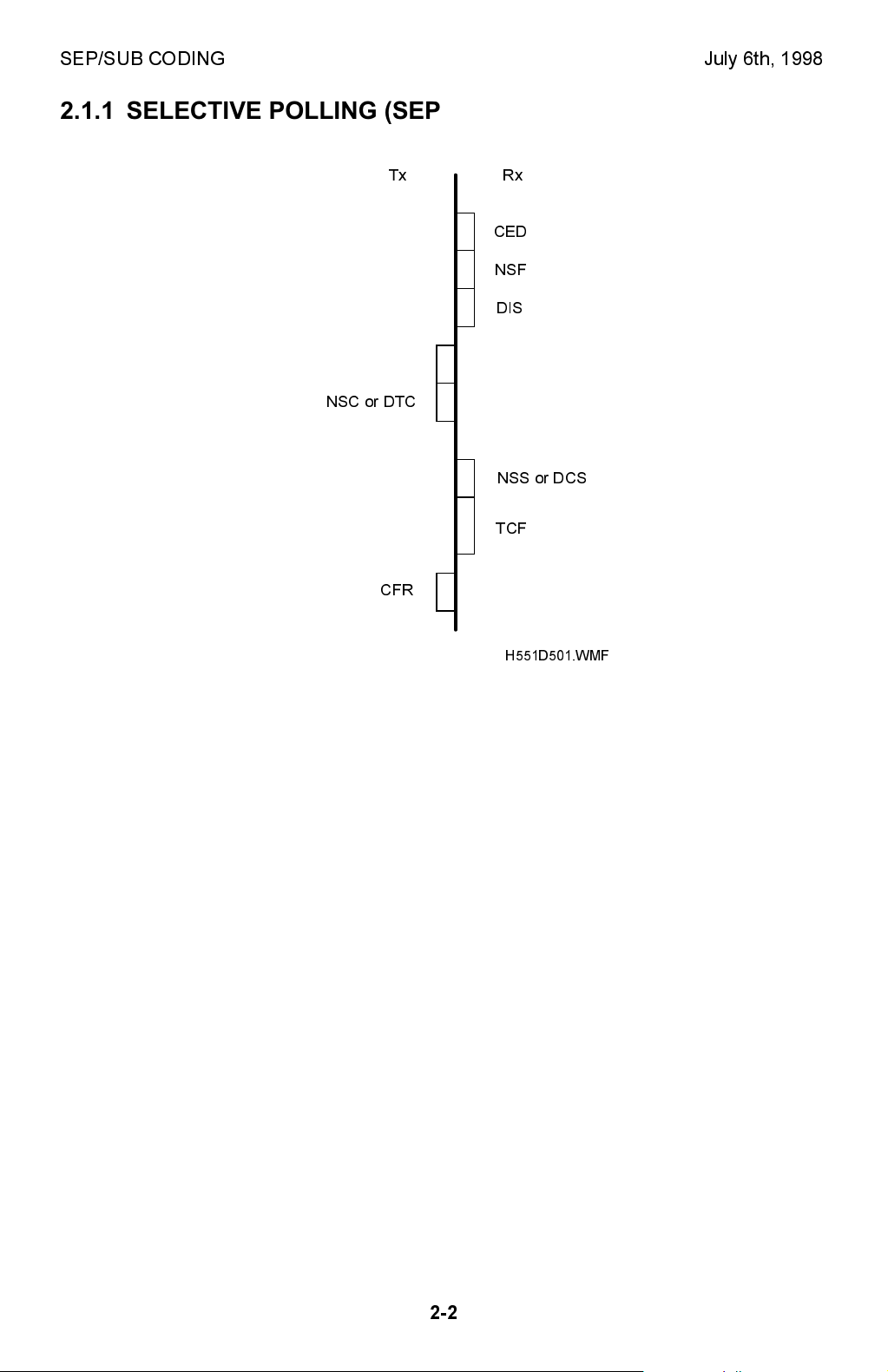
2.1.1 SELECTIVE POLLING (SEP/PWD)
Tx Rx
CED
NSF
DIS
SEP
NSC or DTC
NSS or DCS
TCF
CFR
H551D501.WMF
SEP Signal:
When the Rx terminal receives the SEP signal with the NSC or DTC signal, the Rx
terminal switches over to secured polling transmission using the SEP ID. The SEP
(Selective polling) signal must contain four digits as an ID.
The Rx terminal automatically disconnects the line when any of the following
conditions occurs (error code 0-15).
· When the SEP ID is other than four digits.
· When anything other than numbers is included in the ID.
The communication becomes free polling when the SEP ID programmed is 0000.
PWD Signal:
When the PWD (password) signal is transmitted together with the SEP signal, the
PWD programmed is used as an ID code for stored ID override.
NOTE:
This machine is not capable of receiving PWD signal.
2-2
July 6th, 1998 SEP/SUB CODING
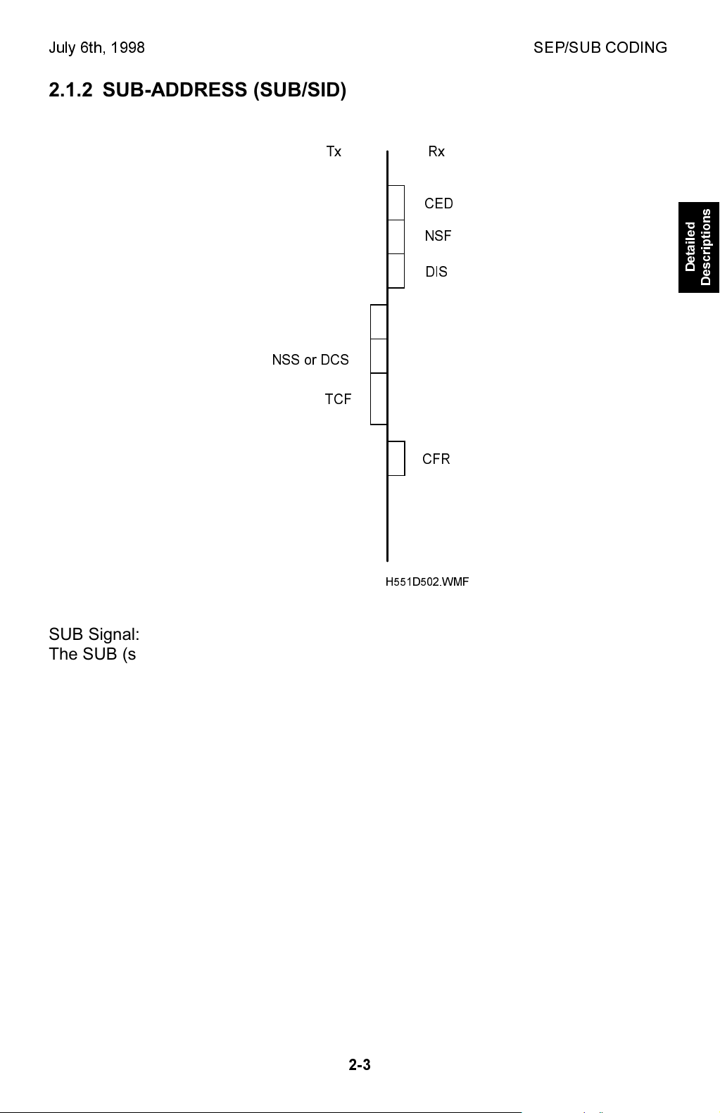
2.1.2 SUB-ADDRESS (SUB/SID)
Tx Rx
CED
NSF
DIS
SUB
NSS or DCS
TCF
CFR
H551D502.WMF
SUB Signal:
The SUB (sub-address) signal transmitted from the Tx terminal contains a
confidential ID. A stored message can be printed using the SUB ID as confidential
ID override.
Detailed
Descriptions
The SUB ID must contain four digits. The receiving terminal automatically
disconnects the line when any of the following conditions occurs (error code 0-15).
· When the SUB ID is other than four digits.
· When anything other than numbers is included in the ID.
· When a confidential ID is not programmed in the Rx terminal and when the
transmitted SUB ID is 0000.
A stored message can be printed using the (normal) confidential ID stored in the
machine when the SUB ID sent from the transmitter is 0000.
NOTE:
This machine is not capable of receiving SID signal.
2-3

JBIG COMPRESSION July 6th, 1998
2.2 JBIG COMPRESSION
JBIG (Joint Bi-Level Image Coding Expert Group) is a working group which
consists of members of ITU-T and ISO. The JBIG compression method allows data
compression of approximately 1.2 to 1.3 times the MMR method in text mode, and
2 to 10 times in halftone mode.
JBIG compression is only available in the optional G3 unit.
JBIG compression is disabled when any of the following conditions occurs.
· When JBIG compression is turned off by communication bit switch 00.
· When ECM is turned off by communication bit switch 01.
· When the receiving terminal does not have the JBIG feature.
· When the receiving terminal does not have the ECM feature.
There are two modes for JBIG compression;
· Standard mode: the transmitted data block consists of 128 lines.
· Optional mode: the transmitted data block consists of one page
(transmission speed with this mode is faster).
This machine supports both modes for transmission and reception. Which mode to
use for communication is determined during handshaking.
Cross reference:
Section 4.2 Bit switches
Communication bit switch 00 bit 5: JBIG reception mode
0: Standard mode only 1: Standard mode and optional mode (default)
Communication bit switch 00 bit 6: Priority of JBIG mode used for transmission
0: Standard mode 1: Optional mode (default)
Please note that transmission speed with the optional mode is faster.
Data Compression
JBIG compressed data is called the Bi-level Image Entity (BIE).
The BIE consists of a header frame (BIH: Bi-level Image Header) and compressed
data frame (BID: Bi-level Image Data).
The BIH frame contains information such as main scan width (pixels), sub scan
length, and compression mode (standard/optional) used.
The BID frame contains the actual data.
BIH
(Bi-Level Image
Header)
BIE: Bi-level Image Entity
BID
(Bi-Level Image Data)
Page Data
Image DataHeader
H551D503.WMF
2-4

July 6th, 1998 MEMORY RECEPTION CONDITIONS
2.3 MEMORY RECEPTION CONDITIONS
User parameter switch 05 bit 1 allows the user to select how to treat an incoming
message that is without RTI or CSI.
User parameter switch 05 bit 1:
Memory reception if no RTI or CSI received 0: Possible, 1: Impossible
If 0 is selected, the machine receives all message regardless of RTI and CSI.
When this is set to 1 (default setting), the following bit switch works in combination
with the user parameter setting.
System bit switch 11 bit 6:
Conditions for memory reception if no RTI or CSI is received.
0: Memory reception is available only when RTI or CSI is received.
1: Memory reception is always available unless there is a mechanical (printer)
error.
The default setting is set to 1.
The default setting means that if the printer is working, all messages will be
received, regardless of the user parameter setting. But the user can decide
whether or not to print messages that have no RTI or CSI. However, when there is
a mechanical error in the printer, the machine rejects such a message because no
trace of the sender will be stored in the machine.
Detailed
Descriptions
This switch has been added from the LFO model.
2-5

LINE TYPE CHANGE July 6th, 1998
2.4 LINE TYPE CHANGE
When the machine is initially used only with the PSTN, the line type programmed
with phone numbers in Quick Dials and the Speed Dials is stored as PSTN G3.
Later, if the line connection is changed so that G3 is to be used only with the ISDN,
the communication port for all stored Quick and Speed Dials must be changed to
ISDN G3.
This feature allows the communication mode and port to be changed for all stored
numbers at once.
Procedure:
1) Change the data in the following RAM addresses.
4B5846(H) - Current line type setting.
4B5847(H) - Line type to be used after this procedure.
NOTE:
2) Turn the main switch off and on.
3) After this procedure, the data programmed automatically returns to FF(H).
The default setting for the above addresses are FF(H).
Then, the machine checks all phone numbers stored in Quick Dials, Speed
Dials, AI Redial, and Forwarding Stations. If the communication mode and
the port setting for a number is the same as specified for the current setting
in the above address, the machine changes these to the new setting.
Setting:
Bit 0 and 1: Communication mode
Bit 2 to 4: Communication port
Bit 5 to 7: Not used
Example:
If you wish to change the port setting from PSTN G3 to ISDN G3,
change the data to 00(H) (0000 0000) in the address 4B5846(H)
change the data to 0C(H) (00001100) in the address 4B5847(H)
Bit 1 0 Setting
0 0 G3
0 1 G4
1 0 Not used
Bit 4 3 2 Setting
0 0 0 PSTN1 (Standard G3)
0 0 1 PSTN2 (Optional G3 unit)
0 1 1 ISDN
1 0 0 Any available port
(This setting can be used only when an optional G3 or G4 unit is
installed in the machine.)
Other settings - Not used
NOTE:
Do not use this procedure if there are any files stored in the memory
awaiting transmission.
2-6
July 6th, 1998 V.8/V.34 PROTOCOL
2.5 V.8/V.34 PROTOCOL
NOTE:
1) Please refer to the V.8/V.34 Training Manual for overall information
about V.8/V.34 protocol.
2) This section explains only functions that are specific to this machine.
3) ANSam length has been changed from 3.2 s to 3.7 s for this model
(from June, 1998).
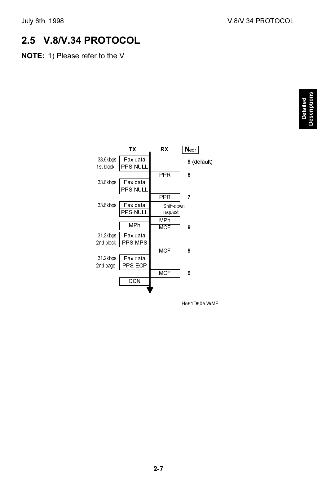
2.5.1 DATA RATE CHANGE PROCEDURE
Shift-down Request from Receiving Terminal
33.6kbps
1st block
33.6kbps
33.6kbps
31.2kbps
2nd block
31.2kbps
2nd page
TX RX
Fax data
PPS-NULL
Fax data
PPS-NULL
Fax data
PPS-NULL
MPh
Fax data
PPS-MPS
Fax data
PPS-EOP
DCN
PPR
PPR
Shift-down
request
MPh
MCF
MCF
MCF
N
9
8
7
9
9
9
Detailed
Descriptions
eor
(default)
H551D505.WMF
· Neor: Number of frame re-transmission until the Tx terminal sends DCN to
terminal the communication. This number is fixed at 9, not adjustable.
If this machine has sent two PPRs for one ECM block, it will request one step shiftdown to the sender terminal in the next control channel.
2-7
V.8/V.34 PROTOCOL July 6th, 1998
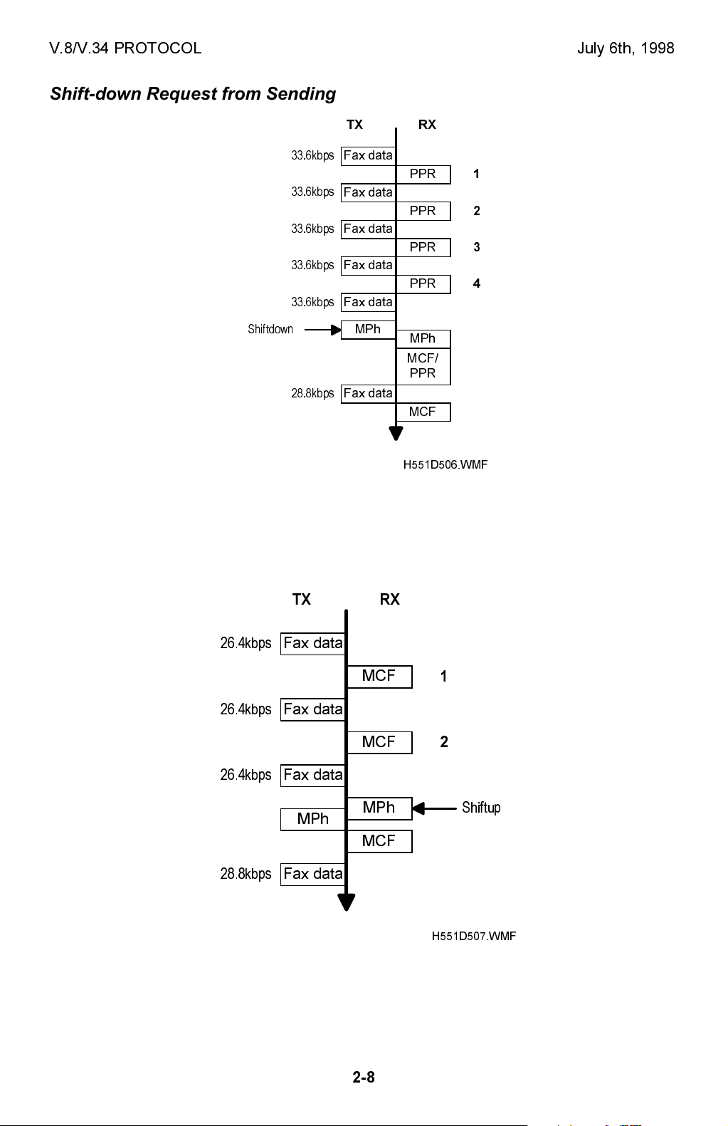
Shift-down Request from Sending Terminal
TX RX
33.6kbps
33.6kbps
33.6kbps
33.6kbps
33.6kbps
Shiftdown
28.8kbps
Fax data
Fax data
Fax data
Fax data
Fax data
MPh
Fax data
PPR
PPR
PPR
PPR
MPh
MCF/
PPR
MCF
H551D506.WMF
1
2
3
4
If this machine has received four PPRs for one ECM block, it will request two step
shift-down to the receiving terminal in the next control channel.
Shift-up Request from Receiving Terminal
TX RX
26.4kbps
26.4kbps
26.4kbps
Fax data
Fax data
Fax data
MPh
MCF
MCF
MPh
1
2
Shiftup
MCF
28.8kbps
Fax data
H551D507.WMF
If this machine has sent two consecutive MCFs and when it detects line condition
to be good, it will request one step shift-up to the sender terminal in the next
control channel.
2-8

July 6th, 1998 SG3-V.34 BOARD
2.6 SG3-V.34 BOARD
Standard
NCU
MFCE
CCP
CPU
(RU8)
DTMF
Receiver
DMAC JBIGIF TONEDPRAM
MN195003MFL
Modem
Hybrid IC
Flash ROM
(4MB)
Modem
DATA/ADDRESS BUS
Flash ROM
(4MB)
Program
DRAM
(4MB)
JBIG
M65761
SG3-V.34
H551D504.WMF
The SG3-V.34 board enables full dual G3 communication with the standard NCU.
The CCP (Communication Control Processor) contains a CPU, and it controls the
entire board.
1. CCP (Communication Control Processor)
· CPU (RU8)
· DPRAM (Dual Port RAM): Handshaking with the MFCE is done through this
block.
· DMA controller
· JBIG interface
2. ROM
· 512kB (4 Mbit) flash ROM for the system program
· 512kB (4 Mbit) flash ROM for the modem program
Both programs can be updated using the Flash/SRAM data copy board.
Detailed
Descriptions
3. DRAM
· 512kB DRAM shared between the line buffer, ECM buffer, and working RAM.
4. Modem
· A Panasonic MN195003MFL modem is used.
5. JBIG LSI
· JBIG compression LSI
6. DTMF Receiver
2-9
July 6th, 1998 INSTALLING THE MACHINE
3. INSTALLATION
3.1 INSTALLING THE MACHINE
Refer to the Operator's Manual for the installation environment and how to install
and set up the machine.
Refer to section 2.4.5. of the FX4 service manual for how to set up the NCU
hardware in each country.
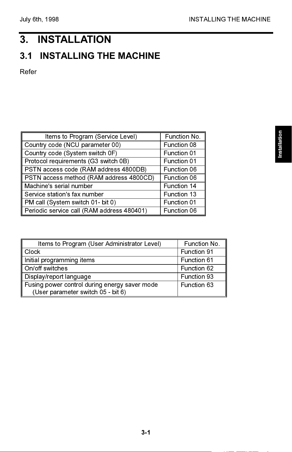
3.2 INITIAL PROGRAMMING
Items to Program (Service Level) Function No.
Country code (NCU parameter 00) Function 08
Country code (System switch 0F) Function 01
Protocol requirements (G3 switch 0B) Function 01
PSTN access code (RAM address 4800DB) Function 06
PSTN access method (RAM address 4800CD) Function 06
Machine's serial number Function 14
Service station's fax number Function 13
PM call (System switch 01- bit 0) Function 01
Periodic service call (RAM address 480401) Function 06
Installation
Items to Program (User Administrator Level) Function No.
Clock Function 91
Initial programming items Function 61
On/off switches Function 62
Display/report language Function 93
Fusing power control during energy saver mode
(User parameter switch 05 - bit 6)
Function 63
3-1
INSTALLING OPTIONAL UNITS July 6th, 1998
3.3 INSTALLING OPTIONAL UNITS
I
CAUTION
Do the following before installing an optional unit:
1. Print out all messages stored in the memory.
2. Print out the lists of user-programmed items and the system parameter list.
3. Turn off the main switch, and disconnect the power plug.
NOTE:
· Refer to the Operators Manual for the user installable options.
· For the Function Upgrade Card and Fax On Demand Card, be sure to read
section 3.3.9. after installation.
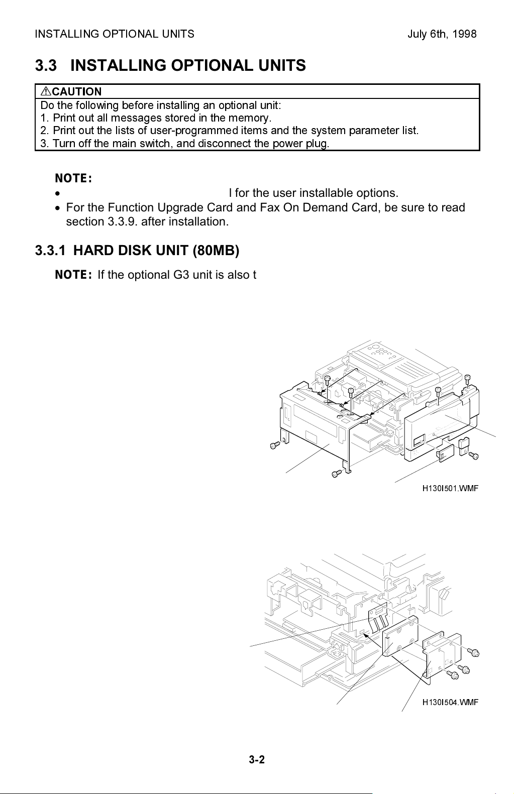
3.3.1 HARD DISK UNIT (80MB)
NOTE:
Installation Procedure
1. Remove the rear cover [A] (4
screws), left cover [B] (3 screws and
the connector cover), and the IC card
slot cover [C].
If the optional G3 unit is also to be installed, install this option before
installing the G3 unit.
[B]
2. Attach the bracket [D] to the hard
disk unit [E] (4 screws). Hook the
grounding plate [F] on the bracket
and secure the hard disk unit to the
machine (2 screws).
[F]
3-2
[A]
[E]
[C]
[D]
H130I501.WMF
H130I504.WMF
July 6th, 1998 INSTALLING OPTIONAL UNITS
[I]
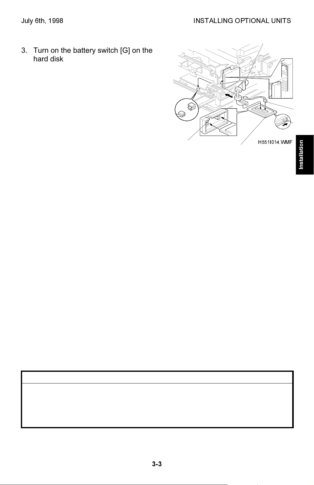
3. Turn on the battery switch [G] on the
hard disk interface card [H].
4. Connect the harness [I] to the hard disk
interface card [H] and to the hard disk
unit.
Then insert the hard disk interface card
into the upper card slot [J].
NOTE:
Do not connect the harness [K]
at this time.
5. Turn on the main switch and enter the
[J]
[H]
H551I014.WMF
service mode. Then do the following:
· Set system bit switch 05 bit 4 to "1",
system bit switch 00 bit 1 to 1, then
exit the service mode. The machine
then does the RAM reset level 3.
· Enter service function 16 and select
0 (INITIALIZE) to initialize the hard
disk.
If OK is displayed, exit the service mode and turn off the main switch.
[K]
[G]
Installation
6. Connect the harness [K] (2 pins) from the hard disk interface card to CN73 on
the FDU.
7. Put back the rear cover and the left cover. Turn on the main switch and enter
the service mode.
Print the memory dump list (service function 06) of the following addresses and
data.
70001E(H) - 50(H) 700022(H) - 00(H)
70001F(H) - 00(H) 700023(H) - 00(H)
700020(H) - FF(H) 700024(H) - 00(H)
700021(H) - FF(H) 700025(H) - 80(H)
If any of these addresses contain a different value, format the hard disk
(service function 16).
End of Procedure
CAUTION
I
The hard disk interface card contains a lithium battery. The danger of explosion
exists if a battery of this type is incorrectly replaced.
Replace only with the same or an equivalent type recommended by the
manufacturer. Discard used batteries in accordance with the manufacturer's
instructions.
3-3
INSTALLING OPTIONAL UNITS July 6th, 1998
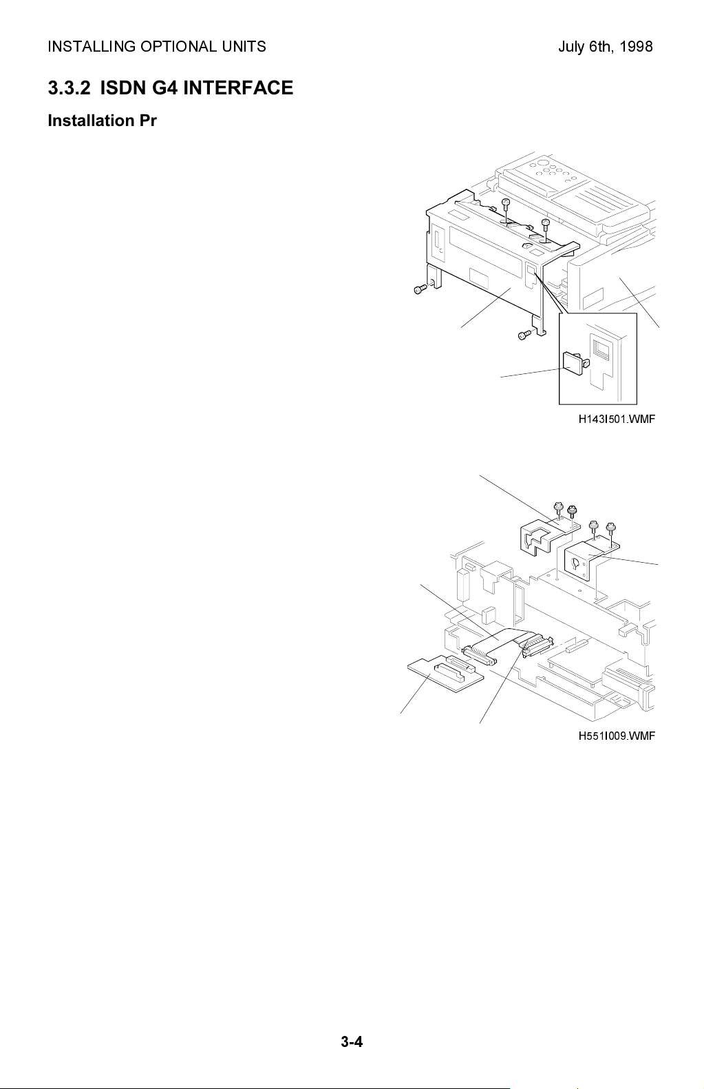
3.3.2 ISDN G4 INTERFACE
Installation Procedure
1. Remove the rear cover [A] (4 screws), and
the left cover [B] (3 screws and the PFU
connector cover. Then remove the small
cover [C] from the rear cover as shown.
[A] [B]
[C]
H143I501.WMF
2. Remove the PIF brackets [D] and [E].
Bend the flat cable [F] as shown and
connect it to the FCE (CN4) and the G4
interface board [G].
NOTE:
Make sure that the core [H] is
placed by the FCE as shown.
Make sure that the ▼ marks face
each other at each end.
[G]
[D]
[E]
[F]
[H]
H551I009.WMF
3-4
July 6th, 1998 INSTALLING OPTIONAL UNITS
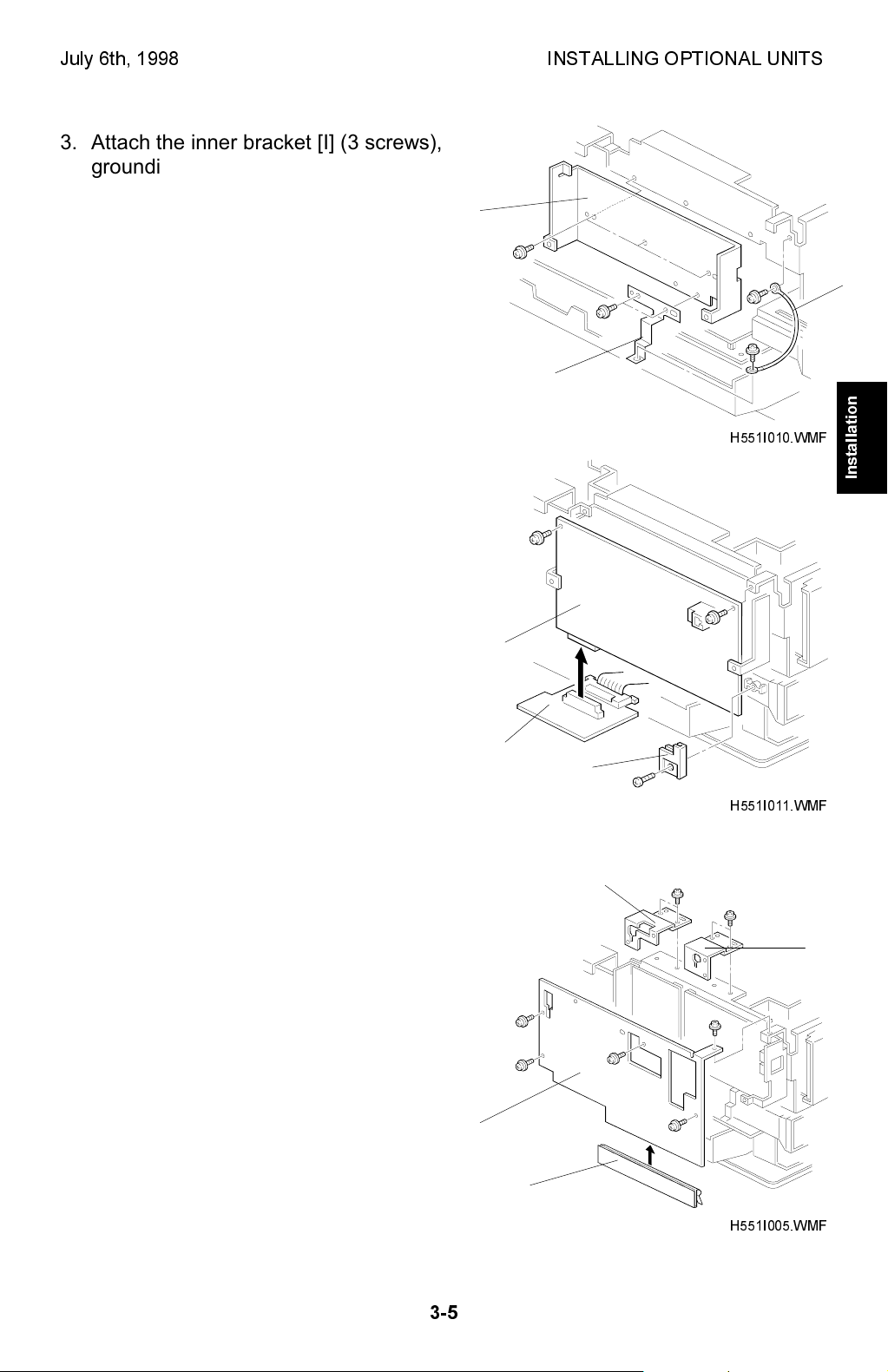
3. Attach the inner bracket [I] (3 screws),
grounding plate [J] (3 screws), and the
ground wire [K] as shown.
[I]
[J]
H551I010.WMF
4. Connect the ISDN board [L] to the G4
interface board [G]. Then, secure the ISDN
board to the machine with 2 screws and
the support holder [M] (1 tapping screw).
[K]
Installation
[G]
5. Replace the PIF brackets [D] and [E] which
were removed in step 2.
Attach the ground plate [N] to the outer
bracket [O]. Then attach the outer bracket
to the machine (5 screws).
NOTE:
Align the ground plate with the left
edge of the outer bracket.
[O]
[L]
[M]
H551I011.WMF
[D]
[E]
3-5
[N]
H551I005.WMF
INSTALLING OPTIONAL UNITS July 6th, 1998
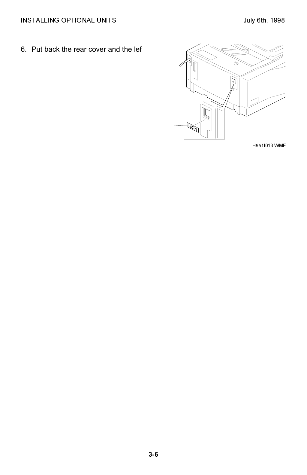
6. Put back the rear cover and the left cover.
Attach the ISDN decal [P] to the small
cover as shown. Connect the ISDN cable
so that the core is closer to the machine.
NOTE:
Make sure that the grounding plate
does not come off when replacing
the rear cover.
[P]
H551I013.WMF
7. Plug in the machine and turn on the main
switch.
Set Communication Bit Switch 16 bit 2 to
1. Then turn the machine off and on to
enable the ISDN unit.
8. Input the initial settings with user function
61 and service function 17.
Please refer to the ISDN option service manual for details.
Make the following settings if necessary.
· System bit switch 0A bit 1: Default communication mode.
Bit 1 0: G3 1: G4
· System bit switch 0A bit 6: Line used for G3 transmission.
Bit 6 0: PSTN 1: ISDN
· System bit switch 0A bit 7: Line used when the machine falls back to G3 from
G4
Bit 7 0: PSTN 1: ISDN
· System bit switch 18 bits 0 and 1: Default communication line for
transmission
Bit 1 Bit 0 Setting
0 0 PSTN 1 or PSTN 2 (Default setting)
0 1 PSTN 1 (Standard G3 Unit)
1 0 PSTN 2 (Optional G3 Unit must be installed)
1 1 ISDN (Optional G4 Unit)
NOTE:
Make sure that you input the following subscriber numbers when you
connect the machine under the US National ISDN network.
· Subscriber number: G4 Subscriber No.1 (Main)/ G3 Subscriber No.1 (Main)
· SPID Number: G4 Subscriber No.2 (Sub)/ G3 Subscriber No.2 (Sub)
End of Procedure
3-6
July 6th, 1998 INSTALLING OPTIONAL UNITS
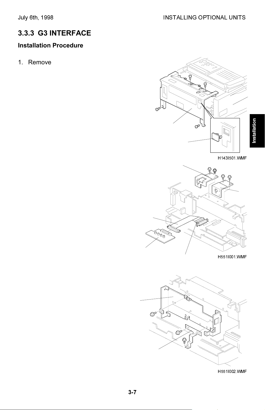
3.3.3 G3 INTERFACE
Installation Procedure
1. Remove the rear cover [A] (4 screws), and
the left cover [B] (3 screws) and the PFU
connector cover. Then, remove the small
cover [C] from the rear cover as shown.
[A]
[B]
2. Remove the PIF brackets [D] and [E].
Bend the flat cable [F] as shown and
connect it to the FCE (CN4) and the G3
interface board [G].
NOTE:
Make sure that the core [H] is
placed by the FCE as shown.
Make sure that the ▼ marks
face each other at each end.
3. Attach the inner bracket [I] (3 screws)
and the grounding plate [J] (3 screws) as
shown.
[I]
[G]
[F]
[D]
[H]
[C]
Installation
H143I501.WMF
[E]
H551I001.WMF
3-7
[J]
H551I002.WMF
INSTALLING OPTIONAL UNITS July 6th, 1998
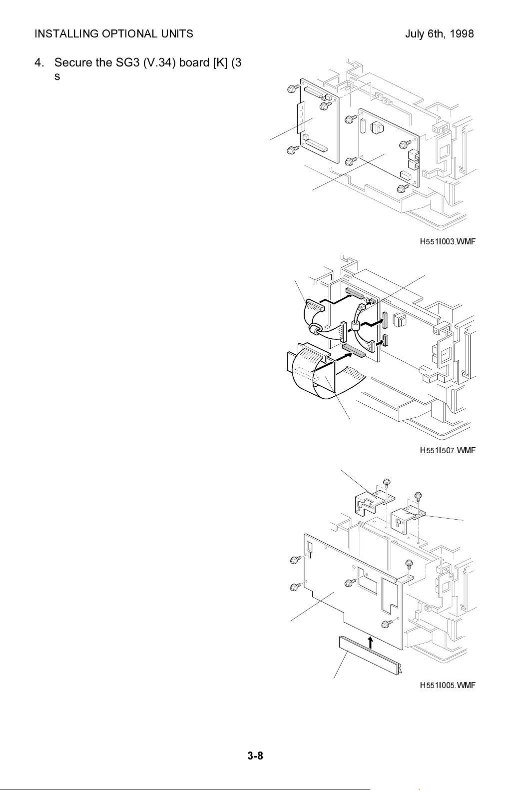
4. Secure the SG3 (V.34) board [K] (3
screws) and the optional NCU board [L]
(4 screws).
[K]
[L]
H551I003.WMF
5. Connect the harness [M] and [N]
between the SG3 (V.34) board and the
[M]
[N]
optional NCU board.
Also connect the G3 interface board [G]
to the SG3 (V.34) board.
NOTE:
The harness [N] is not used in
the USA models.
The core is not installed on the
harness [M] in the USA models.
6. Replace the PIF brackets [D] and [E]
which were removed in step 2.
Attach the grounding plate [O] to the
outer bracket [P]. Then attach the outer
bracket to the machine.
Align the grounding plate with the left
edge of the outer bracket.
[P]
[O]
[G]
H551I507.WMF
[D]
[E]
H551I005.WMF
3-8
July 6th, 1998 INSTALLING OPTIONAL UNITS
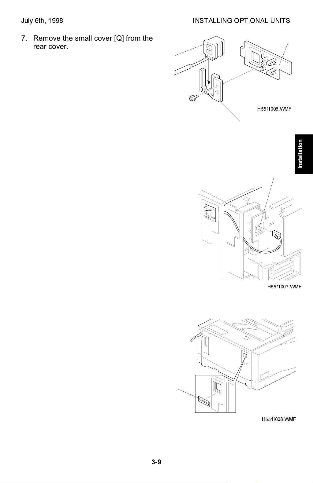
7. Remove the small cover [Q] from the
rear cover. Set the phone line harness
[R] in the bracket [S]. Then attach it to
[R]
the small cover [Q] (1 tapping screw).
8. Put back the small cover and connect the phone
line harness to the connector [T] as shown.
[Q]
H551I006.WMF
[S]
Installation
[T]
9. Put back the rear cover and the left cover.
Attach the Line 2 decal [U] on the small
cover. Make sure that the grounding plate
does not come off when replacing the rear
cover.
3-9
H551I007.WMF
[U]
H551I008.WMF
 Loading...