

Ricoh FAX2700L SPECIFICATIONS fx2700

FX6
RICOH FAX2700L
SERVICE MANUAL
May 29th, 1995
Subject to change
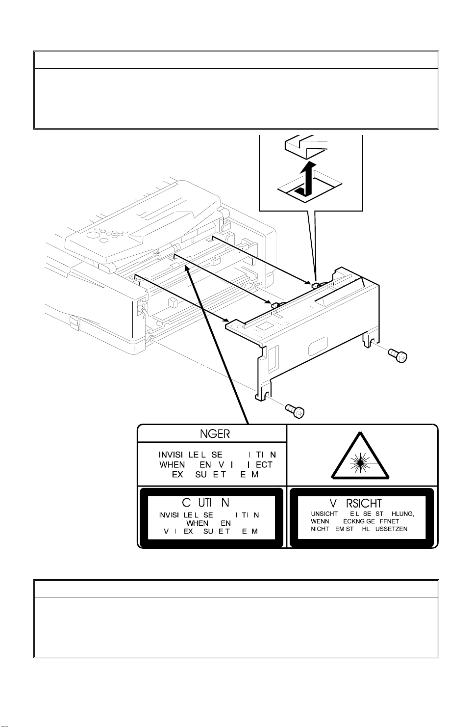
WARNING
I
THIS MACHINE CONTAINS A LASER BEAM GENERATOR. LASER
BEAMS CAN CAUSE PERMANENT EYE DAMAGE. DO NOT OPEN THE
LASERUNIT OR LOOK ALONG THE LASER BEAM PATH WHILE THE
MAIN POWER IS ON.
Lithium Batteries (Memory Back-up)
CAUTION
I
The danger of explosion exists if a battery of this type is incorr ec tly
replaced. Replace only with the same or an equival ent type
recommended by the manufacturer. Discard used batteries in
accordance with the manufactur er’s instructions.

May 29th, 1995 OVERALL MACHINE INFORMATION
SPECIFICATIONS
1. OVERALL MACHINE INFORMATION
1.1. SPECIFICATIONS
Type
Desktop type transceiver
Circuit
PSTN, PABX
Connection
Direct couple
Document Size
Length:
105 - 420 mm [4.1 - 16.5 ins]
Up to 1.2 m [47.2 ins], manually assisted
Up to 14 m [46 ft] after adjustment
Width:
148 - 304 mm [5.8 - 12.0 ins]
Thickness:
0.05 to 0.2 mm [2 to 8 mils]
(equivalent to 50 - 80 g/m
Document Feed
Automatic feed, face down
ADF Capacity
30 sheets (using 20 lb or 80 g/m
Scanning Method
Contact image sensor
Maximum Scan Width
216 mm [8.5 ins] ± 0.25%
Scan Resolutions
Main scan: 8 dots/mm [203 dpi]
Sub scan:
Standard - 3.85 lines/mm [98 lpi]
Detail - 7.7 lines/mm [196 lpi]
Fine - 15.4 lines/mm [392 lpi]
Memory Capacity
ECM: 64 or 128 kbytes
(depends on the amount of image data)
SAF: 244 kbytes (19 pages/Slerexe letter),
extra 2 Mbyte (186 pages) or 4 Mbyte (350
pages) memory card available
Compression
MH, MR, EFC, MMR, SSC (MMR only with
ECM)
SAF storage for memory tx: MMR and raw
data
2
)
2
paper)
Protocol
Group 3 with ECM
Modulation
V.29 (QAM), V.27ter (PHM), V.21 (FM)
Data Rate (bps)
9600/7200/4800/2400, Automatic fallback
I/O Rate
With ECM: 0 ms/line
Without ECM: 2.5, 5, 10, 20, or 40 ms/line
Transmission Time
9 s at 9600 bps; Measured with G3 ECM using memory for a ITU-T #1 test document
(Slerexe letter) at standard resolution
Printing System
Laser printing, plain paper, dry toner
Paper Size and Capacity
Standard Cassette: 250 sheets
USA: Letter
Europe: A4, A5 sideways
Asia: A4, A5 sideways, F, F4
100 Sheet Cassette (Optional): 100 sheets
USA: Letter, Legal
Europe: A4, A5 sideways
Asia: A4, A5 sideways, F, F4
Universal Cassette (Optional): 250 sheets
Letter , Legal, A4, A5 sideways, F, F4
Maximum Printing Width
208 mm [8.1 ins]
Print Resolutions
Fax and Copy Mode:
Main scan: 16 dots per mm [406 dpi]
Sub scan: 15.4 lines/mm [392 lpi]
Printer Mode: 300 x 300 dpi
Power Supply
USA: 115 ± 20 Vac, 60 ± 1 Hz
Europe/Asia: 187 - 276 Vac, 50 ± 3 Hz
Power Consumption (Base Machine Only)
Standby: Minimum 2 W; Normal 20 W
Transmit: 25 W
Receive: 210 W
Copying: 270 W
Operating Environment
Temperature: 17 - 28 °C [63 - 82 °F]
Humidity: 40 - 70 %Rh
1-1

OVERALL MACHINE INFORMATION May 29th, 1995
SPECIFICATIONS
Dimensions (W x D x H)
475 x 459 x 240 mm [18.7 x 18.1 x 9.4 ins]
Excluding handset, trays, and optional units
Weight
Approx. 17 kg [37 lbs]
Excluding CTM, handset, trays, and optional
units
1-2
May 29th, 1995 OVERALL MACHINE INFORMATION
FEATURES
1.2. FEATURES
KEY: O = Used, X = Not Used,
A = With optional memory only,
B = With optional 100 sheet cassette only
C = With optional counter only
D = With optional handset only
E = PIF
Equipment
ADF O
Book scan X
Built-in handset X
Bypass feed: 1 sheet O
Optional cassette: 100 sheets B
Optional cassette: Universal O
Cabinet X
Counter C
Cutter X
Handset D
Hard disk X
Manual feed mechanism X
Marker (Stamp) O
Monitor speaker O
Optional printer interface E
Video Processing Features
Contrast O
Halftone (Basic & Error Diffusion) O
MTF O
Reduction X
Resolution O
Smoothing to 16 x 15.4 l/mm O
Communication Features - Auto
Automatic fallback O
Automatic redialing O
Confidential reception A
Dual Access O
Substitute reception O
Communication Features -
User Selectable
Action as a transfer broadcaster X
AI Redial (last ten numbers) X
Answering machine interface X
Authorized Reception O
Auto-answer delay time X
Communication Features -
User Selectable
Auto dialing (pulse or DTMF) O
Auto Document O
Auto image density selection X
Auto paper size selection X
Automatic Voice Message X
Batch Transmission (max 6 files) A
Broadcasting O
Chain Dialing O
Communication Result Display X
Confidential ID Override O
Confidential Transmission O
Direct Fax Number Entry O
Economy Transmission X
Fax on demand X
Forwarding A
Free Polling O
Groups (7 groups) O
Group Transfer Station X
Hold X
ID Transmission O
Immediate Redialing O
Immediate transmission O
Keystroke Programs O
Memory transmission O
Multi-step Transfer X
Next Transfer Station X
OMR X
On Hook Dial O
Ordering Toner X
Page Count O
Personal Codes O
Personal Codes with Conf. ID A
Polling Reception O
Polling Transmission O
Polling tx file lifetime in the SAF O
Quick Dial (32 stations) O
Reception modes (Fax, Tel,
Length Reduction X
Remote control features X
Remote Transfer X
Restricted Access O
Secured Polling O
Secured Polling with Stored ID
Override
Secure Transmission X
Auto) O
O
1-3

OVERALL MACHINE INFORMATION May 29th, 1995
FEATURES
Communication Features -
User Selectable
Send Later O
Silent ringing detection X
Specified Image Area X
Speed Dial (90 stations) O
Super Fine Resolution
(16 x15.4 l/mm : 400 x 400 dpi)
Telephone Directory X
Tonal Signal Transmission O
Transfer Request O
Transmission Deadline (TRD) A
Turnaround Polling X
Two- step Transfer X
Two in one X
Voice Request (immed. tx only) X
Communication Features -
Service Selectable
AI Short Protocol O
Auto-reduction override option O
Busy tone detection O
Closed Network (tx and rx) O
Continuous Polling Reception X
Dedicated tx parameters O
ECM O
EFC O
Inch-mm conversion X
Page retransmission times O
Page separation mark O
Protection against wrong conn. O
Resol’n stepdown override option X
Short Preamble X
Well log O
Other User Features
Area code prefix X
Automatic service call Service
Center mark O
Checkered mark X
Clearing a memory file O
Clearing a polling file O
Clock O
Confidential ID A
Copy editing (Erase
Center/Margin)
Copy mode O
X
X
Other User Features
Copy Mode Restriction X
Counters O
Daylight Saving Time O
Destination Check X
Direct entry of names O
File Retention Time X
File Retransmission X
Function Programs O
ID Code O
Label Insertion ("From xxx") O
Language Selection O
LCD contrast control Service
Memory Lock A
Memory Lock ID A
Modifying a memory file X
Multi Sort Document Reception A
Multicopy mode O
Own telephone number O
Power Saver (Night Timer and
standby mode)
Print density control O
Printing a memory file O
RDS on/off O
Reception Mode Switching Timer X
Reception time printing X
Reduction/Enlargement X
Remaining memory indicator O
Remote ID X
Reverse Order Printing A
RTI, TTI, CSI O
Secure ID X
Service Report Transmission O
Speaker volume control O
Specified Cassette Selection B
Substitute reception on/off O
Telephone line type O
Toner Saving Mode O
TTI on/off O
User Function Keys X
User Parameters O
Wild Cards O
O
1-4
May 29th, 1995 OVERALL MACHINE INFORMATION
FEATURES
Reports - Automat ic
Charge Control Report X
Communication Failure Report O
Confidential File Report A
Error Report O
Memory Storage Report O
Mode Change Report X
Polling Clear Report O
Polling Reserve Report O
Polling Result Report O
Power Failure Report O
TCR (Journal) O
Toner Cassette Order Form X
Transfer Result Report X
Transmission Result Report O
Reports - User-initiated
Authorized Reception List O
Charge Control Report X
File List O
Forwarding List A
Group List O
Personal Code List O
Program List O
Quick Dial List O
Specified Cassette Selection List B
Speed Dial List O
TCR O
Transmission Status Report X
User Function List X
User Parameter List O
Service Mode Features
File Transfer O
LCD contrast adjustment O
Line error mark O
Memory file printout (all files) O
Modem test O
NCU parameters O
Operation panel test O
Periodic service call O
PM Call O
Printer mechanism test O
Printer test patterns O
Programmable attenuation X
Protocol dump list O
RAM display/rewrite O
RAM dump O
RAM test O
Ringer test X
Scanner lamp test O
Scanner mechanism test O
Sensor initialization X
Serial number O
Service monitor report O
Service station number O
Software upload/download O
SRAM data download O
System parameter list O
Technical data on the TCR O
Thermal head parameters X
Transmission Status Report X
User data transfer O
Service Mode Features
Auto Paper Select test X
Back-to-back test O
Bit switch programming O
Book mode test X
Buzzer test O
Cable equalizer O
Comm. parameter display O
Counter check O
Country code O
DTMF tone test O
Echo countermeasure O
Effective term of service calls O
Error code display O
Excessive jam alarm O
Memory Files
Max. number of files: 100
Max. number of stations/ file : 13 2
Max. number of stations ove rall: 300
1-5
21
2
3
31
OVERALL MACHINE INFORMATION May 29th, 1995
COMPONENT LAYOUT
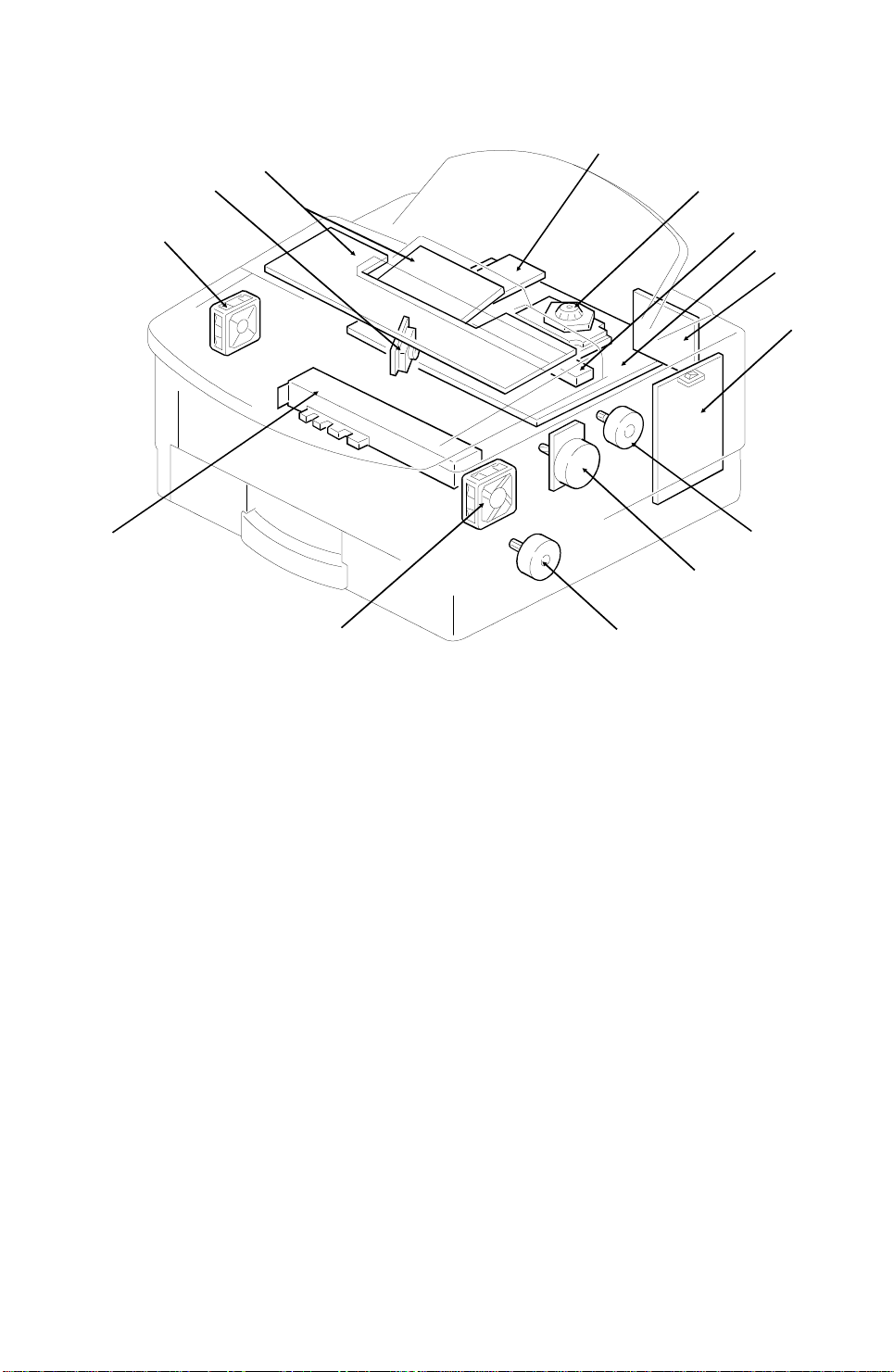
1.3. COMPONENT LAYOUT
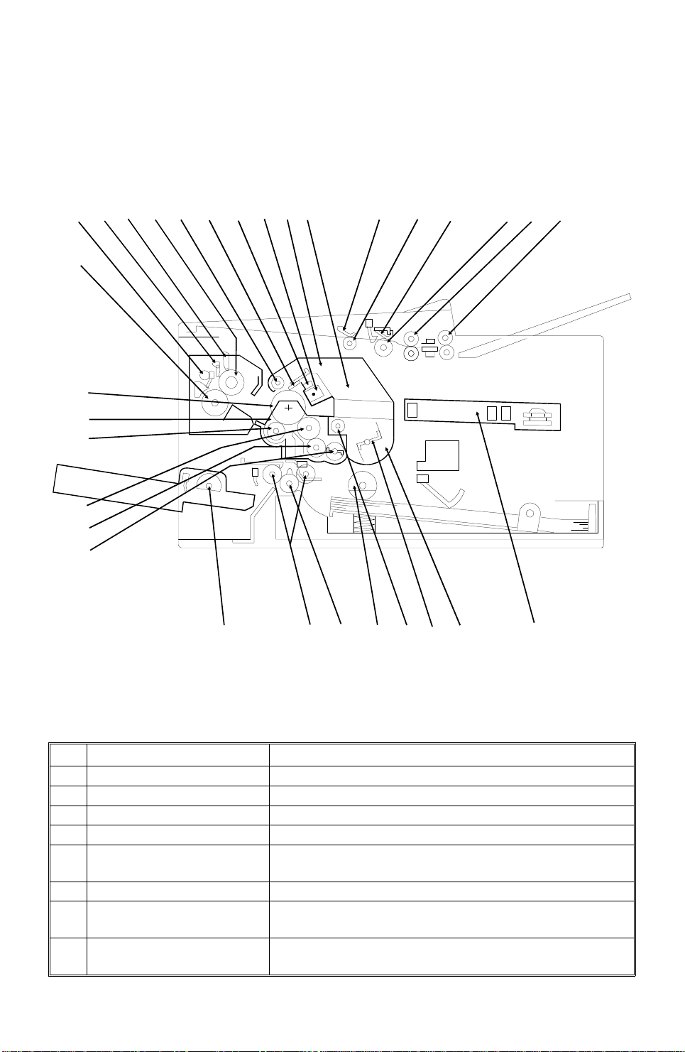
1.3.1. Mechanical Components
9
16
17
18
19
20
15
13
12
11
1014
87
5
6
4
1
22
23
24
25
26
27
28
29
30
No. Name Description
R2 Roller Feeds the document through the scanner.
1
R1 Roller Feeds the document through the scanner.
2
Document Feed Roller Feeds the document into the scanner.
3
Separation Pad Allows one page into the scanner.
4
Pick-up Roller Picks up pages of the document from the document
5
Pressure Plate This applies pressure against the pick-up roller.
6
CTM (Cleaning Toner
7
Magazine)
Used Toner Tank This removes and stores excess toner from the master
8
table one at a time.
This consists of the toner cartridge, cleaning unit, used
toner tank, charge corona unit, and quenching lamp.
after image transfer. It is part of the CTM.
H516V501.wmf
1-6

May 29th, 1995 OVERALL MACHINE INFORMATION
COMPONENT LAYOUT
No. Name Description
Charge Corona Unit This applies a charge to the drum at the start of the
9
Quenching Lamp This removes excess charge from the master at the
10
Cleaning Blade This wipes toner off the OPC drum.
11
Used Toner Collection
12
Roller
Hot Roller Heat from this roller fuses the toner to the copy paper.
13
Cleaning Pad This cleans up and spreads silicone oil on the surface
14
Hot Roller Strippers These take the paper off the hot roller after fusing.
15
Paper Feed-out Rollers These feed the paper out of the printer.
16
Fusing Pressure Roller This applies pressure to the paper during the fusing
17
OPC Drum The latent image is written to this Organic
18
Development Unit This consists of the development roller, toner
19
Transfer Roller This applies a charge to the paper to pull the toner off
20
Development Roller This roller applies toner to the latent image on the drum.
21
Toner Application Roller This roller transfers toner to the development roller.
22
Toner Supply Bar This stirs up and transfers toner to the toner application
23
Paper Feed Rollers (100
Sheet Cassette)
24
Paper Feed Pressure
25
Rollers
Registration Roller This carries out the registration process.
26
Paper Feed Rollers These pick up the top sheet of paper from the stack in
27
Toner Supply Roller This supplies toner to the development unit. It is part of
28
Toner Agitator This stirs up toner in the toner tank, so that it does not
29
Toner Tank This supplies toner to the development unit. It is part of
30
Laser Unit This consists of the LDDR (Laser Diode Driver),
31
print cycle. It is part of the CTM.
end of the print cycle. It is part of the CTM.
This catches the used toner and the transfers the toner
to the used toner tank. It is part of the CTM.
of the hot roller.
process.
Photoconductor Drum.
application roller, toner supply bar, and transfer roller.
the drum and onto the copy paper.
roller.
These pick up the top sheet of paper from the stack in
the optional 100 sheet cassette and feed it into the
printer.
These feed paper from the cassette or bypass feed slot
into the printer.
the cassette and feed it into the printer.
the toner tank.
collect into lumps.
the CTM.
Focusing lens, Fθ Lenses, Hexagonal mirror motor, and
other laser optic components.
1-7

2
3
22
OVERALL MACHINE INFORMATION May 29th, 1995
COMPONENT LAYOUT
1.3.2. Drive Components
12
13
14
15
11
10
9
8
7
56
4
1
21
16
17
18
19
20
No. Name Description
Tx Motor This stepper motor drives the scanner.
1
R1/R2 Rollers These feed the document through the scanner.
2
Document Feed Drive
3
Gear
Document Feed Roller
4
Drive Gear
Pick-up Roller Drive Gear This drives the pick-up roller.
5
Drum Drive Gear This drives the drum.
6
Used Toner Collection
7
Roller Drive Gear
Transfer Roller Drive Gear This drives the transfer roller.
8
Hot Roller Drive Gear This drives the hot roller.
9
Fusing Pressure Roller
10
Drive Gear
This drives the document feed and pick-up rollers.
This drives the document feed roller.
This drives the used toner collection roller (magnetic) in
the used toner tank.
This drives the pressure roller in the fusing unit.
1-8
H516V502.wmf

May 29th, 1995 OVERALL MACHINE INFORMATION
COMPONENT LAYOUT
No. Name Description
Paper Feed-out Roller This feeds printouts out of the machine.
11
Development Roller Drive
12
Gear
Toner Application Roller
13
Drive Gear
Paper Feed Roller Drive
14
Gear (100 Sheet Cassette)
Registration Roller Drive
15
Gear
Paper Feed Motor This stepper motor drives the paper feed mechanisms
16
Paper Feed Roller Drive
17
Gear Box
Paper Feed Roller Drive
18
Gear
Main Motor This brushless dc motor drives the drum, fusing unit,
19
Toner Supply Gear This ensures the supply of toner from the toner tank in
20
Toner Agitator Drive Gear This drives the toner agitator.
21
CTM Drive Gear This drives the CTM.
22
This drives the development roller.
This drives the toner application roller.
This drives the paper feed roller in the optional 100
sheet cassette.
This drives the registration roller.
and the registration roller.
The gears in this box drive the paper feed roller in the
main cassette.
This drives the paper feed roller.
development unit, and CTM.
the CTM, and its distribution across the full length of
the development unit.
1-9
5
6
OVERALL MACHINE INFORMATION May 29th, 1995
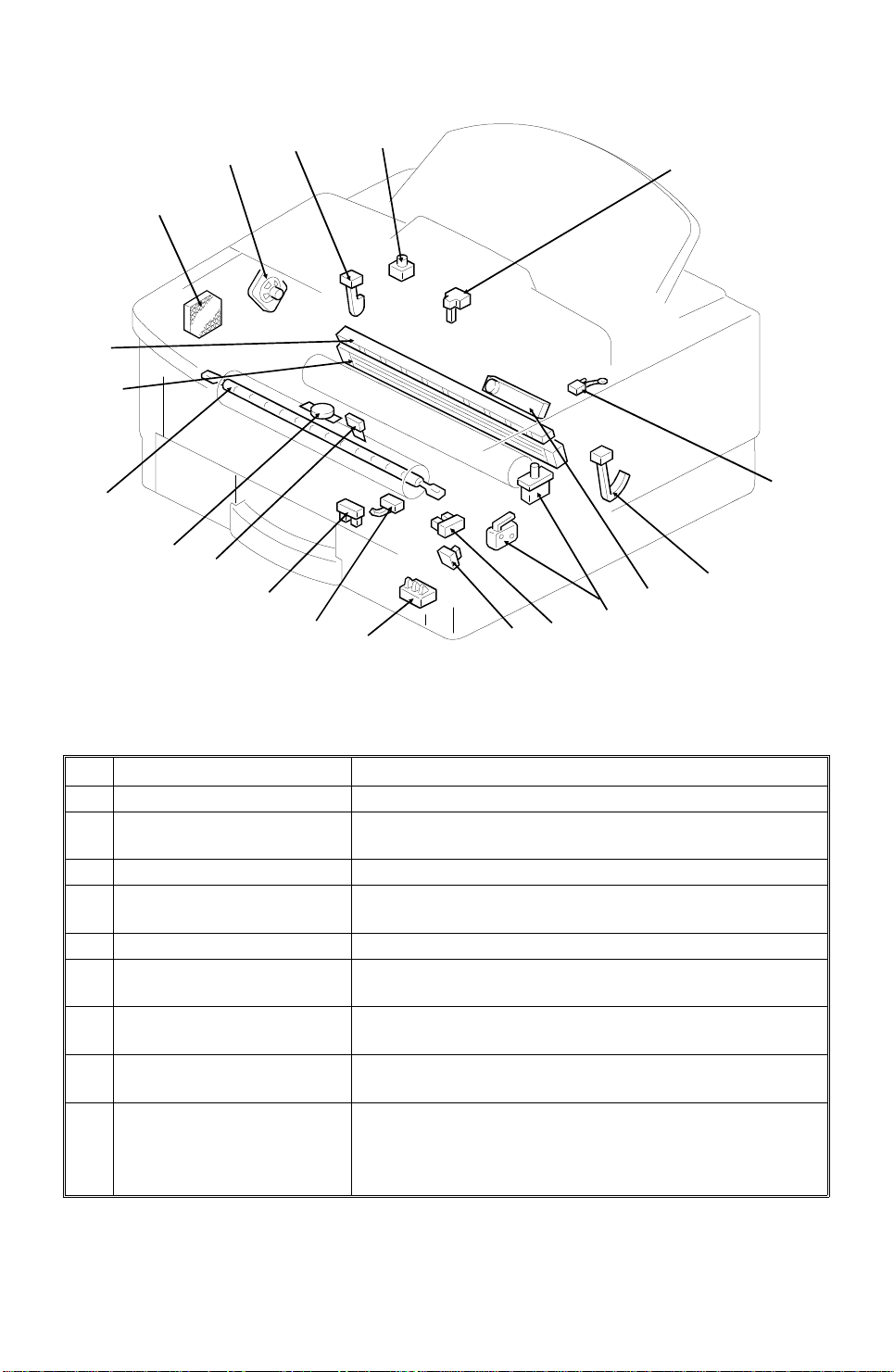
COMPONENT LAYOUT
1.3.3. Electrical Components
7
8
10
9
4
3
2
1
14
13
11
12
H516V503.wmf
1-10

May 29th, 1995 OVERALL MACHINE INFORMATION
COMPONENT LAYOUT
1. PCBs
No. Name Description
FDU (Facsimile Driver
Unit)
3
FCE (Facsimile Control
6
Engine)
NCU (Network Control
2
Unit)
OPU (Operation Panel
7
Unit)
PSU (Power Supply Unit) This board supplies power to the machine, and
1
LDDR (Laser Diode
8
Driver)
Power Pack This supplies high voltages to the corona wire, transfer
10
Contact Image Sensor
Assembly
4
This board contains drivers for the motors, a dc-dc
converter, the energy saving mode cpu, and other drive
electronics.
This board controls the machine. It contains the main
cpu, flash ROM, system RAM, and so on.
This board contains a relay and switches for interfacing
the machine to the network and the handset.
This board controls the operation panel.
switches the fusing lamp on/off.
This board drives the laser diode.
roller, and development rollers.
This sensor reads and converts the light reflected from
the document into an analog video signal. It uses an
RLA (Rod Lens Arr ay) sens or unit.
An LED array which illuminates the document is
contained in this unit.
2. Motors
No. Name Description
Tx Motor This stepper motor drives the scanner.
14
Main Motor This brushless dc motor drives the drum, fusing unit,
13
Paper Feed Motor This stepper motor drives the registration roller and the
12
Hexagonal Mirror Motor This high-speed dc motor drives the hexagonal mirror
5
Ozone Fan Motor This removes ozone-laden air from the vicinity of the
9
Cooling Fan Motor This cools the interior of the machine.
11
development unit, and CTM.
paper feed mechanisms in the cassettes.
in the laser printer optics.
drum, and filters out the ozone.
1-11
15
28
OVERALL MACHINE INFORMATION May 29th, 1995
COMPONENT LAYOUT
20
22
21
19
23
24
18
25
17
26
27
16
29
33
32
31
30
H516V504.wmf
3. Sensors
No. Name Description
Document Sensor This detects the presence of a document in the feeder.
17
Scan Line Sensor This detects when a page is approaching the auto
15
Toner End Sensor This detects when the toner has run out.
31
Paper Size Detector This detects the paper size installed in the cassette.
27
Paper End Sensor This detects when the paper in the cassette has run out.
32
Registration Sensor This detects when paper has reached the registration
26
Fusing Exit Sensor This detects when the paper has been fed out of the
29
Fusing Exit Cover Switch This detects whether the fusing exit cover is open or
28
Bypass Feed Sensor This detects when a sheet of paper has been inserted
25
shading position.
The user must install the correct size indicator.
roller.
printer.
closed.
into the bypass feed slot. Then the registration roller
feeds the paper a short distance into the machine to
prepare for printing, and stops.
1-12

May 29th, 1995 OVERALL MACHINE INFORMATION
COMPONENT LAYOUT
4. Interlock Switches
No. Name Description
Interlock Switches If the fusing unit cover and/or top cover are open, these
30
interlock switches interrupt the +5VLD power supply for
the laser diode and the +24VD power supply for the
power pack, motors, and other components.
5. Others
No. Name Description
Stamper Ass’y This stamps a red circle on each page that is
16
Quenching Lamp This removes excess charge from the drum at the end
20
Charge Corona Unit This applies a charge to the drum at the start of the
21
Thermostat This interrupts the ac power supply to the fusing lamp if
23
Thermistor This monitors the temperature at the hot roller surface.
24
Fusing Lamp The heat from this lamp fuses the toner to the paper.
22
Monitor Speaker This allows the user to listen to the condition of the
18
Zener Diode This ensures that the charge given to the drum by the
33
Ozone Filter This removes ozone-laden air from the vicinity of the
19
successfully fed through the scanner.
of the print cycle. This is a part of CTM.
print cycle. This is a part of CTM.
the temperature of the thermostat surface exceeds
400°C.
telephone line.
charge corona wire does not exceed -750 volts.
drum.
1-13

OVERALL MACHINE INFORMATION May 29th, 1995
COMPONENT LAYOUT
6. Optional Equipment
35
36
37
38
39
40
41
No. Name Description
Counter This counts the number of prints.
34
Printer Interface This allows the machine to be connected to a computer
35
RS232C Interface Board* This allows the machine to be connected to a computer
36
IC Card This increases the SAF memory capacity. Either a 2
37
100 Sheet Cassette This increases the paper capacity of the machine, and
38
Paper Size Detector (100
39
Sheet Cassette)
Paper End Sensor (100
40
Sheet Cassette)
Paper Feed Clutch (100
41
Sheet Cassette)
as a laser printer.
as an external fax device, for example.
MB or 4 MB card can be used.
allows the machine to have more than one paper size
available at the same time.
This detects the paper size installed in the cassette.
This detects when the paper in the cassette has run out.
This transfers drive from the paper feed motor to the
paper feed roller in the cassette.
34
H516V505.wmf
* This option may not be available in some countries.
1-14
May 29th, 1995 OVERALL MACHINE INFORMATION
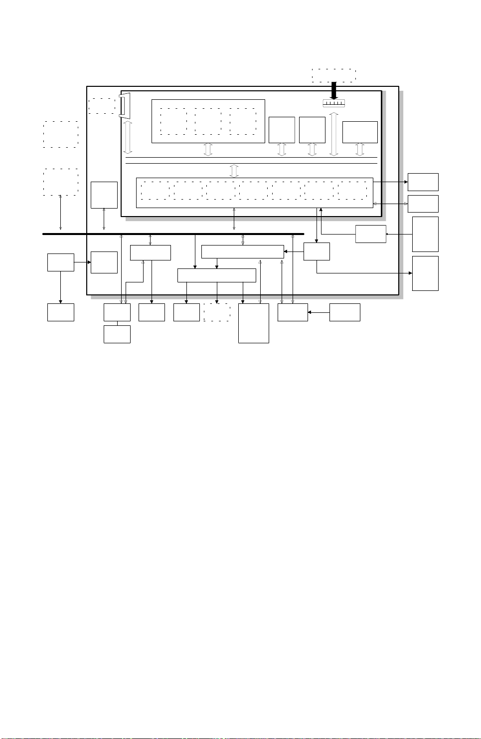
OVERALL MACHINE CONTROL
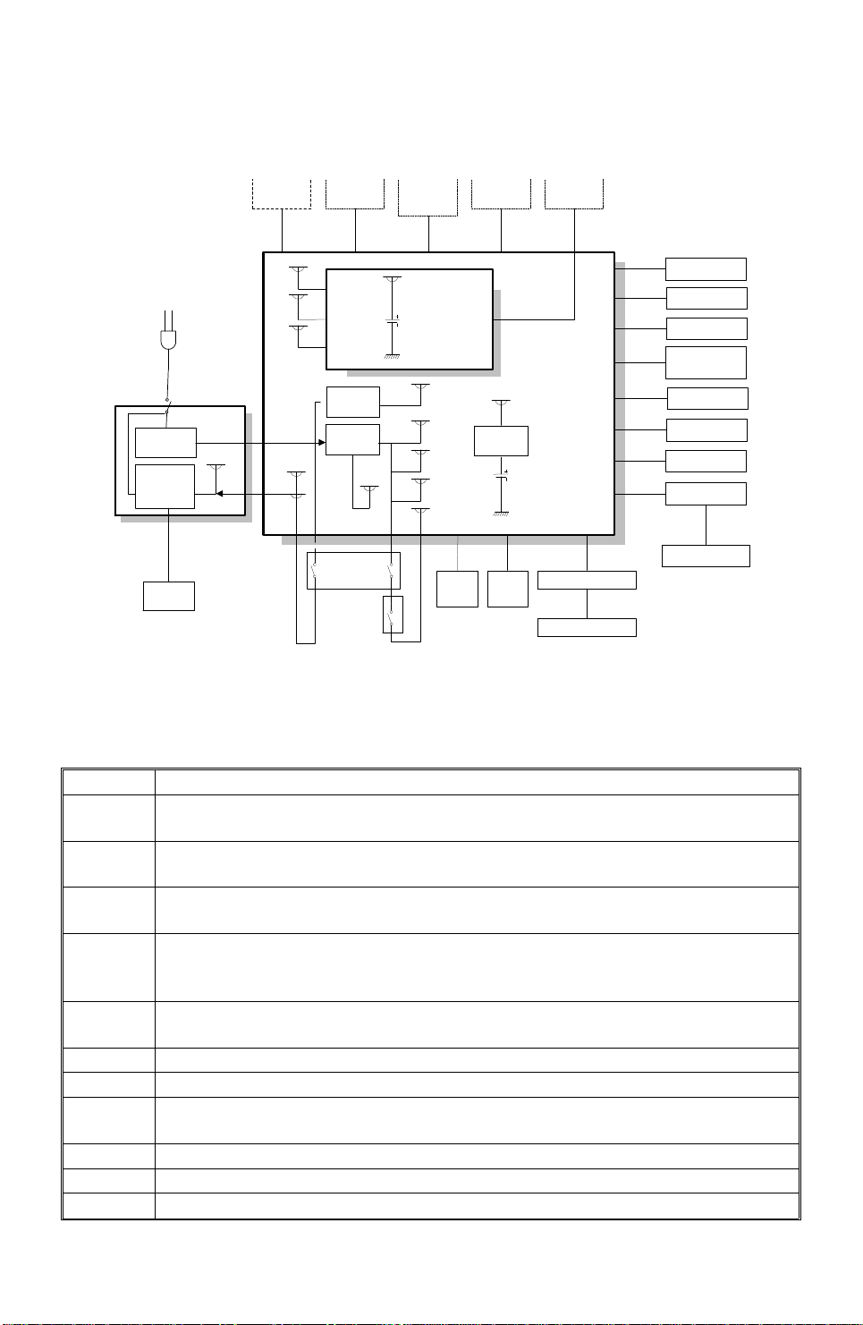
1.4. OVERALL MACHINE CONTROL
Optional
100 Sheet
Cassette
Optional
Printer I/F
PSU
Fusing
Lamp
Optional
IC Card
FDU
Energy
Saver
CPU
DC-DC
Converter
Handset
FCE
MDM
FCIP
Hybrid IC
(HIC)
SpeakerNCU
Working
RAM
Control
Signals
CPU
RU8
Power
Pack
DRAM
ECM/SAF
Memory
Page
Memory
DATA/ADDRESS BUS
DMAC DCR DIP LIF
External I/O (EXIO)
Driver
Optional
Counter
Scanner
and
printer
components
and
sensors
System
ROM
(Flash)
Operation
Panel
System
RAM
(SRAM)
Drivers
(FPD)
Optional
RS232C I/F
Sensors
PRIF
Video
SRAM
Amplifier
LDDR
Thermistor
Contact
Image
Sensor
Tx
and
paper
feed
motors
H516V506.wmf
The FCE (Facsimile Control Engine) contains the FCIP (Facsimile Control
and Image Processor), DRAM, SRAM, System ROM, and video processing
memory, and controls the entire system through the FDU (Facsimile Driver
Unit).
There are two cpus in the mach ine : the main cpu (FCIP) on the FCE and th e
energy saver cpu on the FDU. In energy saver mod e, the main CPU switches
off and the energy saver CPU takes over.
The FCIP consist s of th e following component blocks:
• MDM - Modem• RU8 CPU - Main CPU
• DMAC - DMA Controlle r• LIF- Laser Interface
• DIP - Digital Image Processor• PRIF - Printer Interface
• DCR - Data Compression and Reconstruction
The 1 MB DRAM contains the SAF memory, ECM buffer memory, work area,
and page memory. The SAF memory can be extended by 2 or 4 Mbytes with
an IC card.
A 512 KB (4 Mbit) flash ROM is used for the system ROM. Software in this
ROM can be rewritten from the IC card slot or by RDS.
1-15

OVERALL MACHINE INFORMATION May 29th, 1995
VIDEO DATA PATH
1.5. VIDEO DATA PATH
1.5.1. Transmission
Original
Contact Image Sensor
Assembly
LED Array
Image Sensor
FDU
Amplifier
FCE
DCR
ECM/
SAF
Memory
DIP
FCIP
MDM
Amplifier
Attenuator
HIC
NCU
Video
Processing
Memory
DRAM
SAF IC
Card
DIP: Digital Image Processor
Line
Buffer
/FIFO
Memory
DATA/ADDRESS BUS
DCR: Data Compression & Reconstruction
MDM: Modem
To the network
H516V507.wmf
Immediate Transmission:
Scanned data form the contact imag e sen sor pa sses to the DI P block in the
FCIP. Afte r an alo g/digital video processing, the DCR block compresse s t he
data for transmission. The compressed data then passe s either to the FIFO
memory or to the ECM memory, before it is sent to the telephone line through
the modem.
Memory Transmission:
First, the scanned data is sto red in the SAF memory after compression in the
DCR block.
At the time for transmission, the DCR block decompre sses th e data from the
SAF memory, then compresses it again after handshakin g with the other te rminal is done. The compressed data the n passes eit he r to the FIFO memory
or to the ECM memory, before it is sent to the telephone line through th e
modem.
1-16
May 29th, 1995 OVERALL MACHINE INFORMATION
VIDEO DATA PATH
1.5.2. Reception
From the Network
LIF: Laser Interface
DCR: Data Compression & Reconstruction
NCU
MDM: Modem
FDU
HIC
FCE
Amplifier
MDM
FCIP
LIF
DATA/ADDRESS BUS
ECM/SAF
Memory
Page
Memory
LDDR
Copy Paper
H516V508.wmf
DRAM
DCR
Line Buffer
/FIFO
Memory
Data from the line p asse s to the modem throu gh th e NCU a nd hyb rid IC. After the modem demod ula tes the data, the decompre ssed dat a pa sses to the
DCR block, through either the FIFO or the ECM memory, where the data is
decompressed to rast er image data. At the same time , t he compressed data
passes to the SAF memory as a backup in case of mechanical problems during printing (substit ute reception).
The raster image data is the n passe d to the page memory for printing. After a
page of data has been stored in the page memory, the data is sent to the
LDDR through the LIF block.
1-17
OVERALL MACHINE INFORMATION May 29th, 1995
VIDEO DATA PATH
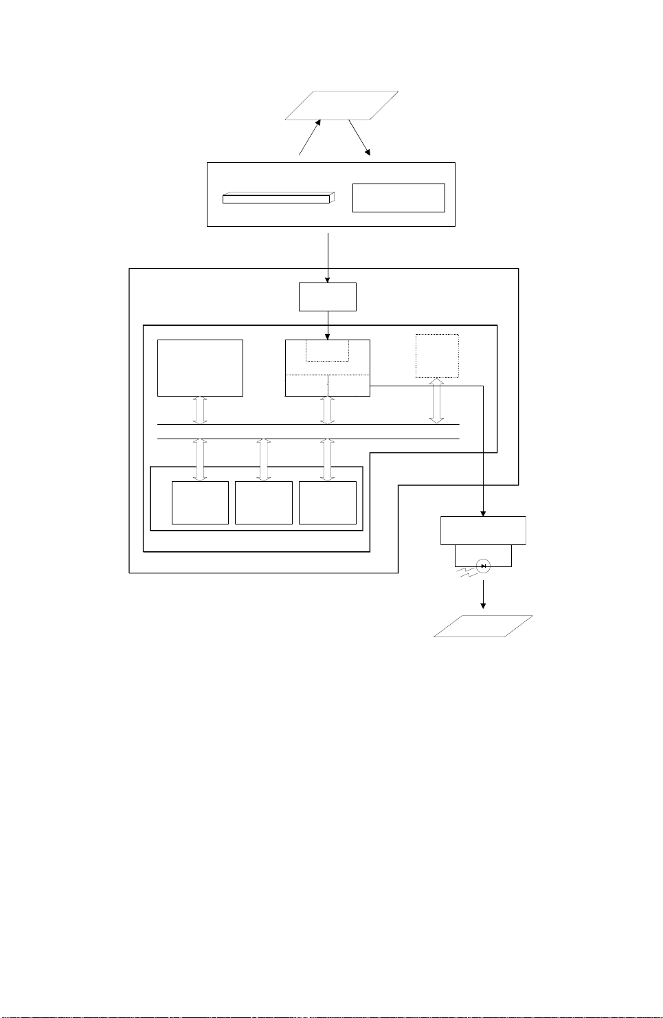
1.5.3. Copying
Original
Contact Image Sensor Assembly
Image Sensor
LED Array
FDU
Amplifier
FCE
LDDR
DRAM
Video
Processing
Memory
Line Buffer
/FIFO
Memory
DCR
DATA/ADDRESS BUS
ECM/SAF
Memory
DIP
FCIP
Page
Memory
LIF
SAF
Memory
IC Card
LIF: Laser Interface
DCR: Data Compression & Reconstruction
DIP: Digital Image Processor
Copy Paper
H516V509.wmf
Single copy
The scanned data passe s to th e pa ge me mory af ter video processing in the
DIP block. After a page of data ha s be en stored in the page memo ry, the data
is sent to the LDDR through the LIF block.
Multi-page copy
The scanned data passe s to th e SAF memory after video processing (DIP)
and compression (DCR). After a pa ge of data has been stored in t he SA F
memory, the data passes to the DCR block again for de comp ression, then it
passes to the page memory for print ing .
1-18

May 29th, 1995 OVERALL MACHINE INFORMATION
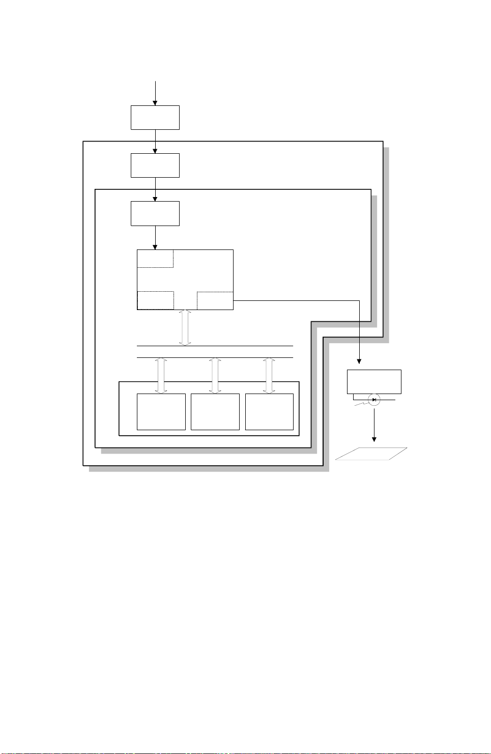
VIDEO DATA PATH
1.5.4. Printing from the Optional Printer Inter fac e
Optional Printer
Interface
FDU
FCE
PRIF
FCIP
LIF
LDDR
LIF: Laser Interface
PRIF: Printer Interface
Copy
Paper
H516V510.wmf
The page memory inside the printer inte rfa ce is used to hold the print data.
After a page of data has been stored in the printer interface’s page memory,
the data is sent to the LIF through the PRIF (Printer Interfa ce) blo ck.
1-19
OVERALL MACHINE INFORMATION May 29th, 1995
POWER DISTRIBUTION
1.6. POWER DISTRI BUTI O N
1.6.1. Distribution Diagram
AC Switching
Circuit
Fusing Lamp
ON/OFF
Circuit
AC115V or 230V
Fusing
Lamp
AC
Main
Power
Main Switch
PSU
24VIN
IC
Card
+24VM
+24VD
Optional
Counter
+12VP
+24V
+5V
+5VD
+12VD
+5VD
+5V
+24VD
FCE
DC-DC
Converter
DC-DC
Converter
Fusing Unit
Interlock
Switches
-5V
Optional 100
+5VBAT
Sheet
Cassette
12VP
+5V
+5VE
+5vv
+5VLD
+24VM
+5V
LDDR
+5VLD
Printer
I/F
+5VD
DC-DC
Converter
+24V
+5VE
NCU
+24V
+5V
RS232C
I/F
+5V
FDU
+24VM
+5V
+5VV
-5V
Image Sensor
+24VM
LED Array
+24VM
+24VD
+24VD
+24VD
+24VD
+5V
+5V
+5V
+5VE
Motors
Feed Clutch
Stamp
Cooling Fan
Ozone Fan
Power Pack
Thermistor
Printer Sensors
Operation Panel
+5VE
Scanner Sensors
H516V511.wmf
The PSU supplies +24V dc power to the FDU. The FDU co nve rts t he +24 V
dc power supply to the following supplie s.
+5V
+5VE
+5VLD
+5VV
+5VD
+5VBAT
+24V
+24VD
+24VIN
+24VM
-5V
+12VP
This is normally on when the main switch is on.
This is used for watching for an activation signal from the NCU, document
feeder, or operation panel when the machine is in energy saving mode.
This supplies the laser diode. It is interrupted if the fusing unit cover interlock
switch opens.
This is a more stable power supply than +5V. It is used for the Contact Image
Sensor.
This supplies the DRAM and the optional IC card on the FCE to back up the
stored data for one hour, if the power is switched off and some data is stored in
them. A rechargeable battery on the FDU is used to generate +5VD.
This supplies the system RAM on the FCE to back up the programmed data, if
the power is switched off. A lithium battery is used to generate +5VBAT.
This is normally on when the main switch is on.
This is interrupted if the fusing unit cover interlock switch opens.
This supplies +24V to the fusing unit on/off switching circuit. It is interrupted if
the fusing unit cover interlock switch opens.
This is interrupted if the machine enters energy saving mode.
This is used for the image sensor.
This is supplied to the Flash ROMs on teh FCE and the optional IC card.
1-20
May 29th, 1995 OVERALL MACHINE INFORMATION
POWER DISTRIBUTION
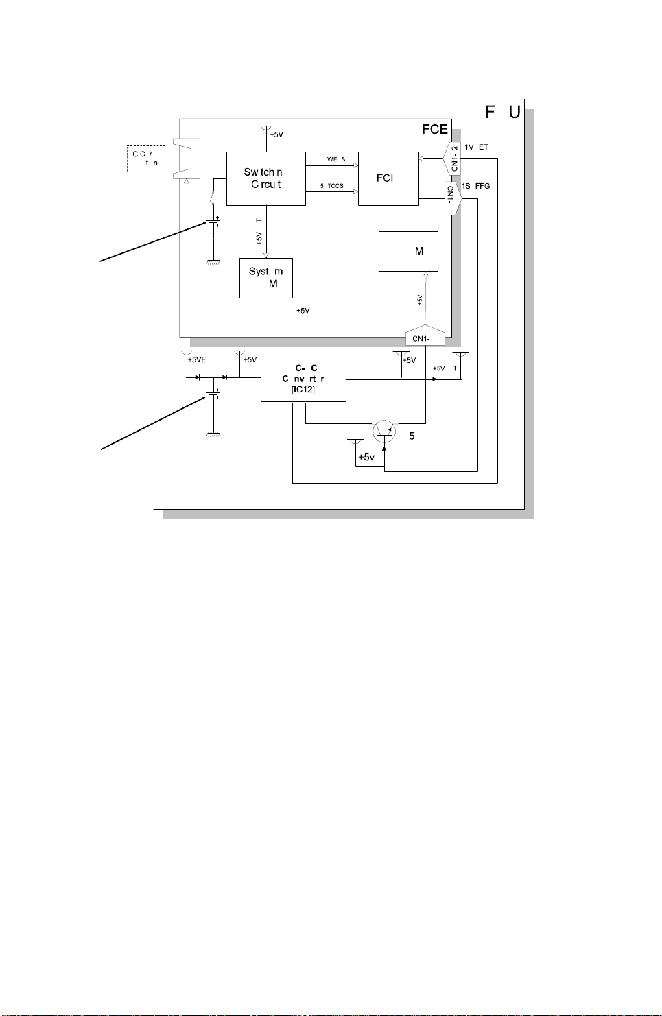
1.6.2. Memory Back-up Circuit
[A]
[B]
H516V512.wmf
The +5VBAT supply from the lithium bat te ry [ A] backs up the syst em RAM
which contains system para met ers an d pro gra mmed telephone numbers,
and the real time clock in the main cpu. The 5RTCCS signal tells the main
cpu whether the back-up powe r (+5VBAT) is coming from the battery or from
the +5V power supply.
A rechargeable lithium batt ery [B] and the dc/dc converter on the FDU back
up the DRAM (SAF memory) for one hour, if there is data in the SAF memory
and the power is switched off. While the main power is on, the +5 VE supply
recharges the battery. The battery recharges in o ne or t wo d ays.
The battery [B] generates ab ou t 3 volt s (max. 3. 2 vo lts). The dc/dc converter
(IC12) lifts this voltage to 5 volt s so it can be used as the +5 VD sup ply fo r
SAF backup. The CPU monit ors th e voltage of the +5VD sup ply wit h t he
1VDET signal. Whe n th e ba tt ery ha s run do wn, and the volta ge is lower tha n
4.4 volts, the CPU stops the dc/dc converter by dropping 1SAFFG to low and
the machine stops backing up th e memory.
There is no battery switch for the battery [B].
1-21
H516D503.wmf
May 29th, 1995 DETAILED SECTION DESCRIPTIONS
SCANNER
2. DETAILED SECTION DESCRIPTIONS
2.1. SCANNER
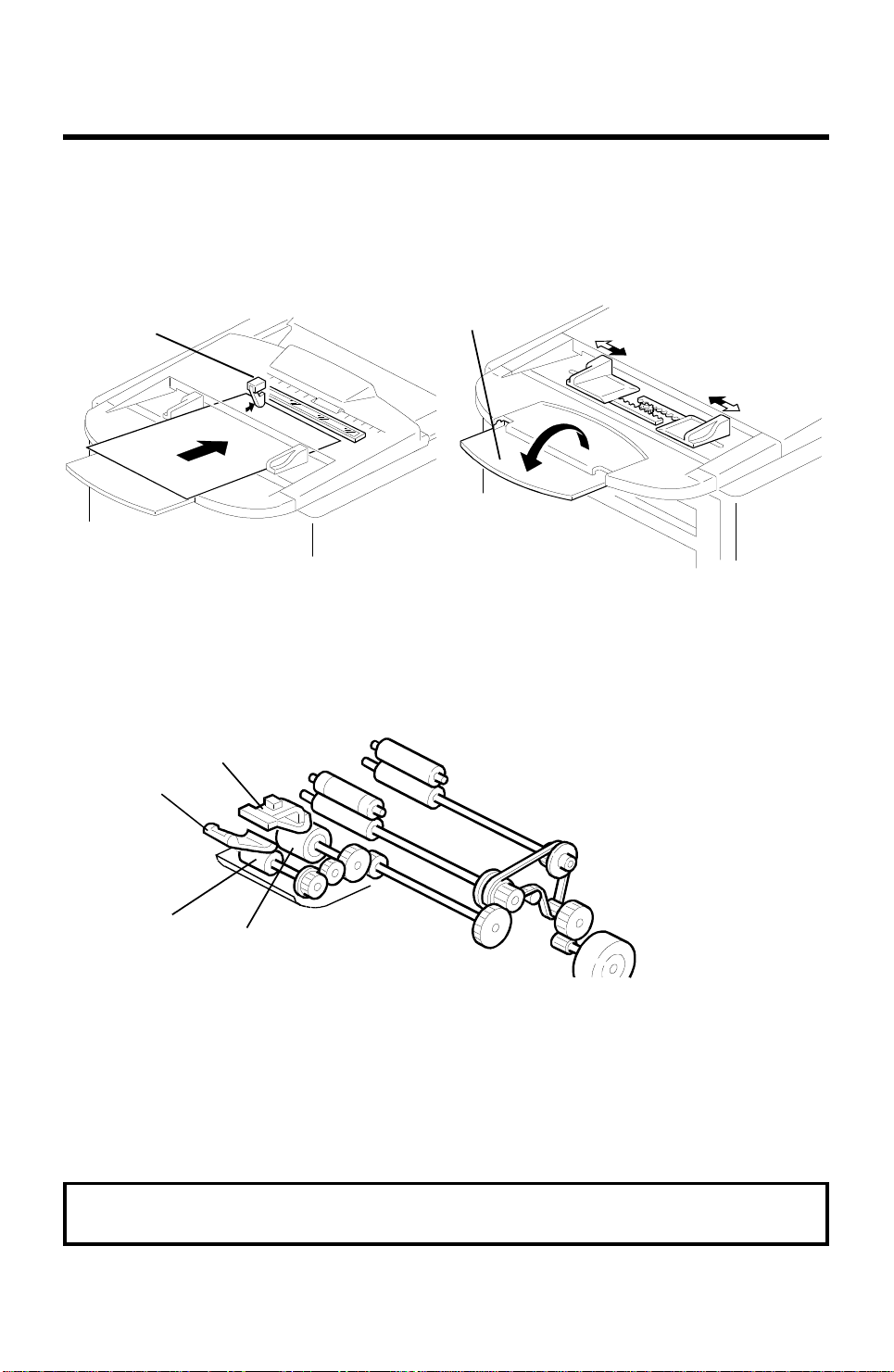
2.1.1. Mechanisms
1. Document Detection
[A]
[B]
H516D501.wmf
H516D500.wmf
The document se nso r [A] detects when a do cument is placed in the ADF. The
fold-down extension [B] help s to sup port longer documents.
2. Pick-up and Separation
[D]
[A]
[B]
[C]
Plate [A] aligns th e leading edges of the pa ge s of the document. When the
machine starts feeding the docu men t, the mecha nical clutch mechanism in
the ADF roller unit lifts up the pick-up roller [B ] t o f eed the bott om sheet of the
document. Then, the feed roller [C] feeds the sheet into the sca nner.
The separation rubbe r plate [D] prevents the feed roller from fe ed ing mo re
than one sheet at a time.
Cross reference
ADF mechanical clutch mechanism: Group 3 Facsimile Manual, page 2-2-8
2-1

[D]
[E]
DETAILED SECTION DESCRIPTIONS May 29th, 1995
SCANNER
3. Drive Mechanism
[C]
[B]
[A]
H516D502.wmf
The tx motor [A] drives the pick-up roller [B], feed roller [C], R1 roller [D], an d
R2 roller [E].
The scanning speed fo r each resolution mode is as follows.
Resolution Scan speed (/A4)
Standard - Storage to SAF (Memory Tx or Multi-copy mode)
Standard - Immediate Tx or Single copy mode
Detail
Fine
2.83 s
5.65 s
5.65 s
11.30 s
The scanner can feed pap er up to 304 mm (1 2. 0" ) wid e, howe ver the actual
scan width is 216 mm (8.5").
The maximum acceptable document page length can be adju ste d to 0.6 m
(23.6"), 1.2 m (47.2"), or 14 m (46 ft). The default setting is 1.2 m.
Cross reference
Maximum document length: Scanner Switch 00, bits 2 and 3.
2-2

[C]
[G]
[D]
May 29th, 1995 DETAILED SECTION DESCRIPTIONS
SCANNER
4. Image Scanning
[A]
[B]
[F]
[E]
H516D544.wmf
The scanner consists of a sha din g plate [A] and a contact ima ge senso r
(CIS) assembly [B]. Insid e the CIS are an exposure glass [C], a rod lens array [D], an image sensor [E], and an LED array [F] .
The image sensor consists of a row of 1728 photo sen sitive elements (Letter
width x 8 dots/mm). Light from the LED array is reflected fro m the docu men t
and focused onto the image sensor by the rod lens array. Because of the
short optical path inside the CIS, the focal depth is much shorter than for a
CCD type scanner. Because of this, the spring [G] pushes the shading plate
[A] so that the docume nt surface always touches the expo sure glass at the
scan line.
The image sensor assembly is adju sted at the factory, so it does not need
any adjustment at replacement in the field.
The image sensor scans the origin al on e line at a time , an d ou tputs an analog signal for each line. The voltage from each element depends on the
intensity of the light reflect ed from th e orig ina l ont o the ele ment; the intensity
of the light depends on th e da rkness of the area of the docu men t it was reflected from.
2-3

[A]
DETAILED SECTION DESCRIPTIONS May 29th, 1995
SCANNER
5. Sub Scan Resolution Conversion
Standard: The machine fe eds t he docu men t in 7.7 line/mm steps, an d sca ns
it in accordance with the set ting of scanner bit switch 00, bit 4. A scanning
resolution of 3.85 lines/mm means that the machin e scans once every two
motor steps.
Scanner bit switch 00
Bit 4 = 0 Bit 4 = 1
Scan - 7.7 l/mm
Tx/Copy - 3.85 l/mm
(OR processed)
OR processing is always
disabled.
Immediate tx/ Copying
Scanning to memory
Scan - 3.85 l/mm
Tx/Copy - 3.85 l/mm
Scan - 3.85 l/mm
Tx/Copy - 3.85 l/mm
Detail: The machin e fe ed s and scans the document in 7.7 line/ mm st eps.
The scanned lines are tra nsmit ted without any conversion.
Fine: The machine feeds and scans the document in 15.4 lin e/ mm st eps.
The scanned lines are transmit te d without any conversion. In memory tra nsmission, if the other terminal cannot receive a message at Fine resolution,
alternate lines (even-numbered lines) are deleted before transmission.
6. Stamping
FDU
FCE
FCIP EXIO
+24VD
CN18-6
24
CN18-5
Stamp
H516D542.wmf
The original always stops at the stamping position after the page was transmitted (immediate transmission) or stored (memory transmission)
successfully.
If the Stamp LED is turn ed on, the cp u dro ps the voltage at CN18-5 for 50 0
ms to activate the stampe r sole no id [A]. Then the original is fed o ut of the
scanner.
If the Stamp LED is turn ed off, the machine fee ds ou t th e original without
stamping.
2-4
May 29th, 1995 DETAILED SECTION DESCRIPTIONS
SCANNER
2.1.2. Scanner Timing Chart
1. Timing Chart
H516D543.wmf
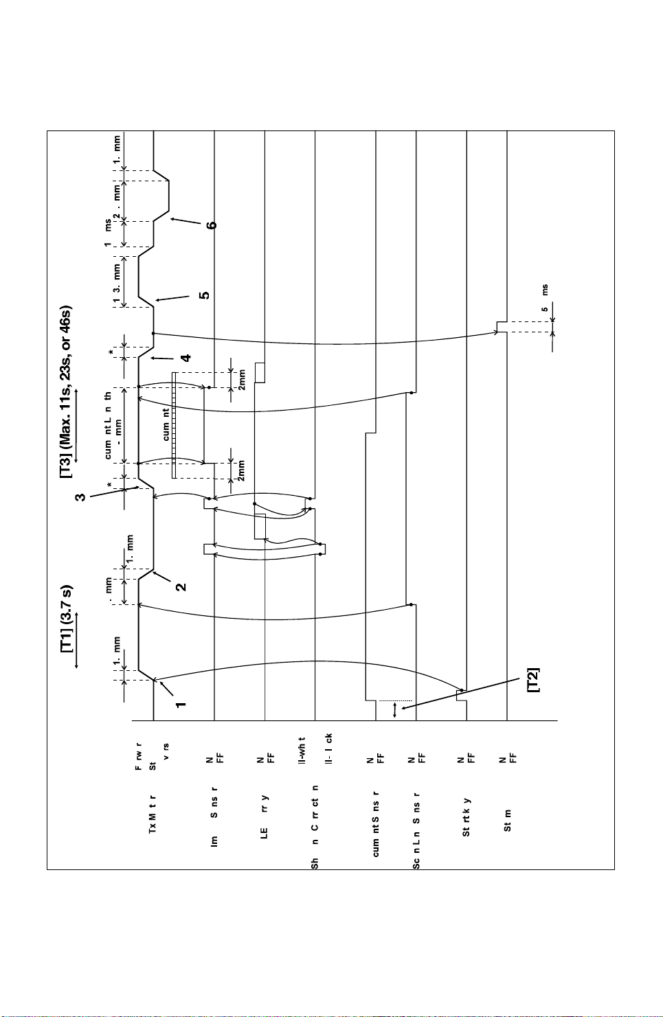
The following describes what is happening at points 1 to 6 on the timing chart .
2-5

DETAILED SECTION DESCRIPTIONS May 29th, 1995
SCANNER
1. When the Start key is pressed, the tx moto r f ee ds th e original to the scan
line sensor.
2. The tx motor stops for aut o sh ad ing to take place.
3. After auto shading, the tx motor feeds the origina l through the scanner.
4. The tx motor stops when th e original is at the stamping p osition.
5. The tx motor feeds the original out of the scanner.
6. The tx motor reverses so that the pick-up roller un it ret urn s to its home position.
2. Jam Conditions
The main cpu detects a docume nt jam if one of the following con ditions occurs.
Jam Condition Description Error
Code
Non-feed
Incorrect sensor
conditions
Maximum document
length exceeded
Error during feed-out
Cover open
The scan line sensor does not switch on within
3.7 s [T1] of the tx motor starting.
The scan line sensor switches on while the
document sensor is off [T2].
The scan line sensor does not turn off after the
maximum document length has been fed since it
turned on [T3]. This is after 11 s at standard
resolution for memory tx, 23 s at standard
resolution for immediate tx or at detail resolution,
or 46 s at fine resolution (all these times are for a
1.2 m long document).
When the final page of the document has been
fed out of the scanner, or when a jammed
document has been removed, the tx motor
reverses. This error occurs if a document is placed
into the feeder while the motor is rotating.
The ADF cover and/or printer cover are open while
the machine is working.
1-00
1-01
No error
code
No error
code
2-6
May 29th, 1995 DETAILED SECTION DESCRIPTIONS
SCANNER
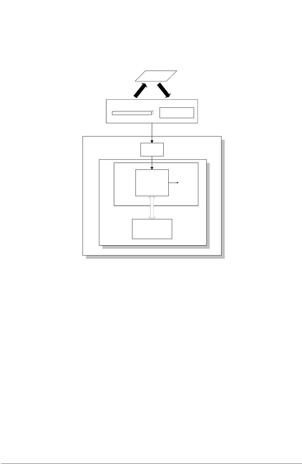
2.1.3. Video Processing
1. Analog Signal Processing
Original
Contact Image SensorAsse mbly
Image
LED Array
Amplifier
Sensor
Analog data
DIP
FCIP
Video SRAM
(VRAM)
FCE
FDU
Binary
data
H516D545.wmf
The analog video signal fro m the cont act image sensor assembly is amplified
on the FDU, then transferred to th e DIP (Digital Image Processor) inside the
FCIP.
2-7
 Loading...